RU2566183C2 - Plough with device for lifting of at least one plough beam - Google Patents
Plough with device for lifting of at least one plough beam Download PDFInfo
- Publication number
- RU2566183C2 RU2566183C2 RU2011136840/13A RU2011136840A RU2566183C2 RU 2566183 C2 RU2566183 C2 RU 2566183C2 RU 2011136840/13 A RU2011136840/13 A RU 2011136840/13A RU 2011136840 A RU2011136840 A RU 2011136840A RU 2566183 C2 RU2566183 C2 RU 2566183C2
- Authority
- RU
- Russia
- Prior art keywords
- plow
- crankcase
- hook
- plow according
- ridge
- Prior art date
Links
Images

Classifications
-
- A—HUMAN NECESSITIES
- A01—AGRICULTURE; FORESTRY; ANIMAL HUSBANDRY; HUNTING; TRAPPING; FISHING
- A01B—SOIL WORKING IN AGRICULTURE OR FORESTRY; PARTS, DETAILS, OR ACCESSORIES OF AGRICULTURAL MACHINES OR IMPLEMENTS, IN GENERAL
- A01B3/00—Ploughs with fixed plough-shares
- A01B3/36—Ploughs mounted on tractors
- A01B3/40—Alternating ploughs
- A01B3/42—Turn-wrest ploughs
-
- A—HUMAN NECESSITIES
- A01—AGRICULTURE; FORESTRY; ANIMAL HUSBANDRY; HUNTING; TRAPPING; FISHING
- A01B—SOIL WORKING IN AGRICULTURE OR FORESTRY; PARTS, DETAILS, OR ACCESSORIES OF AGRICULTURAL MACHINES OR IMPLEMENTS, IN GENERAL
- A01B61/00—Devices for, or parts of, agricultural machines or implements for preventing overstrain
- A01B61/04—Devices for, or parts of, agricultural machines or implements for preventing overstrain of the connection between tools and carrier beam or frame
- A01B61/044—Devices for, or parts of, agricultural machines or implements for preventing overstrain of the connection between tools and carrier beam or frame the connection enabling a yielding pivoting movement around a substantially horizontal and transverse axis
- A01B61/046—Devices for, or parts of, agricultural machines or implements for preventing overstrain of the connection between tools and carrier beam or frame the connection enabling a yielding pivoting movement around a substantially horizontal and transverse axis the device including an energy accumulator for restoring the tool to its working position
- A01B61/048—Devices for, or parts of, agricultural machines or implements for preventing overstrain of the connection between tools and carrier beam or frame the connection enabling a yielding pivoting movement around a substantially horizontal and transverse axis the device including an energy accumulator for restoring the tool to its working position the connection or the energy accumulator being active in two opposite directions, e.g. for reversible plows
-
- A—HUMAN NECESSITIES
- A01—AGRICULTURE; FORESTRY; ANIMAL HUSBANDRY; HUNTING; TRAPPING; FISHING
- A01B—SOIL WORKING IN AGRICULTURE OR FORESTRY; PARTS, DETAILS, OR ACCESSORIES OF AGRICULTURAL MACHINES OR IMPLEMENTS, IN GENERAL
- A01B63/00—Lifting or adjusting devices or arrangements for agricultural machines or implements
- A01B63/002—Devices for adjusting or regulating the position of tools or wheels
- A01B63/008—Vertical adjustment of tools
Landscapes
- Life Sciences & Earth Sciences (AREA)
- Engineering & Computer Science (AREA)
- Mechanical Engineering (AREA)
- Soil Sciences (AREA)
- Environmental Sciences (AREA)
- Soil Working Implements (AREA)
- Lifting Devices For Agricultural Implements (AREA)
Abstract
Description
Изобретение относится к общей области сельскохозяйственной механизации и, в частности, к области плугов. Изобретение относится к плугу, содержащему раму, на которой установлен, по меньшей мере, один грядиль при помощи соответствующего картера, при этом грядиль содержит на своем переднем конце поворотную ось, опирающуюся на опору, выполненную в указанном картере, при этом удержание указанного грядиля на указанном картере обеспечивают при помощи тяги, на которую действует тяговым усилием силовой цилиндр.The invention relates to the general field of agricultural mechanization and, in particular, to the field of plows. The invention relates to a plow containing a frame on which at least one bed is mounted using an appropriate crankcase, and the bed contains at its front end a pivot axis resting on a support made in the specified crankcase, while holding the specified bed on the specified the crankcase is provided with traction, which is acted upon by the traction force of the power cylinder.
В настоящее время размер плуга определяют с учетом мощности и подъемной силы трактора, а также с учетом состояния почвы различных разрабатываемых делянок. Разрабатываемые делянки различаются по своей форме, рельефу и типам почвы. Подъемная сила трактора определяет максимальный вес и, следовательно, максимальное число плужных корпусов. Мощность трактора позволяет определить возможное число плужных корпусов в данных рабочих условиях. Один плужный корпус потребляет от 20 до 40 лошадиных сил в зависимости от глубины вспашки и от связности почвы. Таким образом, мощность, поглощаемая плужным корпусом, меняется в зависимости от обрабатываемых делянок. Выбор числа плужных корпусов ограничен для глинистых почв, называемых тяжелыми, которые требуют повышенной тяговой мощности от 40 до 45 лошадиных сил на один плужный корпус. Таким образом, делянки с тяжелыми почвами существенно снижают производительность плуга на сельскохозяйственной ферме, делянки которой по большей части состоят из легких почв.Currently, the size of the plow is determined taking into account the power and lifting force of the tractor, as well as taking into account the soil condition of the various developed plots. The developed plots vary in their shape, topography and soil types. The lifting force of the tractor determines the maximum weight and, therefore, the maximum number of plow bodies. The power of the tractor allows you to determine the possible number of plow bodies in these operating conditions. One plow body consumes from 20 to 40 horsepower depending on the depth of plowing and on the connectivity of the soil. Thus, the power absorbed by the plow body varies depending on the plots being farmed. The choice of the number of plow bodies is limited for clay soils called heavy, which require increased traction power from 40 to 45 horsepower per plow body. Thus, plots with heavy soils significantly reduce the productivity of the plow on an agricultural farm, the plots of which for the most part consist of light soils.
Известна возможность адаптации числа плужных корпусов, применяемых в условиях работы с полунавесным плугом. Такой плуг содержит плужные корпусы, распределенные между передней частью и задней частью. Между передней и задней частями находится тележка с колесами. При таких плугах большой длины можно полностью поднимать плужные корпусы задней части на трудных делянках и/или в конце поля. Так, например, на наклонных участках земли работают только передние плужные корпусы, а вся задняя часть при этом поднята. Как правило, в задней части плуга установлены три и даже четыре плужных корпуса. Следовательно, поднимают все эти три и даже четыре корпуса, которые не участвуют в работе. Следовательно, адаптация числа плужных корпусов к условиям и к почве является приблизительной и никак не оптимальной.A known possibility of adapting the number of plow bodies used in conditions of work with a semi-mounted plow. Such a plow contains plow bodies distributed between the front and rear. Between the front and rear parts is a cart with wheels. With such long plows, the plow bodies of the rear part can be fully raised on difficult plots and / or at the end of the field. So, for example, on inclined land only the front plow bodies work, and the entire rear part is raised. As a rule, three or even four plow bodies are installed at the rear of the plow. Consequently, they raise all three or even four buildings that are not involved in the work. Therefore, the adaptation of the number of plow bodies to conditions and to the soil is approximate and in no way optimal.
Известны также плуги с гидравлическими безостановочными предохранительными устройствами, позволяющими откинуть грядиль на короткое время, чтобы освободить плужный корпус, встречающий на своем пути препятствие. Машина такого типа содержит грядили, установленные на раме через соответствующий картер. Передний конец грядиля содержит поворотную ось, которая опирается на опору, выполненную в указанном картере. Удержание указанного грядиля на указанном картере обеспечивают при помощи тяги, на которую тяговым усилием действует силовой цилиндр. Силовой цилиндр является частью масляно-пневматического механизма, образующего гидравлическое безостановочное предохранительное устройство. Этот механизм позволяет плужному корпусу, встречающему препятствие, откинуться назад и автоматически вернуться в положение на почве после прохождения препятствия. Для этого масляно-пневматический механизм содержит также амортизирующий элемент, представляющий собой аккумулятор с резервуаром сжатого азота. Аккумулятор позволяет возвращать грядиль и плужный корпус в рабочее положение. Благодаря аккумулятору, грядиль включается в работу сразу после прохождения препятствия без участия тракториста и без остановки трактора. Таким образом, грядиль поднимается только, когда плужный корпус встречает препятствие во время вспашки. Гидравлическое безостановочное предохранительное устройство не позволяет удерживать плужный корпус над землей в отсутствие препятствия.Plows with hydraulic non-stop safety devices are also known that allow the beds to be folded out for a short time to release the plow body that encounters an obstacle in its path. A machine of this type contains ridges mounted on a frame through an appropriate crankcase. The front end of the ridge contains a rotary axis, which rests on a support made in the specified crankcase. The retention of the specified ridge on the specified crankcase is provided by means of a traction, on which the power cylinder acts by traction. The master cylinder is part of an oil-pneumatic mechanism forming a hydraulic non-stop safety device. This mechanism allows the plow body that meets the obstacle to lean back and automatically return to the ground position after passing the obstacle. For this, the oil-pneumatic mechanism also contains a shock-absorbing element, which is a battery with a reservoir of compressed nitrogen. The battery allows you to return the beds and plow body in working position. Thanks to the battery, the beds come into operation immediately after passing the obstacle without the participation of the tractor driver and without stopping the tractor. Thus, the ridges rise only when the plow body meets an obstacle during plowing. The hydraulic non-stop safety device does not allow holding the plow body above the ground in the absence of an obstacle.
Задачей настоящего изобретения является устранение вышеуказанных недостатков. В частности, задачей изобретения является создание плуга, в котором число работающих плужных корпусов можно преднамеренно адаптировать в зависимости от обрабатываемой делянки и в зависимости от типа трактора.The objective of the present invention is to remedy the above disadvantages. In particular, an object of the invention is to provide a plow in which the number of working plow bodies can be deliberately adapted depending on the plot being cultivated and depending on the type of tractor.
В связи с этим, важный отличительный признак изобретения состоит в том, что указанный плуг содержит устройство, позволяющее преднамеренно поднимать грядиль, поворачивая его вокруг оси, которая по существу соответствует поворотной оси. Благодаря этому устройству можно управлять положением соответствующего грядиля и преднамеренно уменьшать или увеличивать число работающих плужных корпусов. Таким образом, число плужных корпусов будет меняться в зависимости от характера почвы, чтобы общая мощность, потребляемая работающими плужными корпусами, предельно приближалась к максимальной мощности трактора.In this regard, an important distinguishing feature of the invention is that the plow contains a device that allows you to deliberately raise the beds, turning it around an axis, which essentially corresponds to the rotary axis. Thanks to this device, it is possible to control the position of the corresponding ridge and to deliberately reduce or increase the number of working plow bodies. Thus, the number of plow hulls will vary depending on the nature of the soil, so that the total power consumed by the working plow hulls is as close as possible to the maximum tractor power.
Согласно другому отличительному признаку, все грядили снабжены устройством в соответствии с настоящим изобретением. Таким образом, облегчается вход и выход из борозды, за счет чего сокращаются не обработанные зоны. Каждый грядиль управляется индивидуально и может входить и выходить из почвы вдоль одной линии.According to another distinguishing feature, all beds are equipped with a device in accordance with the present invention. Thus, entry and exit from the furrow is facilitated, due to which untreated zones are reduced. Each ridge is individually controlled and can enter and exit the soil along one line.
Другие отличительные признаки и преимущества изобретения будут более очевидны из нижеследующего описания, представленного в качестве неограничивающего примера выполнения, со ссылками на прилагаемые чертежи.Other features and advantages of the invention will be more apparent from the following description, presented as a non-limiting example of implementation, with reference to the accompanying drawings.
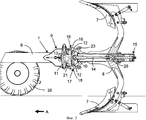
На фиг. 1 показан плуг в соответствии с настоящим изобретением в рабочем положении, последний плужный корпус которого удерживается над землей, вид сбоку;In FIG. 1 shows a plow in accordance with the present invention in a working position, the last plow body of which is held above the ground, side view;
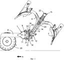
на фиг. 2 показан грядиль плуга во время работы, вид сбоку;in FIG. 2 shows the plow beds during operation, side view;
на фиг. 3 показан грядиль плуга в поднятом положении, вид сбоку;in FIG. 3 shows the plow beds in a raised position, side view;
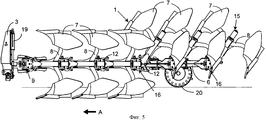
на фиг. 4 показан вход в борозду при работе с плугом в соответствии с настоящим изобретением, вид сверху;in FIG. 4 shows the entrance to the furrow when working with a plow in accordance with the present invention, top view;
на фиг. 5 показан плуг, изображенный на фиг. 4, вид сбоку.in FIG. 5 shows the plow of FIG. 4, side view.
Показанное на фиг. 1 сельскохозяйственное орудие является плугом 1. Плуг 1 предназначен для соединения с трактором 2 при помощи сцепного узла 3. В частности, плуг 1 соединяют со сцепным устройством 4 трактора 2. На фиг. 1 показаны только задняя часть трактора 2 и его задние колеса 5. Трактор 2 тянет плуг 1 в направлении движения, показанном стрелкой А. В дальнейшем тексте описания понятия «передний», «задний» и «спереди», «сзади» следует рассматривать по отношению к направлению движения А. Плуг 1 содержит также раму 6, плужные корпусы 7, детали соединения между рамой 6 и плужными корпусами 7, предохранительные устройства, которые при столкновении с препятствием позволяют избежать поломки основной детали плуга 1, и устройства регулирования. Как правило, на раме установлено несколько плужных корпусов 7, которые являются рабочими инструментами, разрезающими, поднимающими и переворачивающими полосу земли. Каждый плужный корпус 7 жестко соединен с рамой 6 плуга 1 через соответствующие грядиль 8 и картер 9. Плуг 1, показанный на фиг. 1, является навесным плугом и соединен с трактором 2 при помощи трехточечного сцепного устройства, управляемого посредством гидравлического подъемного средства трактора. Плуг является оборотным и оборудован шестью плужными корпусами 7.Shown in FIG. 1, the agricultural implement is a
На фиг. 2 более детально показан грядиль 8, установленный на раме 6 через соответствующий картер 9. Грядиль соединен с рамой 6 при помощи горизонтального шарнира 10 по существу с горизонтальной осью, перпендикулярной к рабочему направлению. Картер 9 соединен с рамой 6 при помощи вертикального шарнира 11 с осью, по существу вертикальной относительно рабочего направления. На своем переднем конце грядиль 8 содержит поворотную ось 12, опирающуюся на опору 13, выполненную в указанном картере 9. Поворотная ось 12 по существу параллельна оси горизонтального шарнира 10. Тяга 14 удерживает грядиль 8 прижатым к опоре 13 картера 9. На тягу 14 тяговым усилием действует силовой цилиндр 15, что позволяет плужному корпусу 7 оставаться в земле. Каждый грядиль 8 оборудован гидравлическим безостановочным предохранительным устройством, которое позволяет ему повернуться вверх, когда плужный корпус 7 натыкается на препятствие, образованное камнем. Один конец тяги 14 соединен с горизонтальным шарниром 10, а другой конец соединен с силовым цилиндром 15 через другой шарнир 25. Силовой цилиндр 15 тянет за тягу 14, чтобы удерживать грядиль 8 в рабочем положении.In FIG. 2 shows in more detail the
Согласно важному отличительному признаку, плуг 1 содержит устройство 16 для преднамеренного подъема грядиля 8 путем поворота вокруг оси, по существу соответствующей указанной поворотной оси 12. Благодаря этому устройству 16, указанный грядиль 8 можно преднамеренно или умышленно откидывать, не меняя положения рамы 6 плуга 1. Таким образом, число работающих плужных корпусов плуга можно преднамеренно уменьшить для адаптации к условиям почвы. В дополнение к отключению в случае перегрузки или столкновения с препятствием во время вспашки пользователь может уменьшить число плужных корпусов путем подъема соответствующего грядиля.According to an important distinguishing feature, the
В примере осуществления, представленном на фиг. 1, последний грядиль 8 оборудован устройством 16, позволяющим поднимать его и удерживать над землей. Он убирается, то есть поворачивается в направлении против часовой стрелки относительно рамы 6. Таким образом, плуг 1 работает только с пятью плужными корпусами, тогда как на нем их установлено шесть. Последний грядиль 8 с установленным или установленными на нем плужными корпусами 7 можно удерживать над землей для работы в трудных условиях. Благодаря изобретению, число плужных корпусов можно менять в зависимости от условий почвы, чтобы поглощаемая работающим плужным корпусом мощность могла совпадать или максимально приближаться к максимальной мощности, развиваемой трактором. На фиг. 2 показаны последний грядиль 8 в его рабочем положении и тяга 14, по существу находящаяся на одной прямой с рамой 6 плуга 1.In the embodiment shown in FIG. 1, the
На фиг. 3 показан последний грядиль 8 в повернутом положении, при этом плужные корпусы 7 подняты над землей. При этом можно отметить, что тяга 14 грядиля 8 повернулась относительно рамы 6 плуга 1. Рама 6 остается по существу параллельно поверхности земли. Таким образом, конструкция плуга 1 не переместилась, а повернулся только грядиль 8, оборудованный устройством 16. Подъем грядиля 8 происходит за счет толкающего усилия указанной тяги 14 на указанный картер 9. Это толкающее усилие позволяет повернуть грядиль 8 вверх вокруг поворотной оси 12. Для этого устройство 16 подъема грядиля 8 содержит двухступенчатый силовой цилиндр. Предпочтительно силовой цилиндр 15, соединенный с тягой 14, выполнен в виде двухступенчатого силового цилиндра. Таким образом, именно двухступенчатый силовой цилиндр 15 толкает тягу 14, чтобы повернуть грядиль 8 в положение над землей. В большую камеру силового цилиндра 15 подают масло, чтобы поднять грядиль 8 путем его поворота и удерживать его над землей. Предпочтительно устройством 16 для подъема грядиля 8, в частности двухступенчатым силовым цилиндром 15, управляют из кабины трактора 2.In FIG. 3 shows the
Согласно другому важному отличительному признаку, указанное устройство 16 содержит также систему 17 удержания поворотной оси 12 на опоре 13 картера 9. За счет этого обеспечивают направление поворота грядиля 8, так как поворотная ось 12 не может отойти от опоры 13 картера 9. Для этого система 17 удержания содержит крюк 18. Крюк 18 проходит по существу над поворотной осью 12 и выполнен с возможностью взаимодействия с частью периферии поворотной оси 12. Крюк 18 взаимодействует с верхней частью поворотной оси 12. Крюк 18 выполнен также с возможностью обеспечения бокового смещения примерно на 6° в случае, когда плужный корпус 7 сталкивается с камнем своей боковой стороной. Предпочтительно система 17 удержания связана с картером 9. Таким образом, поворот грядиля 8 происходит вокруг оси, по существу соответствующей поворотной оси 12.According to another important distinguishing feature, said
Показанный на фигурах плуг 1 является оборотным, и на каждом грядиле 8 установлен правый плужный корпус и левый плужный корпус. Плужные корпусы симметричны относительно горизонтальной плоскости, проходящей через горизонтальный шарнир 10. Рама 6 поворачивается на 180°, чтобы плужные корпусы работали поочередно, и содержит поворотное устройство 19. Плуг 1 содержит также бороздное колесо 20. Это колесо 20 установлено на заднем конце рамы 6 и обеспечивает контроль глубины вспашки в дополнение к сцепному устройству 4 трактора 2.The
Как показано на фиг. 2, передний конец грядиля 8 содержит две поворотные оси 12, верхнюю поворотную ось и нижнюю поворотную ось. Каждая из них опирается на соответствующую опору 13, выполненную в картере 9. Верхняя поворотная ось находится над нижней поворотной осью, и они симметричны относительно горизонтальной плоскости, проходящей через горизонтальный шарнир 10. В показанном рабочем положении силовой цилиндр 15 действует тяговым усилием на тягу 14, чтобы обе поворотные оси оставались прижатыми к опорам 13 картера 9. Поворотные оси 12 находятся спереди относительно оси горизонтального шарнира 10. Силовой цилиндр 15 выполняет также функцию гидравлического безостановочного предохранительного устройства, то есть грядиль 8 может высвободиться и моментально выйти из земли, когда плужный корпус 7 наталкивается на препятствие, затем опять заходит в землю сразу после прохождения препятствия. Диапазон предохранительного срабатывания на грядиле 8 можно регулировать. На фиг. 3 и 4 опоры 13 показаны пунктирными линиями. Эти опоры 13 являются полуцилиндрическими и выполнены в картере 9. Согласно не показанному альтернативному варианту, на грядиле выполняют цилиндрические опоры 13, а на картере 9 выполняют поворотные оси 12. В альтернативном варианте опоры 13 могут быть сферическими. Показанная тяга 14 проходит в грядиле 8, и имеется в виду центральная тяга. Согласно альтернативному варианту, тяга находится снаружи грядиля.As shown in FIG. 2, the front end of the
Таким образом, система 17 удержания содержит два крюка 18. Оба крюка 18 соединены цилиндрической осью 21. Они установлены на картере 9. Система 17 удержания содержит верхний крюк и нижний крюк. Указанный нижний крюк находится снизу и по существу на вертикали с указанным верхним крюком. Движение указанного нижнего крюка связано с движением указанного верхнего крюка через цилиндрическую ось 21. Цилиндрическая ось 21 и крюки 18 перемещаются в картере 9.Thus, the
Система 17 удержания выполнена так, что когда задействован верхний крюк, нижний крюк являлся неактивным, и наоборот. Таким образом, она адаптирована для оборотного плуга, плужные корпусы которого работают поочередно. Активация системы 17 удержания происходит автоматически в зависимости от находящихся в работе плужных корпусов. Соответствующий крюк 18 встает на место за счет силы тяжести. Согласно не показанному альтернативному варианту, активация системы 17 удержания и, в частности, соответствующего крюка 18 является механизированной. В примере, показанном на фиг. 2, верхний крюк является активным во время правой вспашки. Во время левой вспашки активным является нижний крюк. Расстояние, разделяющее верхний крюк и нижний крюк, является постоянным и превышает промежуток между верхней поворотной осью и нижней поворотной осью грядиля 8. Задняя часть крюка 18 не входит в контакт ни с одной деталью, что позволяет грядилю 8 перемещаться в боковом направлении в случае контакта с камнем боковой стороны плужного корпуса 8. С верхним крюком, удерживающим верхнюю поворотную ось прижатой к верхней опоре, поворотное движение грядиля 8 вокруг верхней поворотной оси направляется как во время подъема, так и во время опускания. Кроме того, поскольку нижний крюк не задействован, грядиль 8 может поворачиваться только вокруг верхней поворотной оси, когда силовой цилиндр 15 действует толкающим усилием.The
На фиг. 3 показан последний грядиль 8 плуга 9 в поднятом положении. Для этого в большую камеру 22 силового цилиндра 15 двойного действия поступает масло, и силовой цилиндр 15 удлиняется, поворачивая грядиль 8 вокруг верхней поворотной оси. На фигурах трубопроводы питания маслом силовых цилиндров 15 не показаны. Поскольку верхний крюк является активным и зацепляется с верхней поворотной осью, нижняя поворотная ось отходит от нижней опоры картера 9, обеспечивая поворот. После полного выхода штока силового цилиндра 15 плужные корпусы 7 находятся на землей и, следовательно, не переворачивают почву. Чтобы крюк 18 оставался активным в поднятом положении грядиля 8, последний опирается на поворотную ось 12 под действием предохранительного устройства 23. Предохранительное устройство 23 находится на грядиле 8 и выполнено в виде регулируемого винта, опирающегося на верхнюю часть крюка 18.In FIG. 3 shows the
На фиг. 1, показан плуг 1 с поднятым последним грядилем 8. Плужные корпусы 7 этого грядиля 8 остаются над поверхностью земли. Можно также оборудовать два и даже три последних грядиля 8 плуга 1 устройством 16 подъема грядиля. Это позволяет использовать на короткое время шестикорпусной плуг в очень сложных условиях, уменьшая число работающих плужных корпусов только до четырех или трех плужных корпусов.In FIG. 1, a
В примере осуществления, показанном на фиг. 4 и 5, все грядили 8 плуга 1 оборудованы устройством 16 для подъема грядиля 8. Таким образом, каждый грядиль 8 можно поднимать по выбору, что позволяет укорачивать поворотные полосы во время разворотов в конце делянки. Поворотные полосы являются полосами длиной от 5 до 10 метров, где трактор поворачивает в конце делянки. После вспашки делянки эти поворотные полосы должны быть запаханы бороздами, перпендикулярными к главным бороздам. Как правило, эти поворотные полосы содержат чередование вспаханных треугольных зон и не вспаханных треугольных зон. При использовании плута 1 в соответствии с настоящим изобретением входом в борозду и выходом из борозды каждого грядиля 8 управляют индивидуально, чтобы свести к минимуму ширину поворотных полос. На фиг. 4 плуг 1 показан в положении входа в борозду с тремя работающими плужными корпусами и тремя плужными корпусами, которые еще остаются поднятыми. Вход и выход из борозды происходит по прямой линии 24, так как все плужные корпуса входят в борозду и выходят из борозды один за другим, как только они подходят к одной и той же линии, перпендикулярной к направлению движения. Борозды плужных корпусов 7 схематично показаны линиями, которые начинаются от прямой линии 24. С правой поворотной полосой (без треугольника) число проходов для поперечной запашки уменьшается, и запашка конца поля упрощается. На фиг. 5 показан вид сбоку плуга 1, показанного на фиг. 4. Вход в землю трех последних плужных корпусов происходит по мере приведения в действие двухступенчатого силового цилиндра 15 каждого грядиля 8. Таким образом, вход и выход в борозды укорачивается. Следует отметить, что рама 6 остается по существу параллельной поверхности земли.In the embodiment shown in FIG. 4 and 5, all
Поскольку положение каждого грядиля 8 на раме известно, можно координировать вход и выход каждого грядиля 8 в зависимости от скорости движения трактора. При автоматическом управлении через электронные средства управление различными грядилями 8 плуга 1 не зависит от опыта или квалификации пользователя.Since the position of each
Согласно альтернативному варианту, управление положением различных грядилей происходит автоматически в зависимости от их положения и от воображаемой линии, записанной в устройстве GPS.According to an alternative embodiment, the position of the various ridges is controlled automatically depending on their position and on the imaginary line recorded in the GPS device.
Плуг в соответствии с настоящим изобретением может быть простым, то есть не оборотным плугом. В этом случае устройство 17 удержания содержит только один крюк 18, положение которого на поворотной оси 12 является фиксированным. Плуг в соответствии с настоящим изобретением может быть полунавесным или прицепным плугом.The plow in accordance with the present invention can be simple, that is, not a reversible plow. In this case, the holding
Разумеется, настоящее изобретение не ограничивается описанными выше и показанными на фигурах вариантами осуществления. В него можно вносить изменения, в частности, что касается конструкции или количества различных элементов или путем замены техническими эквивалентами, не выходя при этом за рамки объема правовой защиты, определенного нижеследующей формулой изобретения.Of course, the present invention is not limited to the embodiments described above and shown in the figures. It can be amended, in particular with regard to the design or quantity of various elements or by replacement with technical equivalents, without going beyond the scope of legal protection defined by the following claims.
Claims (11)
Applications Claiming Priority (2)
| Application Number | Priority Date | Filing Date | Title |
|---|---|---|---|
| FR1057037A FR2964292B1 (en) | 2010-09-06 | 2010-09-06 | PLUNGER WITH A DEVICE FOR LIFTING AT LEAST ONE AGE |
| FR1057037 | 2010-09-06 |
Publications (2)
| Publication Number | Publication Date |
|---|---|
| RU2011136840A RU2011136840A (en) | 2013-03-10 |
| RU2566183C2 true RU2566183C2 (en) | 2015-10-20 |
Family
ID=43829788
Family Applications (1)
| Application Number | Title | Priority Date | Filing Date |
|---|---|---|---|
| RU2011136840/13A RU2566183C2 (en) | 2010-09-06 | 2011-09-05 | Plough with device for lifting of at least one plough beam |
Country Status (8)
| Country | Link |
|---|---|
| EP (1) | EP2425696B1 (en) |
| DK (1) | DK2425696T3 (en) |
| ES (1) | ES2670295T3 (en) |
| FR (1) | FR2964292B1 (en) |
| NO (1) | NO2425696T3 (en) |
| PL (1) | PL2425696T3 (en) |
| RU (1) | RU2566183C2 (en) |
| UA (1) | UA109874C2 (en) |
Cited By (1)
| Publication number | Priority date | Publication date | Assignee | Title |
|---|---|---|---|---|
| RU2631388C1 (en) * | 2016-09-26 | 2017-09-21 | Федеральное государственное бюджетное образовательное учреждение высшего образования Горский государственный аграрный университет | Cultivator section |
Families Citing this family (3)
| Publication number | Priority date | Publication date | Assignee | Title |
|---|---|---|---|---|
| DK178793B1 (en) * | 2015-07-08 | 2017-02-20 | Agro Intelligence Aps | A plough system and a method for ploughing |
| CN105519275B (en) * | 2016-02-02 | 2017-05-24 | 河北省农林科学院棉花研究所 | Cotton field soil plough layer reconstruction and matched cultivation method |
| US10806079B2 (en) | 2018-02-26 | 2020-10-20 | Deere & Company | Automatic product harvesting method and control system |
Citations (4)
| Publication number | Priority date | Publication date | Assignee | Title |
|---|---|---|---|---|
| GB1483834A (en) * | 1975-01-17 | 1977-08-24 | Ransomes Sims & Jefferies Ltd | Multi-furrow ploughs |
| FR2445099A1 (en) * | 1978-12-29 | 1980-07-25 | Fiskars Ab Oy | LOCKING MEMBER FOR A DOUBLE BRABANT, EQUIPPED WITH A CLEARING MECHANISM |
| SU1588229A1 (en) * | 1988-09-14 | 1992-06-30 | Ezhova V G | Sun pumped laser |
| GB2259839A (en) * | 1991-09-24 | 1993-03-31 | Kverneland Klepp As | Plough body position control device |
Family Cites Families (9)
| Publication number | Priority date | Publication date | Assignee | Title |
|---|---|---|---|---|
| US3561541A (en) | 1967-09-21 | 1971-02-09 | Roger W Woelfel | Tractor and implement hydraulic control system |
| FR2173784B1 (en) | 1972-03-02 | 1976-01-16 | Thieme Gerard Fr | |
| FR2535935B1 (en) | 1982-11-17 | 1986-06-20 | Huard Ucf | IMPROVEMENTS TO HYDRAULIC SAFETY SYSTEMS FOR AUTOMATIC TRIP AND RECLOSURE PLOWS |
| SE444103B (en) | 1982-12-17 | 1986-03-24 | Sture Norelius | DEVICE FOR A PLOG INCLUDING A MULTIPLE INDIVIDUALLY HIGH AND SUBSTANTLY APPLICABLE PLOG BODIES |
| NL8402323A (en) * | 1984-07-23 | 1986-02-17 | Lely Nv C Van Der | PLOW. |
| GB9100665D0 (en) | 1991-01-11 | 1991-02-27 | Massey Ferguson Services Nv | Implement control |
| DE4117947A1 (en) * | 1991-05-31 | 1992-12-03 | Leipzig Bodenbearbeitung Veb | HYDROMECHANICAL OVERLOAD PROTECTION FOR BED AND TURNING PLOWS |
| GB9610124D0 (en) | 1996-05-15 | 1996-07-24 | Massey Ferguson Sa | Control of a semi-mounted plough |
| US20080093093A1 (en) | 2006-10-24 | 2008-04-24 | Morris Industries Ltd | Combination Hydraulic Hold-Down and Lift System for an Agricultural Implement |
-
2010
- 2010-09-06 FR FR1057037A patent/FR2964292B1/en not_active Expired - Fee Related
-
2011
- 2011-09-05 PL PL11180032T patent/PL2425696T3/en unknown
- 2011-09-05 NO NO11180032A patent/NO2425696T3/no unknown
- 2011-09-05 UA UAA201110707A patent/UA109874C2/en unknown
- 2011-09-05 RU RU2011136840/13A patent/RU2566183C2/en active
- 2011-09-05 EP EP11180032.2A patent/EP2425696B1/en active Active
- 2011-09-05 DK DK11180032.2T patent/DK2425696T3/en active
- 2011-09-05 ES ES11180032.2T patent/ES2670295T3/en active Active
Patent Citations (4)
| Publication number | Priority date | Publication date | Assignee | Title |
|---|---|---|---|---|
| GB1483834A (en) * | 1975-01-17 | 1977-08-24 | Ransomes Sims & Jefferies Ltd | Multi-furrow ploughs |
| FR2445099A1 (en) * | 1978-12-29 | 1980-07-25 | Fiskars Ab Oy | LOCKING MEMBER FOR A DOUBLE BRABANT, EQUIPPED WITH A CLEARING MECHANISM |
| SU1588229A1 (en) * | 1988-09-14 | 1992-06-30 | Ezhova V G | Sun pumped laser |
| GB2259839A (en) * | 1991-09-24 | 1993-03-31 | Kverneland Klepp As | Plough body position control device |
Cited By (1)
| Publication number | Priority date | Publication date | Assignee | Title |
|---|---|---|---|---|
| RU2631388C1 (en) * | 2016-09-26 | 2017-09-21 | Федеральное государственное бюджетное образовательное учреждение высшего образования Горский государственный аграрный университет | Cultivator section |
Also Published As
| Publication number | Publication date |
|---|---|
| DK2425696T3 (en) | 2018-07-16 |
| PL2425696T3 (en) | 2018-10-31 |
| UA109874C2 (en) | 2015-10-26 |
| FR2964292B1 (en) | 2013-09-27 |
| RU2011136840A (en) | 2013-03-10 |
| FR2964292A1 (en) | 2012-03-09 |
| NO2425696T3 (en) | 2018-09-01 |
| ES2670295T3 (en) | 2018-05-29 |
| EP2425696B1 (en) | 2018-04-04 |
| EP2425696A1 (en) | 2012-03-07 |
Similar Documents
| Publication | Publication Date | Title |
|---|---|---|
| RU2654725C2 (en) | Soil cultivation implement with device for reconsolidation | |
| RU2566183C2 (en) | Plough with device for lifting of at least one plough beam | |
| BR102017015192A2 (en) | AGRICULTURAL IMPLEMENT SYSTEM | |
| RU2671148C2 (en) | Soil cultivation implement for attachment to a towing vehicle | |
| CN204377361U (en) | Compound minimum stubble-cleaning combined soil preparing machine | |
| RU2376738C1 (en) | Device for cultivation of soil in space between rows in garden | |
| RU78394U1 (en) | HARROW DISC TRAILED | |
| CA2847369C (en) | Disc clearing machine and method for making seed tracts for the forest seeding of coniferous species | |
| CN203775629U (en) | Handheld stubble cleaning, ridge forming and suppressing combined tiller applicable to hilly land | |
| EP3294049B1 (en) | An agricultural implement for use in a field comprising pre-prepared tracks | |
| CN110089219A (en) | A kind of rotary cultivator | |
| RU2007129778A (en) | SEEDER | |
| JP3744065B2 (en) | Bottom work machine and field work machine that form a uniform soil layer in the field | |
| Santos et al. | Performance of a seeder according to the displacement velocity and furrowing mechanism for fertilizer deposition | |
| CZ308529B6 (en) | Tilling unit and method using strip-till technology | |
| RU48142U1 (en) | Soil cultivating tool | |
| ES2731783T3 (en) | A depth control belt arrangement for a floor work utensil | |
| RU2492610C1 (en) | Discovator subsoil cultivator | |
| CN203289838U (en) | Drag-type bias heavy harrow with left and right harrow depth adjustable | |
| RU2360392C1 (en) | Antierosion combine unit | |
| CN201976420U (en) | Stubble-cutting mechanism for no-tillage seeder | |
| CN208891157U (en) | A kind of agricultural ditching machine | |
| RU172996U1 (en) | Disc Tillage | |
| US20200337199A1 (en) | Agricultural implement | |
| RU16421U1 (en) | COMBINED SOIL PROCESSING UNIT |