RU2553674C2 - Brake for universal electric motor - Google Patents
Brake for universal electric motor Download PDFInfo
- Publication number
- RU2553674C2 RU2553674C2 RU2012131272/07A RU2012131272A RU2553674C2 RU 2553674 C2 RU2553674 C2 RU 2553674C2 RU 2012131272/07 A RU2012131272/07 A RU 2012131272/07A RU 2012131272 A RU2012131272 A RU 2012131272A RU 2553674 C2 RU2553674 C2 RU 2553674C2
- Authority
- RU
- Russia
- Prior art keywords
- key
- braking mode
- braking
- motor
- mode
- Prior art date
Links
Images
Classifications
-
- H—ELECTRICITY
- H02—GENERATION; CONVERSION OR DISTRIBUTION OF ELECTRIC POWER
- H02P—CONTROL OR REGULATION OF ELECTRIC MOTORS, ELECTRIC GENERATORS OR DYNAMO-ELECTRIC CONVERTERS; CONTROLLING TRANSFORMERS, REACTORS OR CHOKE COILS
- H02P3/00—Arrangements for stopping or slowing electric motors, generators, or dynamo-electric converters
- H02P3/06—Arrangements for stopping or slowing electric motors, generators, or dynamo-electric converters for stopping or slowing an individual dynamo-electric motor or dynamo-electric converter
- H02P3/18—Arrangements for stopping or slowing electric motors, generators, or dynamo-electric converters for stopping or slowing an individual dynamo-electric motor or dynamo-electric converter for stopping or slowing an ac motor
- H02P3/22—Arrangements for stopping or slowing electric motors, generators, or dynamo-electric converters for stopping or slowing an individual dynamo-electric motor or dynamo-electric converter for stopping or slowing an ac motor by short-circuit or resistive braking
-
- H—ELECTRICITY
- H02—GENERATION; CONVERSION OR DISTRIBUTION OF ELECTRIC POWER
- H02P—CONTROL OR REGULATION OF ELECTRIC MOTORS, ELECTRIC GENERATORS OR DYNAMO-ELECTRIC CONVERTERS; CONTROLLING TRANSFORMERS, REACTORS OR CHOKE COILS
- H02P25/00—Arrangements or methods for the control of AC motors characterised by the kind of AC motor or by structural details
- H02P25/02—Arrangements or methods for the control of AC motors characterised by the kind of AC motor or by structural details characterised by the kind of motor
- H02P25/10—Commutator motors, e.g. repulsion motors
- H02P25/14—Universal motors
Landscapes
- Engineering & Computer Science (AREA)
- Power Engineering (AREA)
- Stopping Of Electric Motors (AREA)
- Control Of Direct Current Motors (AREA)
- Braking Systems And Boosters (AREA)
Abstract
Description
Настоящее изобретение относится к тормозу для универсального электродвигателя согласно п.1 формулы изобретения и к способу торможения согласно п.13 формулы изобретения.The present invention relates to a brake for a universal electric motor according to
Электродинамические тормоза известны в самых разнообразных вариантах их исполнения.Electrodynamic brakes are known in a wide variety of versions.
В US 6236177 B1 описана схема торможения и управления для универсального электродвигателя, в которой, с одной стороны, последовательно с электродвигателем включено первое переключательное средство (или первый ключ) (симистор) для приведения электродвигателя в действие, а с другой стороны, параллельно якорю включено второе переключательное средство (или второй ключ) (симистор) для торможения электродвигателя, при этом якорь расположен между частями обмотки возбуждения. В двигательном режиме второе переключательное средство, включенное параллельно якорю, находится в непроводящем состоянии, а при работе в режиме торможения первое и второе переключательные средства находятся в проводящем состоянии.US 6236177 B1 describes a braking and control circuit for a universal electric motor, in which, on the one hand, the first switching means (or the first key) (triac) is connected in series with the electric motor for driving the electric motor, and on the other, the second is connected in parallel with the armature switching means (or a second key) (triac) for braking the electric motor, while the armature is located between the parts of the field winding. In motor mode, the second switching means connected in parallel with the armature is in a non-conductive state, and when operating in braking mode, the first and second switching means are in a conductive state.
В ЕР 0578366 A2 описан тормоз для универсальных электродвигателей, в котором для соединения обмотки возбуждения и роторной обмотки с сетью и/или их отсоединения от сети используются переключательные средства, которые могут устанавливаться (переключаться) в различные положения, в первом из которых роторная обмотка и обмотка возбуждения соединены с сетью и во втором из которых роторная обмотка замкнута накоротко, а с сетью соединена только обмотка возбуждения.EP 0578366 A2 describes a brake for universal electric motors, in which switching means are used to connect the field winding and the rotor winding to the network and / or disconnect them from the network, which can be mounted (switched) in various positions, the first of which is the rotor winding and the winding the excitations are connected to the network and in the second of which the rotor winding is short-circuited, and only the excitation winding is connected to the network.
В DE 10317636 A1 описан тормоз для универсального электродвигателя, имеющий короткозамыкатель (симистор), предназначенный для замыкания накоротко обмотки якоря при работе в режиме торможения и имеющий для определения своего коммутационного положения управляющий вход, который соединен с блоком управления в целях импульсно-фазового управления этим короткозамыкателем при работе в режиме торможения во избежание искрения под щетками.DE 103 17 636 A1 describes a brake for a universal electric motor having a short circuit (triac) designed to short-circuit the armature winding when operating in braking mode and having a control input for determining its switching position, which is connected to the control unit for pulse-phase control of this short circuit when working in braking mode to avoid sparking under the brushes.
В основу настоящего изобретения была положена задача разработать эффективный и недорогой электродинамический тормоз для универсального электродвигателя, каковой тормоз позволял бы добиться эффективного торможения при предпочтительно меньшем искрении под щетками и при предпочтительно малом их износе, а также разработать соответствующий способ торможения универсального электродвигателя.The basis of the present invention was the task of developing an effective and inexpensive electrodynamic brake for a universal electric motor, which brake would achieve effective braking with preferably less sparking under the brushes and with preferably low wear, and also develop an appropriate method of braking a universal electric motor.
Указанная задача решается с помощью объектов, заявленных в пп.1 и 13 формулы изобретения. Различные возможные варианты осуществления изобретения представлены в соответствующих зависимых пунктах формулы изобретения и более детально рассмотрены в последующем описании.This problem is solved using the objects claimed in
Преимущество изобретения состоит в том, что предусмотрен электродинамический тормоз для универсального электродвигателя с устройством для переключения с работы в двигательном режиме на работу в режиме торможения, при работе в котором обмотка возбуждения универсального электродвигателя запитана от сети через первый и второй ключи, а якорь универсального электродвигателя замкнут накоротко через второй ключ, и с управляющей электроникой, которая при работе в режиме торможения обеспечивает предпочтительно в течение каждой полуволны сетевого напряжения кратковременную активизацию двигательного режима, а затем активизацию режима торможения, для чего второй ключ переводится в проводящее состояние по истечении заданной временной задержки после перевода первого ключа в проводящее состояние. Таким путем удается повысить эффективность торможения универсального электродвигателя.An advantage of the invention is that an electrodynamic brake is provided for a universal electric motor with a device for switching from operation in motor mode to operation in braking mode, during operation in which the excitation winding of the universal electric motor is energized from the mains through the first and second keys, and the armature of the universal electric motor is closed shortly through the second key, and with control electronics, which, when operating in the braking mode, provides preferably during each half-wave After switching on the voltage, briefly activating the motor mode, and then activating the braking mode, for which the second key is transferred to the conductive state after a predetermined time delay after the first key is transferred to the conductive state. In this way, it is possible to increase the braking efficiency of the universal electric motor.
В одном из вариантов временная задержка в переводе второго ключа в проводящее состояние имеет такую продолжительность, что предшествующий двигательный режим в течение полуволны сетевого напряжения приводит к уменьшению искрения под щетками на коллекторе универсального двигателя.In one embodiment, the time delay in transferring the second key to the conducting state has such a duration that the previous motor mode during the half-wave of the mains voltage reduces the sparking under the brushes on the manifold of the universal motor.
В еще одном варианте выполнения предлагаемого в изобретении тормоза временная задержка составляет от 1 мкс до 1 мс. Подобный интервал значений временной задержки зарекомендовал себя как предпочтительный. Однако в зависимости от конкретной реализации возможно использование временной задержки меньшей или большей продолжительности.In yet another embodiment of the brake of the invention, the time delay is from 1 μs to 1 ms. A similar interval of time delay values has proved to be preferable. However, depending on the particular implementation, it is possible to use a time delay of shorter or longer duration.
В еще одном варианте выполнения предлагаемого в изобретении тормоза временная задержка в переводе второго ключа в проводящее состояние после перевода первого ключа в проводящее состояние постоянна на протяжении всего процесса торможения.In yet another embodiment of the brake of the invention, the time delay in transferring the second key to the conductive state after the first key is in the conductive state is constant throughout the braking process.
В еще одном варианте выполнения предлагаемого в изобретении тормоза временная задержка в переводе второго ключа в проводящее состояние после перевода первого ключа в проводящее состояние при работе в режиме торможения зависит от параметров универсального электродвигателя и от сетевого напряжения. Благодаря этому удается достичь большей точности в согласовании процесса торможения с фактическими условиями. При этом прежде всего удается оптимизировать время торможения и нагрузку на коллектор, в первую очередь на щетки.In yet another embodiment of the brake of the invention, the time delay in transferring the second key to the conducting state after the first key is switched to the conducting state when operating in the braking mode depends on the parameters of the universal motor and on the mains voltage. Thanks to this, it is possible to achieve greater accuracy in matching the braking process with actual conditions. In this case, first of all, it is possible to optimize the braking time and the load on the collector, primarily on the brushes.
В еще одном варианте выполнения предлагаемого в изобретении тормоза временная задержка в переводе второго ключа в проводящее состояние после перевода первого ключа в проводящее состояние при работе в режиме торможения зависит от сетевого напряжения в момент перевода первого ключа в проводящее состояние и/или от частоты вращения вала универсального электродвигателя и/или от его температуры. Данный вариант позволяет дополнительно улучшить согласование процесса торможения с фактическими условиями, например, в целях оптимизации времени торможения и/или снижения нагрузки на коллектор, прежде всего на щетки.In yet another embodiment of the brake of the invention, the time delay in transferring the second key to the conducting state after the first key is switched to the conducting state when operating in the braking mode depends on the mains voltage at the time the first key is transferred to the conducting state and / or on the speed of the universal shaft electric motor and / or its temperature. This option allows you to further improve the coordination of the braking process with the actual conditions, for example, in order to optimize the braking time and / or reduce the load on the collector, especially on the brushes.
В еще одном варианте выполнения предлагаемого в изобретении тормоза временная задержка в переводе второго ключа в проводящее состояние имеет в начале работы в режиме торможения некоторое значение, которое уменьшается в ходе дальнейшей работы в режиме торможения и прежде всего в конце работы в режиме торможения становится равным нулю или прежде всего становится отрицательным, в соответствии с чем перевод второго ключа в проводящее состояние начинает предшествовать переводу первого ключа в проводящее состояние.In another embodiment of the brake according to the invention, the time delay in transferring the second key to the conductive state has a certain value at the beginning of operation in the braking mode, which decreases during further operation in the braking mode, and especially at the end of the operation in the braking mode, becomes zero or first of all, it becomes negative, in accordance with which the translation of the second key into a conducting state begins to precede the translation of the first key into a conducting state.
В еще одном варианте выполнения предлагаемого в изобретении тормоза временная задержка в переводе второго ключа в проводящее состояние имеет такую продолжительность, что коммутация тока под щетками на коллекторе универсального электродвигателя при инициировании режима торможения в течение по меньшей мере части полуволн перемещается со сбегающего края щеток на их набегающий край, а якорь при работе в режиме торможения по существу не приводится в действие (во вращение), т.е. не ускоряется.In another embodiment of the brake of the invention, the time delay in transferring the second switch to the conducting state is such that the current switching under the brushes on the collector of the universal motor when braking is initiated for at least part of the half-waves moves from the running edge of the brushes to their oncoming edge, and the anchor when operating in braking mode is essentially not driven (into rotation), i.e. not accelerated.
В еще одном варианте выполнения предлагаемого в изобретении тормоза управляющая электроника выполнена с возможностью обеспечения работы в регулируемом и нерегулируемом режиме торможения.In yet another embodiment of the brake of the invention, the control electronics is configured to provide operation in an adjustable and unregulated braking mode.
В еще одном варианте выполнения предлагаемого в изобретении тормоза управляющая электроника выполнена с возможностью обращения к таблице, в которой сохранены значения фазовых углов для перевода первого ключа и/или второго ключа в проводящее состояние, при этом предпочтительно сохранена по меньшей мере одна кривая фазовых углов.In yet another embodiment of the brake of the invention, the control electronics is adapted to refer to a table in which phase angles are stored for translating the first key and / or second key into a conductive state, while at least one phase angle curve is preferably stored.
В еще одном варианте выполнения предлагаемого в изобретении тормоза при работе в режиме торможения второй ключ включен параллельно якорю и последовательно с обмоткой возбуждения и первым ключом, при этом в предпочтительном варианте перед вторым ключом в цепь включен переключатель предпочтительно с распознающим контактом.In yet another embodiment of the brakes of the invention, when operating in braking mode, the second key is connected parallel to the armature and in series with the field coil and the first key, while in the preferred embodiment, a switch, preferably with a recognition contact, is connected in front of the second key.
В еще одном варианте выполнения предлагаемого в изобретении тормоза переключатель функционально связан в качестве коммутирующего элемента датчика сигналов с управляющей электроникой, в линии, ведущей к первому выводу для подключения к сети, расположен первый ключ, а в линии, ведущей ко второму выводу для подключения к сети, расположен третий ключ.In another embodiment of the brake according to the invention, the switch is functionally connected as a switching element of the signal sensor to the control electronics, the first key is located in the line leading to the first terminal for connecting to the network, and the line leading to the second terminal for connecting to the network is located in the line leading to the first terminal , the third key is located.
Объектом изобретения является далее способ торможения универсального электродвигателя с использованием устройства для переключения универсального электродвигателя с работы в двигательном режиме на работу в режиме торможения, заключающийся в том, что при работе в режиме торможения обмотку возбуждения универсального электродвигателя запитывают сетевым напряжением через первый и второй ключи, а якорь универсального электродвигателя замыкают накоротко через второй ключ, при этом при работе в режиме торможения предпочтительно в течение каждой полуволны сетевого напряжения кратковременно активизируют двигательный режим работы универсального электродвигателя путем перевода первого ключа в проводящее состояние, а затем по истечении заданной временной задержки активизируют (собственно) режим торможения путем перевода второго ключа в проводящее состояние.The invention further relates to a method for braking a universal electric motor using a device for switching a universal electric motor from operating in motor mode to operating in braking mode, which consists in the fact that when operating in braking mode, the excitation winding of the universal electric motor is energized via mains voltage through the first and second keys, and the universal motor armature is short-circuited through a second key, while during braking, it is preferable to Each half-wave of the mains voltage briefly activates the motor mode of operation of the universal electric motor by transferring the first key to the conductive state, and then after the specified time delay expires (actually) the braking mode by transferring the second key to the conductive state.
В одном из вариантов осуществления предлагаемого в изобретении способа временную задержку между моментом перевода первого ключа в проводящее состояние для активизации двигательного режима и моментом перевода второго ключа в проводящее состояние для активизации режима торможения задают в пределах от 1 мкс до 1 мс. Подобный интервал значений временной задержки зарекомендовал себя как предпочтительный. Однако в зависимости от конкретной реализации возможно использование временной задержки меньшей или большей продолжительности.In one embodiment of the method of the invention, the time delay between the moment the first key is transferred to the conductive state to activate the motor mode and the moment the second key is transferred to the conductive state to activate the braking mode is set from 1 μs to 1 ms. A similar interval of time delay values has proved to be preferable. However, depending on the particular implementation, it is possible to use a time delay of shorter or longer duration.
В еще одном варианте осуществления предлагаемого в изобретении способа временную задержку в переводе второго ключа в проводящее состояние после перевода первого ключа в проводящее состояние при работе в режиме торможения ставят в зависимость от сетевого напряжения в момент перевода первого ключа в проводящее состояние и/или от частоты вращения вала универсального электродвигателя и/или от его температуры.In yet another embodiment of the method of the invention, the time delay in transferring the second key to the conductive state after the first key is transferred to the conductive state when operating in braking mode is dependent on the mains voltage at the time the first key is transferred to the conductive state and / or speed universal motor shaft and / or its temperature.
Другие преимущества изобретения состоят в том, что без перемены полярности обмотки возбуждения или якоря достигается плавное и быстрое торможение универсального электродвигателя при длительном сроке службы щеток. Якорь при работе в режиме торможения замкнут накоротко, а обмотка возбуждения путем специального управления при работе в режиме торможения возбуждается сетевым напряжением. Плавное и быстрое торможение достигается преимущественно благодаря использованию простого аппаратного обеспечения и специального программного обеспечения, чем обусловлена низкая стоимость электродинамического тормоза.Other advantages of the invention are that without changing the polarity of the field winding or armature, smooth and quick braking of the universal motor is achieved with a long brush life. The armature during operation in braking mode is short-circuited, and the field winding by means of special control during operation in braking mode is excited by mains voltage. Smooth and fast braking is achieved mainly through the use of simple hardware and special software, which is due to the low cost of the electrodynamic brake.
Искрение на коллекторе якоря преимущественно при работе в режиме торможения удается уменьшить прежде всего благодаря тому, что в контроллер управляющей электроники заложена программа, ограничивающая вредное повышенное искрение на коллекторе, и в первую очередь подавить благодаря тому, что в течение одной полуволны сетевого напряжения сначала происходит работа в двигательном режиме, а затем в режиме торможения.Sparking on the armature collector, mainly when working in the braking mode, can be reduced primarily due to the fact that the control electronics controller has a program that limits harmful increased sparking on the collector, and first of all to suppress it due to the fact that work occurs during one half-wave of the mains voltage in motor mode, and then in braking mode.
Помимо этого в предпочтительном варианте предусмотрены устройства для надежного распознавания двигательного режима и режима торможения, а также для контроля эксплуатационной надежности управляющей электроники и электрической схемы.In addition, in a preferred embodiment, devices are provided for reliable recognition of the motor mode and the braking mode, as well as for monitoring the operational reliability of the control electronics and the electrical circuit.
Ниже изобретение более подробно рассмотрено со ссылкой на прилагаемые к описанию чертежи, на которых показано:Below the invention is described in more detail with reference to the accompanying drawings, on which is shown:
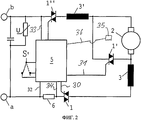
на фиг.1 и 2 - электрические схемы электродинамического тормоза для универсального электродвигателя иfigure 1 and 2 are electrical diagrams of an electrodynamic brake for a universal motor and
на фиг.3-5 - сигналограммы в виде характеристик изменения тока при работе в двигательном режиме и в режиме торможения иfigure 3-5 - waveforms in the form of characteristics of current changes during operation in motor mode and in braking mode and
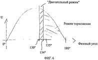
на фиг.6 - схема, иллюстрирующая работу в режиме торможения в течение полуволны сетевого напряжения.Fig.6 is a diagram illustrating operation in the braking mode during the half-wave of the mains voltage.
На фиг.1 показана электрическая схема, в которой в линии, ведущей к первому выводу а для подключения к сети, расположен первый симистор 1, включенный последовательно с универсальным электродвигателем, а параллельно якорю 2 включен второй симистор 1', перед которым последовательно с ним включен переключатель S. Якорь 2 включен между двумя обмотками 3, 3' возбуждения. Переключатель S подсоединен к одной из сторон якоря 2. Второй симистор 1' с одной своей стороны подсоединен к обеспечивающему работу в режиме торможения контакту е переключателя S, а с другой своей стороны - к другой из сторон якоря. Распознающий контакт f переключателя S соединен линией 4 с управляющей электроникой 5. Управляющая электроника 5 соединена первой управляющей линией 30 с первым симистором 1, а второй управляющей линией 31 - со вторым симистором 1'. Управляющая электроника 5 соединена далее первой питающей линией 32 с первым выводом а для подключения к сети, а второй питающей линией 33 - со вторым выводом b для подключения к сети. Кроме того, от управляющей электроники 5 к соединительной линии между шунтом 6 и первым симистором 1 проходит сигнальная линия 34. Помимо этого могут быть предусмотрены дополнительные датчики 35, прежде всего тахометр или датчик температуры универсального электродвигателя 1, которые соединены еще одной сигнальной линией 36 с управляющей электроникой 5.Figure 1 shows an electrical circuit in which, in a line leading to the first terminal a for connecting to the network, there is a
При работе в двигательном режиме переключатель S замкнут на распознающий контакт f, и поэтому работа в двигательном режиме происходит через первый симистор 1. При работе же в режиме торможения переключатель S замкнут на обеспечивающий работу в этом режиме торможения контакт е, и поэтому работа в режиме торможения происходит одновременно через первый симистор 1 и второй симистор 1'.When operating in the motor mode, the switch S is closed to the recognition contact f, and therefore, operation in the motor mode occurs through the
От применения переключателя S можно отказаться. Помимо этого с управляющей электроникой 5 может быть соединен коммутирующий элемент датчика сигналов. В данном варианте второй симистор 1' соединен с двумя выводами якоря 2. Такой переключатель датчика сигналов, предназначенный для надежного распознавания двигательного режима и режима торможения, предпочтительно имеет три вывода.Switch S can be omitted. In addition, a switching element of the signal sensor can be connected to the control electronics 5. In this embodiment, the second triac 1 'is connected to two terminals of the
Для повышения эффективности процесса торможения и прежде всего для снижения искрения под щетками при работе в режиме торможения первым и вторым симисторами 1, 1' в особенности управляет программа, которая заложена в контроллер управляющей электроники 5 и которая составлена таким образом, что предпочтительно в течение каждой полуволны сетевого напряжения сначала отпирается, т.е. переводится в проводящее состояние, первый симистор 1, чем активизируется работа в двигательном режиме. Несмотря на использование в данном случае термина "двигательный режим", поскольку соответственно выбрана подача напряжения, тем не менее при этом предпочтительно сетевое напряжение выбрано таким и прежде всего длительность его подачи выбрана настолько короткой, что не происходит никакого существенного, а предпочтительно вовсе никакого ускорения универсального электродвигателя. Благодаря этому при заданном положении щеток достигается оптимальная коммутация. Далее с заданной временной задержкой отпирается, т.е. переводится в проводящее состояние, второй симистор 1', в результате чего оба - первый 1 и второй 1' - симисторы находятся в проводящем состоянии. Вследствие этого якорь 2 оказывается замкнут накоротко через симистор 1', а ток сети протекает непосредственно через обмотку 3, 3' возбуждения и через первый и второй симисторы 1, 1'. Индуктированный ток в цепи короткозамкнутого якоря 2 протекает также через второй симистор 1'. В связи с изменением полярности поля на якоре при работе в режиме торможения по причине заданного положения щеток происходит недостаточная коммутация на якоре.To increase the efficiency of the braking process, and especially to reduce sparking under the brushes during operation in the braking mode, the first and
Поскольку предпочтительно в течение каждой полуволны при работе в режиме торможения перед фактическим режимом торможения кратковременно активизируется двигательный режим, искрение под щетками при короткозамкнутом якоре подавляется, благодаря чему уменьшается искрение на коллекторе, а тем самым и снижается износ щеток.Since it is preferable that during each half-wave when operating in the braking mode, the motor mode is briefly activated before the actual braking mode, the sparking under the brushes with a short-circuit anchor is suppressed, thereby reducing the sparking on the collector, and thereby reducing brush wear.
Временная задержка в отпирании второго симистора 1' имеет такую продолжительность, что работа в двигательном режиме предпочтительно в течение каждой полуволны при работе в режиме торможения достаточна для подавления искрения под щетками на коллекторе универсального электродвигателя, но не достаточна для сколько-нибудь существенного приведения в действие якоря 2.The time delay in unlocking the second triac 1 'has such a duration that operation in the motor mode, preferably during each half-wave during operation in the braking mode, is sufficient to suppress arcing under the brushes on the collector of the universal electric motor, but is not sufficient for any significant activation of the
Временная задержка в отпирании второго симистора 1' в течение каждой полуволны в предпочтительном варианте постоянна на протяжении всего времени торможения, т.е. в процессе торможения универсального электродвигателя 1. Однако указанная временная задержка может также иметь переменную величину, т.е. может изменяться при работе в режиме торможения. В начале работы в режиме торможения временная задержка может соответственно иметь большую величину, а затем в ходе дальнейшей работы в режиме торможения сокращаться, предпочтительно непрерывно, например, от одной полуволны к другой и достигать в конце времени торможения величины, при которой второй симистор 1' отпирается непосредственно после отпирания первого симистора 1 или одновременно с ним либо даже раньше него.The time delay in unlocking the second triac 1 'during each half-wave is preferably constant throughout the entire braking time, i.e. during braking of the universal
Универсальный электродвигатель может быть также выполнен отсоединяемым от сети с обеих своих сторон.The universal electric motor can also be made disconnected from the network on both sides.
На фиг.2 показан вариант, в котором в линии, ведущей ко второму выводу b для подключения к сети, расположен третий симистор 1''. Первый и третий симисторы 1,1'' всегда отпираются одновременно. В данном случае с управляющей электроникой 5 функционально связан сигнальный ключ S' для распознавания двигательного режима и режима торможения.Figure 2 shows a variant in which in the line leading to the second terminal b for connecting to the network, there is a third triac 1 ''. The first and third 1.1 '' triacs are always unlocked simultaneously. In this case, a signal switch S 'is functionally connected to the control electronics 5 for recognizing the motor mode and the braking mode.
Второй симистор 1', который включен параллельно якорю 2, может контролироваться шунтом 6. В том случае, когда после включения универсального электродвигателя обнаруживается протекание тока слишком большой силы, второй симистор 1' предположительно находится в проводящем состоянии, и универсальный электродвигатель сразу же отсоединяется от сети. В подобном случае может подаваться предупредительный мигающий световой сигнал.The second triac 1 ', which is connected in parallel with the
В описанных выше вариантах симисторы использовались в качестве полупроводниковых ключей. В зависимости от выбранного варианта возможно использование и иных ключей, прежде всего полупроводниковых ключей, для управления подачей напряжения и тока на универсальный электродвигатель в целях обеспечения его работы в двигательном режиме и в режиме торможения.In the above embodiments, triacs were used as semiconductor switches. Depending on the chosen option, it is possible to use other keys, primarily semiconductor switches, to control the supply of voltage and current to a universal electric motor in order to ensure its operation in motor mode and in braking mode.
Описанный выше электродинамический тормоз отличается прежде всего хорошей коммутацией тока под щетками на коллекторе универсального электродвигателя при работе в режиме торможения. Такое особое преимущество достигается благодаря тому, что включенный параллельно якорю 2 симистор 1' отпирается с особой временной задержкой относительно первого симистора 1, включенного последовательно с универсальным электродвигателем.The electrodynamic brake described above is distinguished primarily by good current switching under the brushes on the manifold of a universal electric motor when operating in braking mode. This particular advantage is achieved due to the fact that the triac 1 'connected in parallel with the
Описанный выше способ более подробно рассмотрен ниже со ссылкой на фиг.3-5, при этом в предпочтительном варианте при работе в режиме торможения для управления симисторами 1,1' всегда используется одна и та же таблица заложенной в контроллер программы для кривой фазовых углов.The method described above is discussed in more detail below with reference to FIGS. 3-5, while in the preferred embodiment, when operating in the braking mode, the same program table for the phase angle curve is always used to control the 1,1 ”triacs.
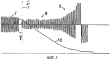
На фиг.3 показана сигналограмма, отражающая характеристику изменения тока при работе в режиме торможения. Работа универсального электродвигателя в режиме холостого хода обозначена полными волнами 7 с фазовой отсечкой и с частотой, равной сетевой частоте. После короткой паузы Р сразу начинается работа в режиме торможения В, при этом первый и второй симисторы 1,1' одновременно отперты по команде программы, заложенной в контроллер управляющей электроники 5. В течение первых двух третей 8 времени торможения потребление тока обмоткой 3 возбуждения остается приблизительно одинаковым. По этой причине в начале работы в режиме торможения происходит интенсивное искрение под щетками, из-за чего щетки обгорают, а коллектор повреждается. В течение последней трети 9 времени торможения потребление тока обмоткой возбуждения незначительно возрастает.Figure 3 shows the waveform, reflecting the characteristic change in current during operation in braking mode. The operation of the universal motor in idle is indicated by the
Форма линии, которой на чертеже обозначена кривая 10 изменения частоты вращения (или скоростная характеристика), свидетельствует о том, что в начале работы в режиме торможения оно является слишком резким, а в конце - слишком слабым.The shape of the line, which shows the
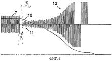
На фиг.4 показана сигналограмма, отражающая характеристику изменения тока при работе в режиме торможения В, в котором отпирание второго симистора 1' произошло с соответствующей временной задержкой после отпирания первого симистора 1, благодаря чему предпочтительно в течение каждой полуволны сетевого тока сначала происходит работа в двигательном режиме, а затем - в режиме торможения.Figure 4 shows a waveform reflecting the characteristic of the current change during operation in braking mode B, in which the unlocking of the second triac 1 'occurred with a corresponding time delay after unlocking the
В начале 11 времени торможения потребление тока обмоткой 3 возбуждения существенно ниже по сравнению с фиг.3 и в дальнейшем слегка возрастает, а в последней трети 12 времени торможения значительно возрастает.At the beginning of the 11 braking time, the current consumption of the field winding 3 is substantially lower compared to FIG. 3 and slightly increases in the future, and in the last third 12 of the braking time it increases significantly.
Благодаря временной задержке в отпирании второго симистора 1' коммутация на коллекторе универсального электродвигателя явно улучшается, а обгорание щеток уже значительно уменьшается. Форма кривой 10 изменения частоты вращения свидетельствует о том, что в начале работы в режиме торможения оно слабее, а затем усиливается.Due to the time delay in unlocking the second triac 1 ', commutation on the collector of a universal electric motor is clearly improved, and the burning of brushes is already significantly reduced. The shape of the
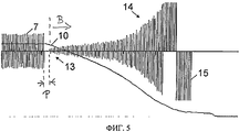
На фиг.5 показана сигналограмма, отражающая характеристику изменения тока при работе в режиме торможения, в котором отпирание второго симистора 1' произошло с оптимальной временной задержкой после отпирания первого симистора 1, благодаря чему предпочтительно в течение каждой полуволны сетевого тока сначала происходит достаточная для обеспечения хорошей коммутации тока под щетками работа в двигательном режиме, а затем происходит работа в режиме торможения, при этом продолжительность такой временной задержки выбрана такой, что коммутация тока под щетками при переходе с работы в двигательном режиме на работу в режиме торможения перемещается со сбегающего края щеток на их набегающий край, благодаря чему значительно уменьшается искрение под щетками, а также выбрана такой, что при работе в режиме торможения якорь в принципе не приводится в действие.Figure 5 shows a waveform reflecting the characteristic of the current change during operation in the braking mode, in which the unlocking of the second triac 1 'occurred with an optimal time delay after unlocking the
Согласно фиг.5 в начале 13 времени торможения потребление тока обмоткой 3 возбуждения еще ниже, чем на фиг.4, и в дальнейшем непрерывно умеренно возрастает, а в последней трети 14 времени торможения для ускорения процесса торможения соответственно возрастает до высокого уровня. В конце времени торможения на обмотку возбуждения подаются пакеты 15 полуволн.According to Fig. 5, at the beginning of the
Форма кривой 10 изменения частоты вращения свидетельствует о достижении оптимальной тормозной характеристики. В начале работы в режиме торможения оно начинается плавно и далее непрерывно сверхпропорционально усиливается, а в конце работы в режиме торможения вновь становится плавным.The shape of the
Благодаря временной задержке в отпирании второго симистора 1' можно использовать нерегулируемый режим торможения. Поэтому следует применять неизменную кривую фазовых углов, задаваемую таблицей, содержащейся в программе, заложенной в контроллер, поскольку при регулируемом режиме торможения изменение тормозного тока могло бы носить неспокойный характер, а искрение под щетками могло бы по этой причине усиливаться.Due to the time delay in unlocking the second triac 1 ', an unregulated braking mode can be used. Therefore, an invariable curve of the phase angles, given by the table contained in the program embedded in the controller, should be applied, since with an adjustable braking mode, the change in the braking current could be unstable, and the sparking under the brushes could increase for this reason.
Для возможности поддержания скачков тока при работе в режиме торможения на низком уровне и уменьшения тем самым искрения под щетками шаг изменения фазового угла, например, от одной полуволны к другой в предпочтительном варианте может составлять менее 1%.In order to be able to maintain current surges when operating in the braking mode at a low level and thereby reduce sparking under the brushes, the step of changing the phase angle, for example, from one half-wave to another, in the preferred embodiment, can be less than 1%.
По мере укорачивания щеток их давление на коллектор на заданное время торможения может оказаться уже недостаточным из-за уже недостаточного для этого напряжения короткозамкнутого якоря.As the brushes are shortened, their pressure on the collector for a given braking time may already be insufficient due to the already shorted voltage of the short-circuited armature.
С целью вновь обеспечить возможность соблюдения времени торможения программа, заложенная в контроллер управляющей электроники 5, переключается на еще одну таблицу для кривой фазовых углов с меньшей фазовой отсечкой полуволн переменного напряжения сети.In order to again ensure the possibility of observing the braking time, the program embedded in the control electronics controller 5 switches to another table for the phase angle curve with a smaller phase cut-off of half-waves of the alternating voltage of the network.
Достижение достаточного тормозного эффекта можно определять либо с помощью шунта, либо путем измерения частоты вращения.The achievement of a sufficient inhibitory effect can be determined either by using a shunt, or by measuring the speed.
Электродинамический тормоз в другом варианте может также работать на постоянном токе.The electrodynamic brake in another embodiment may also operate on direct current.
Программа, заложенная в контроллер управляющей электроники, в предпочтительном варианте содержит другие таблицы для кривых фазовых углов с уменьшающейся от одной таблицы к другой фазовой отсечкой полуволн сетевого напряжения.The program incorporated in the control electronics controller, in a preferred embodiment, contains other tables for phase angle curves with a phase-cut half-wave of the mains voltage decreasing from one table to another.
Помимо этого тормозная характеристика в предпочтительном варианте рассчитана таким образом, что в начале работы в режиме торможения оно начинается плавно и далее непрерывно сверхпропорционально усиливается, а в конце работы в режиме торможения вновь становится плавным.In addition, the braking characteristic is preferably designed in such a way that at the beginning of operation in the braking mode it starts smoothly and then continuously superproportionally amplifies, and at the end of operation in the braking mode it again becomes smooth.
На фиг.6 схематично показана полуволна сетевого напряжения в функции фазового угла сетевого напряжения на выводах a, b для подключения к сети при работе универсального электродвигателя в режиме торможения. Основная идея изобретения заключается в том, чтобы обеспечивать щадящее торможение универсального электродвигателя с помощью сетевого напряжения. При этом при работе в режиме торможения сначала кратковременно включается двигательный режим, а затем происходит переключение на собственно режим торможения. В рассматриваемом примере при фазовом угле, равном 130°, первый ключ 1 (или коммутационный аппарат) переходит в проводящее (открытое) состояние, а второй ключ 1' все еще остается в непроводящем (закрытом) состоянии. Затем при следующем фазовом угле, равном 134°, второй ключ 1' также переходит в проводящее состояние, в результате чего на универсальный электродвигатель оказывается фактическое тормозное действие. В промежутке времени между фазовыми углами 130° и 134° кратковременно включается двигательный режим. После фазового угла, равного 134°, происходит работа только в режиме торможения, который заканчивается, например, при фазовом угле, равном 180°.Figure 6 schematically shows the half-wave of the mains voltage as a function of the phase angle of the mains voltage at terminals a, b for connecting to the network when the universal motor is in braking mode. The main idea of the invention is to provide gentle braking of a universal electric motor using mains voltage. In this case, when operating in the braking mode, the motor mode is first briefly turned on, and then the braking mode is switched on. In the considered example, at a phase angle equal to 130 °, the first switch 1 (or switching device) goes into a conducting (open) state, and the second switch 1 'still remains in a non-conducting (closed) state. Then, at the next phase angle equal to 134 °, the second switch 1 'also goes into a conducting state, as a result of which the actual braking effect is exerted on the universal motor. In the interval between the phase angles of 130 ° and 134 °, the motor mode is briefly activated. After a phase angle of 134 °, only the braking mode occurs, which ends, for example, with a phase angle of 180 °.
В зависимости от выбранного варианта фазовый угол включения, а тем самым и момент включения первого ключа с его переходом в проводящее состояние в процессе торможения варьируется в зависимости от различных параметров, таких, например, как частота вращения вала универсального электродвигателя, его температура, требуемая продолжительность торможения и/или требуемое продление срока эксплуатации щеток коллектора (степень их "щажения"). Помимо этого варьируется и временная задержка между моментом включения первого ключа, т.е. моментом его перехода в проводящее состояние, для кратковременного инициирования двигательного режима и моментом включения второго ключа, т.е. моментом его перехода в проводящее состояние, для инициирования режима торможения.Depending on the chosen option, the phase angle of inclusion, and thereby the moment of switching on the first key with its transition to the conducting state during braking, varies depending on various parameters, such as, for example, the speed of the universal motor shaft, its temperature, the required braking time and / or the required extension of the life of the collector brushes (the degree of their “sparing”). In addition, the time delay between the moment the first key is turned on varies, i.e. the moment of its transition to a conducting state, for short-term initiation of the motor mode and the moment of switching on the second key, i.e. moment of its transition to a conducting state, to initiate braking mode.
Временная задержка между моментами включения первого и второго ключей может, например, составлять от одной микросекунды до одной миллисекунды. Так, например, такая временная задержка может составлять либо от 1 до 5 мкс, либо от 5 до 20 мкс, либо от 20 до 50 мкс, либо от 50 до 100 мкс. Помимо этого такая временная задержка может составлять от 100 до 300 мкс. В зависимости от варианта можно использовать временную задержку меньшей или большей продолжительности.The time delay between the moments when the first and second keys are turned on can, for example, be from one microsecond to one millisecond. So, for example, such a time delay can be either from 1 to 5 μs, or from 5 to 20 μs, or from 20 to 50 μs, or from 50 to 100 μs. In addition, such a time delay can be from 100 to 300 μs. Depending on the variant, a time delay of shorter or longer duration can be used.
В простом варианте временная задержка между моментами отпирания первого и второго ключей для кратковременной активизации двигательного режима и последующей активизации режима торможения может быть постоянной на протяжении всего процесса торможения.In a simple embodiment, the time delay between the moments of unlocking the first and second keys for short-term activation of the motor mode and subsequent activation of the braking mode can be constant throughout the entire braking process.
В другом варианте временная задержка между моментом включения первого ключа для кратковременной активизации двигательного режима и моментом включения второго ключа для активизации режима торможения может в процессе торможения зависеть от тех или иных параметров универсального электродвигателя, например, его температуры, частоты вращения, электрических свойств, таких как сопротивление R и индуктивность L, и от сетевого напряжения.In another embodiment, the time delay between the moment the first key is turned on for short-term activation of the motor mode and the moment the second key is turned on to activate the braking mode may depend on certain parameters of the universal motor, for example, its temperature, speed, electrical properties, such as resistance R and inductance L, and from mains voltage.
Так, например, временная задержка может зависеть от сетевого напряжения в момент включения первого ключа и/или от частоты вращения вала универсального электродвигателя и/или от его температуры. Для этого в предпочтительном варианте в памяти данных сохранены полученные экспериментальным путем таблицы или параметрические кривые, к которым обращается управляющая электроника.So, for example, the time delay may depend on the mains voltage at the moment the first switch is turned on and / or on the speed of the universal motor shaft and / or on its temperature. For this, in a preferred embodiment, tables or parametric curves obtained by the control electronics are accessed in the data memory by experiment.
Температуру универсального электродвигателя и частоту вращения его вала можно определять соответствующими датчиками 35 либо оценивать, соответственно вычислять на основании рабочих параметров, таких, например, как ток и напряжение.The temperature of the universal motor and the frequency of rotation of its shaft can be determined by the corresponding
В зависимости от выбранного варианта универсальный электродвигатель можно в течение каждой полуволны сетевого напряжения переводить на работу в режиме торможения с кратковременной предшествующей ему работой в двигательном режиме, как это рассмотрено выше со ссылкой на фиг.6. В зависимости от выбранного варианта работа в двигательном режиме может при этом осуществляться перед переключением на работу в фактическом режиме торможения, например только в течение части полуволн.Depending on the chosen option, the universal electric motor can be switched over to operation in the braking mode with the short-term preceding operation in the motor mode during each half-wave of the mains voltage, as discussed above with reference to FIG. 6. Depending on the selected option, operation in the motor mode may be carried out before switching to work in the actual braking mode, for example, only during part of the half-waves.
Управляющая электроника выполнена в виде контроллера с соответствующим программным обеспечением для управления первым и вторым ключами. Для этого предусмотрена далее память, в которой хранятся управляющая программа и управляющая информация, например таблицы фазовой отсечки ключей, т.е. значения фазовых углов включения и выключения первого ключа и включения и выключения второго ключа, соответствующие режиму торможения, проиллюстрированному на фиг.6. В такой памяти сохранены прежде всего таблицы и параметрические кривые для фазовых углов, при которых должно происходить включение, соответственно выключение первого ключа и/или второго ключа. Такие таблицы и параметрические кривые могут при этом зависеть от параметров универсального электродвигателя и/или от сетевого напряжения. Временная задержка в отпирании второго ключа после отпирания первого ключа при работе в режиме торможения может прежде всего зависеть от сетевого напряжения в момент включения первого ключа и/или от частоты вращения вала универсального электродвигателя и/или от его температуры. Для этого в памяти сохранены соответствующие таблицы и/или параметрические кривые, которые были получены, например, экспериментальным путем.The control electronics is made in the form of a controller with appropriate software for managing the first and second keys. For this, a memory is further provided in which the control program and control information are stored, for example, phase-cut-off tables of keys, i.e. the values of the phase angles of turning on and off the first key and turning on and off the second key, corresponding to the braking mode illustrated in Fig.6. In such a memory, first of all, tables and parametric curves are stored for phase angles at which the first key and / or the second key must be turned on, respectively turned off. Such tables and parametric curves may depend on the parameters of the universal motor and / or on the mains voltage. The time delay in unlocking the second key after unlocking the first key during operation in the braking mode may primarily depend on the mains voltage at the moment the first key is turned on and / or on the speed of the universal motor shaft and / or on its temperature. For this, the corresponding tables and / or parametric curves are stored in the memory, which were obtained, for example, experimentally.
Помимо этого в памяти можно сохранять данные, которые задают изменение фазового угла от одной полуволны к другой. Так, например, изменение фазового угла от одной полуволны к следующей для перехода первого ключа в проводящее состояние и/или для перехода второго ключа в проводящее состояние может быть ограничено максимальным значением, например, в один процент.In addition, data that sets the phase angle change from one half-wave to another can be stored in memory. So, for example, a change in the phase angle from one half-wave to the next for the first key to switch to the conducting state and / or for the second key to switch to the conducting state can be limited to a maximum value, for example, one percent.
Из приведенных на фиг.3-5 диаграмм вытекает, что в конце работы в режиме торможения последовательно следуют пакеты полуволн напряжения разной полярности. В соответствии с этим для заданных временных интервалов или заданного количества полуволн используются, например, только положительные полуволны сетевого напряжения в целях торможения электродвигателя с использованием двигательного режима и режима торможения. Затем используют пакет отрицательных полуволн сетевого напряжения в целях торможения универсального электродвигателя путем кратковременной активизации двигательного режима и последующей активизации режима торможения, как это рассмотрено выше со ссылкой на фиг.6.From the diagrams shown in FIGS. 3-5, it follows that at the end of operation in the braking mode, packets of half-waves of voltage of different polarity successively follow. Accordingly, for a given time interval or a given number of half-waves, for example, only positive half-waves of the mains voltage are used to brake the electric motor using the motor mode and the braking mode. Then use a package of negative half-waves of the mains voltage in order to brake the universal electric motor by briefly activating the motor mode and then activating the braking mode, as discussed above with reference to Fig.6.
Claims (15)
Applications Claiming Priority (5)
| Application Number | Priority Date | Filing Date | Title |
|---|---|---|---|
| DE102009060139.2 | 2009-12-23 | ||
| DE200910060139 DE102009060139A1 (en) | 2009-12-23 | 2009-12-23 | Electro-dynamic braking device for universal motor, has winding fed over triacs during brake operation, where motor operation during brake operation is sufficient for commutation at motor collector and is not sufficient to drive armature |
| DE102010004311.7 | 2010-01-11 | ||
| DE102010004311A DE102010004311A1 (en) | 2010-01-11 | 2010-01-11 | Electrodynamic braking device for universal motor, has control electronic unit simulating brake operation and motor operation, switch conductively switched, and other switch conductively switched with predetermined time delay |
| PCT/EP2010/070457 WO2011076827A2 (en) | 2009-12-23 | 2010-12-22 | Braking device for a universal motor |
Publications (2)
| Publication Number | Publication Date |
|---|---|
| RU2012131272A RU2012131272A (en) | 2014-01-27 |
| RU2553674C2 true RU2553674C2 (en) | 2015-06-20 |
Family
ID=44064659
Family Applications (1)
| Application Number | Title | Priority Date | Filing Date |
|---|---|---|---|
| RU2012131272/07A RU2553674C2 (en) | 2009-12-23 | 2010-12-22 | Brake for universal electric motor |
Country Status (6)
| Country | Link |
|---|---|
| US (1) | US9590538B2 (en) |
| EP (1) | EP2517349B1 (en) |
| JP (1) | JP5645967B2 (en) |
| CN (1) | CN102742146B (en) |
| RU (1) | RU2553674C2 (en) |
| WO (1) | WO2011076827A2 (en) |
Families Citing this family (10)
| Publication number | Priority date | Publication date | Assignee | Title |
|---|---|---|---|---|
| DE102012205728A1 (en) | 2012-04-05 | 2013-10-10 | Robert Bosch Gmbh | Method and device for the electrodynamic braking of a universal motor |
| DE102012205876A1 (en) | 2012-04-11 | 2013-10-17 | Robert Bosch Gmbh | Method and device for the electrodynamic braking of a universal motor |
| US9218075B2 (en) * | 2012-11-01 | 2015-12-22 | Immersion Corporation | Haptically-enabled system with braking |
| US9614466B2 (en) | 2014-05-20 | 2017-04-04 | Black & Decker Inc. | Electronic braking for a universal motor in a power tool |
| EP3224941B1 (en) * | 2014-11-24 | 2021-01-13 | Robert Bosch GmbH | Motor braking system and method for power tools |
| CN104617823A (en) * | 2015-01-12 | 2015-05-13 | 金懋实业有限公司 | Damp control circuit of motor magnetic loop and control method of damp control circuit |
| US11047528B2 (en) | 2016-02-12 | 2021-06-29 | Black & Decker Inc. | Electronic braking for a power tool having a brushless motor |
| CN107294466A (en) * | 2016-04-05 | 2017-10-24 | 德昌电机(深圳)有限公司 | Electric tool and its motor driven systems |
| CN109120187B (en) * | 2018-06-05 | 2021-04-27 | 东南大学 | Controller of electromagnetic braking device |
| CN109450298B (en) * | 2018-11-29 | 2024-04-30 | 惠州拓邦电气技术有限公司 | Electronic brake circuit, electric appliance and method |
Citations (6)
| Publication number | Priority date | Publication date | Assignee | Title |
|---|---|---|---|---|
| SU544573A1 (en) * | 1975-11-04 | 1977-01-30 | Предприятие П/Я Г-4868 | Device for electrodynamic braking of a traction motor |
| SU1707726A1 (en) * | 1989-12-05 | 1992-01-23 | Харьковский Институт Инженеров Железнодорожного Транспорта Им.С.М.Кирова | Direct current drive |
| RU2007835C1 (en) * | 1992-02-17 | 1994-02-15 | Московский Институт Инженеров Железнодорожного Транспорта | Electric drive for hand tool |
| RU2168259C1 (en) * | 2000-02-14 | 2001-05-27 | Зао "Кросна-Электра" | Direct-current drive |
| DE10317636A1 (en) * | 2003-04-17 | 2004-11-25 | Robert Bosch Gmbh | Braking device for an electric motor |
| US6998804B2 (en) * | 2002-07-23 | 2006-02-14 | C. & E. Fein Gmbh & Co. Kg | Electric motor with electronic brake |
Family Cites Families (11)
| Publication number | Priority date | Publication date | Assignee | Title |
|---|---|---|---|---|
| NL7109226A (en) * | 1971-07-03 | 1973-01-05 | ||
| JPS5992785A (en) | 1982-11-16 | 1984-05-29 | Fuji Electric Co Ltd | Brake device for motor |
| IT1258950B (en) | 1992-06-05 | 1996-03-11 | Black & Decker Inc | CONTROLLED BRAKING DEVICE FOR ELECTRIC MOTORS, IN PARTICULAR OF PORTABLE TOOLS |
| DE4333064A1 (en) * | 1993-09-29 | 1995-03-30 | Scintilla Ag | Brake circuit for a universal motor |
| AU4334699A (en) | 1998-06-05 | 1999-12-20 | Milwaukee Electric Tool Corporation | Braking and control circuit for electric power tools |
| DE19843106B4 (en) * | 1998-09-21 | 2005-08-18 | Ebm-Papst Mulfingen Gmbh & Co. Kg | System for controlling the speed of AC motors |
| DE19932742C1 (en) | 1999-01-07 | 2000-09-21 | Hans Hermann Rottmerhusen | Network brake device for an electric hand tool |
| JP2002153087A (en) | 2000-11-13 | 2002-05-24 | Max Co Ltd | Ac motor drive circuit |
| US8280569B2 (en) * | 2004-12-09 | 2012-10-02 | General Electric Company | Methods and systems for improved throttle control and coupling control for locomotive and associated train |
| ES1065745Y (en) * | 2007-06-21 | 2008-01-16 | Coprecitec Sl | WASHER CONTROL DEVICE |
| CN102484447B (en) * | 2009-03-03 | 2015-05-06 | 罗伯特·博世有限公司 | Electrodynamic braking device for universal motor |
-
2010
- 2010-12-22 EP EP10796054.4A patent/EP2517349B1/en active Active
- 2010-12-22 CN CN201080063277.9A patent/CN102742146B/en active Active
- 2010-12-22 US US13/518,799 patent/US9590538B2/en active Active
- 2010-12-22 RU RU2012131272/07A patent/RU2553674C2/en not_active IP Right Cessation
- 2010-12-22 JP JP2012545314A patent/JP5645967B2/en active Active
- 2010-12-22 WO PCT/EP2010/070457 patent/WO2011076827A2/en active Application Filing
Patent Citations (7)
| Publication number | Priority date | Publication date | Assignee | Title |
|---|---|---|---|---|
| SU544573A1 (en) * | 1975-11-04 | 1977-01-30 | Предприятие П/Я Г-4868 | Device for electrodynamic braking of a traction motor |
| SU1707726A1 (en) * | 1989-12-05 | 1992-01-23 | Харьковский Институт Инженеров Железнодорожного Транспорта Им.С.М.Кирова | Direct current drive |
| RU2007835C1 (en) * | 1992-02-17 | 1994-02-15 | Московский Институт Инженеров Железнодорожного Транспорта | Electric drive for hand tool |
| RU2168259C1 (en) * | 2000-02-14 | 2001-05-27 | Зао "Кросна-Электра" | Direct-current drive |
| US6998804B2 (en) * | 2002-07-23 | 2006-02-14 | C. & E. Fein Gmbh & Co. Kg | Electric motor with electronic brake |
| DE10317636A1 (en) * | 2003-04-17 | 2004-11-25 | Robert Bosch Gmbh | Braking device for an electric motor |
| US7071645B2 (en) * | 2003-04-17 | 2006-07-04 | Robert Bosch Gmbh | Braking device for an electric motor, electrical apparatus provided with the braking device, and a method of braking |
Also Published As
| Publication number | Publication date |
|---|---|
| EP2517349A2 (en) | 2012-10-31 |
| RU2012131272A (en) | 2014-01-27 |
| US9590538B2 (en) | 2017-03-07 |
| EP2517349B1 (en) | 2014-03-26 |
| WO2011076827A3 (en) | 2012-08-16 |
| WO2011076827A9 (en) | 2011-10-20 |
| JP2013516152A (en) | 2013-05-09 |
| WO2011076827A2 (en) | 2011-06-30 |
| US20120319627A1 (en) | 2012-12-20 |
| JP5645967B2 (en) | 2014-12-24 |
| CN102742146B (en) | 2015-12-09 |
| CN102742146A (en) | 2012-10-17 |
Similar Documents
| Publication | Publication Date | Title |
|---|---|---|
| RU2553674C2 (en) | Brake for universal electric motor | |
| RU2528413C2 (en) | Electrodynamic decelerator for universal motor | |
| CN100454747C (en) | Excitation circuit and control method for flux switching motor | |
| JP2013516152A5 (en) | ||
| CN100379139C (en) | Excitation circuit and control method for flux switching motor | |
| US6448727B1 (en) | Mains braking device for a line-powered power tool | |
| JPH11501496A (en) | General-purpose motor braking circuit | |
| CN205285922U (en) | Use reliable juice extractor | |
| GB2400990A (en) | Braking device for an electric motor | |
| US10892691B2 (en) | Control circuit and power tool | |
| KR101119549B1 (en) | Starting system for a single-phase induction motor | |
| US4560913A (en) | Sparkless circuit for low horsepower electronic motor brake | |
| CN104617831A (en) | Driving device for single-phase series excitation commutator motor | |
| US4812728A (en) | Electro magnetic braking circuit for small single phase induction motors | |
| RU2054788C1 (en) | Three-phase induction-motor drive supplied with power from single-phase line | |
| CN208028798U (en) | brushless direct current motor drive circuit and system | |
| RU1791950C (en) | Method of control over d c motor of valve adapted to electric power | |
| SU731537A1 (en) | Device for control of single-phase induction motor | |
| SU1683164A1 (en) | Dc electric drive | |
| US20200266733A1 (en) | Method for controlling brushless motor | |
| PL175461B1 (en) | Method of controlling operation of a reluctance motor | |
| JPS6028236B2 (en) | braking device |
Legal Events
| Date | Code | Title | Description |
|---|---|---|---|
| MM4A | The patent is invalid due to non-payment of fees |
Effective date: 20201223 |