JP5645967B2 - Braking device for universal motor - Google Patents
Braking device for universal motor Download PDFInfo
- Publication number
- JP5645967B2 JP5645967B2 JP2012545314A JP2012545314A JP5645967B2 JP 5645967 B2 JP5645967 B2 JP 5645967B2 JP 2012545314 A JP2012545314 A JP 2012545314A JP 2012545314 A JP2012545314 A JP 2012545314A JP 5645967 B2 JP5645967 B2 JP 5645967B2
- Authority
- JP
- Japan
- Prior art keywords
- switch
- braking
- motor
- braking operation
- universal motor
- Prior art date
- Legal status (The legal status is an assumption and is not a legal conclusion. Google has not performed a legal analysis and makes no representation as to the accuracy of the status listed.)
- Active
Links
- 238000004804 winding Methods 0.000 claims description 22
- 230000005520 electrodynamics Effects 0.000 claims description 19
- 238000000034 method Methods 0.000 claims description 16
- 230000001419 dependent effect Effects 0.000 claims description 4
- 230000003213 activating effect Effects 0.000 claims 4
- 230000008569 process Effects 0.000 description 7
- 230000009471 action Effects 0.000 description 4
- 230000001133 acceleration Effects 0.000 description 3
- 230000008901 benefit Effects 0.000 description 3
- 230000008859 change Effects 0.000 description 3
- 238000010586 diagram Methods 0.000 description 3
- 230000004044 response Effects 0.000 description 3
- 230000004913 activation Effects 0.000 description 2
- 239000004065 semiconductor Substances 0.000 description 2
- 230000006978 adaptation Effects 0.000 description 1
- 230000015572 biosynthetic process Effects 0.000 description 1
- 238000002485 combustion reaction Methods 0.000 description 1
- 230000007423 decrease Effects 0.000 description 1
- 230000001627 detrimental effect Effects 0.000 description 1
- 238000010304 firing Methods 0.000 description 1
- 230000009467 reduction Effects 0.000 description 1
- 230000007704 transition Effects 0.000 description 1
- 230000001960 triggered effect Effects 0.000 description 1
- 238000011144 upstream manufacturing Methods 0.000 description 1
Images


Classifications
-
- H—ELECTRICITY
- H02—GENERATION; CONVERSION OR DISTRIBUTION OF ELECTRIC POWER
- H02P—CONTROL OR REGULATION OF ELECTRIC MOTORS, ELECTRIC GENERATORS OR DYNAMO-ELECTRIC CONVERTERS; CONTROLLING TRANSFORMERS, REACTORS OR CHOKE COILS
- H02P3/00—Arrangements for stopping or slowing electric motors, generators, or dynamo-electric converters
- H02P3/06—Arrangements for stopping or slowing electric motors, generators, or dynamo-electric converters for stopping or slowing an individual dynamo-electric motor or dynamo-electric converter
- H02P3/18—Arrangements for stopping or slowing electric motors, generators, or dynamo-electric converters for stopping or slowing an individual dynamo-electric motor or dynamo-electric converter for stopping or slowing an ac motor
- H02P3/22—Arrangements for stopping or slowing electric motors, generators, or dynamo-electric converters for stopping or slowing an individual dynamo-electric motor or dynamo-electric converter for stopping or slowing an ac motor by short-circuit or resistive braking
-
- H—ELECTRICITY
- H02—GENERATION; CONVERSION OR DISTRIBUTION OF ELECTRIC POWER
- H02P—CONTROL OR REGULATION OF ELECTRIC MOTORS, ELECTRIC GENERATORS OR DYNAMO-ELECTRIC CONVERTERS; CONTROLLING TRANSFORMERS, REACTORS OR CHOKE COILS
- H02P25/00—Arrangements or methods for the control of AC motors characterised by the kind of AC motor or by structural details
- H02P25/02—Arrangements or methods for the control of AC motors characterised by the kind of AC motor or by structural details characterised by the kind of motor
- H02P25/10—Commutator motors, e.g. repulsion motors
- H02P25/14—Universal motors
Description
本発明は、請求項1によるユニバーサルモータ用の制動装置および請求項13による制動方法に関する。
The invention relates to a braking device for a universal motor according to
電気力学的制動装置は種々の設計で公知である。 Electrodynamic braking devices are known in various designs.
特許文献1は、ユニバーサルモータ用の制動および調整回路を開示する。この回路では、一方でモータを動作するための第1のスイッチング手段(トライアック)がモータと直列に接続され、他方でモータを制動するための第2のスイッチング手段(トライアック)が、磁界巻線の間に配置された電機子に並列に接続されている。モータ動作中は電機子に並列の第2のスイッチング手段には通電されず、制動動作中には第1のスイッチング手段と第2のスイッチング手段の両方が作動される。
特許文献2は、ユニバーサルモータ用の制動装置を開示する。ここでは磁界巻線および回転子巻線と電源とを接続および/または遮断するために複数のスイッチング手段が使用される。これらのスイッチング手段は複数の位置を有し、第1の位置では回転子巻線と磁界巻線が電源に接続され、第2の位置では回転子巻線が短絡され、電源は磁界巻線にだけ接続される。
特許文献3は、ユニバーサルモータ用の制動装置を開示する。この制動装置では制動動作中に電機子巻線を短絡するために短絡スイッチ(トライアック)が設けられており、短絡スイッチは切り替え状態を検出するために制御入力端を有する。短絡スイッチの制御入力端は、制動動作中にブラシ発火を回避するために短絡スイッチの位相角制御を行うべく制御ユニットと接続されている。
本発明の基礎とする課題は、効率的で安価な電気力学的制動装置またはユニバーサルモータのための制動方法を提供することであり、これにより好ましくはブラシ発火が低減され、ブラシ磨耗も少ない良好な制動が達成されるようにすることである。 The problem underlying the present invention is to provide an efficient and inexpensive braking method for an electrodynamic braking device or universal motor, which preferably reduces brush ignition and reduces brush wear. To ensure that braking is achieved.
この課題は請求項1および13の特徴によって解決される。本発明のさらなる実施形態は、従属請求項および明細書から明らかである。
This problem is solved by the features of
本発明の利点は以下のことに有り、すなわち、ユニバーサルモータ用の電気力学的制動装置に、モータ動作を制動動作に切り替えるための装置が設けられており、制動動作中にはユニバーサルモータの界磁巻線に第1と第2のスイッチを介して電源から給電され、ユニバーサルモータの電機子は第2のスイッチを介して短絡され、制御電子回路が設けられており、該制御電子回路は、制動動作中に好ましくは電源電圧の各半波内で短時間だけモータ動作とその後の制動動作が行われるように構成されており、第2のスイッチに所定の遅延時間を以て第2のスイッチが導通状態に切り換えられる。このようにしてユニバーサルモータのための改善された制動を実施することができる。 The advantages of the present invention are as follows: an electromechanical braking device for a universal motor is provided with a device for switching the motor operation to a braking operation. The winding is fed from the power source via the first and second switches, the armature of the universal motor is short-circuited via the second switch, and the control electronic circuit is provided, During operation, the motor operation and the subsequent braking operation are preferably performed for a short time within each half wave of the power supply voltage, and the second switch is in a conductive state with a predetermined delay time. Can be switched to . In this way improved braking for the universal motor can be implemented.
別の実施形態では、半波内における第2のスイッチの作動のための遅延時間が、先行して行われたモータ動作によってユニバーサルモータの集電子でのブラシ発火が低減されるように設定されている。 In another embodiment, the delay time for the operation of the second switch in Han'naminai is, brush fire in the current collector of the universal motor is set to be reduced by a motor operations performed by previously row Tei Ru.
制動装置の別の実施形態では、遅延時間は1μsから1msの間である。この値範囲が有利であることが証明されている。実現形態に依存して、より短い時間またはより長い時間を使用することもできる。 In another embodiment of the braking device, the delay time is between 1 μs and 1 ms. This value range has proven advantageous. Depending on the implementation, shorter or longer times may be used.
制動装置の別の実施形態では、第1のスイッチの後の第2のスイッチの作動のための遅延時間は、全制動の間で一定である。 In another embodiment of the brake system, the delay time for the operation of the second switch after the first switch is a constant between the total braking.
制動装置の別の実施形態では、第1のスイッチの後の第2のスイッチの作動のための遅延時間は、制動動作中にはユニバーサルモータのパラメータと電源電圧に依存する。これによって、より正確に適合した制動が達成される。とりわけ制動時間および集電子、とりわけブラシの負荷を最適化することができる。 In another embodiment of the brake system, the delay time for the operation of the second switch after the first switch is dependent on the parameters and the power supply voltage of the universal motor during braking operation. This achieves a more precisely adapted braking. In particular, the braking time and current collection, in particular the brush load, can be optimized.
制動装置の別の実施形態では、第1のスイッチの後の第2のスイッチの作動のための遅延時間は、制動動作中には第1のスイッチの切り替え時点での電源電圧および/またはユニバーサルモータの回転数および/もしくはユニバーサルモータの温度に依存する。この別の実施形態によれば、制動時間および/または集電子、とりわけブラシの負荷低減の最適化のための、制動過程のより良好な適合が可能になる。 In another embodiment of the brake system, the delay time for the operation of the second switch after the first switch, during the braking operation power supply voltage and / or a universal motor by switching time of the first switch Depending on the number of revolutions and / or the temperature of the universal motor. Lever by this alternative embodiment, the braking time and / or the current collector, especially for optimizing the load reduction of the brush allows better adaptation of the braking process.
制動装置の別の実施形態では、制動動作の開始時における第2のスイッチの作動のための遅延時間は、制動動作のさらなる経過において短くなり、とりわけ制動動作の終了時にはゼロになるか、またはとりわけ第2のスイッチは第1のスイッチの前に閉鎖される。 In another embodiment of the brake system, the delay time for the operation of the second switch at the beginning of the braking operation is made shorter in the further course of the braking operation, or especially becomes zero at the end of the braking operation, or especially The second switch is closed before the first switch.
制動装置の別の実施形態では、半波の少なくとも一部内における制動動作の開始中における第2のスイッチの作動のための遅延時間は、ユニバーサルモータの集電子でのブラシの下の転流が、ブラシの後縁から前縁にずらされるように選択され、電機子は制動動作中には実質的に動作されない、すなわち加速されない。 In another embodiment of the brake system, the delay time for the operation of the second switch during the start of the braking operation in the at least a portion of the half-wave commutation under brush in the current collector of the universal motor, Selected to be shifted from the trailing edge of the brush to the leading edge, the armature is not substantially actuated , i.e. not accelerated, during the braking operation.
制動装置の別の実施形態では、制御電子回路は、制動動作を制御せずにまたは制御して実施するように構成されている。 In another embodiment of the braking device, the control electronics are configured to perform the braking operation without or with control.
制動装置の別の実施形態では、制御電子回路がテーブルにアクセスする。このテーブルには、第1および/または第2のスイッチを作動するための位相制御角(Phasenanschnittwinkle)が保存されており、好ましくは少なくとも1つの位相制御角曲線が保存されている。 In another embodiment of the braking device, control electronics access the table. This table, phase control angle for operating the first and / or second switch (Phasenanschnittwinkle) are stored, preferably at least one phase control angle curve is stored.
制動装置の別の実施形態では、制動動作中に第2のスイッチが電機子に対して並列に、磁界巻線と直列に、かつ第1のスイッチと直列に接続され、好ましくは第2のスイッチには好ましくは識別接点を備える切換素子が前置接続されている。 In another embodiment of the braking device, the second switch is connected in parallel to the armature, in series with the magnetic field winding, and in series with the first switch during the braking operation, preferably the second switch Is preferably pre-connected with a switching element comprising an identification contact.
制動装置の別の実施形態では、切換素子が信号発生器切換素子として制御電子回路に配設されており、第1のスイッチが第1の電源端子に、第3のスイッチが第2の電源端子に接続されている。 In another embodiment of the braking device, the switching element is arranged in the control electronics as a signal generator switching element, the first switch being the first power terminal and the third switch being the second power terminal. Connected to.
さらに本発明は、ユニバーサルモータをモータ動作から制動動作に切り替えるための装置を備えるユニバーサルモータを制動する方法に関するものであり、制動動作中にはユニバーサルモータの界磁巻線に第1と第2のスイッチを介して電源から給電され、ユニバーサルモータの電機子は第2のスイッチを介して短絡され、制動動作中に好ましくは電源電圧の各半波内で短時間、ユニバーサルモータのモータ動作が第1のスイッチの切り替えによって調整され、後続の制動動作が第2のスイッチによって遅延時間を以て調整される。 Furthermore, the present invention relates to a method for braking a universal motor comprising a device for switching the universal motor from motor operation to braking operation. During the braking operation, the first and second field windings of the universal motor are provided. Power is supplied from the power source through the switch, the armature of the universal motor is short-circuited through the second switch, and the motor operation of the universal motor is first performed during the braking operation, preferably within each half wave of the power supply voltage for a short time. And the subsequent braking operation is adjusted with a delay time by the second switch.
本方法の別の実施形態では、モータ動作のための第1のスイッチの切り替えと制動動作のための第2のスイッチの切り替えとの間の遅延時間が1μsから1msである。この値範囲が有利であることが証明されている。実現形態に依存して、より短い時間またはより長い時間を使用することもできる。 In another embodiment of the method, a 1ms delay time from 1μs between Switching Operation replacement of the second switch for the first Switching Operation sorting a braking operation of the switch for the motor operation. This value range has proven advantageous. Depending on the implementation, shorter or longer times may be used.
制動装置の別の実施形態では、制動動作中の第1のスイッチの後の第2のスイッチの作動のための遅延時間は、第1のスイッチの切り替え時点での電源電圧および/またはユニバーサルモータの回転数および/もしくはユニバーサルモータの温度に依存する。 In another embodiment of the brake system, the delay time for the operation of the second switch after the first switch in the braking operation, the power supply voltage and / or a universal motor by switching time of the first switch Depends on speed and / or universal motor temperature.
本発明のさらなる利点は、磁界巻線または電機子の極性反転なしでもユニバーサルモータの穏やかで高速な制動が、良好なブラシ寿命の下で達成されることである。電機子は制動動作中に短絡され、磁界巻線は制動動作中に特別の作動によって電源電圧から励磁される。この穏やかで高速な制動は好ましくは単純なハードウエアおよび特別のソフトウエアにより達成され、よって電気力学的制動装置は安価である。
電機子の集電子におけるブラシ発火は、好ましくは制動動作中において、とくに、制御電子回路のコントローラが、集電子における大きいアークの有害な形成を低減するプログラムを含むことにより低減され、とりわけ電源電圧の半波内でまずモータ動作を行い、続いて制動動作を行うことにより防がれる。
A further advantage of the present invention is gentle and fast braking of universal motors without polarity reversal of the magnetic field winding or armature, it is to be achieved under good brush life. The armature is shorted during the braking operation, the magnetic field winding is energized from the power supply voltage by the operation special during braking operation. This mild, fast braking is achieved preferably by simple hardware and special software, thus electrodynamic braking device is inexpensive.
Brush fire in the armature of the current collector is preferably Oite during braking operation, in particular, a controller of the control electronics, the program for reducing the detrimental formation of large arc in the current collector is reduced Ri by the the son-in-law including In particular, this can be prevented by first operating the motor within the half wave of the power supply voltage and then performing the braking operation.
さらにモータ動作と制動動作を確実に識別するための装置、ならびに制御電子回路と回路装置の動作を確実にするための監視部とが備わっている。 Furthermore, a device for reliably discriminating motor operation and braking operation, and a control unit for ensuring the operation of the control electronic circuit and the circuit device are provided.
本発明を以下、添付図面に基づき例として詳細に説明する。 The invention will now be described in detail by way of example with reference to the accompanying drawings.
図1の回路装置では、第1のトライアック1が第1の電源端子aに接続されており、ユニバーサルモータと直列に接続されており、第2のトライアック1’が電機子2に並列に接続されている。ここで第2のトライアック1’には切換素子Sが前置接続されており、第2のトライアックと直列に接続されている。電機子2は2つの磁界巻線3、3’の間に接続されている。切換素子Sは電機子2の一方の側に接続されている。第2のトライアック1’の一方の側は切換素子Sの制動動作接点eに、他方の側は電機子の他方の側に接続されている。切換素子Sの識別接点fは線路4を介して制御電子回路5と接続されている。制御電子回路5は第1の制御線路30を介して第1のトライアック1と接続され、第2の制御線路31を介して第2のトライアック1’と接続されている。さらに制御電子回路5は第1の給電線路32を介して第1の電源端子aに、第2の給電線路33を介して第2の電源端子bに接続されている。さらに信号線路34が制御電子回路5から、シャント抵抗6と第1のトライアック1との間の接続線路に接続されている。最後に別のセンサ35、とりわけユニバーサルモータ1用の回転数測定器または温度センサが設けられており、これらは別の信号線路36を介して制御電子回路5と接続されている。
In the circuit device of FIG. 1, the
モータ動作中は、切換素子Sは識別接点fに閉じており、モータ動作は第1のトライアック1を介して行われる。制動動作中は、切換素子Sは制動動作接点eに閉じており、制動動作は第1のトライアック1と第2のトライアック1’の両方を介して行われる。
During the motor operation , the switching element S is closed to the identification contact f, and the motor operation is performed via the
切換素子Sは省略することができる。さらに信号発生器切換素子を制御電子回路5に設けても良い。この実施形態では第2のトライアック1’は電機子2の2つの端子に接続される。好ましくはこのような信号スイッチは、モータ動作と制動動作を確実に識別するために3つの端子を有する。
The switching element S can be omitted. Further, a signal generator switching element may be provided in the control
制動過程を改善し、とりわけ制動動作中のブラシ発火を低減するために、第1と第2のトライアック1、1’は制御電子回路5のコントローラのプログラムによって特別に作動される。ここで、コントローラのプログラムは、好ましくは電源電圧の各半波内で、まず第1のトライアック1が作動され、すなわち導通状態に切り換えられ、それによりモータ動作が開始されるように設計されている。ここで確かに「モータ動作」の語を使用しているが、それは、電源が対応して選択されているからであり、しかし、この際、好ましくは電源電圧とことに持続時間は、ユニバーサルモータに実質的な加速が発生しないか、まったく加速が発生しないように短く選択されており、これにより、所定のブラシ位置によって最適な転流が達成される。所定の遅延時間後に、第2のトライアック1’が作動され、すなわち導通状態に切り換えられ、これにより第1のトライアック1と第2のトライアック1’が導通する。これにより電機子2は第2のトライアック1’を介して短絡され、電源の電流は界磁巻線3、3’および第1と第2のトライアック1、1’を介して直接流れる。短絡された電機子2の誘導電流も第2のトライアック1’を介して流れる。電機子の磁界が制動動作中に反転することにより、所定のブラシ位置によって不十分な転流が電機子に存在する。
The braking process is improved, in order to reduce inter alia brush fire during braking operation, first and
好ましくは各半波内でそれぞれ、制動動作中に、実際の制動動作の前に短時間のモータ動作がまだ存在するため、電機子の短絡中のブラシ発火は抑圧され、これによりブラシ発火とブラシ磨耗が低減される。 Preferably each in each half-wave, during a braking operation, since the short time of the motor operation before the actual braking operation is still present, a brush fire in short of the armature is suppressed, thereby the brush fire brush Wear is reduced.
第2のトライアック1’の作動のための遅延時間は、好ましくは各半波内のモータ動作が、制動動作中にユニバーサルモータの集電子でのブラシ発火を抑圧するのには十分であるが、しかし電機子2の顕著な動作には十分でないように算定される。
The delay time for the operation of the
各半波内の第2のトライアック1’の作動のための遅延時間は、好ましくは制動時全体で、すなわちユニバーサルモータ1の制動過程において一定である。しかし遅延時間は制動動作中に可変であっても良い。制動動作の開始時に対応して大きな遅延時間が存在しても良い。この場合、遅延時間は、制動動作のさらなる経過において好ましくは連続的に、たとえば半波ごとに減少し、制動時間の終了時には、第2のトライアック1’は、第1のトライアック1の直後にまたは同時に、あるいは第1のトライアック1の前にトリガされる。
ユニバーサルモータは電源から両側で分離されてもよい。
The delay time for the operation of the
The universal motor may be separated on both sides from the power source.
図2は、第3のトライアック1’’が第2の電源端子bに接続されている解決手段を示す。第1と第3のトライアック1、1’’は常に同時に作動される。ここで制御電子回路5には、モータ動作および制動動作を決定するための信号スイッチS’が設けられている。
FIG. 2 shows a solution in which the
第2のトライアック1’は電機子2に並列に接続されており、シャント抵抗6を介して監視することができる。ユニバーサルモータのスイッチオン後に過度に大きな電流が検出されるとすれば、おそらくは第2のトライアック1’が導通しており、ユニバーサルモータは直ちに電源から分離される。このような場合には警告灯が点滅する。
The
本実施例ではトライアックが半導体スイッチとして使用される。選択される実施形態に応じて、他のスイッチ、たとえば他の半導体スイッチを、ユニバーサルモータの電圧源および電流源をモータ動作および制動動作のために作動するように使用することができる。 In the present embodiment Ru is used Tra i ACK is a semiconductor switch. Depending on the selected Ru embodiments, other switches, for example, other semiconductor switches may be used voltage and current sources of the universal motor to operate for the motor operation and braking operation.
上記の電気力学的制動装置は、制動動作中にユニバーサルモータの集電子におけるブラシの下で良好に電流反転することを特徴とする。この特別の利点は、電機子2に対して並列に接続されたトライアック1’が、ユニバーサルモータと直列に接続された第1のトライアック1に対して特別な遅延時間を以て作動されることにより達成される。
The above electrodynamic braking device, characterized in that it satisfactorily current reversal under the brush in the current collector of the universal motor into braking operation. This special advantage is that triac 1 'connected in parallel to the
図3から5に基づいて、上記の方法を詳細に説明する。ここでは好ましくは、制動動作中の位相制御角曲線についてのコントローラのプログラムと同じテーブルがトライアック1、1’の作動に使用される。
The above method will be described in detail with reference to FIGS. Here, the same table as the controller program for the phase control angle curve during the braking operation is preferably used for the operation of the
図3は、制動動作中の電流経過を記録したものである。ユニバーサルモータのアイドリング動作が、電源制御された全波7により示されている。短時間の休止P後に、制動動作Bが直ちに開始され、ここでは第1と第2のトライアック1、1’が時間的に同時に、制御電子回路5のコントローラのプログラムにより作動される。制動時間の最初の三分の二の領域8では、界磁巻線3の電流消費がほぼ同じである。それにより、制動動作の開始時にブラシが強く発火し、これによりブラシが焼き切れ、集電子が損傷を受ける。制動時間の最後の三分の一の領域9では、電流消費がわずかに上昇する。
FIG. 3 is a record of the current course during the braking operation. Idling operation of the universal motor is illustrated by the power supply control has been full-
回転数経過10の図示の曲線から、制動動作の開始時には制動が過度に強く、終了時には過度に弱いことが分かる。
From the illustrated curve of the
図4は、制動動作B中の電流経過を記録したものである。ここでは第2のトライアック1’が第1のトライアック1の後に相応の遅延時間を以て制御され、好ましくは電源の各半波内では、まずモータ動作が行われ、その後に制動動作が行われる。
FIG. 4 is a record of the current course during the braking operation B. Here is controlled with a second triac 1 'phase response delay time after the
制動時間の開始時11に、界磁巻線3の電流消費は図3に対して格段に小さく、電流消費はさらなる経過においてわずかに上昇し、制動時間の最後の三分の一12で強く上昇する。
At the
第2のトライアック1’の作動の遅延時間により、ユニバーサルモータの集電子での転流が格段に改善され、ブラシの燃焼損耗が早くも格段に低減される。回転数経過10から、制動動作の開始時に制動はより弱く、その後に強くなることが分かる。
Due to the delay time of the operation of the
図5は、制動動作中の電流経過を記録したものである。ここでは第2のトライアック1’が第1のトライアック1の後に最適の遅延時間を以て作動される。それにより好ましくは、電源の各半波内では、ブラシの下での良好な電流反転に十分なモータ動作がまず存在し、それに続いて制動動作が行われる。遅延時間は、モータ動作から制動動作への移行中にブラシの下での転流がブラシの後縁から前縁にずらされ、それによりブラシ発火が格段に低減されるように選択されている。遅延時間は、電機子が制動動作中に基本的に動作されないようにも選択される。
FIG. 5 is a record of the current course during the braking operation. Here, the
図5では、制動時間の開始時13に、界磁巻線3の電流消費が、図4の場合よりもさらに小さく、さらなる経過において電流消費は連続的に穏やかに上昇し、最後の三分の一14で電流消費は制動経過の加速に対応して大きく上昇する。制動時間の最後に、界磁巻線は半波の波束15によりバイアスされる。
In FIG. 5, at the
回転数経過10から、最適の制動曲線が達成されたことが分かる。制動動作の開始時に、制動は穏やかに開始され、継続的に不均一に増大され、制動動作の終了時に制動は穏やかに終了する。
It can be seen from the
第2のトライアック1’の作動の遅延時間により、非制御の制動動作を使用することができる。この際、固定的に調整された位相制御角曲線がコントローラのプログラムのテーブルを介して使用される。なぜなら制動動作を制御する場合には、不安定な制動電流経過が存在することがあり、それによりブラシの発火が増強されることがあるからである。
Due to the delay time of the operation of the
これにより、制動動作中の電流変動を小さく維持することができ、これによりブラシ発火は低減され、たとえば位相制御角曲線の半波ごとの位相制御角ステップを、好ましくは1%未満にすることができる。 Thereby, the current fluctuation during the braking operation can be kept small , whereby the brush ignition is reduced , and for example, the phase control angle step for each half wave of the phase control angle curve is preferably less than 1%. it can.
ブラシが短くなると、所定の制動時間の間、集電子へのブラシの押し付けが不十分になることがある。なぜなら短絡された電機子の電圧がそのためにもはや十分ではないからである。 If the brush is shortened, the brush may be insufficiently pressed against the current collector for a predetermined braking time. This is because the voltage of the shorted armature is no longer sufficient for that.
このため、制動時間は再び維持されてもよく、制御電子回路5のコントローラのプログラムが位相制御角曲線に対する別のテーブルに切り替え、この別のテーブルでは、電源の交流電圧の半波の制御角(Anschnitt)がより小さくなっている。
Therefore, the braking time may be maintained again, control you switch to another table controller program of the
十分な制動作用は一方では、シャント抵抗を介して検出されるか、または回転数識別を介して求められる。 Sufficient braking action is detected on the one hand via shunt resistance or determined via rotational speed identification.
代替的に、電気力学的制動装置は直流によって動作されてもよい。 Alternatively, electrodynamic braking device may be operated by direct current.
好ましくは、制御電子回路のコントローラのプログラムは、それぞれ電源の半波の制御角(Anschnitt)がより小さい複数の位相制御角曲線に対する別の複数のテーブルを有する。 Preferably, the controller program of the control electronics, the control angle of the half wave of each power supply (Anschnitt) has another plurality of tables for a plurality of smaller phase control angle curve.
さらに好ましくは、制動曲線は、制動動作の開始時に制動が穏やかに開始され、継続的に不均一に増大され、終了時に穏やかに終了するよう設定される。 More preferably , the braking curve is set so that braking starts gently at the start of the braking operation, continuously increases non-uniformly and ends gently at the end.
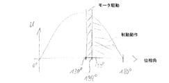
図6は、ユニバーサルモータの制動動作時での電源電圧の1つの半波を電源a,bの電源電圧の位相角について示す。本発明の基本思想は、電源電圧を用いてユニバーサルモータを穏やかに制動することである。ここではまず制動動作の際に短時間のモータ動作が実行され、続いて制動動作に切り替えられる。図示の実施例では、位相角が130゜のときに第1のスイッチ1が導通状態に切り換えられ、第2のスイッチ1’はまだ遮断されている。続いて位相角が134°のときに第2のスイッチ1’も導通状態に切り換えられ、これによりユニバーサルモータに実際の制動作用が及ぼされる。位相角が130°から134°の間の時間では、短時間のモータ動作が実行される。位相角134°の後では、純粋な制動動作が実行され、これはたとえば180°の位相角で終了する。
FIG. 6 shows one half wave of the power supply voltage during the braking operation of the universal motor with respect to the phase angle of the power supply voltage of the power supplies a and b. The basic idea of the present invention is to gently brake the universal motor using the power supply voltage. Here are brief motor operation executed when the first braking operation, is switched to subsequently braking operation. In the illustrated embodiment, the phase angle is 130 ° the
選択された実施形態に応じて、スイッチオン角、すなわち制動過程時の第1のスイッチの導通状態への切り換えのためのスイッチオン時点は、種々のパラメータ、たとえばユニバーサルモータの回転数、ユニバーサルモータの温度、所望の制動時間および/または集電子のブラシの所望の保護に依存して変えられる。さらにモータ動作を短時間調整するための第1のスイッチの切り換えと、制動動作を調整するための第2のスイッチの切り換えとの間の遅延時間も変えられる。 Depending on the selected embodiment, the switch-on angle, i.e. the switch-on time for the switch to the conductive state of the first switch during braking process, various parameters, for example the universal motor speed, the universal motor temperature, change depending on the desired protection of the desired braking time and / or the current collector of brush Erareru. Furthermore the switching of the first switch for adjusting between Mijikatoki motor operation, Ru delay time is also variable Erare between the switching of the second switch for adjusting the braking action.
第1のスイッチの切り換えと第2のスイッチの切り換えとの間の遅延時間は、たとえばマイクロセカンドからミリセカンドの範囲である。たとえば遅延時間は、1μsから5msの間、または5μsから20msの間、または20μsから50μsの間、または50μsから100μsの間とすることができる。さらに遅延時間は、100μsから300μsの間でも良い。実現形態に依存して、より短い時間またはより長い時間を遅延時間として使用することできる。 Delay time between the switching and the switching of the second switch of the first switch, for example in the range of milliseconds from microseconds. For example the delay time can be between 1μs of 5ms or from 5 .mu.s, for 20ms or between the 50 mu s 20 .mu.s or be between 100 mu s from the 50 [mu] s,,. Further delay time may be between 100μs from 300 μ s. Depending on the implementation, a shorter or longer time may be used as the delay time.
簡単な実施形態では、短時間にモータ動作を開始し、続いて制動動作を開始するための第1のスイッチの作動と第2のスイッチの作動との間の遅延時間は、全制動過程の間、一定とすることができる。 In a simple embodiment, the delay time between the activation of the first switch and the activation of the second switch for starting the motor operation in a short time and subsequently starting the braking operation is the same during the entire braking process. , Can be constant.
別の実施形態では、短時間のモータ動作における第1のスイッチの切り換えと、制動過程において制動動作を開始するための第2のスイッチの切り換えとの間の遅延時間は、たとえば、ユニバーサルモータのパラメータ、たとえば温度、回転数、電気特性(抵抗RおよびインダクタンスLなど)および電源電圧に依存する。 In another embodiment, the switching of the first switch in the motor operation of the short time, the delay time between the switching of the second switch for starting the braking operation in the braking process, for example, of the universal motor parameters For example, it depends on temperature, rotational speed, electrical characteristics ( such as resistance R and inductance L ), and power supply voltage .
たとえば遅延時間は、第1のスイッチの切り換え時点での電源電圧および/またはユニバーサルモータの回転数および/またはユニバーサルモータの温度に依存する。そのために好ましくは実験で求められたテーブルまたは特性曲線がデータメモリに保存されており、これに制御電子回路がアクセスする。 For example, the delay time depends on the power supply voltage at the time of switching the first switch and / or the number of revolutions of the universal motor and / or the temperature of the universal motor . For this purpose, preferably a table or characteristic curve determined experimentally is stored in the data memory, which is accessed by the control electronics.
ユニバーサルモータの温度およびユニバーサルモータの回転数は、対応するセンサ35によって検出することができる。またはたとえば電流および電圧のような動作パラメータを用いて推定または計算することができる。
The temperature of the universal motor and the number of rotations of the universal motor can be detected by the corresponding
選択される実施形態に応じて、電源電圧の各半波の間、図6に基づき説明したように、ユニバーサルモータについて短時間のモータ動作の後に制動動作が実施されてよい。この際、選択された実施形態に応じて、モータ動作は実際の制動動作の前に、たとえば半波の一部においてのみ実施されてもよい。 Depending on the selected Ru embodiment, during each half-wave of the supply voltage, as described with reference to FIG. 6, a braking operation after a short time of motor operation for universal motor may be implemented. In this case, depending on the selected embodiment, the motor operation may be carried out, for example , only in part of the half-wave, before the actual braking operation.
制御電子回路は、対応するソフトウエアプログラムを備えるコントローラの形に構成されており、第1と第2のスイッチの作動を実施する。そのためにさらにメモリが設けられており、このメモリには制御プログラムと制御データ、たとえばスイッチの位相制御角、すなわち、図6の制動動作にしたがい第1のスイッチと第2のスイッチをスイッチオンおよびスイッチオフするための位相角が保存されている。とりわけメモリには、第1および/または第2のスイッチがスイッチオン乃至スイッチオフされる位相角に関するテーブルおよび/または特性曲線が保存されている。ここで、テーブルおよび特性曲線は、たとえば、ユニバーサルモータおよび/または電源電圧のパラメータに依存する。とりわけ、制動動作中の第1のスイッチの後の第2のスイッチの作動のための遅延時間は、第1のスイッチの切り換え時点での電源電圧および/またはユニバーサルモータの回転数および/もしくはユニバーサルモータの温度に依存する。そのために、たとえば実験的に求められたテーブルおよび/または特性曲線が保存されている。 The control electronics are arranged in the form of a controller with a corresponding software program and perform the operation of the first and second switches. For this purpose, a further memory is provided, in which the control program and control data, for example the phase control angle of the switch , ie the first switch and the second switch are switched on and switched according to the braking operation of FIG. The phase angle for turning off is stored . Especially in the memory, the table and / or characteristic curves regarding the phase angle first and / or second switch is switched on or switched off are stored. Here, the table and the characteristic curve depend, for example, on the parameters of the universal motor and / or the supply voltage . In particular, the delay time for the operation of the second switch after the first switch during braking operation is dependent on the supply voltage and / or the rotational speed of the universal motor and / or the universal motor at the time of switching of the first switch. Depends on the temperature. For this purpose, for example, tables and / or characteristic curves determined experimentally are stored .
さらに、半波ごとの位相制御角の変化を設定するデータが記憶されてもよい。たとえば、第1のスイッチの導通状態への切替えおよび/または第2のスイッチの導通状態への切替えのための1つの半波から次の半波までの位相角の変化は、たとえばパーセントの最高値に制限することができる。 Moreover, data for setting the change in the phase control angle of each half wave may be stored. For example, the change in the phase angle from one half wave to the next half wave for switching the conducting state of the first switch and / or switching the conducting state of the second switch to , for example, the highest value of the percentage Can be limited to.
図3〜5から、制動動作の終了時には電圧極性の異なる半波の波束が順次連続することが分かる。したがって設定された時間または設定された数の半波に対して、モータ動作と制動動作を伴う制動を実施するために、たとえば電源電圧の正の半波だけが使用される。続いて、短時間のモータ動作と引き続く制動動作を伴うユニバーサルモータの制動を実施するために、図6に基づき説明したように、電源電圧の負の半波の波束が使用される。 3 to 5, it can be seen that half-wave wave packets with different voltage polarities successively follow at the end of the braking operation. Thus, for a set time or set number of half-wave, for carrying out the braking with the braking operation and the motor operation, for example, only the positive half-wave of the supply voltage is Ru is used. Then, to implement the braking of universal motors with subsequent braking operation and short time of the motor operation, as described with reference to FIG. 6, the negative half-wave wave packet of supply voltage is used.
Claims (14)
制動動作中に前記ユニバーサルモータの界磁巻線(3)に第1と第2のスイッチ(1、1’)を介して電源から給電され、前記ユニバーサルモータの電機子(2)は前記第2のスイッチ(1’)を介して短絡され、
モータ動作は前記第1のスイッチ(1)を介して行われ、
制御電子回路(5)が設けられており、該制御電子回路は、制動動作中に電源電圧の各半波内で短時間だけモータ動作が行われ、その後再び制動動作が行われるように構成されており、但し、前記第1のスイッチ(1)がまず導通状態に切り換えられてモータ動作が開始され、所定の遅延時間を以て前記第2のスイッチ(1’)が導通状態に切り換えられて制動動作が開始される、
電気力学的制動装置。 An electrodynamic braking device for a universal motor comprising a device for switching from motor operation to braking operation,
During the braking operation, the field winding (3) of the universal motor is fed from the power source via the first and second switches (1, 1 '), and the armature (2) of the universal motor is is short-circuited via the switch (1 '),
Motor operation is performed via the first switch (1),
A control electronic circuit (5) is provided, which is configured such that during the braking operation, the motor operation is performed for a short time within each half wave of the power supply voltage and then the braking operation is performed again. and, provided that the first switch (1) is presented first we switched to the conductive state motor operation is started, the second switch with a predetermined delay time (1 ') is being found switched to a conductive state Braking operation is started,
Electrodynamic braking device.
前記第2のスイッチ(1’)には、識別接点(f)を備える切換素子(S)が前置接続されている、
ことを特徴とする請求項1から9までのいずれか一項に記載の電気力学的制動装置。 During the braking operation, the second switch (1 ′) is connected in parallel to the armature (2), connected in series with the field winding (3) and the first switch (1),
A switching element (S) having an identification contact (f) is connected in front to the second switch (1 ′).
An electrodynamic braking device according to any one of claims 1 to 9, characterized in that
制動動作中に前記ユニバーサルモータの界磁巻線(3)に第1と第2のスイッチ(1、1’)を介して電源電圧から給電され、前記ユニバーサルモータの電機子(2)が前記第2のスイッチ(1’)を介して短絡され、
制動動作中に電源電圧の各半波内で短時間、前記ユニバーサルモータのモータ動作が前記第1のスイッチの導通状態への切り替えによって行われ、
後続の制動動作が前記第2のスイッチ(1’)の導通状態への切替えによって所定の遅延時間を以て行われる、
制動方法。 A method of braking a universal motor comprising a device for switching the universal motor from motor operation to braking operation,
During the braking operation, the field winding (3) of the universal motor is fed from the power supply voltage via the first and second switches (1, 1 '), and the armature (2) of the universal motor is Short-circuited through the two switches (1 '),
A short time in each half-wave of the supply voltage during braking operation, the motor operation of the universal motor is performed by switching to the conductive state of the first switch,
The subsequent braking operation is performed with a predetermined delay time by switching the second switch (1 ′) to the conductive state .
Braking method.
Applications Claiming Priority (5)
| Application Number | Priority Date | Filing Date | Title |
|---|---|---|---|
| DE200910060139 DE102009060139A1 (en) | 2009-12-23 | 2009-12-23 | Electro-dynamic braking device for universal motor, has winding fed over triacs during brake operation, where motor operation during brake operation is sufficient for commutation at motor collector and is not sufficient to drive armature |
| DE102009060139.2 | 2009-12-23 | ||
| DE102010004311A DE102010004311A1 (en) | 2010-01-11 | 2010-01-11 | Electrodynamic braking device for universal motor, has control electronic unit simulating brake operation and motor operation, switch conductively switched, and other switch conductively switched with predetermined time delay |
| DE102010004311.7 | 2010-01-11 | ||
| PCT/EP2010/070457 WO2011076827A2 (en) | 2009-12-23 | 2010-12-22 | Braking device for a universal motor |
Publications (3)
| Publication Number | Publication Date |
|---|---|
| JP2013516152A JP2013516152A (en) | 2013-05-09 |
| JP2013516152A5 JP2013516152A5 (en) | 2014-06-19 |
| JP5645967B2 true JP5645967B2 (en) | 2014-12-24 |
Family
ID=44064659
Family Applications (1)
| Application Number | Title | Priority Date | Filing Date |
|---|---|---|---|
| JP2012545314A Active JP5645967B2 (en) | 2009-12-23 | 2010-12-22 | Braking device for universal motor |
Country Status (6)
| Country | Link |
|---|---|
| US (1) | US9590538B2 (en) |
| EP (1) | EP2517349B1 (en) |
| JP (1) | JP5645967B2 (en) |
| CN (1) | CN102742146B (en) |
| RU (1) | RU2553674C2 (en) |
| WO (1) | WO2011076827A2 (en) |
Families Citing this family (10)
| Publication number | Priority date | Publication date | Assignee | Title |
|---|---|---|---|---|
| DE102012205728A1 (en) | 2012-04-05 | 2013-10-10 | Robert Bosch Gmbh | Method and device for the electrodynamic braking of a universal motor |
| DE102012205876A1 (en) | 2012-04-11 | 2013-10-17 | Robert Bosch Gmbh | Method and device for the electrodynamic braking of a universal motor |
| US9218075B2 (en) | 2012-11-01 | 2015-12-22 | Immersion Corporation | Haptically-enabled system with braking |
| EP2947765B1 (en) | 2014-05-20 | 2020-08-26 | Black & Decker Inc. | Electronic braking for a universal motor in a power tool |
| CN107530795B (en) * | 2014-11-24 | 2020-10-23 | 罗伯特·博世有限公司 | Motor braking system and method for power tool |
| CN104617823A (en) * | 2015-01-12 | 2015-05-13 | 金懋实业有限公司 | Damp control circuit of motor magnetic loop and control method of damp control circuit |
| US11047528B2 (en) | 2016-02-12 | 2021-06-29 | Black & Decker Inc. | Electronic braking for a power tool having a brushless motor |
| CN107294466A (en) * | 2016-04-05 | 2017-10-24 | 德昌电机(深圳)有限公司 | Electric tool and its motor driven systems |
| CN109120187B (en) * | 2018-06-05 | 2021-04-27 | 东南大学 | Controller of electromagnetic braking device |
| CN109450298A (en) * | 2018-11-29 | 2019-03-08 | 惠州拓邦电气技术有限公司 | A kind of electric brake circuit, electric appliance and method |
Family Cites Families (17)
| Publication number | Priority date | Publication date | Assignee | Title |
|---|---|---|---|---|
| NL7109226A (en) * | 1971-07-03 | 1973-01-05 | ||
| SU544573A1 (en) * | 1975-11-04 | 1977-01-30 | Предприятие П/Я Г-4868 | Device for electrodynamic braking of a traction motor |
| JPS5992785A (en) * | 1982-11-16 | 1984-05-29 | Fuji Electric Co Ltd | Brake device for motor |
| SU1707726A1 (en) * | 1989-12-05 | 1992-01-23 | Харьковский Институт Инженеров Железнодорожного Транспорта Им.С.М.Кирова | Direct current drive |
| RU2007835C1 (en) * | 1992-02-17 | 1994-02-15 | Московский Институт Инженеров Железнодорожного Транспорта | Electric drive for hand tool |
| IT1258950B (en) | 1992-06-05 | 1996-03-11 | Black & Decker Inc | CONTROLLED BRAKING DEVICE FOR ELECTRIC MOTORS, IN PARTICULAR OF PORTABLE TOOLS |
| DE4333064A1 (en) * | 1993-09-29 | 1995-03-30 | Scintilla Ag | Brake circuit for a universal motor |
| AU4334699A (en) * | 1998-06-05 | 1999-12-20 | Milwaukee Electric Tool Corporation | Braking and control circuit for electric power tools |
| DE19843106B4 (en) * | 1998-09-21 | 2005-08-18 | Ebm-Papst Mulfingen Gmbh & Co. Kg | System for controlling the speed of AC motors |
| DE19932742C1 (en) | 1999-01-07 | 2000-09-21 | Hans Hermann Rottmerhusen | Network brake device for an electric hand tool |
| RU2168259C1 (en) * | 2000-02-14 | 2001-05-27 | Зао "Кросна-Электра" | Direct-current drive |
| JP2002153087A (en) * | 2000-11-13 | 2002-05-24 | Max Co Ltd | Ac motor drive circuit |
| DE10234397A1 (en) | 2002-07-23 | 2004-01-29 | C. & E. Fein Gmbh & Co Kg | Braked series motor and method for braking a series motor |
| DE10317636A1 (en) | 2003-04-17 | 2004-11-25 | Robert Bosch Gmbh | Braking device for an electric motor |
| US8280569B2 (en) * | 2004-12-09 | 2012-10-02 | General Electric Company | Methods and systems for improved throttle control and coupling control for locomotive and associated train |
| ES1065745Y (en) * | 2007-06-21 | 2008-01-16 | Coprecitec Sl | WASHER CONTROL DEVICE |
| CN102484447B (en) * | 2009-03-03 | 2015-05-06 | 罗伯特·博世有限公司 | Electrodynamic braking device for universal motor |
-
2010
- 2010-12-22 US US13/518,799 patent/US9590538B2/en active Active
- 2010-12-22 EP EP10796054.4A patent/EP2517349B1/en active Active
- 2010-12-22 CN CN201080063277.9A patent/CN102742146B/en active Active
- 2010-12-22 WO PCT/EP2010/070457 patent/WO2011076827A2/en active Application Filing
- 2010-12-22 RU RU2012131272/07A patent/RU2553674C2/en not_active IP Right Cessation
- 2010-12-22 JP JP2012545314A patent/JP5645967B2/en active Active
Also Published As
| Publication number | Publication date |
|---|---|
| EP2517349B1 (en) | 2014-03-26 |
| US20120319627A1 (en) | 2012-12-20 |
| WO2011076827A3 (en) | 2012-08-16 |
| CN102742146B (en) | 2015-12-09 |
| JP2013516152A (en) | 2013-05-09 |
| US9590538B2 (en) | 2017-03-07 |
| WO2011076827A2 (en) | 2011-06-30 |
| WO2011076827A9 (en) | 2011-10-20 |
| CN102742146A (en) | 2012-10-17 |
| RU2012131272A (en) | 2014-01-27 |
| EP2517349A2 (en) | 2012-10-31 |
| RU2553674C2 (en) | 2015-06-20 |
Similar Documents
| Publication | Publication Date | Title |
|---|---|---|
| JP5645967B2 (en) | Braking device for universal motor | |
| JP2013516152A5 (en) | ||
| US8541963B2 (en) | Electrodynamic braking device for a universal motor | |
| JPH0638565A (en) | Controlled brake device for electric motor and for portable tool | |
| US9614466B2 (en) | Electronic braking for a universal motor in a power tool | |
| US7071645B2 (en) | Braking device for an electric motor, electrical apparatus provided with the braking device, and a method of braking | |
| CN108602182B (en) | Electric tool | |
| JPH09503376A (en) | Electric motor with electric braking device | |
| RU2008113216A (en) | METHOD FOR REGULATING MECHANICALLY SWITCHED MOTOR | |
| WO2004042912B1 (en) | Motor driver | |
| US6448727B1 (en) | Mains braking device for a line-powered power tool | |
| JP2013188821A (en) | Electric tool | |
| US6680596B1 (en) | Electric motor having regenerative braking | |
| WO2002054565A3 (en) | Method for commutating an electronically commutated dc motor, and motor for carrying out said method | |
| JP2000501920A (en) | Series motor with electric brake | |
| JP6054518B2 (en) | How to control a stepping motor | |
| JP4491895B2 (en) | Capacitor induction motor starter | |
| JP2002283052A (en) | Welding equipment | |
| JP2004237855A (en) | Wiper device | |
| SU773879A1 (en) | Three-phase induction motor braking device | |
| SU1758818A1 (en) | Induction motor control gear | |
| JPS6040271B2 (en) | Capacitor motor rotation direction conversion circuit | |
| JP2004237896A (en) | Wiper device | |
| WO2013060327A1 (en) | A method for operating a mechanically commutated electric motor | |
| JPS6028236B2 (en) | braking device |
Legal Events
| Date | Code | Title | Description |
|---|---|---|---|
| A131 | Notification of reasons for refusal |
Free format text: JAPANESE INTERMEDIATE CODE: A131 Effective date: 20131007 |
|
| A601 | Written request for extension of time |
Free format text: JAPANESE INTERMEDIATE CODE: A601 Effective date: 20131227 |
|
| A602 | Written permission of extension of time |
Free format text: JAPANESE INTERMEDIATE CODE: A602 Effective date: 20140110 |
|
| A524 | Written submission of copy of amendment under article 19 pct |
Free format text: JAPANESE INTERMEDIATE CODE: A524 Effective date: 20140401 |
|
| TRDD | Decision of grant or rejection written | ||
| A01 | Written decision to grant a patent or to grant a registration (utility model) |
Free format text: JAPANESE INTERMEDIATE CODE: A01 Effective date: 20141006 |
|
| A61 | First payment of annual fees (during grant procedure) |
Free format text: JAPANESE INTERMEDIATE CODE: A61 Effective date: 20141104 |
|
| R150 | Certificate of patent or registration of utility model |
Ref document number: 5645967 Country of ref document: JP Free format text: JAPANESE INTERMEDIATE CODE: R150 |
|
| R250 | Receipt of annual fees |
Free format text: JAPANESE INTERMEDIATE CODE: R250 |
|
| R250 | Receipt of annual fees |
Free format text: JAPANESE INTERMEDIATE CODE: R250 |
|
| R250 | Receipt of annual fees |
Free format text: JAPANESE INTERMEDIATE CODE: R250 |
|
| R250 | Receipt of annual fees |
Free format text: JAPANESE INTERMEDIATE CODE: R250 |
|
| R250 | Receipt of annual fees |
Free format text: JAPANESE INTERMEDIATE CODE: R250 |
|
| R250 | Receipt of annual fees |
Free format text: JAPANESE INTERMEDIATE CODE: R250 |
|
| R250 | Receipt of annual fees |
Free format text: JAPANESE INTERMEDIATE CODE: R250 |