RU2514786C1 - Analogue selector - Google Patents
Analogue selector Download PDFInfo
- Publication number
- RU2514786C1 RU2514786C1 RU2013104388/08A RU2013104388A RU2514786C1 RU 2514786 C1 RU2514786 C1 RU 2514786C1 RU 2013104388/08 A RU2013104388/08 A RU 2013104388/08A RU 2013104388 A RU2013104388 A RU 2013104388A RU 2514786 C1 RU2514786 C1 RU 2514786C1
- Authority
- RU
- Russia
- Prior art keywords
- sorter
- inputs
- outputs
- elements
- input
- Prior art date
Links
Abstract
Description
Изобретение относится к автоматике и аналоговой вычислительной технике и может быть использовано для построения функциональных узлов аналоговых вычислительных машин, средств автоматического регулирования и управления, аналоговых процессоров и др.The invention relates to automation and analog computing and can be used to build functional units of analog computers, means of automatic regulation and control, analog processors, etc.
Известны аналоговые селекторы (см., например, авт.св. СССР 1322325, кл. G06G 7/25, 1987 г.), которые воспроизводят двойственные операции выделения минимального и максимального из двух входных аналоговых сигналов.Known analog selectors (see, for example, ed. St. USSR 1322325, class G06G 7/25, 1987), which reproduce the dual operations of selecting the minimum and maximum of the two input analog signals.
К причине, препятствующей достижению указанного ниже технического результата при использовании известных аналоговых селекторов, относятся ограниченные функциональные возможности, обусловленные тем, что не допускается обработка четырех аналоговых сигналов.The reason that impedes the achievement of the technical result indicated below when using known analog selectors includes limited functionality, due to the fact that processing of four analog signals is not allowed.
Наиболее близким устройством того же назначения к заявленному изобретению по совокупности признаков является принятый за прототип аналоговый селектор (фиг.2 в описании изобретения к авт.св. СССР 1718237, кл. G06G 7/12, 1992 г.), который содержит сортировщик и воспроизводит двойственные операции выделения минимального и максимального из двух входных аналоговых сигналов.The closest device of the same purpose to the claimed invention according to the totality of features is the analog selector adopted as a prototype (Fig. 2 in the description of the invention to the auth. Of the USSR 1718237, class G06G 7/12, 1992), which contains a sorter and reproduces dual operations of separation of the minimum and maximum of the two input analog signals.
К причине, препятствующей достижению указанного ниже технического результата при использовании прототипа, относятся ограниченные функциональные возможности, обусловленные тем, что не допускается обработка четырех аналоговых сигналов.The reason that impedes the achievement of the technical result indicated below when using the prototype is limited functionality due to the fact that processing of four analog signals is not allowed.
Техническим результатом изобретения является расширение функциональных возможностей за счет обеспечения воспроизведения двойственных операций выделения минимального и максимального либо двойственных операций выделения супраминимального и субмаксимального из четырех входных аналоговых сигналов.The technical result of the invention is the expansion of functionality by ensuring the reproduction of dual operations of selecting the minimum and maximum or dual operations of selecting supraminimum and submaximal from four input analog signals.
Указанный технический результат при осуществлении изобретения достигается тем, что в аналоговом селекторе, содержащем сортировщик, который содержит компаратор, подсоединенный неинвертирующим и инвертирующим входами соответственно к первому и второму входам сортировщика, и 1-й ![]()
![]()
![]()
![]()
На чертеже представлена схема предлагаемого аналогового селектора.The drawing shows a diagram of the proposed analog selector.
Аналоговый селектор содержит сортировщики 11, 12, элементы МАХ 21, 22 и элементы MIN 31, 32. Каждый сортировщик содержит компаратор 4, подключенный неинвертирующим, инвертирующим входами и выходом соответственно к первому, второму входам сортировщика и первому входу элемента ИСКЛЮЧАЮЩЕЕ ИЛИ 5, второй вход и выход которого соединены соответственно с входом управления сортировщика и управляющим входом переключателей 61, 62, причем нормально замкнутый, нормально разомкнутый и коммутационный контакты переключателя 6i ![]()
![]()
![]()
![]()
Работа предлагаемого аналогового селектора осуществляется следующим образом. На его первый,…,четвертый информационные и настроечный входы подаются соответственно подлежащие обработке аналоговые сигналы (напряжения) х1,…,х4 и управляющий сигнал f∈{0,l}. Если на входе управления сортировщика присутствует лог. «0» (лог. «1») и сигнал на его первом входе меньше либо больше сигнала на его втором входе, то нормально замкнутый контакт каждого его переключателя соответственно замкнут (разомкнут) либо разомкнут (замкнут), а нормально разомкнутый контакт соответственно разомкнут (замкнут) либо замкнут (разомкнут). Следовательно, если f=0 (f=1), то на первом и втором выходах каждого сортировщика выделяются соответственно минимальный (максимальный) и максимальный (минимальный) из сигналов, поданных на его первый, второй входы. Таким образом, на первом, втором выходах предлагаемого аналогового селектора имеемThe work of the proposed analog selector is as follows. At its first, ..., fourth information and tuning inputs, the analog signals (voltages) x 1 , ..., x 4 and the control signal f∈ {0, l}, respectively, are to be processed. If there is a log at the control input of the sorter. “0” (log. “1”) and the signal at its first input is less than or greater than the signal at its second input, then the normally closed contact of each of its switches is respectively closed (open) or open (closed), and the normally open contact is respectively open ( closed) or closed (open). Therefore, if f = 0 (f = 1), then at the first and second outputs of each sorter, the minimum (maximum) and maximum (minimum) of the signals applied to its first, second inputs are allocated. Thus, at the first, second outputs of the proposed analog selector, we have

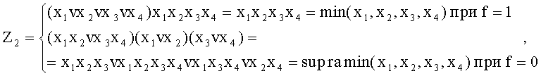
где символами ·, v обозначены операции min, max. То есть, при f=1 либо f=0 воспроизводятся соответственно двойственные операции min(x1, x2, x3, x4) и max(x1, x2, x3, x4) либо двойственные операции supramin(x1, x2, x3, x4) и submax (x1, х2, х3, х4).where the symbols ·, v denote the operations min, max. That is, for f = 1 or f = 0, the dual operations min (x 1 , x 2 , x 3 , x 4 ) and max (x 1 , x 2 , x 3 , x 4 ) or the dual operations supramin (x 1 , x 2 , x 3 , x 4 ) and submax (x 1 , x 2 , x 3 , x 4 ).
Вышеизложенные сведения позволяют сделать вывод, что предлагаемый аналоговый селектор обладает более широкими по сравнению с прототипом функциональными возможностями, поскольку обеспечивает воспроизведение двойственных операций выделения минимального и максимального либо двойственных операций выделения супраминимального и субмаксимального из четырех входных аналоговых сигналов.The above information allows us to conclude that the proposed analog selector has wider functionality compared to the prototype, since it provides the reproduction of dual operations of selecting the minimum and maximum or dual operations of selecting the supraminimum and submaximal from four input analog signals.
Claims (1)
Priority Applications (1)
| Application Number | Priority Date | Filing Date | Title |
|---|---|---|---|
| RU2013104388/08A RU2514786C1 (en) | 2013-02-01 | 2013-02-01 | Analogue selector |
Applications Claiming Priority (1)
| Application Number | Priority Date | Filing Date | Title |
|---|---|---|---|
| RU2013104388/08A RU2514786C1 (en) | 2013-02-01 | 2013-02-01 | Analogue selector |
Publications (1)
| Publication Number | Publication Date |
|---|---|
| RU2514786C1 true RU2514786C1 (en) | 2014-05-10 |
Family
ID=50629493
Family Applications (1)
| Application Number | Title | Priority Date | Filing Date |
|---|---|---|---|
| RU2013104388/08A RU2514786C1 (en) | 2013-02-01 | 2013-02-01 | Analogue selector |
Country Status (1)
| Country | Link |
|---|---|
| RU (1) | RU2514786C1 (en) |
Citations (7)
| Publication number | Priority date | Publication date | Assignee | Title |
|---|---|---|---|---|
| SU1322325A1 (en) * | 1985-06-26 | 1987-07-07 | Предприятие П/Я А-3517 | Minimax amplitude discriminator |
| SU1718237A1 (en) * | 1990-03-05 | 1992-03-07 | Специальное Конструкторское Бюро Вычислительной Техники Института Кибернетики Ан Эстонии | Analog signal separator |
| US5408194A (en) * | 1993-06-25 | 1995-04-18 | Synaptics, Incorporated | Adaptive analog minimum/maximum selector and subtractor circuit |
| US5414310A (en) * | 1993-05-17 | 1995-05-09 | Texas Instruments Incorporated | Analog voltage maximizer and minimizer circuits |
| RU2109338C1 (en) * | 1995-06-06 | 1998-04-20 | Ульяновский государственный технический университет | Analog logic element for identifying and selecting extreme, superextreme, or subextreme values of information signal |
| RU2143739C1 (en) * | 1999-02-16 | 1999-12-27 | Ульяновский государственный технический университет | Logical device for rank processing of analog signals |
| US6188251B1 (en) * | 1998-04-01 | 2001-02-13 | Roland Priemer | Analog voltage maximum selection and sorting circuits |
-
2013
- 2013-02-01 RU RU2013104388/08A patent/RU2514786C1/en not_active IP Right Cessation
Patent Citations (7)
| Publication number | Priority date | Publication date | Assignee | Title |
|---|---|---|---|---|
| SU1322325A1 (en) * | 1985-06-26 | 1987-07-07 | Предприятие П/Я А-3517 | Minimax amplitude discriminator |
| SU1718237A1 (en) * | 1990-03-05 | 1992-03-07 | Специальное Конструкторское Бюро Вычислительной Техники Института Кибернетики Ан Эстонии | Analog signal separator |
| US5414310A (en) * | 1993-05-17 | 1995-05-09 | Texas Instruments Incorporated | Analog voltage maximizer and minimizer circuits |
| US5408194A (en) * | 1993-06-25 | 1995-04-18 | Synaptics, Incorporated | Adaptive analog minimum/maximum selector and subtractor circuit |
| RU2109338C1 (en) * | 1995-06-06 | 1998-04-20 | Ульяновский государственный технический университет | Analog logic element for identifying and selecting extreme, superextreme, or subextreme values of information signal |
| US6188251B1 (en) * | 1998-04-01 | 2001-02-13 | Roland Priemer | Analog voltage maximum selection and sorting circuits |
| RU2143739C1 (en) * | 1999-02-16 | 1999-12-27 | Ульяновский государственный технический университет | Logical device for rank processing of analog signals |
Similar Documents
| Publication | Publication Date | Title |
|---|---|---|
| RU2580801C1 (en) | Majority module | |
| RU2533079C1 (en) | Majority module | |
| US10102090B2 (en) | Non-destructive analysis to determine use history of processor | |
| RU2602382C1 (en) | Ranked filter | |
| RU2700554C1 (en) | Majority module | |
| RU2621281C1 (en) | Logic converter | |
| RU2542895C1 (en) | Logical converter | |
| RU2514786C1 (en) | Analogue selector | |
| RU2641454C2 (en) | Logic converter | |
| RU2649296C1 (en) | Comparator of binary numbers | |
| Plotnikov et al. | Existence and uniqueness theorem for set-valued Volterra integral equations | |
| RU2704735C1 (en) | Threshold module | |
| RU2701464C1 (en) | Logic converter | |
| RU2543307C2 (en) | Rank filter | |
| RU2514784C1 (en) | Analogue logic element | |
| RU2300137C1 (en) | Majority module | |
| RU2710866C1 (en) | Rank filter | |
| RU2702968C1 (en) | Rank filter | |
| RU2549158C1 (en) | Logic converter | |
| RU2621376C1 (en) | Logic module | |
| RU2606311C2 (en) | Selector of binary numbers | |
| RU2491626C1 (en) | Address identifier | |
| RU2490706C1 (en) | Analogue multiplexer | |
| RU2676886C1 (en) | Ranked filter | |
| RU2491625C1 (en) | Relator unit |
Legal Events
| Date | Code | Title | Description |
|---|---|---|---|
| MM4A | The patent is invalid due to non-payment of fees |
Effective date: 20150202 |