RU2506373C2 - Channel of opposite flows of multiflow hydraulic actuator - Google Patents
Channel of opposite flows of multiflow hydraulic actuator Download PDFInfo
- Publication number
- RU2506373C2 RU2506373C2 RU2009129129/03A RU2009129129A RU2506373C2 RU 2506373 C2 RU2506373 C2 RU 2506373C2 RU 2009129129/03 A RU2009129129/03 A RU 2009129129/03A RU 2009129129 A RU2009129129 A RU 2009129129A RU 2506373 C2 RU2506373 C2 RU 2506373C2
- Authority
- RU
- Russia
- Prior art keywords
- cavities
- flow
- pressure
- channel
- hydraulic
- Prior art date
Links
- 239000012530 fluid Substances 0.000 claims description 6
- 230000007246 mechanism Effects 0.000 abstract description 8
- 125000004122 cyclic group Chemical group 0.000 abstract description 2
- 239000007788 liquid Substances 0.000 abstract description 2
- 239000000126 substance Substances 0.000 abstract 1
- 238000010586 diagram Methods 0.000 description 2
- 230000009977 dual effect Effects 0.000 description 1
- 238000009434 installation Methods 0.000 description 1
- 238000011089 mechanical engineering Methods 0.000 description 1
- 230000007935 neutral effect Effects 0.000 description 1
Images


Landscapes
- Fluid-Pressure Circuits (AREA)
Abstract
Description
Изобретение относится к машиностроительной гидравлике, в частности к гидроприводам мобильных машин и гидравлических установок циклического действия с несколькими исполнительными механизмами.The invention relates to mechanical engineering hydraulics, in particular to hydraulic drives of mobile machines and hydraulic installations of cyclic action with several actuators.
Известны гидравлические приводы экскаваторов, кранов и манипуляторов в которых каналы, подводящие рабочую жидкость от напорной магистрали, сообщаются с несколькими напорными полостями, от которых запитываются гидродвигатели исполнительных механизмов при их включении. В зависимости от функций, заложенных в гидроприводе, эти каналы могут быть выполнены по различным вариантам.Hydraulic drives of excavators, cranes and manipulators are known in which the channels supplying the working fluid from the pressure line communicate with several pressure cavities, from which the hydraulic motors of the actuators are powered when they are turned on. Depending on the functions inherent in the hydraulic drive, these channels can be performed in various ways.
Когда требуется одновременный подвод рабочей жидкости к нескольким исполнительным механизмам, то канал выполняется так, чтобы он объединил напорные полости, соответствующие этим механизмам, по параллельной схеме (рис.79а, [1]). Такой вариант канала характерен для гидрораспределителей типа МО фирмы Bosch Rexroth AG, он обеспечивает параллельную схему подключения золотников к напору [2].When a simultaneous supply of working fluid to several actuators is required, the channel is made so that it combines the pressure cavities corresponding to these mechanisms in a parallel circuit (Fig. 79a, [1]). This version of the channel is typical for hydraulic valves of the MO type from Bosch Rexroth AG; it provides a parallel circuit for connecting spools to pressure [2].
Недостатком данного варианта канала, подводящего поток, является то, что он не позволяет осуществить совмещение двух и более рабочих движений с регулированием их скорости, так как жидкость стремится поступать в гидродвигатель рабочего органа с наименьшим внешним сопротивлением.The disadvantage of this version of the channel supplying the flow is that it does not allow the combination of two or more working movements with the regulation of their speed, since the liquid tends to enter the hydraulic motor of the working body with the lowest external resistance.
В случае, когда требуется исключить одновременный подвод рабочей жидкости более чем к одному механизму, применяется другой вариант канала. Этот канал формируется из нескольких соединенных последовательно двойных проточных полостей, сообщающихся друг с другом.In the case when it is required to exclude the simultaneous supply of the working fluid to more than one mechanism, another channel option is used. This channel is formed from several double flow cavities connected in series, communicating with each other.
Такой вариант канала обеспечивает индивидуальную схему подключения исполнительных механизмов. Причем, приоритет подключения к напору, при одновременном включении нескольких механизмов, будет у механизма, напорная полость которого запитывается от проточной полости, расположенной ближе всех к началу канала. Рабочая жидкость будет поступать в соответствующую ей напорную полость. При включении этого исполнительного механизма проход между полостями двойной проточной полости будет перекрыт, поэтому, подвода рабочей жидкости к механизмам, запитываемым от следующих двойных проточных полостей не будет (рис.79в, [1]).This channel option provides an individual connection scheme for actuators. Moreover, the priority of connecting to the pressure, with the simultaneous inclusion of several mechanisms, will be for the mechanism, the pressure cavity of which is fed from the flow cavity located closest to the beginning of the channel. The working fluid will flow into its corresponding pressure cavity. When this actuator is turned on, the passage between the cavities of the double flowing cavity will be blocked, therefore, there will be no supply of working fluid to the mechanisms powered by the following double flowing cavities (Fig. 79c, [1]).
Данный вариант подводящего поток канала, обеспечивающий индивидуальную схему подключения исполнительных механизмов к напору, является наиболее близким аналогом заявляемого технического решения и принят за прототип.This version of the feed stream channel, providing an individual circuit for connecting actuators to pressure, is the closest analogue of the claimed technical solution and is taken as a prototype.
Данное изобретение решает следующие задачи:This invention solves the following problems:
а) подача при помощи одного канала двух независимых потоков в напорную полость, соответствующую любому включенному золотнику;a) the supply through one channel of two independent flows into the pressure cavity corresponding to any included spool;
б) подача при помощи одного канала двух независимых друг от друга потоков в раздельные напорные полости двух приоритетных золотников при включении нескольких золотников.b) the supply through one channel of two independent from each other flows into separate pressure cavities of two priority spools when several spools are turned on.
в) упрощение конструкции гидропривода машин.c) simplification of the design of hydraulic machines.
Указанный технический результат достигается тем, что в один подводящий канал с разных его концов подаются два независимых потока, направленных навстречу друг другу. Для обеспечения функции сложения потоков при включении одного исполнительного механизма, а также для обеспечения одновременной работы исполнительных механизмов каждого от своего потока, все проточные полости такого канала соединяют через входы обратных клапанов с соответствующими им напорными полостями.The specified technical result is achieved by the fact that two independent streams directed towards each other are fed into one supply channel from its different ends. To ensure the function of adding flows when one actuator is turned on, as well as to ensure the simultaneous operation of the actuators of each of its own flows, all flow cavities of such a channel are connected through the inlet of the check valves to the corresponding pressure cavities.
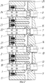
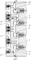
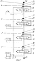
На фиг.1 показан вариант канала, идентичный принятому за прототип. На фиг.2 изображен канал встречных потоков, являющийся предметом данного изобретения. На обеих фигурах показаны каналы, в которых проточные полости запираются при помощи цилиндрического золотника, причем, на этих фигурах и на следующих показаны полости, которые образуют канал встречных потоков. Прочие полости, не относящиеся к каналу встречных потоков, условно не показаны. На фиг.3 приведена схема гидравлическая канала встречных потоков. На фиг.4 стрелками показано направление движения потоков при запирании второй снизу проточной полости. На фиг.5 - то же самое, при запирании первой и третьей проточной полости. На фиг.6 показан вариант канала встречных потоков с разъединяющим элементом, выполненным в виде управляемого клапана и направление движения потоков при запирании второй проточной полости. На фиг.7 - направление движения потоков при запирании первой и третьей проточных полостей канала встречных потоков с клапанным разъединяющим элементом. На фиг.8 приведена упрощенная схема гидропривода с индивидуальной схемой подключения механизмов к двум независимым потокам при помощи одного канала встречных потоков. Для наглядности элементы канала встречных потоков на фиг.8 изображены утолщенными линиями.Figure 1 shows a variant of the channel, identical to that adopted for the prototype. Figure 2 shows the channel of oncoming flows, which is the subject of this invention. In both figures, channels are shown in which the flow cavities are locked by means of a cylindrical spool, and in these figures and in the following, cavities are shown which form a channel of oncoming flows. Other cavities not related to the oncoming flow channel are conventionally not shown. Figure 3 shows a diagram of a hydraulic channel of oncoming flows. In Fig. 4, the arrows show the direction of flow when locking the second flow chamber from the bottom. Figure 5 is the same when locking the first and third flow cavity. Figure 6 shows a variant of the oncoming flow channel with a disconnecting element made in the form of a controlled valve and the direction of flow when locking the second flow cavity. In Fig.7 - the direction of movement of the flows when locking the first and third flow cavities of the channel of the oncoming flows with a valve isolating element. On Fig shows a simplified diagram of a hydraulic actuator with an individual circuit for connecting mechanisms to two independent flows using one channel of oncoming flows. For clarity, the channel elements of the oncoming flows in Fig. 8 are shown by thickened lines.
Канал встречных потоков включает в себя напорные полости 1-4, двойные проточные полости 5-8, с входами 9-12 и выходами 13-16, обратные клапаны 17-24, вход 25 для второго потока. Входы 9-12 и выходы 13-16 соединяются через обратные клапаны 17-24 с напорными полостями 1-4.The oncoming flow channel includes pressure cavities 1-4, dual flow cavities 5-8, with inputs 9-12 and outputs 13-16, check valves 17-24,
В случае выполнения канала встречных потоков по п.2, все перечисленные элементы выполняются в корпусе 26 многопоточного гидравлического распределителя (фиг.2, 6).In the case of execution of the oncoming flow channel according to
Канал встречных потоков работает следующим образом. В нейтральном положении все двойные проточные полости 5-8 не заперты, канал открыт по всей длине от входа 9 до второго входа 25 (фиг.2, 3, 8), давление в канале минимально, обратные клапаны 17-24 закрыты, напорные полости 1-4 отключены от исполнительных механизмов.The counter stream channel works as follows. In the neutral position, all double flow cavities 5-8 are not locked, the channel is open along the entire length from the
При включении только одного исполнительного механизма, происходит перекрытие канала встречных потоков, например, в двойной проточной полости 6. Вход 10 и выход 14 этой полости разъединяются. Поток Р1 от входа 9, минуя открытую двойную проточную полость 5, через обратный клапан 19 направляется в напорную полость 2. Второй поток Р2 от входа 25, минуя открытые двойные проточные полости 8 и 7, через обратный клапан 20, направляется тоже в напорную полость 2. В результате, к исполнительному механизму направляется суммарный расход двух потоков, что позволяет увеличить максимально возможную скорость движения этого исполнительного механизма (фиг.4, 6).When only one actuator is turned on, the channel of oncoming flows overlaps, for example, in a double flowing
Если попытаться подключить еще несколько исполнительных механизмов, например, дополнительно перекрыть двойные проточные полости 5 и 7 (фиг.5, 7), то напорный поток Р1 от входа 9 через обратный клапан 17 будет направлен в напорную полость 1, а оттуда к соответствующему ей исполнительному механизму. Проход потока Р1 к напорной полости 6, перекроет запертая двойная проточная полость 5, расположенная ближе к входу 9 потока Р1.If you try to connect several more actuators, for example, additionally block the
Второй напорный поток Р2 направится от входа 25, минуя открытую проточную полость 8, через обратный клапан 22, в напорную полость 3, а затем к соответствующему ей исполнительному механизму. Проход потока Р2 к напорной полости 2 перекроет запертая двойная проточная полость 7, расположенная ближе к входу 25 потока Р2. В результате, движение исполнительного механизма соответствующего напорной полости 2 станет невозможным.The second pressure stream P2 will go from the
Исполнительный механизм, соответствующий напорной полости 1 будет подключен к напору Р1, а исполнительный механизм, соответствующий напорной полости 3, будет подключен к напору Р2. Таким образом, будет реализована независимая одновременная работа двух исполнительных органов, имеющих приоритет по отношению к ранее включенному исполнительному органу.The actuator corresponding to the
Claims (2)
Priority Applications (1)
| Application Number | Priority Date | Filing Date | Title |
|---|---|---|---|
| RU2009129129/03A RU2506373C2 (en) | 2009-07-28 | 2009-07-28 | Channel of opposite flows of multiflow hydraulic actuator |
Applications Claiming Priority (1)
| Application Number | Priority Date | Filing Date | Title |
|---|---|---|---|
| RU2009129129/03A RU2506373C2 (en) | 2009-07-28 | 2009-07-28 | Channel of opposite flows of multiflow hydraulic actuator |
Publications (2)
| Publication Number | Publication Date |
|---|---|
| RU2009129129A RU2009129129A (en) | 2010-01-20 |
| RU2506373C2 true RU2506373C2 (en) | 2014-02-10 |
Family
ID=42120460
Family Applications (1)
| Application Number | Title | Priority Date | Filing Date |
|---|---|---|---|
| RU2009129129/03A RU2506373C2 (en) | 2009-07-28 | 2009-07-28 | Channel of opposite flows of multiflow hydraulic actuator |
Country Status (1)
| Country | Link |
|---|---|
| RU (1) | RU2506373C2 (en) |
Citations (6)
| Publication number | Priority date | Publication date | Assignee | Title |
|---|---|---|---|---|
| US3800669A (en) * | 1971-08-04 | 1974-04-02 | Rexroth Gmbh G L | Control valve arrangement for a hydraulic drive |
| SU713971A1 (en) * | 1978-08-15 | 1980-02-05 | Производственное Объединение "Красный Экскаватор" | Single-bucket excavator twin-circuit hydraulic drive |
| RU1798444C (en) * | 1989-11-04 | 1993-02-28 | Производственное Объединение "Красный Экскаватор" Им.60-Летия Ссср | Hydraulic drive of single-bucket excavation loader |
| RU2081254C1 (en) * | 1994-10-20 | 1997-06-10 | Акционерное общество по производству экскаваторов | Two-flow hydraulic drive of excavator |
| RU2232235C2 (en) * | 2002-09-26 | 2004-07-10 | Открытое акционерное общество "ВЭКС" | Single-bucket excavator two-flow hydraulic drive |
| US7228781B2 (en) * | 2002-05-24 | 2007-06-12 | Metso Lindemann Gmbh | Hydraulic control in a hydraulic system, especially for the operation of scrap cutters |
-
2009
- 2009-07-28 RU RU2009129129/03A patent/RU2506373C2/en not_active IP Right Cessation
Patent Citations (6)
| Publication number | Priority date | Publication date | Assignee | Title |
|---|---|---|---|---|
| US3800669A (en) * | 1971-08-04 | 1974-04-02 | Rexroth Gmbh G L | Control valve arrangement for a hydraulic drive |
| SU713971A1 (en) * | 1978-08-15 | 1980-02-05 | Производственное Объединение "Красный Экскаватор" | Single-bucket excavator twin-circuit hydraulic drive |
| RU1798444C (en) * | 1989-11-04 | 1993-02-28 | Производственное Объединение "Красный Экскаватор" Им.60-Летия Ссср | Hydraulic drive of single-bucket excavation loader |
| RU2081254C1 (en) * | 1994-10-20 | 1997-06-10 | Акционерное общество по производству экскаваторов | Two-flow hydraulic drive of excavator |
| US7228781B2 (en) * | 2002-05-24 | 2007-06-12 | Metso Lindemann Gmbh | Hydraulic control in a hydraulic system, especially for the operation of scrap cutters |
| RU2232235C2 (en) * | 2002-09-26 | 2004-07-10 | Открытое акционерное общество "ВЭКС" | Single-bucket excavator two-flow hydraulic drive |
Non-Patent Citations (1)
| Title |
|---|
| БЕРКМАН И.Л. и др. Одноковшовые гидравлические экскаваторы. - М.: изд. "Высшая школа", 1973, с.156-158, рис.112. * |
Also Published As
| Publication number | Publication date |
|---|---|
| RU2009129129A (en) | 2010-01-20 |
Similar Documents
| Publication | Publication Date | Title |
|---|---|---|
| CN107850056B (en) | Radial piston pump assembly and its application in hydraulic circuit | |
| CN105190052A (en) | Hydraulic system for construction machine | |
| CN106574640A (en) | Operating table hydraulic drive system | |
| US10323658B2 (en) | Hydraulic drive system for operation table | |
| CN106885014B (en) | Reversal valve and hydraulic system | |
| US11186967B2 (en) | Hydraulic systems for construction machinery | |
| CN110005649B (en) | Load-sensitive adjustable hydraulic system of drilling machine and drilling machine | |
| US10550547B2 (en) | Hydraulic systems for construction machinery | |
| US20130319561A1 (en) | Hydraulic Control Block And Hydraulic System | |
| CN107044551B (en) | Diverter Valves and Hydraulics | |
| JP7748289B2 (en) | Fluid Control Device | |
| US10233614B2 (en) | Fluid pressure control device | |
| CN112833061B (en) | Control valve assembly for engineering machinery and engineering machinery having the same | |
| CN102900718A (en) | Changeover valve device for hydraulic system and hydraulic system for crawler crane | |
| RU2506373C2 (en) | Channel of opposite flows of multiflow hydraulic actuator | |
| CN105673888B (en) | Rotation oil distributing valve for novel combined digital servo actuator | |
| CN116771741A (en) | Hydraulic system | |
| CN107387473B (en) | Tandem channel-borrowing type multipath hydraulic control device | |
| JP6200634B2 (en) | Hydraulic control valve | |
| US9273664B2 (en) | Hydraulic control valve for a one-sided operating differential cylinder having five control edges | |
| KR20200109242A (en) | Control valve, and hydraulic system for construction machine | |
| JP7432382B2 (en) | fluid pressure system | |
| RU2728667C2 (en) | Working fluid supply rate control system | |
| US20180087541A1 (en) | Fast switching 3/2 direct operated hydraulic directional control valve | |
| RU2413819C2 (en) | Hydraulic system of independent flows distribution |
Legal Events
| Date | Code | Title | Description |
|---|---|---|---|
| MM4A | The patent is invalid due to non-payment of fees |
Effective date: 20160729 |