RU2503595C2 - Device for manufacturing and filling containers - Google Patents
Device for manufacturing and filling containers Download PDFInfo
- Publication number
- RU2503595C2 RU2503595C2 RU2010153051/13A RU2010153051A RU2503595C2 RU 2503595 C2 RU2503595 C2 RU 2503595C2 RU 2010153051/13 A RU2010153051/13 A RU 2010153051/13A RU 2010153051 A RU2010153051 A RU 2010153051A RU 2503595 C2 RU2503595 C2 RU 2503595C2
- Authority
- RU
- Russia
- Prior art keywords
- filling
- functional
- rod
- cavity
- nozzle
- Prior art date
Links
- 238000011049 filling Methods 0.000 title claims abstract description 77
- 238000004519 manufacturing process Methods 0.000 title claims abstract description 18
- 238000001125 extrusion Methods 0.000 claims abstract description 31
- 238000004140 cleaning Methods 0.000 claims abstract description 21
- 238000001035 drying Methods 0.000 claims abstract description 16
- 238000004659 sterilization and disinfection Methods 0.000 claims abstract description 16
- 239000000463 material Substances 0.000 claims abstract description 15
- 239000000945 filler Substances 0.000 claims abstract description 11
- 238000004891 communication Methods 0.000 claims abstract description 7
- 229920002994 synthetic fiber Polymers 0.000 claims abstract description 4
- 238000005266 casting Methods 0.000 claims description 37
- 230000001954 sterilising effect Effects 0.000 claims description 21
- 238000001816 cooling Methods 0.000 claims description 9
- 238000007789 sealing Methods 0.000 claims description 4
- 230000015572 biosynthetic process Effects 0.000 claims description 2
- 230000000694 effects Effects 0.000 abstract description 2
- 238000006073 displacement reaction Methods 0.000 abstract 1
- 238000004806 packaging method and process Methods 0.000 abstract 1
- 239000000126 substance Substances 0.000 abstract 1
- 238000000034 method Methods 0.000 description 12
- 238000000465 moulding Methods 0.000 description 5
- 238000012859 sterile filling Methods 0.000 description 5
- 238000009434 installation Methods 0.000 description 4
- 125000004122 cyclic group Chemical group 0.000 description 3
- 238000013461 design Methods 0.000 description 3
- 238000005429 filling process Methods 0.000 description 3
- 239000007788 liquid Substances 0.000 description 2
- 244000005700 microbiome Species 0.000 description 2
- 230000035515 penetration Effects 0.000 description 2
- 238000003466 welding Methods 0.000 description 2
- 238000004500 asepsis Methods 0.000 description 1
- 238000009455 aseptic packaging Methods 0.000 description 1
- 238000000071 blow moulding Methods 0.000 description 1
- 150000001875 compounds Chemical class 0.000 description 1
- 238000007599 discharging Methods 0.000 description 1
- 239000012530 fluid Substances 0.000 description 1
- 230000036512 infertility Effects 0.000 description 1
- 230000007246 mechanism Effects 0.000 description 1
- 230000002093 peripheral effect Effects 0.000 description 1
- 239000000825 pharmaceutical preparation Substances 0.000 description 1
- 229940127557 pharmaceutical product Drugs 0.000 description 1
- 238000012545 processing Methods 0.000 description 1
- 230000006641 stabilisation Effects 0.000 description 1
- 238000011105 stabilization Methods 0.000 description 1
- 238000013022 venting Methods 0.000 description 1
Images

Classifications
-
- B—PERFORMING OPERATIONS; TRANSPORTING
- B65—CONVEYING; PACKING; STORING; HANDLING THIN OR FILAMENTARY MATERIAL
- B65B—MACHINES, APPARATUS OR DEVICES FOR, OR METHODS OF, PACKAGING ARTICLES OR MATERIALS; UNPACKING
- B65B9/00—Enclosing successive articles, or quantities of material, e.g. liquids or semiliquids, in flat, folded, or tubular webs of flexible sheet material; Subdividing filled flexible tubes to form packages
- B65B9/10—Enclosing successive articles, or quantities of material, in preformed tubular webs, or in webs formed into tubes around filling nozzles, e.g. extruded tubular webs
- B65B9/24—Enclosing successive articles, or quantities of material, in preformed tubular webs, or in webs formed into tubes around filling nozzles, e.g. extruded tubular webs the tubes being formed in situ by extrusion
Landscapes
- Engineering & Computer Science (AREA)
- Mechanical Engineering (AREA)
- Filling Of Jars Or Cans And Processes For Cleaning And Sealing Jars (AREA)
- Basic Packing Technique (AREA)
- Extrusion Moulding Of Plastics Or The Like (AREA)
- Containers And Plastic Fillers For Packaging (AREA)
Abstract
Description
Область техники, к которой относится изобретениеFIELD OF THE INVENTION
Изобретение относится к устройству для изготовления и заполнения контейнеров, в котором, по меньшей мере, одна трубка из пластифицированного синтетического материала может подаваться экструзией в открытую форму, причем с помощью заливочного устройства, имеющего несколько раздельных функциональных каналов, в соответствующий контейнер посредством предназначенной для формы заливочной штанги может подаваться, по меньшей мере, материал-заполнитель.The invention relates to a device for the manufacture and filling of containers, in which at least one tube of plasticized synthetic material can be extruded into an open mold, and using a filling device having several separate functional channels, into the corresponding container by means of a filling intended for the form the rods may be fed at least a filler material.
Уровень техникиState of the art
Из уровня техники в данной области известна защищенная товарным знаком bottelpack® система, которая обеспечивает экономичное автоматическое формование (формование раздувом или вакуумное формование), заполнение и запечатывание контейнеров. Когда эти контейнеры должны заполняться чувствительным продуктом, таким как фармацевтические продукты, должны соблюдаться международные стандарты на асептическую упаковку.The bottelpack® system protected by the trademark Bottelpack® is known in the art and provides economical automatic molding (blow molding or vacuum molding), filling and sealing of containers. When these containers are to be filled with a sensitive product, such as pharmaceutical products, international aseptic packaging standards must be followed.
Для удовлетворения этих требований известны решения, в которых форма для изготовления контейнера, когда она приводится в положение заполнения, находится в так называемом стерильном пространстве заполнения, в котором стерильный воздух обтекает заливочное отверстие контейнера и создает эффективную защиту от проникновения микроорганизмов до тех пор, пока после завершения процесса заполнения не будут закрыты подвижные части формы, чтобы комбинированным вакуумно-сварочным способом сформовать закрытую головку контейнера. Такие стерильные пространства заполнения и устройства для стерильного заполнения контейнеров известны в уровне техники, например, из патентных документов DE 19648087 A1 или US 5862840.To satisfy these requirements, solutions are known in which the mold for the manufacture of the container, when it is brought into the filling position, is located in the so-called sterile filling space, in which sterile air flows around the filling opening of the container and provides effective protection against the penetration of microorganisms until after the completion of the filling process, the movable parts of the mold will not be closed in order to form a closed container head using the combined vacuum-welding method. Such sterile filling spaces and devices for sterile filling of containers are known in the art, for example, from patent documents DE 19648087 A1 or US 5862840.
Дополнительной мерой для соблюдения стерильности при изготовлении в соответствии с международной классификацией по классу 100 является проводимая периодически, и в каждом случае в начале периода изготовления, тщательная очистка и стерилизация как заливочного устройства с его функциональными каналами, так и взаимодействующих с ним частей.An additional measure to maintain sterility during manufacture in accordance with the international classification according to class 100 is carried out periodically, and in each case at the beginning of the manufacturing period, thorough cleaning and sterilization of both the filling device with its functional channels and the parts interacting with it.
Раскрытие изобретенияDisclosure of invention
Задачей изобретения является создание устройства указанного типа, в котором процессы очистки и стерилизации могут осуществляться особенно просто и более эффективно по сравнению с известными решениями.The objective of the invention is to provide a device of this type, in which the cleaning and sterilization processes can be carried out especially simply and more efficiently compared to known solutions.
В соответствии с изобретением решение поставленной задачи достигается за счет устройства, обладающего совокупностью признаков по пункту 1 формулы изобретения.In accordance with the invention, the solution of the problem is achieved due to the device having the set of features according to
Согласно этому пункту существенная особенность изобретения заключается в том, что в устройстве имеется охватывающая заливочную штангу насадка, которая содержит, по меньшей мере, одну функциональную полость, в своем функциональном положении для целей очистки и/или стерилизации и/или сушки устанавливает проводящее среду сообщение между своей соответствующей полостью и предназначенным для нее функциональным каналом заливочного устройства и во время изготовления и заполнения контейнеров удалена из своего функционального положения.According to this paragraph, an essential feature of the invention lies in the fact that the device has a nozzle covering the filling rod, which contains at least one functional cavity, in its functional position for the purposes of cleaning and / or sterilization and / or drying, establishes a conductive medium between by its corresponding cavity and the functional channel of the filling device intended for it, and removed from its functional position during the manufacture and filling of containers.
Благодаря этому открывается возможность через соответствующий функциональный канал заливочного устройства вводить в функциональную полость или функциональные полости внутри охватывающей насадки текучие среды для очистки, стерилизации, охлаждения/сушки и т.д. Другими словами, охватывающая насадка образует составную часть очистного, стерилизующего и/или сушильного устройства, которая приводится в действие соответствующей подачей среды от заливочного устройства для приведения устройства в целом в асептическое состояние для начала периода изготовления.This opens up the possibility through the corresponding functional channel of the filling device to introduce fluids into the functional cavity or functional cavities inside the nozzle for cleaning, sterilization, cooling / drying, etc. In other words, the female nozzle forms an integral part of the cleaning, sterilizing and / or drying device, which is actuated by a suitable medium supply from the filling device to bring the device as a whole into an aseptic state to begin the manufacturing period.
В конструктивных примерах выполнения устройства с целью рационального производственного процесса, по меньшей мере, одна заливочная штанга выполнена с возможностью установки в выбранные рабочие положения посредством продольного перемещения и при своем рабочем положении взаимодействия с охватывающей насадкой входит своим продольным участком, по меньшей мере, в одну функциональную полость охватывающей насадки, находящейся в функциональном положении. За счет этого предусмотренная для проведения процесса очистки, стерилизации или охлаждения/сушки среда может поступать в соответствующую полость внутри охватывающей насадки непосредственно через функциональные каналы, проходящие внутри заливочной штанги или вдоль нее. Благодаря этому не только осуществляется очистка, стерилизация и сушка функциональных каналов системы проходящими по ним средами, но соответствующие среды воздействуют на наружную сторону заливочной штанги, находящейся в функциональной полости охватывающей насадки, так что процессы очистки, стерилизации и сушки охватывают также наружные поверхности тех участков заливочной штанги, которые входят в охватывающую насадку.In structural examples of the device with the aim of a rational production process, at least one casting rod is made with the possibility of installation in the selected working position by means of longitudinal movement and, in its working position, interacting with the female nozzle enters at least one functional section with its longitudinal section the cavity of the female nozzle in a functional position. Due to this, the medium provided for the process of cleaning, sterilization or cooling / drying can enter the corresponding cavity inside the enclosing nozzle directly through the functional channels passing inside or along the filling rod. Due to this, not only is the cleaning, sterilization and drying of the functional channels of the system by the media passing through them, but the corresponding media act on the outside of the casting rod located in the functional cavity of the enclosing nozzle, so that the cleaning, sterilization and drying processes also cover the outer surfaces of those areas of the casting rods that fit into the female nozzle.
В особенно предпочтительных примерах выполнения охватывающая насадка содержит первую функциональную полость и вторую функциональную полость, которые расположены со смещением относительно друг друга в направлении продольного перемещения соответствующей заливочной штанги, причем в первую из них функциональную полость входит концевой участок заливочной штанги, на котором находится выходное отверстие центрально проходящего в заливочной штанге функционального канала, который служит заливочным каналом при заполнении контейнера. При этом протекающие через заливочный канал и выходящие через выходное отверстие для материала-заполнителя среды непосредственно омывают концевой участок заливочной штанги, так что при создании асептического состояния заливочного канала одновременно автоматически обрабатывается наружная сторона концевого участка соответствующей заливочной штанги.In particularly preferred embodiments, the female nozzle comprises a first functional cavity and a second functional cavity, which are offset relative to each other in the direction of longitudinal movement of the respective casting rod, the first of which includes the end section of the casting rod on which the outlet is located centrally passing in the filling rod of the functional channel, which serves as the filling channel when filling the container. At the same time, the media flowing through the filling channel and leaving the outlet for the filler material directly wash the end section of the filling rod, so that when the aseptic state of the filling channel is created, the outer side of the end section of the corresponding filling rod is automatically processed at the same time.
Предпочтительно вторая функциональная полость охватывающей насадки предназначена для приема примыкающего к концевому участку продольного участка соответствующей заливочной штанги и снабжена входным отверстием, через которое при соответствующем рабочем положении и при функциональном положении охватывающей насадки проходит соответствующая заливочная штанга и посредством которого может устанавливаться сообщение между второй функциональной полостью и дополнительным функциональным каналом заливочного устройства. Такие каналы могут быть предусмотрены, например, для подачи стерильного воздуха, который служит в качестве поддерживающего воздуха при процессе формования рукава или трубки материала, или к качестве каналов подачи охлаждающих сред. За счет того, что обеспечивается сообщение между находящимся во второй функциональной полости охватывающей насадки продольным участком заливочной штанги и, по меньшей мере, одним из каналов подачи среды, подача очистных, стерилизующих и сушильных сред приводит не только к соответствующей обработке каналов подачи сред, но опять же к воздействию на наружную сторону соответствующей заливочной штанги, находящуюся во второй функциональной полости охватывающей насадки.Preferably, the second functional cavity of the female nozzle is designed to receive a longitudinal portion adjacent to the end portion of the corresponding casting rod and is provided with an inlet through which, with the corresponding operating position and functional position of the female nozzle, the corresponding filling rod passes through which communication can be established between the second functional cavity and additional functional channel filling device. Such channels can be provided, for example, for supplying sterile air, which serves as supporting air during the molding process of a sleeve or tube of material, or as channels for supplying cooling media. Due to the fact that communication is provided between the longitudinal section of the casting rod located in the second functional cavity of the nozzle and the at least one of the medium supply channels, the supply of cleaning, sterilizing and drying media leads not only to a corresponding processing of the medium supply channels, but again the same effect on the outside of the corresponding casting rod located in the second functional cavity of the enclosing nozzle.
В тех примерах выполнения, когда заливочная штанга проходит через экструзионную головку, предпочтительно имеющую удлиненную форму, и в ней образован ряд формующих трубки (рукава) материала экструзионных сопел, для которых предназначен ряд соответствующих заливочных штанг, предпочтительно экструзионная головка имеет торцевую поверхность, к которой плоско прилегает снабженная входным отверстием второй функциональной полости верхняя стенка охватывающей насадки в ее функциональном положении. В особенно предпочтительных примерах выполнения дополнительный функциональный канал проходит вдоль наружной стороны заливочной штанги через экструзионную головку и выходит на ее торцевую поверхность таким образом, что через входное отверстие в прилегающей верхней стенке охватывающей насадки образовано сообщение со второй функциональной полостью. Другими словами, это сообщение образовано за счет того, что дополнительный функциональный канал проходит вдоль наружной стороны заливочной штанги и через входное отверстие внутрь охватывающей насадки.In those exemplary embodiments, when the casting rod passes through an extrusion head, preferably having an elongated shape, and in which a series of forming tubes (sleeves) of the material of the extrusion nozzles are formed, for which a number of corresponding casting rods are designed, preferably the extrusion head has an end surface to which is adjoins the upper wall of the enclosing nozzle provided with an inlet of the second functional cavity in its functional position. In particularly preferred embodiments, an additional functional channel extends along the outer side of the casting rod through the extrusion head and exits to its end surface so that a message with the second functional cavity is formed through the inlet in the adjacent upper wall of the enclosing nozzle. In other words, this message is formed due to the fact that an additional functional channel passes along the outside of the casting rod and through the inlet into the enclosing nozzle.
Предпочтительно каждая функциональная полость охватывающей насадки содержит выходной канал для среды, по которому могут отводиться наружу соответствующие подаваемые через сообщение с функциональными каналами заливочного устройства среды, например, очищающие и и/или стерилизующие среды и/или охлаждающие/сушильные среды.Preferably, each functional cavity of the female nozzle comprises an outlet channel for the medium, through which respective media can be led out through communication with the functional channels of the filling device, for example, cleaning and / or sterilizing media and / or cooling / drying media.
В предпочтительных примерах устройство может быть выполнено таким образом, что охватывающая насадка образует охватывающий корпус, в котором к соответствующему входному отверстию примыкает вторая функциональная полость, отделенная от соосно следующей за ней первой функциональной полости с помощью уплотнительного вкладыша, который образует центральный сквозной проход для входа в первую функциональную полость игольчатого концевого участка заливочной штанги, образующего выход для материала-заполнителя.In preferred examples, the device can be designed so that the female nozzle forms a female housing in which a second functional cavity is adjacent to the corresponding inlet, separated from the first functional cavity coaxially by a sealing insert, which forms a central through passage for entering the first functional cavity of the needle end portion of the casting rod, forming the outlet for the filler material.
Охватывающая насадка может быть выполнена с возможностью перемещения в функциональное положение и из него посредством смещения ее верхней стенки вдоль торцевой поверхности экструзионной головки. Это упрощает конструкцию за счет того, что для смещения охватывающей насадки требуется только линейный привод.The female nozzle may be movable to and from the functional position by displacing its upper wall along the end surface of the extrusion head. This simplifies the design because only a linear drive is required to offset the female nozzle.
В особенно компактных примерах выполнения устройства заливочное устройство дополнительно к дозирующему блоку, предназначенному для центрального заливочного канала соответствующей заливочной штанги, содержит также питающие устройства, через которые как заливочный канал для материала-заполнителя, так и другие функциональные каналы могут выборочно снабжаться очищающими средами, то есть, например, стерилизующими средами, сушильными средами или охлаждающими средами.In particularly compact examples of the device, the filling device, in addition to the dosing unit for the central filling channel of the corresponding filling rod, also contains feeding devices through which both the filling channel for the filling material and other functional channels can be selectively provided with cleaning media, i.e. , for example, sterilizing media, drying media or cooling media.
В особенно предпочтительных примерах выполнения, по меньшей мере, находящийся снаружи заливочной штанги функциональный канал, который образует проход для потока вдоль наружной стороны заливочной штанги, может снабжаться стерильной газообразной средой, которая в ходе формирования трубки (рукава) способом экструзии может выходить на торцевой стороне экструзионной головки и служит в качестве поддерживающего трубку (рукав) воздуха. За счет этого не только предотвращается обрушение или деформация трубки до процесса формования контейнера, но стерильный воздух также образует стерильную зону внутри трубки. Точнее говоря, внутри трубки и внутри формы, приведенных в положение заполнения, создается так называемое стерильное пространство заполнения, в котором стерильный воздух обтекает заливочное отверстие контейнера и создает эффективную защиту от проникновения микроорганизмов до тех пор, пока после завершения процесса заполнения не будут закрыты подвижные части формы, чтобы комбинированным вакуумно-сварочным способом сформовать закрытую головку контейнера.In particularly preferred embodiments, at least the functional channel located outside the casting rod, which forms a flow passage along the outside of the casting rod, can be provided with a sterile gaseous medium, which, during the formation of the tube (sleeve) by extrusion, can exit onto the end side of the extrusion heads and serves as the supporting tube (sleeve) of air. Due to this, not only collapse or deformation of the tube before the molding process of the container is prevented, but sterile air also forms a sterile zone inside the tube. More specifically, inside the tube and inside the mold brought into the filling position, a so-called sterile filling space is created in which sterile air flows around the filling opening of the container and provides effective protection against the penetration of microorganisms until the moving parts are closed after the filling process is completed. molds in order to form a closed head of the container using the combined vacuum-welding method.
Краткий перечень чертежейBrief List of Drawings
Далее со ссылками на прилагаемые чертежи будет подробно описан пример осуществления изобретения. На чертежах:Next, with reference to the accompanying drawings will be described in detail an example embodiment of the invention. In the drawings:
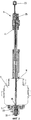
фиг.1 схематично и очень упрощенно изображает на виде сбоку с частичным разрезом устройство для изготовления контейнеров, причем оно показано в рабочем состоянии в ходе процесса изготовления, при котором одна видная на чертеже заливочная штанга проходит своим заливочным игольчатым концом внутрь формы с подвижными составными частями,figure 1 schematically and very simplified depicts a side view in partial section of a device for the manufacture of containers, and it is shown in working condition during the manufacturing process, in which one visible on the drawing, the filling rod extends with its filling needle end into the mold with movable components,
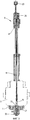
фиг.2 изображает в немного увеличенном виде по сравнению с фиг.1 с частичным разрезом только экструзионную головку и заливочную штангу с предназначенным для нее заливочным устройством, причем заливочная штанга показана в рабочем положении, в котором она входит своим продольным участком в охватывающую насадку, находящуюся в своем функциональном положении на торцевой поверхности экструзионной головки,figure 2 depicts in a slightly enlarged form compared with figure 1 with a partial section only the extrusion head and the casting rod with the intended casting device, and the casting rod is shown in the working position in which it enters its longitudinal section in the covering nozzle located in its functional position on the end surface of the extrusion head,
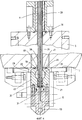
фиг.3 изображает устройство на том же виде, что и на фиг.2, но заливочная штанга втянута в рабочее положение в экструзионной головке, так что охватывающая насадка может быть смещена из своего функционального положения,figure 3 depicts the device in the same form as in figure 2, but the casting rod is retracted into position in the extrusion head, so that the female nozzle can be displaced from its functional position,
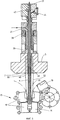
фиг.4 изображает в значительно увеличенном виде по сравнению с фиг.2 и 3, в разрезе и с частичным разрывом устройство в рабочем и функциональном положениях его компонентов,figure 4 depicts in a significantly enlarged form compared with figure 2 and 3, in the context and with a partial rupture of the device in the working and functional positions of its components,
фиг.5 схематично изображает в упрощенном виде в вертикальном разрезе устройство в котором, как и на фиг.1, показана только одна видная на чертеже заливочная штанга и обозначено стерильное пространство, образованное внутри формуемой трубки вдоль наружной стороны заливочной штанги между экструзионной головкой и формой.figure 5 schematically depicts a simplified view in vertical section of a device in which, as in figure 1, shows only one visible on the drawing, the filling rod and the sterile space formed inside the tube formed along the outer side of the filling rod between the extrusion head and the mold.
Осуществление изобретенияThe implementation of the invention
На фиг.1 установка в целом обозначена позицией 1. На ее раме 3 установлена экструзионная головка 5, которая в устройствах данного типа известным образом содержит, по меньшей мере, одно экструзионное сопло (50 на фиг.4 и 5). При работе из этого экструзионного сопла 50 на торцевую поверхность 7 экструзионной головки 5 выходит рукав или трубка (52 на фиг.5), которая образуется из подаваемого к экструзионной головке пластифицированного синтетического материала. Такие экструзионные устройства, например, устройства, работающие способом bottelpack®, сами по себе известны, поэтому нет необходимости в подробном описании конструкции экструзионной головки 5. Следует только отметить, что в установке имеется заливочное устройство 9, по меньшей мере, с одной заливочной штангой 11, которая проходит в экструзионной головке 5 в продольном направлении. Хотя на чертеже показано только одно заливочное устройство 9 с заливочной штангой 11, следует понимать, что экструзионная головка 5 выполнена удлиненной, предпочтительно в направлении, перпендикулярном плоскости чертежа, так что может быть предусмотрено множество заливочных устройств 9 с заливочными штангами 11, расположенных в ряд перпендикулярно плоскости чертежа.In Fig. 1, the installation is generally indicated by 1. On its
Обычным образом для таких устройств заливочная штанга 11 выполнена с возможностью установки в различные выбранные рабочие положения, например, за счет того, что он вместе со своим заливочным устройством 9 установлен с возможностью перемещения на несущем элементе 13 рамы. В любом случае заливочные штанги 11 управляются в цикличном режиме с цикличной установкой в рабочие положения, требуемые для процессов изготовления и заливки, а также для процессов очистки, стерилизации и сушки.In the usual way for such devices, the
На фиг.1 и 5 заливочная штанга 11 показана в выдвинутом рабочем положении для процесса заполнения контейнеров, причем суженный игольчатый концевой участок 15 выдвинут в еще не закрытую форму 17, обращенную к головке. При этом с помощью карусельной системы индивидуальные части 19 формы движутся парами навстречу друг другу по существу по дуговым траекториям, чтобы образовывать закрытую готовую форму, а затем удаляются друг от друга для открытия формы. Для дозированной подачи материала-заполнителя из концевого участка 15 каждая заливочная штанга 11 имеет центральный функциональный канал в виде канала 21, показанного на фиг.4 и 5. Подлежащий заливке продукт подается от центральной питающей линии 23 для материала-заполнителя в управляемые дозирующие блоки 25 каждого заливочного устройства 9. Дозирующие блоки 25 подают в соответствующие заливочные каналы 21 требуемые для каждого процесса заполнения дозированные количества материала-заполнителя с управлением в цикличном режиме.1 and 5, the
В отличие от фиг.1 и 5 на фиг.2-4 показаны рабочие положения, которые соответствующие заливочные штанги 11 занимают во время проведения подготовительных мероприятий перед эксплуатацией в режиме изготовления. При этом на фиг.2 и 4 показано рабочее положение, при котором заливочная штанга 11 отведена из области формы 17 и находится в продольной области охватывающей насадки 27. При этом, как лучше всего видно на фиг.4, речь идет об игольчатом концевом участке 15 с выходным отверстием для материала-заполнителя и примыкающем к нему продольном участке 29. Концевой участок 15 находится в первой функциональной полости 31 внутри охватывающей насадки 27, при этом выходной канал 33 образует выход для среды из полости 31.In contrast to FIGS. 1 and 5, FIGS. 2-4 show the operating positions that the
Примыкающий к концевому участку 15 продольный участок 29 находится в охватывающей насадке 27 во второй функциональной полости 35, для которой также предусмотрен выходной канал (не показан) для отвода среды. Полости 31 и 35 отделены друг от друга с помощью уплотнительного вкладыша 37, через который игольчатый концевой участок 15 проходит в первую полость 31, когда заливочная штанга 11 занимает рабочее положение по фиг.2 и 4.Adjacent to the
Помимо функциональных каналов, таких как центральный заливочный канал 21, которые в устройствах этого типа известным образом проходят в заливочной штанге 11, предусмотрен, по меньшей мере, один дополнительный функциональный канал, который служит каналом подачи среды и обозначен позицией 39 на фиг.4 и 5. Как показано на фиг.4 и 5, этот дополнительный функциональный канал 39 проходит вдоль наружной поверхности соответствующих заливочных штанг 11 от впускного подсоединения 41 (фиг.5) до выходного отверстия 40 на торцевой поверхности 7 экструзионной головки 5. На фиг.5 позициями 42 и 44 обозначены подсоединения, предусмотренные для дополнительных каналов при их наличии, например, для подачи и отвода жидкости для охлаждения заливочной штанги 11.In addition to the functional channels, such as the
В показанном на фиг.2 и 4 рабочем состоянии верхняя стенка 47 корпуса 45 охватывающей насадки 27 плоско прилегает к торцевой поверхности 7 экструзионной головки 5. При этом кромка входного отверстия 51 в верхней стенке корпуса 45 выровнена с выходным отверстием 40 функционального канала 39, так что функциональный канал 39 сообщается через входное отверстие 51 со второй полостью 35. Одновременно первая полость 31 охватывающей насадки 27 сообщается с заливочным каналом 21 через заливочное отверстие на концевом участке 15.In the operating state shown in FIGS. 2 and 4, the upper wall 47 of the
В этом рабочем состоянии могут проводиться все связанные с очисткой и стерилизацией мероприятия благодаря сообщению между каналами 21, 39 заливочной штанги 11 и полостями 31, 35 охватывающей насадки 27. При этом процесс может быть организован таким образом, что через подсоединение питающей линии 23 и включенный на пропуск потока дозирующий блок 25 очищающая жидкость после очистки заливочного канала 21 поступает в функциональную полость 31 и отводится из нее по каналу 33. За счет сообщения между каналом 39 подачи среды и второй функциональной полостью 35 от впускного подсоединения 41 заливочного устройства 9 может подаваться другая среда, так что продольный участок 29 заливочной штанги 11 может очищаться или стерилизоваться со стороны окружной периферии. В этом же рабочем положении заливочной штанги 11 и при находящейся в функциональном положении охватывающей насадке 27 вслед за очисткой заливочного канала 21 может быть запущен процесс стерилизации. При этом через заливочное устройство 9 в заливочный канал 21 подают горячий пар при температуре, по меньшей мере, равной 121°C, который стерилизует не только внутреннюю стенку заливочного канала 21, но также внутренность полости 31 охватывающей насадки 27 и наружную сторону концевого участка 15. Соответствующим образом по каналу 39 подачи среды стерилизующий горячий пар может подаваться в полость 35 охватывающей насадки 27, что обеспечивает стерилизацию также наружной стороны участка 29.In this operating condition, all measures related to cleaning and sterilization can be carried out due to communication between the
Обычным образом для процессов очистки и стерилизации далее через те же самые соединения может проводиться соответствующий процесс сушки и охлаждения, причем конденсат пара от предшествующей стерилизации выдувается путем подачи стерильного воздуха.In the usual way for cleaning and sterilization processes, the corresponding drying and cooling process can then be carried out through the same compounds, and the condensate from the previous sterilization is blown out by supplying sterile air.
Вслед за сушкой соответствующая заливочная штанга 11 втягивается в показанное на фиг.3 рабочее положение, а охватывающая насадка 27 выводится из функционального положения, показанного на фиг.2 и 4. При этом охватывающая насадка 27, например, перемещается по торцевой поверхности 7 экструзионной головки 5 в направлении, перпендикулярном плоскости чертежа.Following the drying, the
После удаления охватывающей насадки 27 из функционального положения устройство готово к началу периода изготовления. Вследствие того, что в ходе показанной на фиг.1 и 5 производственной фазы выходное отверстие 40 проходящего вдоль наружной стороны заливочной штанги 11 функционального канала 39 находится внутри трубки 52, выходящей из отверстия экструзионного сопла 50 (фиг.5), подаваемая по функциональному каналу 39 среда течет внутрь трубки 52. При этом трубка 52 при своем следовании от экструзионной головки 5 до формы 17 образует замкнутое пространство. Таким образом, при подаче через функциональный канал 39 стерильного воздуха образуется стерильное пространство 53 заполнения, внутри которого выполняется весь производственный процесс, то есть вплоть до формования закрытой головки на заполненном контейнере, что производится путем закрытия соответствующих щек формы 17. Поскольку соответствующие механизмы формы сами по себе известны, обозначенная в целом позицией 17 форма показана на чертеже схематично в упрощенном виде без изображения ее основных частей и частей формования головки контейнера.After removing the
Таким образом, благодаря конструкции устройства по изобретению не только достигается стабилизация трубки материала путем подачи поддерживающего воздуха через выходное отверстие 40, но также за счет подачи стерильного воздуха обеспечивается образование стерильной зоны, так что устройство в высокой степени удовлетворяет требованиям международных стандартов в отношении асептики (класс 100).Thus, thanks to the design of the device according to the invention, not only stabilization of the material tube is achieved by supplying support air through the
Claims (9)
- содержит, по меньшей мере, одну функциональную полость (31, 35),
- в своем функциональном положении для целей очистки, и/или стерилизации, и/или сушки устанавливает проводящее среду сообщение между своей соответствующей полостью (31, 35) и предназначенным для нее функциональным каналом (21, 39) заливочного устройства (9), и
- во время изготовления и заполнения контейнеров удалена из своего функционального положения, причем
- охватывающая насадка (27) содержит первую функциональную полость (31) и вторую функциональную полость (35), которые расположены со смещением относительно друг друга в направлении продольного перемещения соответствующей заливочной штанги (11), причем в первую из них функциональную полость (31) входит концевой участок (15) заливочной штанги (11), на котором находится выходное отверстие центрально проходящего в заливочной штанге (11) функционального канала, который служит заливочным каналом (21) при заполнении контейнера.1. A device for the manufacture and filling of containers in which at least one tube of plasticized synthetic material can be extruded into an open mold (17), using at least one filling device (9) having several separate functional channels (21, 39), in the corresponding container through the filling rod (11) intended for the mold (17), at least a filler material can be supplied, characterized in that it contains a nozzle covering the filling rod at (27), which
- contains at least one functional cavity (31, 35),
- in its functional position, for cleaning, and / or sterilization, and / or drying, establishes a conductive medium between its respective cavity (31, 35) and the functional channel (21, 39) of the filling device (9) intended for it, and
- during the manufacture and filling of containers removed from its functional position, and
- the enclosing nozzle (27) contains a first functional cavity (31) and a second functional cavity (35), which are displaced relative to each other in the direction of longitudinal movement of the corresponding casting rod (11), the functional cavity (31) entering the first the end section (15) of the filling rod (11), on which the outlet of the functional channel, which is centrally passing in the filling rod (11), is located, which serves as the filling channel (21) when filling the container.
Applications Claiming Priority (3)
| Application Number | Priority Date | Filing Date | Title |
|---|---|---|---|
| DE102008028754.7 | 2008-06-17 | ||
| DE102008028754A DE102008028754A1 (en) | 2008-06-17 | 2008-06-17 | Device for producing and filling containers |
| PCT/EP2009/004151 WO2009152979A1 (en) | 2008-06-17 | 2009-06-10 | Device for producing and filling containers |
Publications (2)
| Publication Number | Publication Date |
|---|---|
| RU2010153051A RU2010153051A (en) | 2012-07-27 |
| RU2503595C2 true RU2503595C2 (en) | 2014-01-10 |
Family
ID=40984874
Family Applications (1)
| Application Number | Title | Priority Date | Filing Date |
|---|---|---|---|
| RU2010153051/13A RU2503595C2 (en) | 2008-06-17 | 2009-06-10 | Device for manufacturing and filling containers |
Country Status (15)
| Country | Link |
|---|---|
| US (1) | US8480390B2 (en) |
| EP (1) | EP2285685B1 (en) |
| JP (1) | JP5432248B2 (en) |
| KR (1) | KR101498517B1 (en) |
| CN (1) | CN102066199B (en) |
| AU (1) | AU2009259653B2 (en) |
| BR (1) | BRPI0915322B1 (en) |
| CA (1) | CA2725907C (en) |
| DE (1) | DE102008028754A1 (en) |
| ES (1) | ES2425376T3 (en) |
| MX (1) | MX2010013376A (en) |
| PL (1) | PL2285685T3 (en) |
| PT (1) | PT2285685E (en) |
| RU (1) | RU2503595C2 (en) |
| WO (1) | WO2009152979A1 (en) |
Cited By (1)
| Publication number | Priority date | Publication date | Assignee | Title |
|---|---|---|---|---|
| RU2706626C2 (en) * | 2015-06-11 | 2019-11-19 | Кохер-Пластик Машиненбау Гмбх | Method for manufacturing filled and closed container, device for implementing method and container made by said method |
Families Citing this family (16)
| Publication number | Priority date | Publication date | Assignee | Title |
|---|---|---|---|---|
| AU2005306533B2 (en) * | 2004-11-17 | 2012-05-31 | Arbutus Biopharma Corporation | siRNA silencing of apolipoprotein B |
| WO2007051303A1 (en) * | 2005-11-02 | 2007-05-10 | Protiva Biotherapeutics, Inc. | MODIFIED siRNA MOLECULES AND USES THEREOF |
| DE102011008132A1 (en) * | 2011-01-04 | 2012-07-05 | Khs Corpoplast Gmbh | Method and device for blow-molding sterile containers |
| EP2741962B1 (en) * | 2011-08-08 | 2019-10-30 | Discma AG | Method of degasification of a carbonated beverage-filled container |
| BR112014002887B1 (en) * | 2011-08-08 | 2020-09-15 | Discma Ag | ROTATING SYSTEM FOR SIMULTANEOUSLY BLOWING AND FILLING PLASTIC CONTAINERS |
| KR102192486B1 (en) * | 2012-10-16 | 2020-12-17 | 코허-플라스틱 마쉬넨바우 게엠베하 | Device for producing container products consisting of plastic materials |
| DE102017008802A1 (en) | 2017-09-20 | 2019-03-21 | Kocher-Plastik Maschinenbau Gmbh | Device for producing and filling containers |
| DE102017008803A1 (en) | 2017-09-20 | 2019-03-21 | Kocher-Plastik Maschinenbau Gmbh | Device for producing and filling container products |
| CN109204946B (en) * | 2018-10-08 | 2023-12-15 | 广州达意隆包装机械股份有限公司 | Filling dispenser and filling device |
| DE102023001313A1 (en) | 2023-04-03 | 2024-10-10 | Kocher-Plastik Maschinenbau Gmbh | device |
| DE102023004512A1 (en) * | 2023-11-08 | 2025-05-08 | Kocher-Plastik Maschinenbau Gmbh | Device for blow molding and filling containers |
| CN117302646A (en) * | 2023-11-09 | 2023-12-29 | 楚天科技股份有限公司 | A cleaning and sterilization method and device for continuous blow-fill-sealing equipment |
| DE102024002527A1 (en) | 2024-08-02 | 2026-02-05 | Rommelag Engineering Gmbh | device |
| DE102024002690A1 (en) | 2024-08-19 | 2026-02-19 | Rommelag Engineering Gmbh | system |
| CN119139138B (en) * | 2024-11-18 | 2025-02-25 | 山东新华医疗器械股份有限公司 | Mobile filling system |
| DE102025000454B3 (en) * | 2025-02-06 | 2025-07-03 | Kocher-Plastik Maschinenbau Gmbh | Extrusion head for producing tubes as preforms for containers to be formed |
Citations (3)
| Publication number | Priority date | Publication date | Assignee | Title |
|---|---|---|---|---|
| DE19648087A1 (en) * | 1995-11-21 | 1997-05-22 | Bernd Hansen | Sterile filling device for containers |
| EP0785134A2 (en) * | 1996-01-16 | 1997-07-23 | Gruppo Bertolaso S.p.A. | Method and apparatus for sanitizing filling machines and systems, particularly for food products |
| RU2113381C1 (en) * | 1993-02-23 | 1998-06-20 | Юнифилл Интернэшнл А/Г | Method of and device for packing liquid and semiliquid products in containers made of thermally moulded plastic |
Family Cites Families (18)
| Publication number | Priority date | Publication date | Assignee | Title |
|---|---|---|---|---|
| GB1054597A (en) * | 1964-07-10 | |||
| FR2091884B1 (en) * | 1970-03-27 | 1974-05-03 | Raffinage Cie Francaise | |
| JPS618595U (en) * | 1984-06-20 | 1986-01-18 | 澁谷工業株式会社 | Filling valve cleaning device |
| JP2668398B2 (en) * | 1988-07-09 | 1997-10-27 | 株式会社南陽製作所 | Multicolor filling machine for pastes |
| DE3834184C1 (en) * | 1988-10-07 | 1989-12-28 | Bernd 7166 Sulzbach-Laufen De Hansen | |
| JP2698929B2 (en) * | 1989-04-10 | 1998-01-19 | 四国化工機株式会社 | Cleaning equipment in filling equipment of packaging machines |
| DE4205655C2 (en) * | 1992-02-25 | 1999-12-16 | Bosch Gmbh Robert | Method for sterilizing a packaging machine and device for carrying out the method |
| JP3359351B2 (en) * | 1992-05-11 | 2002-12-24 | 日立造船株式会社 | Filling nozzle with self-cleaning function |
| DE4409617A1 (en) * | 1994-03-21 | 1995-09-28 | Bernd Hansen | Device for the sterile filling of containers |
| DE4411629A1 (en) * | 1994-04-02 | 1995-11-02 | Tetra Laval Holdings & Finance | Valve for filling liquids in packaging |
| DE4422713B4 (en) * | 1994-06-29 | 2004-04-08 | Robert Bosch Gmbh | Method for sterilizing parts of a packaging machine and an apparatus for performing the method |
| DE19904131C2 (en) * | 1999-02-03 | 2001-01-04 | Hassia Verpackung Ag | Filling station for an aseptic FFS packaging machine |
| DE10063282C2 (en) * | 2000-12-19 | 2003-06-18 | Bernd Hansen | Method and device for manufacturing and filling containers |
| EP1351858B1 (en) * | 2001-11-07 | 2004-08-25 | Hassia Verpackungsmaschinen GmbH | Method for presterilizing a tubular pouch packing machine |
| CN2576608Y (en) * | 2002-09-17 | 2003-10-01 | 哈尔滨赛德技术发展有限公司 | Vertical bag-with-lid fully automatic liquid-packing machine |
| DE10323335A1 (en) * | 2003-05-23 | 2004-12-16 | Hansen, Bernd, Dipl.-Ing. | Fabrication |
| ITBO20030411A1 (en) | 2003-07-03 | 2005-01-04 | Stk Stocchi Progetti S R L | TAP FOR STERILE FILLING OF FOOD LIQUIDS. |
| DE102004004755A1 (en) * | 2004-01-30 | 2005-08-25 | Bernd Hansen | Method and device for producing and filling containers |
-
2008
- 2008-06-17 DE DE102008028754A patent/DE102008028754A1/en not_active Withdrawn
-
2009
- 2009-06-10 PL PL09765559T patent/PL2285685T3/en unknown
- 2009-06-10 BR BRPI0915322-5A patent/BRPI0915322B1/en active IP Right Grant
- 2009-06-10 ES ES09765559T patent/ES2425376T3/en active Active
- 2009-06-10 KR KR1020107028277A patent/KR101498517B1/en active Active
- 2009-06-10 CA CA2725907A patent/CA2725907C/en active Active
- 2009-06-10 JP JP2011513920A patent/JP5432248B2/en active Active
- 2009-06-10 EP EP09765559.1A patent/EP2285685B1/en active Active
- 2009-06-10 CN CN2009801225103A patent/CN102066199B/en active Active
- 2009-06-10 RU RU2010153051/13A patent/RU2503595C2/en active
- 2009-06-10 MX MX2010013376A patent/MX2010013376A/en active IP Right Grant
- 2009-06-10 PT PT97655591T patent/PT2285685E/en unknown
- 2009-06-10 WO PCT/EP2009/004151 patent/WO2009152979A1/en not_active Ceased
- 2009-06-10 AU AU2009259653A patent/AU2009259653B2/en active Active
- 2009-06-10 US US12/736,639 patent/US8480390B2/en active Active
Patent Citations (3)
| Publication number | Priority date | Publication date | Assignee | Title |
|---|---|---|---|---|
| RU2113381C1 (en) * | 1993-02-23 | 1998-06-20 | Юнифилл Интернэшнл А/Г | Method of and device for packing liquid and semiliquid products in containers made of thermally moulded plastic |
| DE19648087A1 (en) * | 1995-11-21 | 1997-05-22 | Bernd Hansen | Sterile filling device for containers |
| EP0785134A2 (en) * | 1996-01-16 | 1997-07-23 | Gruppo Bertolaso S.p.A. | Method and apparatus for sanitizing filling machines and systems, particularly for food products |
Cited By (1)
| Publication number | Priority date | Publication date | Assignee | Title |
|---|---|---|---|---|
| RU2706626C2 (en) * | 2015-06-11 | 2019-11-19 | Кохер-Пластик Машиненбау Гмбх | Method for manufacturing filled and closed container, device for implementing method and container made by said method |
Also Published As
| Publication number | Publication date |
|---|---|
| PL2285685T3 (en) | 2013-12-31 |
| CN102066199B (en) | 2013-04-03 |
| US8480390B2 (en) | 2013-07-09 |
| BRPI0915322B1 (en) | 2019-08-06 |
| KR101498517B1 (en) | 2015-03-04 |
| EP2285685A1 (en) | 2011-02-23 |
| KR20110017386A (en) | 2011-02-21 |
| HK1154374A1 (en) | 2012-04-20 |
| AU2009259653B2 (en) | 2013-09-05 |
| JP2011524840A (en) | 2011-09-08 |
| AU2009259653A1 (en) | 2009-12-23 |
| CA2725907C (en) | 2015-01-06 |
| EP2285685B1 (en) | 2013-07-10 |
| ES2425376T3 (en) | 2013-10-15 |
| CN102066199A (en) | 2011-05-18 |
| CA2725907A1 (en) | 2009-12-23 |
| JP5432248B2 (en) | 2014-03-05 |
| BRPI0915322A2 (en) | 2015-10-27 |
| WO2009152979A1 (en) | 2009-12-23 |
| US20110076355A1 (en) | 2011-03-31 |
| DE102008028754A1 (en) | 2009-12-24 |
| MX2010013376A (en) | 2010-12-21 |
| PT2285685E (en) | 2013-07-24 |
| RU2010153051A (en) | 2012-07-27 |
Similar Documents
| Publication | Publication Date | Title |
|---|---|---|
| RU2503595C2 (en) | Device for manufacturing and filling containers | |
| US3464085A (en) | Packaging apparatus | |
| CN101992541B (en) | Blow-moulding machine with cleaning system | |
| US9579841B2 (en) | Blow molding device | |
| JP5291082B2 (en) | Equipment that minimizes oxygen content | |
| CN104136195A (en) | Blow-molding device and production method for container | |
| RU2013156311A (en) | METHOD AND DEVICE FOR CLEANING AND / OR DISINFECTION OF A DEVICE FOR MANUFACTURING VESSELS FILLED WITH LIQUID FILLING MATERIAL | |
| HK1224255A1 (en) | Device for producing container products from plastics material | |
| ITMI980347A1 (en) | COOLING AND EXTRACTION SYSTEM FOR INJECTION MOLDED HOLLOW BODIES | |
| KR20060130143A (en) | Container manufacturing and filling method and device | |
| JP2012529391A (en) | Process for manufacturing medical devices | |
| JP5635237B2 (en) | Container to be molded | |
| IT201800002781A1 (en) | ASEPTIC IRON-BLOWER DEVICE FOR A PREFORM IN THERMOPLASTIC MATERIAL | |
| CN111017280B (en) | Sterilizer-Fill Nozzle Assembly for Aseptic Packaging Machines | |
| HK1154374B (en) | Device for producing and filling containers | |
| IT201700012198A1 (en) | IRONING AND BLOWING DEVICE IN ASEPTIC FOR A THERMOPLASTIC PREFORM | |
| CN220923274U (en) | Device for post-treating container products | |
| JP2021154568A (en) | Liquid blow molding device | |
| ITBO20110223A1 (en) | DOSING DEVICE FOR LIQUID PRODUCTS | |
| HK1137707B (en) | Device for minimizing oxygen content |