JP5291082B2 - Equipment that minimizes oxygen content - Google Patents
Equipment that minimizes oxygen content Download PDFInfo
- Publication number
- JP5291082B2 JP5291082B2 JP2010500136A JP2010500136A JP5291082B2 JP 5291082 B2 JP5291082 B2 JP 5291082B2 JP 2010500136 A JP2010500136 A JP 2010500136A JP 2010500136 A JP2010500136 A JP 2010500136A JP 5291082 B2 JP5291082 B2 JP 5291082B2
- Authority
- JP
- Japan
- Prior art keywords
- filling
- medium
- passage
- container
- mandrel
- Prior art date
- Legal status (The legal status is an assumption and is not a legal conclusion. Google has not performed a legal analysis and makes no representation as to the accuracy of the status listed.)
- Active
Links
- QVGXLLKOCUKJST-UHFFFAOYSA-N atomic oxygen Chemical compound [O] QVGXLLKOCUKJST-UHFFFAOYSA-N 0.000 title claims abstract description 48
- 239000001301 oxygen Substances 0.000 title claims abstract description 48
- 229910052760 oxygen Inorganic materials 0.000 title claims abstract description 48
- 239000012530 fluid Substances 0.000 claims abstract 3
- 230000007717 exclusion Effects 0.000 claims description 29
- IJGRMHOSHXDMSA-UHFFFAOYSA-N Atomic nitrogen Chemical compound N#N IJGRMHOSHXDMSA-UHFFFAOYSA-N 0.000 claims description 17
- 229910001873 dinitrogen Inorganic materials 0.000 claims description 13
- 238000000034 method Methods 0.000 claims description 11
- 239000011261 inert gas Substances 0.000 claims description 9
- 230000000903 blocking effect Effects 0.000 claims description 8
- 230000008569 process Effects 0.000 claims description 7
- XKRFYHLGVUSROY-UHFFFAOYSA-N Argon Chemical compound [Ar] XKRFYHLGVUSROY-UHFFFAOYSA-N 0.000 claims description 6
- 238000000071 blow moulding Methods 0.000 claims description 4
- 229910052786 argon Inorganic materials 0.000 claims description 3
- 229910052756 noble gas Inorganic materials 0.000 claims description 3
- 230000002093 peripheral effect Effects 0.000 claims 1
- 238000006073 displacement reaction Methods 0.000 abstract 3
- 238000003466 welding Methods 0.000 description 8
- 230000004888 barrier function Effects 0.000 description 6
- 238000003860 storage Methods 0.000 description 6
- 238000000926 separation method Methods 0.000 description 5
- 238000001125 extrusion Methods 0.000 description 4
- 239000000463 material Substances 0.000 description 4
- 230000001954 sterilising effect Effects 0.000 description 4
- 238000004659 sterilization and disinfection Methods 0.000 description 4
- 239000003708 ampul Substances 0.000 description 3
- 238000005429 filling process Methods 0.000 description 3
- 239000000126 substance Substances 0.000 description 3
- 230000006872 improvement Effects 0.000 description 2
- 238000004519 manufacturing process Methods 0.000 description 2
- 229910052757 nitrogen Inorganic materials 0.000 description 2
- 241000894006 Bacteria Species 0.000 description 1
- 241000233866 Fungi Species 0.000 description 1
- 230000004308 accommodation Effects 0.000 description 1
- 244000052616 bacterial pathogen Species 0.000 description 1
- 230000002349 favourable effect Effects 0.000 description 1
- 239000007789 gas Substances 0.000 description 1
- 230000009545 invasion Effects 0.000 description 1
- 239000007788 liquid Substances 0.000 description 1
- 230000033001 locomotion Effects 0.000 description 1
- 238000000465 moulding Methods 0.000 description 1
- -1 nitrogen gas Chemical compound 0.000 description 1
- 230000003647 oxidation Effects 0.000 description 1
- 238000007254 oxidation reaction Methods 0.000 description 1
- 230000001590 oxidative effect Effects 0.000 description 1
- 238000004806 packaging method and process Methods 0.000 description 1
- 230000009467 reduction Effects 0.000 description 1
- 230000007704 transition Effects 0.000 description 1
Images


Classifications
-
- B—PERFORMING OPERATIONS; TRANSPORTING
- B65—CONVEYING; PACKING; STORING; HANDLING THIN OR FILAMENTARY MATERIAL
- B65B—MACHINES, APPARATUS OR DEVICES FOR, OR METHODS OF, PACKAGING ARTICLES OR MATERIALS; UNPACKING
- B65B31/00—Packaging articles or materials under special atmospheric or gaseous conditions; Adding propellants to aerosol containers
- B65B31/04—Evacuating, pressurising or gasifying filled containers or wrappers by means of nozzles through which air or other gas, e.g. an inert gas, is withdrawn or supplied
- B65B31/044—Evacuating, pressurising or gasifying filled containers or wrappers by means of nozzles through which air or other gas, e.g. an inert gas, is withdrawn or supplied the nozzles being combined with a filling device
-
- B—PERFORMING OPERATIONS; TRANSPORTING
- B65—CONVEYING; PACKING; STORING; HANDLING THIN OR FILAMENTARY MATERIAL
- B65B—MACHINES, APPARATUS OR DEVICES FOR, OR METHODS OF, PACKAGING ARTICLES OR MATERIALS; UNPACKING
- B65B3/00—Packaging plastic material, semiliquids, liquids or mixed solids and liquids, in individual containers or receptacles, e.g. bags, sacks, boxes, cartons, cans, or jars
- B65B3/02—Machines characterised by the incorporation of means for making the containers or receptacles
- B65B3/022—Making containers by moulding of a thermoplastic material
-
- B—PERFORMING OPERATIONS; TRANSPORTING
- B65—CONVEYING; PACKING; STORING; HANDLING THIN OR FILAMENTARY MATERIAL
- B65B—MACHINES, APPARATUS OR DEVICES FOR, OR METHODS OF, PACKAGING ARTICLES OR MATERIALS; UNPACKING
- B65B3/00—Packaging plastic material, semiliquids, liquids or mixed solids and liquids, in individual containers or receptacles, e.g. bags, sacks, boxes, cartons, cans, or jars
- B65B3/003—Filling medical containers such as ampoules, vials, syringes or the like
-
- B—PERFORMING OPERATIONS; TRANSPORTING
- B65—CONVEYING; PACKING; STORING; HANDLING THIN OR FILAMENTARY MATERIAL
- B65B—MACHINES, APPARATUS OR DEVICES FOR, OR METHODS OF, PACKAGING ARTICLES OR MATERIALS; UNPACKING
- B65B3/00—Packaging plastic material, semiliquids, liquids or mixed solids and liquids, in individual containers or receptacles, e.g. bags, sacks, boxes, cartons, cans, or jars
- B65B3/02—Machines characterised by the incorporation of means for making the containers or receptacles
-
- B—PERFORMING OPERATIONS; TRANSPORTING
- B65—CONVEYING; PACKING; STORING; HANDLING THIN OR FILAMENTARY MATERIAL
- B65B—MACHINES, APPARATUS OR DEVICES FOR, OR METHODS OF, PACKAGING ARTICLES OR MATERIALS; UNPACKING
- B65B31/00—Packaging articles or materials under special atmospheric or gaseous conditions; Adding propellants to aerosol containers
- B65B31/04—Evacuating, pressurising or gasifying filled containers or wrappers by means of nozzles through which air or other gas, e.g. an inert gas, is withdrawn or supplied
Landscapes
- Engineering & Computer Science (AREA)
- Mechanical Engineering (AREA)
- Chemical & Material Sciences (AREA)
- Dispersion Chemistry (AREA)
- Filling Of Jars Or Cans And Processes For Cleaning And Sealing Jars (AREA)
- Basic Packing Technique (AREA)
- Vacuum Packaging (AREA)
- Separation Using Semi-Permeable Membranes (AREA)
- Blow-Moulding Or Thermoforming Of Plastics Or The Like (AREA)
- Oxygen, Ozone, And Oxides In General (AREA)
Abstract
Description
本発明は、アンプルのような、充填すべき容器における酸素含有量を最小限に抑える装置に関するものであって、その容器は、好ましくはブロー成形、充填、および、閉鎖工程によって形成され、供給装置によって排除媒体を設けることができ、その排除媒体が容器を閉鎖する前に容器から酸素を排除し、その場合に供給装置は、排除媒体をそれぞれの容器内へ供給可能な、少なくとも1つの媒体供給通路を有し、かつ少なくとも部分的に、それぞれの容器を充填可能な、充填装置の構成要素であって、その場合に充填装置が、充填通路を備えた充填マンドレルを有し、その充填通路から分離されてそれぞれの媒体供給通路が延びており、かつその場合に充填マンドレルがさらに、少なくとも1つの他の媒体移送通路を有している。 The present invention relates to a device for minimizing the oxygen content in a container to be filled, such as an ampoule, which container is preferably formed by a blow molding, filling and closing process, and a feeding device At least one medium supply, in which an exclusion medium can be provided, which excludes oxygen from the container before closing the container, in which case the supply device can supply the exclusion medium into the respective container A filling device component having a passage and capable of at least partially filling a respective container, wherein the filling device has a filling mandrel with a filling passage from the filling passage. Separately, each medium supply passage extends, and in that case the filling mandrel further comprises at least one other medium transport passage.
特許文献1によって、可動の型壁を備えた少なくとも1つの型であって、その型内へ可塑化されたプラスチック材料のホースが押し出し可能であり、その型部分が閉鎖可能であって、それによってそれに設けられた溶接エッジがホースの先頭の端部を溶接して容器底を形成する、前記型と、型に接して容器を成形するために、ホースに作用してそれを拡幅する圧力勾配を発生させる装置と、型の上方でホースを分離することによって充填開口部を形成するために、引き戻された基本位置と作業位置との間で移動可能な、可動の分離部材と、充填開口部を通して容器を充填するために充填位置へ型を移動させるための摺動装置とを有し、その場合に、分離部材の作業位置において充填位置へ通じる型の移動路の上方に位置し、かつ充填開口部を覆うような配置と寸法で、無菌のバリアが設けられており、その場合に無菌のバリアとして、分離部材として用いられる刃と共に移動可能な、菌を殺す温度に加熱されるプレートが設けられている、アンプルのような容器を形成して充填する装置が知られている。さらに、この欧州特許によって、この装置を使用してこのような容器を形成するための方法が知られている。 According to U.S. Pat. No. 6,057,056, at least one mold with a movable mold wall, a plastic material hose plasticized into the mold can be extruded and its mold part can be closed, thereby The welding edge provided on it welds the leading end of the hose to form the container bottom, the mold, and the pressure gradient acting on the hose to widen it to form the container in contact with the mold Through the filling opening, a movable separating member movable between the retracted basic position and the working position to form a filling opening by separating the hose above the mold and the generating device A sliding device for moving the mold to the filling position for filling the container, in which case it is located above the movement path of the mold leading to the filling position at the working position of the separating member, and the filling opening Part In such an arrangement and size, a sterile barrier is provided. In this case, a sterile barrier is provided which is movable with a blade used as a separating member and heated to a temperature for killing bacteria. Devices for forming and filling containers such as ampoules are known. Furthermore, a method for forming such a container using this device is known from this European patent.
たとえば、滅菌梱包のための国際標準が満たされなければならない、特殊な薬品の形式の、極めてセンシティブな製品が形成される場合に、型は、それが充填位置へ移動されている場合に、無菌空気が容器の開放した充填開口部を介して流れて、菌の侵入に対する有効な保護を形成する、いわゆる詰替え無菌室(ASR)の下方に位置し、充填工程の終了後まで型の可動のヘッドジョウが閉鎖されて、それによって組み合わされた真空−溶接工程によって容器の所望のヘッド閉鎖が形成される。無菌のバリアに基づいて、型が詰替え無菌室(ASR)に達する前に、ホースの分断後に異物が開放した充填開口部内へ落ちることが防止され、さらに、無菌のバリアは、この方法部分の間、充填開口部への菌の望ましくない接近も、防止する。 For example, when a highly sensitive product is formed in the form of a special chemical that must meet international standards for sterilization packaging, the mold is sterile when it is moved to the filling position. Located under the so-called refill sterilization chamber (ASR), where the air flows through the open filling opening of the container and forms an effective protection against the invasion of the fungus, and is movable until the end of the filling process The head jaws are closed, thereby forming the desired head closure of the vessel by a combined vacuum-welding process. Based on the sterile barrier, foreign material is prevented from falling into the open filling opening after the hose breaks before the mold reaches the refill sterilization chamber (ASR), and the sterile barrier is Meanwhile, unwanted access of germs to the filling opening is also prevented.
しかし、アンプルのような容器製品内へ詰め替えられる、高価値の薬品を含む酸素に敏感な製品が、さらにそれぞれの容器内の残留酸素含有量と接触し、それが特に、詰め替えられた製品における、特に酸化の形式の損傷プロセスをもたらすことが、明らかにされており、それが特に、可能な保管長さの著しい減少を伴う。従って今日では、敏感な製品においては、詰め替えられた製品から自由に保たれる、容器の頭部空間内の、0.5%より少なく、好ましくは0.2%より少ない、残留酸素割合が、要求される。この要請に、上述した無菌のバリア装置も、たとえば特許文献2または特許文献3によって示されるような、その他の既知の製造方法および装置も、十分に対応し得ない。 However, oxygen-sensitive products containing high-value chemicals that are refilled into container products such as ampoules also come into contact with the residual oxygen content in each container, which is particularly the case in refilled products, It has been shown to result in a particularly oxidative form of the damage process, which is particularly accompanied by a significant reduction in possible storage length. Therefore, today, in sensitive products, the residual oxygen percentage in the container head space, which is kept free from the refilled product, is less than 0.5%, preferably less than 0.2%. Required. Neither the above-described aseptic barrier device nor the other known manufacturing methods and devices shown in, for example, Patent Document 2 or Patent Document 3 can sufficiently respond to this request.
このことは、最終的に、アンプルのような、充填すべき容器において酸素含有量を最小限に抑えるために、供給装置を用いて供給されて、容器の閉鎖前に容器から酸素を追い出す排除媒体を使用する装置にも当てはまる。すなわち、特許文献4は、充填された容器の自由な容器開口部の上方へ移動される供給装置を用いて、排除媒体として不活性ガスが容器開口部の方向へ吹き出されて、それによって容器開口部からの排除により酸素含有量を減少させる、装置解決を示している。 This ultimately means an exclusion medium, such as an ampoule, that is supplied using a supply device to expel oxygen from the container before the container is closed in order to minimize the oxygen content in the container to be filled. This also applies to devices that use. That is, in Patent Document 4, an inert gas is blown out in the direction of the container opening as an exclusion medium using a supply device that is moved above the free container opening of the filled container, thereby opening the container Figure 2 shows an apparatus solution that reduces the oxygen content by eliminating from the part.
特許文献5によって、容器としてのアンプルを充填して閉鎖する方法が知られており、その方法において、容器内へ投入すべき製品を供給するための充填通路を備えた充填マンドレルが、媒体供給通路によって同心の配置で包囲されており、その媒体供給通路は外側へ向かって、供給装置の壁部分によって包囲されて、不活性ガスの形式の排除媒体を供給するために用いられ、それによって容器の内部の酸素含有量が最小限に抑えられる。
特許文献6によって、同心配置の種々の媒体給送通路を備えた供給装置を有し、その場合に一番内側の通路が、充填マンドレルの充填通路を形成する、ビン製品のような充填すべき容器において、酸素含有量を最小限に抑える、この種概念の装置が知られている。充填通路を包囲する、不活性ガスの形式の排除媒体のための媒体供給通路がまた、媒体搬出通路によって包囲されており、その媒体排出通路がそれぞれの容器から酸素の他に排除媒体を搬出するために用いられる(3−パイプ−解決)。酸素含有量を最小限に抑える、この既知の装置の特に好ましい実施形態においては、充填された製品を有する容器の内部へ排除媒体を脈動して投入するために、さらに他の媒体供給通路が、第1の媒体供給通路と一番外側に位置する媒体搬出通路の間に同心の配置で配置されている(4−パイプ−解決)。この既知の解決の代替的な形態において、それぞれの容器についてスペース状況がそれを許す限りにおいて、装置の内部に上述した媒体通路を互いに分離して線形に並べて配置して設けることも、提案される。その限りにおいて、各解決変形例において媒体供給の領域内で大きく構成される、最小限に抑える装置は、排除される酸素の大きい体積ももたらすので、この既知の解決も、それぞれの容器の自由な頭部領域内に0.2から0.5%の残留酸素含有量という、必要な設定をもたらすのには、適していない。 According to U.S. Pat. No. 6,057,056, it has a feeding device with various concentric media feeding passages, in which the innermost passage forms the filling passage of the filling mandrel and should be filled like a bottle product Devices of this kind are known that minimize the oxygen content in the container. A medium supply passage for the exclusion medium in the form of an inert gas surrounding the filling passage is also surrounded by a medium discharge passage, which discharges the exclusion medium in addition to oxygen from the respective container (3-pipe-solution). In a particularly preferred embodiment of this known device that minimizes the oxygen content, a further medium supply passage is provided to pulsate the exclusion medium into the container with the filled product, A concentric arrangement is arranged between the first medium supply path and the outermost medium carry-out path (4-pipe-solution). In an alternative form of this known solution, it is also proposed to provide the above-mentioned media passages in the apparatus in a linearly arranged manner separated from each other, as long as the space situation allows for each container. . To that extent, this known solution is also free for each container, since the minimizing device, which is configured largely in the area of media supply in each solution variant, also provides a large volume of oxygen to be excluded. It is not suitable for providing the required setting of 0.2 to 0.5% residual oxygen content in the head region.
従って、この従来技術に基づいて、本発明の課題は、既知の装置を、それが製造工程の間酸素含有量を、それぞれの容器の自由な頭部領域内の0.2から0.5%の残留酸素含有量という、必要な設定に抑えることを可能にするように、さらに改良することである。この課題は、その全体において特許請求項1の特徴を有する装置によって、解決される。 Thus, based on this prior art, the object of the present invention is to provide a known device that reduces the oxygen content during the production process from 0.2 to 0.5% in the free head area of the respective container. This is a further improvement so that the residual oxygen content can be reduced to the required setting. This problem is solved by an apparatus having the features of claim 1 in its entirety.
特許請求項1の特徴部分に従って、充填通路の自由な横断面が、充填マンドレルの、より大きい横断面の環状通路領域内で案内されており、かつ環状通路領域の内部で充填通路がそれぞれの媒体供給通路をそれぞれの媒体移送通路から媒体密に分離していることによって、充填すべき容器における酸素含有量を最小限に抑えるための、極めて小さく構成される装置が形成されるので、その後もはや排除できない空気によって満たされる可能性のある「デッドルーム」は、わずかしか生じず、それによってそうでない場合に存在する酸素の0.2から0.5%の低い残留酸素含有量が得られる。好ましくはアルゴンのような貴ガス、あるいは窒素ガスのような不活性ガスからなる、排除媒体は、供給装置によってそれぞれの容器内へ次のように、すなわち容器を閉鎖する前に残留酸素を容器からほぼ完全に排除するように、注ぎ込むことができるので、極めて酸素に敏感な、容器内にストックされている製品に負担となる、上述した酸化プロセスが回避され、それが製品全体の長い貯蔵可能性を支援する。 According to the characterizing part of claim 1, the free cross section of the filling passage is guided in the annular passage area of the larger cross section of the filling mandrel, and the filling passage is within the annular passage area in the respective medium. Separation of the supply passages from the respective media transfer passages in a medium-tight manner forms a very small device for minimizing the oxygen content in the container to be filled, which is no longer eliminated thereafter. “Dead room”, which can be filled by incapable air, occurs only slightly, resulting in a low residual oxygen content of 0.2 to 0.5% of the oxygen present otherwise. The exclusion medium, preferably consisting of a noble gas such as argon, or an inert gas such as nitrogen gas, is carried into the respective container by means of a supply device as follows: residual oxygen is removed from the container before closing the container. As it can be poured almost completely out, it avoids the oxidation process described above, which imposes a burden on products that are very oxygen sensitive and stocked in containers, which means that the entire product has a long storage potential. To help.
本発明に基づく装置の好ましい実施形態において、媒体移送通路は、それぞれの容器から酸素の他に排除媒体を搬出するため、あるいはそれぞれの容器内へ排除媒体を供給するために用いられる。従って前者の場合において、それぞれの媒体供給通路を介して排除媒体が供給され、容器から酸素と共に排除媒体を搬出するために、媒体移送通路が媒体搬出通路として形成されている。後者の場合には、媒体移送通路は、他の媒体供給通路として形成されているので、組込み空間から小さく抑えられる供給状況にもかかわらず、最大程度の供給すべき排除媒体が得られ、それによって酸素含有量が極めて効率的に最小限に抑えられる。それぞれの媒体供給通路を介しても、それぞれの媒体移送通路を介しても、排除媒体が供給される場合には、排除媒体は、排除すべき空気酸素と共に、供給装置の外部においても、容器から直接周囲へ排除することができる。 In a preferred embodiment of the device according to the invention, the medium transfer passage is used to carry out the exclusion medium in addition to oxygen from each container or to supply the exclusion medium into each container. Therefore, in the former case, the exclusion medium is supplied through the respective medium supply passages, and the medium transfer passage is formed as a medium discharge passage in order to carry out the exclusion medium together with oxygen from the container. In the latter case, since the medium transfer passage is formed as another medium supply passage, the maximum amount of rejected medium to be supplied can be obtained regardless of the supply situation that can be kept small from the built-in space. The oxygen content is minimized very efficiently. When the exclusion medium is supplied through the respective medium supply passages or through the respective medium transfer passages, the exclusion medium is removed from the container outside the supply apparatus together with the air oxygen to be excluded. It can be eliminated directly to the surroundings.
充填マンドレルの環状通路領域の内部に互いに対して媒体密に分離して配置されている、充填通路、媒体供給通路および媒体移送通路が、同じ供給および/または排出方向を有する場合にも、必要とする組込み空間を最小限に抑えるのに役立つ。それによってもたらされる、通路の平行配置は、個々の媒体の流れ的に好ましい移送も許す。 Even when the filling passage, the medium supply passage and the medium transfer passage, which are arranged in a medium-tight separation with respect to each other inside the annular passage area of the filling mandrel, have the same supply and / or discharge direction. Helps to minimize embedded space. The resulting parallel arrangement of the passages also allows a fluidly favorable transfer of the individual media.
本発明に基づく装置の特に好ましい実施形態において、充填マンドレルの環状通路領域は、横断面で見て円形に形成されており、充填通路を画成する、充填マンドレルの壁が、横断面において横方向に減少された長円を形成し、その長円は縦方向において円環状の環状通路領域の内壁に当接し、それによってその限りにおいて形成される、媒体供給通路と媒体移送通路の三日月形状の自由な横断面が、互いに分離される。それによって特に場所をとらないやり方で、すべての媒体通路が供給装置の中央にまとめられる。 In a particularly preferred embodiment of the device according to the invention, the annular passage area of the filling mandrel is circular when viewed in cross section and the walls of the filling mandrel defining the filling passage are transverse in the cross section. An ellipse reduced in the longitudinal direction, and the ellipse abuts the inner wall of the annular annular passage area in the longitudinal direction, thereby forming a crescent-shaped freedom of the medium supply passage and the medium transfer passage Cross sections are separated from one another. Thereby, all media paths are brought together in the center of the supply device in a particularly space-saving manner.
上述した排除結果は、好ましくは媒体供給通路として形成された、他の媒体通路が、充填マンドレルの壁に対して同心の配置で、この壁を包囲して設けられており、その場合に他の媒体通路が外側へ向かって供給装置の他の壁によって包囲されている場合に、さらに改良される。さらにそれに加えて、あるいはその代りに、他の供給装置を用いて少なくとも部分的にそれぞれ充填すべき容器の周囲領域に遮断媒体を設けることができる。このようにしてそれぞれの容器開口部の周囲領域内の酸素含有量も減少され、それが、酸素含有量を最小限に抑える結果の改良に寄与する。 The above exclusion results show that another medium passage, preferably formed as a medium supply passage, is provided concentrically with the wall of the filling mandrel and surrounds this wall, in which case A further improvement is provided if the media passage is surrounded outwardly by another wall of the feeding device. In addition or alternatively, a blocking medium can be provided in the surrounding area of the container to be filled at least partly using other supply devices. In this way, the oxygen content in the area surrounding each container opening is also reduced, which contributes to an improved result of minimizing the oxygen content.
本発明に基づく装置の他の好ましい形態が、その他の下位請求項の対象である。 Other preferred forms of the device according to the invention are the subject of other subclaims.
以下、図面に示す2つの実施例を用いて、本発明に基づく装置を詳細に説明する。その場合に、図は、原理的であって、寸法通りの表示ではない。 In the following, the device according to the present invention will be described in detail using two embodiments shown in the drawings. In that case, the figure is in principle and not a dimensional representation.
図1と2は、既知の(登録商標)bottelpack−システムの枠内で、ブロー成形方法でプラスチック容器を形成するために利用されるような、装置の一部を示しており、その場合に押出し装置1を用いて、溶融されたプラスチック材料からなるホース3が、図1に開放した状態で示される、型6の2つの型半体5の間へ押し出される。ホース3を開放された型6内へ押し出した後に、ホース3は、押出し装置1のノズル出口と型6の上側との間で切断される。図1において、分離線が破線で表示されて、符号8で示されている。
FIGS. 1 and 2 show a part of the apparatus as used to form a plastic container in a blow molding process within the framework of the known (registered trademark) bottompack-system, in which case the extrusion Using the device 1, a hose 3 made of a molten plastic material is pushed between two
図2は、型6を一部閉鎖された状態で示しており、その場合にホース3から形成すべき容器12の主要部分のための形を与える部分、すなわち型半体5は、ホース3を底側の溶接継目9において閉鎖するために、底側の溶接エッジ7がホース3の下方の端部において溶接工程を実施するように、合わせられている。
FIG. 2 shows the mold 6 in a partially closed state, in which case the part giving the shape for the main part of the
図2は、さらに、型6を充填位置で示しており、型は、図1に示す、押出し装置1に整合された位置から充填位置へ側方に摺動されている。この充填位置において、その前に形成されて、図示されないブロー突起を用いて開放した充填開口部15を通してブロー空気を吹き込まれている容器12は、充填開口部15を介して、たとえば液状の薬品の形式の充填物を充填される。図2は、この目的のために充填開口部15内へ導入された充填マンドレル17の端部を示している。充填マンドレル17とその前に導入されたブロー突起の代わりに、容器の成形と充填は、組み合わされたブロー型−充填マンドレルを用いて行うこともできる。容器12は、ブロー突起を介して投入される圧縮空気の代わりに、型へ印加される真空によっても、成形することができる。2つの方法を互いに組み合わせることもできる。
FIG. 2 further shows the mold 6 in the filling position, the mold being slid laterally from the position shown in FIG. 1 aligned with the extrusion device 1 to the filling position. In this filling position, the
図2に示す充填位置において、型は、いわゆる詰替え無菌室(ASR)の下方に位置し、その詰替え無菌室は、図2には簡単にするために図示されておらず、先行する分離工程によって図1に示唆する分離線8においてホース3に形成された充填開口部15の無菌のシールドとして作用する。容器12の充填後に、充填マンドレル17が上方へ取り去られ、型6のまだ開放している、移動可能な上方の溶接ジョウ13が、容器に形を与え、かつ/または同時に溶接によって容器を閉鎖するために、合体される。図1と2に示す溶接ジョウ13によって、容器ネックにねじキャップのための外ねじを形成することも可能であって、そのねじキャップは、溶接による閉鎖に加えて、たとえば内部に突刺し針を有するねじキャップの形式で、設けることができる。さらに、複数の容器を型工具の並べて配置したキャビティ内で成形し、充填し、かつ閉鎖することができる(図示せず)。
In the filling position shown in FIG. 2, the mold is located below the so-called refill sterilization chamber (ASR), which is not shown in FIG. The process acts as a sterile shield for the filling
図1と2に示す成形工具5、13は、図3と5を見る視線方向に従って示されている。本発明に基づく装置は、好ましくはブロー成形−、充填−および閉鎖方法に従って完全に形成された、図示のような、充填すべき容器12において、酸素含有量を最小限に抑えるために用いられる。そのような酸素含有量は、特に、図2の表示に示す中空室19内で、投入された製品の最大充填高さと容器の頭部上側における容器終端との間にある。
The forming
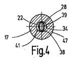
ここでこのように残っている残留酸素を中空室19から排除するために、全体を符号20で示す供給装置が設けられており、その供給装置が排除媒体を中空室19内へ供給し、その排除媒体が容器12の閉鎖前に酸素を容器から排除する。その場合に排除媒体として、好ましくは、窒素ガスのような不活性ガスが使用される。供給装置20は、窒素ガスのための媒体供給通路22を有しており、その限りにおいてその窒素ガスが、それぞれの容器12の中空室19内へ供給可能である。このような媒体供給通路22が、IV−IV線に沿った供給装置20の横断面を示す、図4に示されている。
Here, in order to exclude the residual oxygen remaining in this way from the
さらに図3に示すように、媒体供給通路22は、最小限に抑える装置の上方の終端部分において、拡幅された環状通路24へ移行するように案内されており、その環状通路を介して外部から適当な移送通路(図示せず)を介して排除媒体としての窒素ガスを供給することができる。図3と4からさらに明らかなように、その限りにおいて供給装置20は、充填装置26の構成要素であって、その充填装置を用いてそれぞれの容器12に、ストックされている製品を充填することができる。容器12を充填するために、充填装置26がすでに説明した充填マンドレル17を使用し、その充填マンドレルは中央に配置された充填通路28を有しており、その場合に充填マンドレルはその、図3を見る視線方向において上方の自由端部において、そのために一般的な収容装置30内に保持されており、その収容装置の中央通路32を介して容器12内へ製品の供給が行われる。このような収容および供給装置は、一般的であるので、ここではそれについてこれ以上詳しく説明しない。
Further, as shown in FIG. 3, the
さらに、上述した充填マンドレル17は、搬出通路としての媒体移送通路34を有しており、その搬出通路は、図4に横断面で示されており、それぞれの容器12の残っている中空室19から酸素の他に排除媒体を搬出するために用いられる。このような媒体搬出通路34は、図3を見る視線方向で上の自由端部において、他の環状通路36内で終わっており、その環状通路は、第1の環状通路24の下方に配置されており、かつ装置全体の搬出導管(図示せず)に接続されており、その搬出導管から排除媒体としての窒素を残留酸素と共に容器12から搬出することができる。
Further, the above-described
詳しく図示されない真空装置を介して、このような搬出がさらに支援され、しかしその場合に調節すべき負圧は、容器12内へ投入された製品が容器から不用意に吸い出されないように、選択される。窒素ガスのような、排除媒体の供給すべき量も、中空室19の内部の酸素の自由な体積に加えて容器12の自由な頭部横断面に合わせられる。
Such unloading is further supported via a vacuum device not shown in detail, but the negative pressure to be adjusted in that case is selected so that the product put into the
その他、充填通路28および媒体供給通路22と媒体搬出通路34は、互いに対して平行に、しかし互いに分離されて、細長い充填マンドレル17の内部に延びている。このような媒体分離は、特に、充填通路28の自由な横断面が、横断面においてより大きい環状通路領域38内で案内されていることを示す、図4の横断面表示から明らかにされ、その場合にすでに説明したように、充填通路28がそれぞれの媒体供給通路22をそれぞれの媒体搬出通路34からガス密に分離している。そのために、環状通路領域38は、横断面で見て円形に形成されており、充填通路28を画成する壁39が、横断面において横方向に減少された長円を形成し、その長円が縦方向において、円環状の環状通路領域38の内壁41に当接し、それによって通路22と34の三日月形の自由な横断面が互いに分離される。このようにして充填マンドレル17の狭い組立て空間上でそれぞれ所望の媒体移送が達成され、その場合に排除媒体が媒体供給通路22から流出した後に、反転矢印方向40において、排除媒体が残留酸素と共に再び媒体搬出通路34内へ流入する。このようにして、上方の溶接ジョウ13を介しての容器の本来の閉鎖前に、中空室19内の残留酸素含有量が、極めてわずかな量まで減少する。
In addition, the filling
さらに、図3に示すように、収容装置30の他の供給装置の供給室42を介して、付加的に、好ましくは窒素ガスの形状の遮断媒体が供給され、その遮断媒体は、図3を見る視線方向に見て、収容装置30の下側においてリング状の遮断通路44を介して下方へ向かって外部へ流出し、その限りにおいて窒素ガスによって形成される遮断カーテンを形成し、その遮断カーテンが、周囲酸素が容器12の自由な充填開口部の方向に自由に接近することを、補助的に防止する。この措置に基づいて、容器12の中空室19内の残留酸素含有量が、場合によってはさらに減少される。窒素ガスの流れ方向が、矢印で示されている。
Furthermore, as shown in FIG. 3, a blocking medium, preferably in the form of nitrogen gas, is additionally supplied via a
図5に示す他の実施形態は、供給装置20と充填装置26に関する原則的な構造から、図3に示す構造に相当する。しかし今回は、2つの通路24と36を介して、好ましくは圧力下にある窒素ガスの形式の、排除媒体が供給されて、2つの対向する媒体通路22と34を介して容器12の内部へ同時に吹き込まれ、それは、中央に配置された充填通路28を介しての充填工程の間も行うことができる。その場合に余分な窒素ガスは、流出矢印が示すように、周囲へ吹き出されて、その場合に残留酸素も一緒に案内されるので、その限りにおいてこの変更された実施形態によっても、容器12内の酸素含有量を最小限に抑えることが可能である。連続的な窒素供給によって、空気は容器12の頭部領域内で、図示のように、外側へ排除される。具体的な充填工程を保証することができるようにするために、好ましくは、充填マンドレル17の自由端部とそれに伴って充填通路28が、媒体通路22と34の自由な流入および流出端部に対して軸方向に突出している。従ってこのような実施形態においては、媒体移送通路34は、他の媒体供給通路として用いられる。
The other embodiment shown in FIG. 5 corresponds to the structure shown in FIG. 3 from the basic structure related to the
図5に示す実施形態に基づく他の媒体通路45は、周側に充填マンドレル17の壁47を有し、外側に向かっては供給装置20の他の壁49によって包囲されている。さらに、媒体通路45は、通路36を介して排除媒体を供給される。さらに、図5から明らかなように、媒体通路45の自由端部は、充填マンドレル17の自由端部に対して引っ込んでおり、それによって容器開口部のために、不活性ガスのような遮断媒体による有効な遮断カーテンが得られる。好ましくは、充填マンドレル17がすでに取り外しに入っている場合に、容器12のためのまだ開放している成形ホース内へ遮断ガスが吹き込まれる。成形工具のヘッドジョウ13が、そしてその限りにおいて容器開口部が閉鎖されるまで、外側の媒体通路45を通して、不活性ガスが持続的に流れる。周囲空気に対して均一に遮断カーテンを形成するために、図5の表示に基づく、充填マンドレル17を包囲する媒体通路45が、図3に示す上述した装置と次のように、すなわち、媒体通路45が、その他の媒体通路22、28、34を有する充填マンドレル17を包囲するように、組み合わされ、それは特に、上述した充填マンドレル17がすでに取り外しに入っている場合に、効果的である。
The other
本発明に基づく装置によって、容器製品内の残留酸素が、0.5%より下に、そしてさらに0.2%以下の領域へ低下する。 With the device according to the invention, the residual oxygen in the container product is reduced below 0.5% and further to the region below 0.2%.
Claims (8)
容器はブロー成形により形成され、その後充填および閉鎖工程がおこなわれ、
容器は、供給装置(20)によって容器の閉鎖前に容器から酸素を排除する排除媒体を供給することができ、
供給装置(20)は、少なくとも1つの媒体供給通路(22)を有し、媒体供給通路(22)によって排除媒体をそれぞれの容器(12)内へ供給することができ、
媒体供給通路(22)は少なくとも部分的に充填装置(26)の構成要素であって、充填装置(26)はそれぞれの容器(12)を充填可能であって、
充填装置(26)が充填マンドレル(17)を有し、充填マンドレル(17)が充填通路(28)と、充填通路(28)から分離された媒体供給通路(22)と、少なくとも1つの他の媒体移送通路(34)を有しており、
充填通路(28)の横断面が、充填マンドレル(17)の、横断面のより大きい環状通路領域(38)内で案内されており、かつ、
環状通路領域(38)の内部で、充填通路(28)の壁が、媒体供給通路(22)を、媒体移送通路(34)から媒体密に分離している、ものであって、
充填マンドレル(17)の環状通路領域(38)が、横断面で見て円形に形成されており、かつ、充填マンドレル(17)の、充填通路(28)を画成する壁(39)が、横断面において横方向に減少された長円を形成し、長円が縦方向において円環状の環状通路領域(38)の内壁(41)に当接し、それによって媒体供給通路(22)と媒体移送通路(34)の三日月形の横断面が、互いに分離される、
ことを特徴とする、充填すべき容器における酸素含有量を最小限に抑える装置。 Ampoules, such as a device to minimize the oxygen content in the container (12) to be filled,
The container is formed by blow molding, followed by filling and closing processes,
The container can be supplied with an exclusion medium that excludes oxygen from the container before the container is closed by means of a supply device (20),
The supply device (20) has at least one medium supply passage (22), through which the exclusion medium can be supplied into the respective container (12) by means of the medium supply passage (22),
The medium supply passage (22) is at least partly a component of the filling device (26), the filling device (26) being capable of filling the respective container (12),
The filling device (26) has a filling mandrel (17), the filling mandrel (17) is filled with a filling passage (28), a medium supply passage (22) separated from the filling passage (28), and at least one other A medium transfer passage (34);
The cross section of the filling passage (28) is guided in the annular passage area (38) of the filling mandrel (17) with a larger cross section; and
Inside the annular passage area (38), the wall of the filling passage (28) separates the medium supply passage (22) from the medium transport passage (34) in a medium-tight manner,
An annular passage region (38) of the filling mandrel (17) is formed in a circle when viewed in cross section, and a wall (39) of the filling mandrel (17) defining the filling passage (28) is In the cross section, an ellipse reduced in the transverse direction is formed, and the ellipse abuts on the inner wall (41) of the annular annular passage region (38) in the longitudinal direction, whereby the medium supply passage (22) and the medium transfer The crescent-shaped cross sections of the passageway (34) are separated from each other;
A device for minimizing the oxygen content in the container to be filled.
Applications Claiming Priority (3)
| Application Number | Priority Date | Filing Date | Title |
|---|---|---|---|
| DE102007015078.6 | 2007-03-29 | ||
| DE102007015078A DE102007015078A1 (en) | 2007-03-29 | 2007-03-29 | Device for minimizing the oxygen content |
| PCT/EP2008/002399 WO2008119494A1 (en) | 2007-03-29 | 2008-03-27 | Device for minimizing oxygen content |
Publications (3)
| Publication Number | Publication Date |
|---|---|
| JP2010522670A JP2010522670A (en) | 2010-07-08 |
| JP2010522670A5 JP2010522670A5 (en) | 2011-04-07 |
| JP5291082B2 true JP5291082B2 (en) | 2013-09-18 |
Family
ID=39523642
Family Applications (1)
| Application Number | Title | Priority Date | Filing Date |
|---|---|---|---|
| JP2010500136A Active JP5291082B2 (en) | 2007-03-29 | 2008-03-27 | Equipment that minimizes oxygen content |
Country Status (15)
| Country | Link |
|---|---|
| US (1) | US9150317B2 (en) |
| EP (1) | EP2125524B1 (en) |
| JP (1) | JP5291082B2 (en) |
| KR (1) | KR101454185B1 (en) |
| CN (1) | CN101641257B (en) |
| AT (1) | ATE532708T1 (en) |
| AU (1) | AU2008234135B2 (en) |
| CA (1) | CA2681437C (en) |
| DE (1) | DE102007015078A1 (en) |
| ES (1) | ES2374853T3 (en) |
| HK (1) | HK1137707A1 (en) |
| MX (1) | MX2009010408A (en) |
| PL (1) | PL2125524T3 (en) |
| PT (1) | PT2125524E (en) |
| WO (1) | WO2008119494A1 (en) |
Families Citing this family (11)
| Publication number | Priority date | Publication date | Assignee | Title |
|---|---|---|---|---|
| DE102010028499B4 (en) | 2010-05-03 | 2023-11-23 | Syntegon Technology Gmbh | Combined filling and gassing device |
| EP2794230B1 (en) * | 2011-12-21 | 2018-05-09 | Discma AG | Molding machine comprising a sealing system, and related molding method |
| MX2014013218A (en) | 2012-04-30 | 2014-12-08 | Ge Healthcare As | Method for filling a container with a foamable composition. |
| DE102014104874A1 (en) * | 2014-04-04 | 2015-10-08 | Krones Ag | Apparatus and method for producing a plastic bottle and filling it with a filling product |
| AU2017256152B2 (en) | 2016-04-25 | 2022-04-21 | Koska Family Ltd | Medical delivery system |
| DE102017008802A1 (en) * | 2017-09-20 | 2019-03-21 | Kocher-Plastik Maschinenbau Gmbh | Device for producing and filling containers |
| DE102017008803A1 (en) * | 2017-09-20 | 2019-03-21 | Kocher-Plastik Maschinenbau Gmbh | Device for producing and filling container products |
| KR102639913B1 (en) | 2017-11-17 | 2024-02-23 | 코스카 패밀리 리미티드 | Systems and methods for fluid transfer manifolds |
| US20190350810A1 (en) * | 2018-05-18 | 2019-11-21 | Baxter International Inc. | Dual chamber flexible container and drug product using same |
| US10961003B2 (en) * | 2018-06-07 | 2021-03-30 | Weiler Engineering, Inc. | Telescoping fill station shroud for a blow/fill/seal packaging machine |
| USD992110S1 (en) | 2021-08-10 | 2023-07-11 | Koska Family Limited | Sealed fluid container |
Family Cites Families (19)
| Publication number | Priority date | Publication date | Assignee | Title |
|---|---|---|---|---|
| DE1566547A1 (en) * | 1967-01-10 | 1970-01-08 | Sickel Dr Helmut | Method for filling and sealing ampoules |
| DE2208909A1 (en) * | 1972-02-25 | 1973-09-06 | Pmd Entwicklungswerk | BLOWING AND FILLING PIN |
| US4305242A (en) * | 1978-12-05 | 1981-12-15 | Generale D'entreprise De Conditionnement | Vacuum bagging device with a flexible spout and programming system |
| DE3834184C1 (en) * | 1988-10-07 | 1989-12-28 | Bernd 7166 Sulzbach-Laufen De Hansen | |
| JP2877482B2 (en) | 1990-10-11 | 1999-03-31 | 大日本印刷株式会社 | Stretch blow molding container manufacturing equipment |
| US5394908A (en) * | 1993-12-13 | 1995-03-07 | Trw Vehicle Safety Systems Inc. | Apparatus and method for filling a container |
| US5551213A (en) * | 1995-03-31 | 1996-09-03 | Eastman Kodak Company | Apparatus and method for vacuum sealing pouches |
| FR2760544A1 (en) | 1997-03-04 | 1998-09-11 | Vernet Sa | QUICK MOUNT THERMOSTAT |
| CN2313854Y (en) * | 1997-12-24 | 1999-04-14 | 陈洪 | Apparatus for filling, sealing and packing bags |
| US6112780A (en) * | 1998-04-03 | 2000-09-05 | Meheen; David M. | 4-tube apparatus for gaseous contaminant control during bottling processes |
| DE19926329A1 (en) * | 1999-06-09 | 2000-12-21 | Bernd Hansen | Method for manufacturing containers and device for carrying out the method |
| CN1121022C (en) * | 2000-10-08 | 2003-09-10 | 太原理工天成科技股份有限公司 | Automatic separator of newspaper and magazine |
| DE10063282C2 (en) * | 2000-12-19 | 2003-06-18 | Bernd Hansen | Method and device for manufacturing and filling containers |
| DE10114660C2 (en) | 2001-03-24 | 2003-10-16 | Alfill Engineering Gmbh & Co K | Filler for still drinks |
| JP4062998B2 (en) * | 2002-07-11 | 2008-03-19 | 東洋製罐株式会社 | Gas replacement method and apparatus |
| JP2004147824A (en) | 2002-10-30 | 2004-05-27 | Daiichi Shokai Co Ltd | Game medium storage device |
| JP4222544B2 (en) * | 2003-01-14 | 2009-02-12 | 三菱重工食品包装機械株式会社 | Liquid filling device, aseptic filling device, nozzle device, liquid filling method |
| JP2005172195A (en) | 2003-12-15 | 2005-06-30 | Calsonic Kansei Corp | Double pipe and its manufacturing method |
| DE102004004755A1 (en) * | 2004-01-30 | 2005-08-25 | Bernd Hansen | Method and device for producing and filling containers |
-
2007
- 2007-03-29 DE DE102007015078A patent/DE102007015078A1/en not_active Withdrawn
-
2008
- 2008-03-27 ES ES08734795T patent/ES2374853T3/en active Active
- 2008-03-27 CA CA2681437A patent/CA2681437C/en not_active Expired - Fee Related
- 2008-03-27 EP EP08734795A patent/EP2125524B1/en active Active
- 2008-03-27 JP JP2010500136A patent/JP5291082B2/en active Active
- 2008-03-27 PL PL08734795T patent/PL2125524T3/en unknown
- 2008-03-27 AT AT08734795T patent/ATE532708T1/en active
- 2008-03-27 PT PT08734795T patent/PT2125524E/en unknown
- 2008-03-27 MX MX2009010408A patent/MX2009010408A/en active IP Right Grant
- 2008-03-27 WO PCT/EP2008/002399 patent/WO2008119494A1/en active Application Filing
- 2008-03-27 AU AU2008234135A patent/AU2008234135B2/en not_active Ceased
- 2008-03-27 KR KR1020097020196A patent/KR101454185B1/en active IP Right Grant
- 2008-03-27 US US12/450,079 patent/US9150317B2/en active Active
- 2008-03-27 CN CN2008800094834A patent/CN101641257B/en not_active Expired - Fee Related
-
2010
- 2010-03-19 HK HK10102894.1A patent/HK1137707A1/en not_active IP Right Cessation
Also Published As
| Publication number | Publication date |
|---|---|
| JP2010522670A (en) | 2010-07-08 |
| KR101454185B1 (en) | 2014-10-28 |
| MX2009010408A (en) | 2009-10-22 |
| PT2125524E (en) | 2011-12-15 |
| KR20100014627A (en) | 2010-02-10 |
| CN101641257B (en) | 2012-10-03 |
| AU2008234135B2 (en) | 2012-05-31 |
| HK1137707A1 (en) | 2010-08-06 |
| EP2125524B1 (en) | 2011-11-09 |
| ATE532708T1 (en) | 2011-11-15 |
| ES2374853T3 (en) | 2012-02-22 |
| WO2008119494A1 (en) | 2008-10-09 |
| AU2008234135A1 (en) | 2008-10-09 |
| CA2681437A1 (en) | 2008-10-09 |
| EP2125524A1 (en) | 2009-12-02 |
| US9150317B2 (en) | 2015-10-06 |
| US20100037566A1 (en) | 2010-02-18 |
| DE102007015078A1 (en) | 2008-10-02 |
| CA2681437C (en) | 2014-06-10 |
| PL2125524T3 (en) | 2012-03-30 |
| CN101641257A (en) | 2010-02-03 |
Similar Documents
| Publication | Publication Date | Title |
|---|---|---|
| JP5291082B2 (en) | Equipment that minimizes oxygen content | |
| US8480390B2 (en) | Device for producing and filling containers | |
| JP2019025819A (en) | Manufacturing apparatus and method for liquid-containing container | |
| US11077601B2 (en) | Liquid-containing container manufacturing method | |
| CN107206658A (en) | Liquid blow moulding equipment and preformed member | |
| CN111655445A (en) | Blow molding device | |
| JP6122762B2 (en) | Blow molding equipment | |
| JP5218722B2 (en) | Manufacturing method and apparatus for aseptic filling package | |
| CN109803807B (en) | Liquid blow molding device and liquid blow molding method | |
| KR101307773B1 (en) | Container and apparatus for producing the same | |
| US11504897B2 (en) | Liquid container manufacturing method | |
| JPH0359815B2 (en) | ||
| US11345072B2 (en) | Blow molding device | |
| EP3278953A1 (en) | Liquid blow molding apparatus | |
| JP2012205821A (en) | Oxygen enriched preparation for eye and method of manufacturing the same | |
| EP4112936A1 (en) | Plunger pump and liquid blow molding device | |
| WO2020110516A1 (en) | Blow molding device | |
| JP2021154568A (en) | Liquid blow molding device |
Legal Events
| Date | Code | Title | Description |
|---|---|---|---|
| A521 | Request for written amendment filed |
Free format text: JAPANESE INTERMEDIATE CODE: A523 Effective date: 20110217 |
|
| A621 | Written request for application examination |
Free format text: JAPANESE INTERMEDIATE CODE: A621 Effective date: 20110217 |
|
| A131 | Notification of reasons for refusal |
Free format text: JAPANESE INTERMEDIATE CODE: A131 Effective date: 20121030 |
|
| A521 | Request for written amendment filed |
Free format text: JAPANESE INTERMEDIATE CODE: A523 Effective date: 20130129 |
|
| TRDD | Decision of grant or rejection written | ||
| A01 | Written decision to grant a patent or to grant a registration (utility model) |
Free format text: JAPANESE INTERMEDIATE CODE: A01 Effective date: 20130507 |
|
| A61 | First payment of annual fees (during grant procedure) |
Free format text: JAPANESE INTERMEDIATE CODE: A61 Effective date: 20130606 |
|
| R150 | Certificate of patent or registration of utility model |
Ref document number: 5291082 Country of ref document: JP Free format text: JAPANESE INTERMEDIATE CODE: R150 |
|
| R250 | Receipt of annual fees |
Free format text: JAPANESE INTERMEDIATE CODE: R250 |
|
| R250 | Receipt of annual fees |
Free format text: JAPANESE INTERMEDIATE CODE: R250 |
|
| R250 | Receipt of annual fees |
Free format text: JAPANESE INTERMEDIATE CODE: R250 |
|
| R250 | Receipt of annual fees |
Free format text: JAPANESE INTERMEDIATE CODE: R250 |
|
| R250 | Receipt of annual fees |
Free format text: JAPANESE INTERMEDIATE CODE: R250 |
|
| R250 | Receipt of annual fees |
Free format text: JAPANESE INTERMEDIATE CODE: R250 |
|
| R250 | Receipt of annual fees |
Free format text: JAPANESE INTERMEDIATE CODE: R250 |
|
| R250 | Receipt of annual fees |
Free format text: JAPANESE INTERMEDIATE CODE: R250 |
|
| R250 | Receipt of annual fees |
Free format text: JAPANESE INTERMEDIATE CODE: R250 |