EP0785134A2 - Method and apparatus for sanitizing filling machines and systems, particularly for food products - Google Patents
Method and apparatus for sanitizing filling machines and systems, particularly for food products Download PDFInfo
- Publication number
- EP0785134A2 EP0785134A2 EP96202989A EP96202989A EP0785134A2 EP 0785134 A2 EP0785134 A2 EP 0785134A2 EP 96202989 A EP96202989 A EP 96202989A EP 96202989 A EP96202989 A EP 96202989A EP 0785134 A2 EP0785134 A2 EP 0785134A2
- Authority
- EP
- European Patent Office
- Prior art keywords
- filling
- collection
- liquid
- food products
- sanitizing
- Prior art date
- Legal status (The legal status is an assumption and is not a legal conclusion. Google has not performed a legal analysis and makes no representation as to the accuracy of the status listed.)
- Granted
Links
Images


Classifications
-
- B—PERFORMING OPERATIONS; TRANSPORTING
- B67—OPENING, CLOSING OR CLEANING BOTTLES, JARS OR SIMILAR CONTAINERS; LIQUID HANDLING
- B67C—CLEANING, FILLING WITH LIQUIDS OR SEMILIQUIDS, OR EMPTYING, OF BOTTLES, JARS, CANS, CASKS, BARRELS, OR SIMILAR CONTAINERS, NOT OTHERWISE PROVIDED FOR; FUNNELS
- B67C3/00—Bottling liquids or semiliquids; Filling jars or cans with liquids or semiliquids using bottling or like apparatus; Filling casks or barrels with liquids or semiliquids
- B67C3/001—Cleaning of filling devices
- B67C3/002—Cleaning of filling devices using cups or dummies to be placed under the filling heads
- B67C3/004—Cleaning of filling devices using cups or dummies to be placed under the filling heads permanently attached to the filling machine and movable between a rest and a working position
-
- B—PERFORMING OPERATIONS; TRANSPORTING
- B65—CONVEYING; PACKING; STORING; HANDLING THIN OR FILAMENTARY MATERIAL
- B65B—MACHINES, APPARATUS OR DEVICES FOR, OR METHODS OF, PACKAGING ARTICLES OR MATERIALS; UNPACKING
- B65B55/00—Preserving, protecting or purifying packages or package contents in association with packaging
- B65B55/02—Sterilising, e.g. of complete packages
Definitions
- This invention relates to a method for sanitizing filling machines and systems, in particular for food products, for the purpose of reducing the microbic load, and to the apparatus used for implementing this method.
- the machines used for filling bottles and cans with food products are usually of the vacuum-operated type and are completely automated.
- a device creates the vacuum in the container into which the product is to be drawn after flowing from the main source to the machine reservoir which is mounted above the filling section.
- the liquid volume in the reservoir is controlled by a float or by suitable probes.
- the containers are lifted towards the filling cocks on discs operated by cams, and are made to adhere hermetically against the rubber rings of the cocks, the air present in them being gradually expelled via a vent pipe on applying the vacuum.
- the liquid is drained through a suitable pipe connected to the reservoir.
- the total duration of the treatment depends on the initial concentration of microbes and contaminant substances present at a certain moment in the system, and which as they accumulate at each filling cycle multiply the undesirable presence of bacteria within the food product.
- said duration depends on the degree of final microbe and bacteria concentration (in the sense of being evaluated after container filling) allowed by current national and international laws concerning food contamination.
- a further drawback of traditional sanitizing methods is that during treatment, liquid losses frequently occur through the pipes of the filling section and in particular through the cock, because of seal imperfections or undesired leakages from the drain pipe connected to the reservoir. This results in considerable operating costs and high concentrations of contaminating emissions.
- An object of the present invention is to indicate a method for sanitizing filling machines and systems, in particular for food products, which overcomes the aforesaid drawbacks.
- a further object of the present invention is to carry out a sanitizing apparatus implementing said method.
- a further object of the present invention is to completely automate the method so that the user can program and/or vary all the main operating parameters (commencement and interruption of the wash cycle, duration, quantity and quality of the chemical product to be used, liquid pressure within the pipes, liquid drainage rate from the system).
- a further object of the present invention is to achieve an operating cost for said apparatus which is substantially less than in the known art, and further to achieve a lesser chemical contamination of the surrounding environment (compared with the known art) by the liquid used for the microbicide treatment.
- the apparatus of the present invention comprises for the chemical sanitizer liquid at least one collection and drainage device, which is attached to a fixing pin at the base of the filling machine and is inserted (by the operation, at the moment the wash cycle starts, of two actuator cylinders mounted on the base and connected to a ring gear carrying said device) between each filling cock and the relative container support disc, to simulate a false bottle to be filled.
- the collection and drainage device for the sanitizer liquid comprises a hollow cylinder, into which there flows the chemical wash product, a retention disc arranged to hermetically seal the device when it comes into contact with the cock of the filling section, and a movable piston arranged to close the cylinder (and simultaneously open the inlet valve for the sanitizer liquid) during liquid circulation, and arranged to open the cylinder during liquid drainage from the system.
- Figures 1 and 2 relate to a rest state immediately preceding the commencement of treatment.
- Figures 3 and 4 relate to a subsequent state in which the sanitizing treatment has commenced and the collection and drainage devices are aligned with the respective filling cocks.
- Figure 5 shows the next state, in which the filling sections have been lowered until the filling cocks adhere hermetically to the top of the collection and drainage devices.
- Figures 6 and 7 show the next stage in which the container support discs urge the pistons of the collection and drainage devices to close the device cylinders and open the inlet valves for the chemical sanitizer liquid.
- Figure 8 represents the final state with the sanitizing treatment completed, in which the filling cocks have been withdrawn from the collection and drainage devices and the device pistons have opened the cylinders and closed the chemical liquid inlet valves, to allow complete drainage of the bacterial residues and contaminating substances, which leave the bottom of the collection devices.
- the reference numeral 11 indicates overall the food product filling system, and 111 indicates one of the filling machines forming part of the system 11.
- the reference numerals given hereinafter together with the description of operation of the apparatus implementing the method of the present invention relate to one of the filling machines 111 of the filling system 11 per reasons of simplicity and clarity of description.
- the reference numeral 10 indicates the base of the filling machine 111
- 20 indicates two pneumatic operating cylinders which rotate a ring gear 30 connected to a plurality of collection and drainage devices 70 for the chemical sanitizer liquid of the system 11.
- these figures show four collection and drainage devices 70 for simplicity and by way of non-limiting example. These are however provided in the same number as the number of filling machines 111 forming part of the system 11.
- Each device 70 comprises a pinion 40 adjacent to the ring gear 30, a pin 21 for its fixing to the base 10, a swivel arm 19 and a liquid collection and drainage means in the form of a container to simulate the bottle to be filled during the sanitizing of the system 11.
- said means 60 will be known as the false bottle.
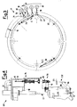
- the reference numeral 17 indicates schematically the mechanism for moving the filling section 14 of the machine 111 (this movement being obtained by trapezium-threaded screws, not shown), 12 indicates the feed pipes for the food products and for the electronic connections required for controlling the level 25 reached in the annular reservoir 13, 70 indicates overall the collection and drainage device for the sanitizer liquid, and 80 indicates a pneumatic cylinder which, by means of an arm 90 (welded by microfusion) and a support 232, moves the disc 23 on which the containers to be filled rest.
- the filling section 14 comprises an outer feed pipe 16 for the food product, an air vent pipe 15 and a filling cock 39 provided with a retention ring 28 and a gasket 29, these hermetically sealing the top of the false bottle 60.
- a drain pipe 18 for the food product is connected to the reservoir 13.
- the collection and drainage device 70 for the chemical liquid comprises the pinion 40 mounted on an idle pin 21 used for its fixing to the base 10 of the machine 111, while the false bottle 60 consists of two hollow concentric cylinders 32, 33 which slide one within the other by means of two springs 27 and support a disc 31.
- a piston 34 which is fixed to the cylinder 33 by two springs 35 and is hollow to enable the sanitizer liquid to emerge.
- Said liquid is fed into the filling section 14 via a valve 24, and is drained at the end of the sanitizing treatment from the cup-shaped chamber 26 which forms part of the cavity 37 of the cylinder 32 bounded by the lower end of the pipe 16 and the upper end of the piston 34.
- the cylinder 33 is fixed by a weld 36 to the swivel arm 19 which connects it to the pin 21.
- the described filling system uses an electronic control arrangement consisting of sensor devices, actuator devices and a suitable control program, so that the operating parameters can be freely chosen and varied within ranges predetermined by the user, using the keyboard of an electronic processor.
- the apparatus which implements the sanitizing method of the present invention operates substantially as follows: the treatment initiation command is given after the normal operating cycle of the filling system 11 has been interrupted and the containers are no longer present on the discs 23.
- the actuator cylinders 20 are provided with control microswitches providing a pneumatic rotation command which moves the cylinder 20 into its working position from its rest position. The rotation is fixed and is determined by the limit switches on the cylinders 20.
- the mover mechanism 17 slides the filling section 14 in the direction of the arrow D of Figure 5, together with the cock 39, which is pressed hermetically against the top of the false bottle 60 via the ring 28, the gasket 29 and the springs 27.
- the feed pipe is then lowered, via an aperture in the cock 39 and disc 31, into the cavity 37 within the cylinder 32, while the piston 34 adheres to the inner walls of the cylinder 32, supported by the springs 35.
- the pipe 16 is inserted into the cavity 37 in such a manner that between the top of the piston 34 and the lower end of the pipe 16 there is left an empty cup-shaped space 26.
- the next stage of the method comprises feeding the chemical sanitizer liquid through the valve 24 (positioned to the side of and above the cock 39 ), which is opened at the moment in which the piston 34 is made to slide within the cylinder 32 by means of the springs 35, in the direction of the arrow E of Figure 6, by the movement of the pneumatic cylinder 80 which, by means of the arm 90 and the support 232, urges the disc 23 into contact with the piston 34, with the result that the disc 31 of the false bottle 60 is squeezed against the cock 39.
- said movement of the cylinder 80 is the same movement which also occurs during the container filling cycles, when they are brought into contact with the cock 39 by the disc 23.
- the liquid inlet valve 24 On termination of the sanitizing method in question (its duration can be programmed by the user and depends on the type of food product used and the type of contamination produced), the liquid inlet valve 24 is closed, the mover mechanism 17 returns the filling section 14 to its rest position, such that the cock 39 moves in the direction of the arrow L of Figure 8 to withdraw from the disc 31 of the false bottle 60, and the cylinder 80 lowers to withdraw the support 232 and the disc 23 and release the piston 34 which, because of the fact that the springs 35 are released, is extracted from the cavity 37 of the cylinder 32. This latter movement causes the residues present in the cup 26 to be discharged to the outside along the cavity 55 of the piston 34, in the direction of the arrow M of Figure 8.
- This total drainage of the cup 26 makes the sanitizing treatment particularly efficient, because the complete washing of the parts subject to contamination by bacteria is supplemented by a second wash, determined by the velocity of the liquid leaving the cup 26 and entraining all the residues with it, to achieve a high level of purity of the entire system 11.
- the drainage cup 26 for the sanitizer liquid has a smaller outlet cross-section than the known art (liquid drainage currently takes place only at the level of the reservoir via the pipe 18), and hence the velocity of the outlet liquid is greater, with the result that it is easier to eliminate any incrustation formed in the pipes 15, 16 and in the reservoir 13.
- they include: a greater effectiveness of washing and of removal of incrustation, microbes and contaminants compared with the known art for equal pressures of the chemical liquid fed into the machine pipes; a smaller loss of contaminant chemical liquid compared with the known art, during sanitizing treatment; a shorter working cycle compared with the known art, for the same food product used; operator safety against undesirable splashing or leakage of liquid during the sanitizing treatment; compliance with current national and international regulations regarding the emission of contaminants and the presence of microbes, bacteria, impurities and contaminants within food products; facility for completely automating the sanitizing process, so that the variables concerned (activation, deactivation, duration, quantity and type of liquid) can be chosen and programmed by the user via a keyboard.
Abstract
Description
- This invention relates to a method for sanitizing filling machines and systems, in particular for food products, for the purpose of reducing the microbic load, and to the apparatus used for implementing this method.
- The machines used for filling bottles and cans with food products (wines, liqueurs, syrups, fruit juices, oil) are usually of the vacuum-operated type and are completely automated. A device creates the vacuum in the container into which the product is to be drawn after flowing from the main source to the machine reservoir which is mounted above the filling section. The liquid volume in the reservoir is controlled by a float or by suitable probes. The containers are lifted towards the filling cocks on discs operated by cams, and are made to adhere hermetically against the rubber rings of the cocks, the air present in them being gradually expelled via a vent pipe on applying the vacuum.
- In this type of machine the entire filling and reservoir section must be completely sanitized a number of times per day depending on the type of food product treated, in order to reduce the concentration of the microbes which are inevitably present in food products and which, at each filling, contaminate the walls of the reservoir and flow pipes.
- For this purpose it is known to use liquid chemical products which, when the machine operation is halted and the container filling cycle interrupted, are made to flow into the annular reservoir and from there to the interior of the feed pipes of the filling section as far as the cock, following the same path as the food products.
- After washing, the liquid is drained through a suitable pipe connected to the reservoir.
- The total duration of the treatment depends on the initial concentration of microbes and contaminant substances present at a certain moment in the system, and which as they accumulate at each filling cycle multiply the undesirable presence of bacteria within the food product.
- Furthermore, said duration depends on the degree of final microbe and bacteria concentration (in the sense of being evaluated after container filling) allowed by current national and international laws concerning food contamination.
- It would clearly be advantageous to reduce the total time of wash cycles required for sanitizing the machine and food products, so as to utilize to a maximum extent the productivity of the filling system by reducing halts during operation as much as possible.
- A further drawback of traditional sanitizing methods is that during treatment, liquid losses frequently occur through the pipes of the filling section and in particular through the cock, because of seal imperfections or undesired leakages from the drain pipe connected to the reservoir. This results in considerable operating costs and high concentrations of contaminating emissions.
- Finally, known methods do not completely solve the problem of incrustations left by the food products within the system. These tend to remain even after the wash cycle because the liquid drainage rate is insufficient to remove them, and because the pressure of the chemical product is maintained low (2-3 atmospheres) to limit danger in the case of leakage into the surrounding environment.
- An object of the present invention is to indicate a method for sanitizing filling machines and systems, in particular for food products, which overcomes the aforesaid drawbacks.
- A further object of the present invention is to carry out a sanitizing apparatus implementing said method.
- A further object of the present invention is to completely automate the method so that the user can program and/or vary all the main operating parameters (commencement and interruption of the wash cycle, duration, quantity and quality of the chemical product to be used, liquid pressure within the pipes, liquid drainage rate from the system).
- A further object of the present invention is to achieve an operating cost for said apparatus which is substantially less than in the known art, and further to achieve a lesser chemical contamination of the surrounding environment (compared with the known art) by the liquid used for the microbicide treatment.
- These objects are attained by a sanitizing method for filling machines and systems, in particular for food products, in accordance with claim 1, and a sanitizing apparatus implementing said method, in accordance with claim 2, to which reference should be made for brevity.
- Advantageously, the apparatus of the present invention comprises for the chemical sanitizer liquid at least one collection and drainage device, which is attached to a fixing pin at the base of the filling machine and is inserted (by the operation, at the moment the wash cycle starts, of two actuator cylinders mounted on the base and connected to a ring gear carrying said device) between each filling cock and the relative container support disc, to simulate a false bottle to be filled.
- The collection and drainage device for the sanitizer liquid comprises a hollow cylinder, into which there flows the chemical wash product, a retention disc arranged to hermetically seal the device when it comes into contact with the cock of the filling section, and a movable piston arranged to close the cylinder (and simultaneously open the inlet valve for the sanitizer liquid) during liquid circulation, and arranged to open the cylinder during liquid drainage from the system.
- The countercurrent entry of the liquid into the machine pipes and the drainage of the entire volume of chemical product, which takes place from a chamber of small cross-section (relative to the known art), this chamber collecting the contaminant scale and residual bacteria present in the pipes through which the food product flows, result in complete and reliable washing of the system in lesser time and using a quantity of chemical sanitizer product less than the known art.
- Further objects and advantages of the present invention will be apparent from the ensuing description and the accompanying drawings, which are provided by way of non-limiting example and in which:
- Figure 1 is a partial plan view of a filling system, in particular for food products, according to the present invention, shown in a first operating state;
- Figure 2 is a partially sectional side view of the filling machine of the present invention, shown in the operating state of Figure 1;
- Figure 3 is a partial plan view of the filling system of the present invention, shown in a second operating state;
- Figure 4 is a partly sectional side view of the filling machine of the present invention, shown in the operating state of Figure 3;
- Figure 5 is a partly sectional side view of the filling machine of the present invention, shown in a third operating state;
- Figure 6 is a partly sectional side view of the filling machine of the present invention, shown in a fourth operating state;
- Figure 7 is an enlarged view of a detail of Figure 6;
- Figure 8 is a partly sectional side view, enlarged relative to Figures 2, 4, 5 and 6, of the filling machine of the present invention, shown in a fifth operating state.
- The stated figures show in chronological order the various operating stages of a filling machine, in particular for food products, during the sanitizing treatment according to the present invention. Specifically, Figures 1 and 2 relate to a rest state immediately preceding the commencement of treatment. Figures 3 and 4 relate to a subsequent state in which the sanitizing treatment has commenced and the collection and drainage devices are aligned with the respective filling cocks. Figure 5 shows the next state, in which the filling sections have been lowered until the filling cocks adhere hermetically to the top of the collection and drainage devices. Figures 6 and 7 show the next stage in which the container support discs urge the pistons of the collection and drainage devices to close the device cylinders and open the inlet valves for the chemical sanitizer liquid. Finally, Figure 8 represents the final state with the sanitizing treatment completed, in which the filling cocks have been withdrawn from the collection and drainage devices and the device pistons have opened the cylinders and closed the chemical liquid inlet valves, to allow complete drainage of the bacterial residues and contaminating substances, which leave the bottom of the collection devices.
- In Figures 1, 2, 3, 4, 5 and 6, the
reference numeral 11 indicates overall the food product filling system, and 111 indicates one of the filling machines forming part of thesystem 11. The reference numerals given hereinafter together with the description of operation of the apparatus implementing the method of the present invention relate to one of thefilling machines 111 of thefilling system 11 per reasons of simplicity and clarity of description. - It is however clear that the description is equally valid for all the
machines 111 forming part of thesystem 11. In Figures 1 and 3, thereference numeral 10 indicates the base of thefilling machine ring gear 30 connected to a plurality of collection anddrainage devices 70 for the chemical sanitizer liquid of thesystem 11. Specifically these figures show four collection anddrainage devices 70 for simplicity and by way of non-limiting example. These are however provided in the same number as the number offilling machines 111 forming part of thesystem 11. - Each
device 70 comprises apinion 40 adjacent to thering gear 30, apin 21 for its fixing to thebase 10, aswivel arm 19 and a liquid collection and drainage means in the form of a container to simulate the bottle to be filled during the sanitizing of thesystem 11. Hereinafter, said means 60 will be known as the false bottle. In Figures 2, 4, 5, 6, 7 and 8, thereference numeral 17 indicates schematically the mechanism for moving thefilling section 14 of the machine 111 (this movement being obtained by trapezium-threaded screws, not shown), 12 indicates the feed pipes for the food products and for the electronic connections required for controlling thelevel 25 reached in theannular reservoir support 232, moves thedisc 23 on which the containers to be filled rest. Thefilling section 14 comprises anouter feed pipe 16 for the food product, anair vent pipe 15 and afilling cock 39 provided with aretention ring 28 and agasket 29, these hermetically sealing the top of thefalse bottle 60. Adrain pipe 18 for the food product is connected to thereservoir 13. The collection anddrainage device 70 for the chemical liquid comprises thepinion 40 mounted on anidle pin 21 used for its fixing to thebase 10 of themachine 111, while thefalse bottle 60 consists of two hollowconcentric cylinders springs 27 and support adisc 31. - Within the
cylinder 32 there can slide apiston 34, which is fixed to thecylinder 33 by twosprings 35 and is hollow to enable the sanitizer liquid to emerge. Said liquid is fed into thefilling section 14 via avalve 24, and is drained at the end of the sanitizing treatment from the cup-shaped chamber 26 which forms part of thecavity 37 of thecylinder 32 bounded by the lower end of thepipe 16 and the upper end of thepiston 34. Thecylinder 33 is fixed by aweld 36 to theswivel arm 19 which connects it to thepin 21. Finally, the described filling system uses an electronic control arrangement consisting of sensor devices, actuator devices and a suitable control program, so that the operating parameters can be freely chosen and varied within ranges predetermined by the user, using the keyboard of an electronic processor. - The apparatus which implements the sanitizing method of the present invention operates substantially as follows: the treatment initiation command is given after the normal operating cycle of the
filling system 11 has been interrupted and the containers are no longer present on thediscs 23. - In addition the
discs 23 have been withdrawn from thecock 39 of thefilling section 14, and themover mechanism 17 for thesection 14 has been brought into an upper limiting position in which the screw thread is totally elongated in the direction of the arrow A of Figure 2 and thecocks 39 are totally raised. Theactuator cylinders 20 are provided with control microswitches providing a pneumatic rotation command which moves thecylinder 20 into its working position from its rest position. The rotation is fixed and is determined by the limit switches on thecylinders 20. As thecylinders 20 communicate their movement to thering gear 30, this is compelled to rotate in the direction of the arrows C of Figure 3 to transmit its rotation to thepinions 40, which open theswivel arms 19 in the direction of the arrow B of Figure 3, after which they withdraw thefalse bottle 60 from thepin 21 fixing it to thebase 10, so that it becomes coaxial with thecock 39. - At this point, by means of an electronic position control, the
mover mechanism 17 slides thefilling section 14 in the direction of the arrow D of Figure 5, together with thecock 39, which is pressed hermetically against the top of thefalse bottle 60 via thering 28, thegasket 29 and thesprings 27. The feed pipe is then lowered, via an aperture in thecock 39 anddisc 31, into thecavity 37 within thecylinder 32, while thepiston 34 adheres to the inner walls of thecylinder 32, supported by thesprings 35. Thepipe 16 is inserted into thecavity 37 in such a manner that between the top of thepiston 34 and the lower end of thepipe 16 there is left an empty cup-shaped space 26. - The next stage of the method comprises feeding the chemical sanitizer liquid through the valve 24 (positioned to the side of and above the cock 39 ), which is opened at the moment in which the
piston 34 is made to slide within thecylinder 32 by means of thesprings 35, in the direction of the arrow E of Figure 6, by the movement of thepneumatic cylinder 80 which, by means of thearm 90 and thesupport 232, urges thedisc 23 into contact with thepiston 34, with the result that thedisc 31 of thefalse bottle 60 is squeezed against thecock 39. It should be noted that said movement of thecylinder 80 is the same movement which also occurs during the container filling cycles, when they are brought into contact with thecock 39 by thedisc 23. This justifies the name of "false bottle" given to the collection and drainage means 60 for the liquid (as the sanitizing treatment according to the invention simulates to some extent a traditional filling of the containers), and results in wash cycle times less than known sanitizing methods, for the same food product used. The sanitizer-liquid undergoes the path indicated by the arrows F in Figure 7, entering thecavity 37 of thecylinder 32 as far as thecup 26; from here it rises along thepipe 16 to reach the annular reservoir 13 (following the directions of the arrows G and H of Figure 7), to result in careful washing together with microbicide and anti-contamination treatment of all those parts of themachine 111 subject to contamination by the bacteria present in the food products fed into the containers. At the same time thevent pipe 15 leads the air accumulated in thecup 26 to the outside, in the direction of the arrow N of Figure 7. - On termination of the sanitizing method in question (its duration can be programmed by the user and depends on the type of food product used and the type of contamination produced), the
liquid inlet valve 24 is closed, themover mechanism 17 returns the fillingsection 14 to its rest position, such that thecock 39 moves in the direction of the arrow L of Figure 8 to withdraw from thedisc 31 of thefalse bottle 60, and thecylinder 80 lowers to withdraw thesupport 232 and thedisc 23 and release thepiston 34 which, because of the fact that thesprings 35 are released, is extracted from thecavity 37 of thecylinder 32. This latter movement causes the residues present in thecup 26 to be discharged to the outside along thecavity 55 of thepiston 34, in the direction of the arrow M of Figure 8. - This total drainage of the
cup 26 makes the sanitizing treatment particularly efficient, because the complete washing of the parts subject to contamination by bacteria is supplemented by a second wash, determined by the velocity of the liquid leaving thecup 26 and entraining all the residues with it, to achieve a high level of purity of theentire system 11. - In this respect, the
drainage cup 26 for the sanitizer liquid has a smaller outlet cross-section than the known art (liquid drainage currently takes place only at the level of the reservoir via the pipe 18), and hence the velocity of the outlet liquid is greater, with the result that it is easier to eliminate any incrustation formed in thepipes reservoir 13. - Moreover, as there is a lesser quantity of chemical liquid in circulation within the interior of the
system 11 compared with known methods, there is a lesser possibility of undesirable liquid leakages and losses, with the consequent advantage of a reduction in contamination by relatively toxic chemical substances. - From the aforegoing description the characteristics of the sanitizing method and apparatus for filling machines and systems according to the present invention are apparent, as are the resultant advantages.
- Specifically, they include: a greater effectiveness of washing and of removal of incrustation, microbes and contaminants compared with the known art for equal pressures of the chemical liquid fed into the machine pipes; a smaller loss of contaminant chemical liquid compared with the known art, during sanitizing treatment; a shorter working cycle compared with the known art, for the same food product used; operator safety against undesirable splashing or leakage of liquid during the sanitizing treatment; compliance with current national and international regulations regarding the emission of contaminants and the presence of microbes, bacteria, impurities and contaminants within food products; facility for completely automating the sanitizing process, so that the variables concerned (activation, deactivation, duration, quantity and type of liquid) can be chosen and programmed by the user via a keyboard.
- Finally, it is apparent that numerous further modifications can be made to the sanitizing method and apparatus of the present invention, without leaving the principles of novelty contained in the inventive idea, it also being apparent that in the practical implementation of the invention, the materials, the shapes and the dimensions of the illustrated details can be chosen at will according to requirements, and can be replaced by others technically equivalent.
Claims (10)
- A sanitizing method for filling machines (111) and systems (11), in particular for food products, characterised by comprising the following stages:- interrupting the filling cycle of the system (11) and removing the containers from their support discs (23);- withdrawing the support discs (23) from the cocks (39) of the filling sections (14) and simultaneously raising (A) the filling sections (14) and hence the cocks (39) by means of at least one mover mechanism (17), which is brought from a first rest position to a first working position;- rotating at least one actuator means (20) fixed to the base (10) of the filling system (11), to assume a second working position in which it communicates its rotation (C) to at least one ring gear (30) which itself transmits its rotation to the pinions (40) of a plurality of collection and drainage devices (70) for the sanitizer liquid, to cause the opening (B) of swivel arms (19), each of which carries a liquid collection and drainage means (60), such that said collection and drainage means (60) become coaxial with said cocks (39);- lowering (D) the filling sections (14) and cocks (39), by means of said mover mechanism (17) in such a manner as to press said cocks (39) hermetically against the collection and drainage means (60) for the sanitizer liquid;- via a plurality of apertures in the cocks (39) and in the collection and drainage means (60), inserting food product feed pipes (16) into first cavities (37) within said collection and drainage means (60);- feeding (F) chemical sanitizer liquid into the filling system (11) via at least one valve (24), which is opened the moment in which a plurality of pistons (34) are made to slide within the relative first cylinders (32), contained within said collection and drainage means (60), by the movement (E) of second cylinders (80), which urge each support disc (23) into contact with one of said pistons (34), said liquid flowing through said cavities (37) to be collected (F) in regions (26) between said feed pipes (16) and said pistons (34), to pass within said feed pipes (16) and finally reach a plurality of reservoirs (13) provided with at least one drain pipe (18) and used to contain the food products during their filling, the air which in the meanwhile has accumulated within said regions (26) being conveyed (N) to the outside of the system (11) by means of a plurality of vent pipes (15);- closing said valve (24) by operating said second cylinders (80), which lower said support discs (23) to release said pistons (34) from said first cylinders (32), such that the pistons (34) are extracted from said first cavities (37), with simultaneous raising (L) of the filling sections (14) and cocks (39), by means of said mover mechanism (17), such that said cocks (39) are withdrawn from said collection and drainage means (60);- draining (M) residues, scale, incrustation remains, contaminant substances and bacteria which have collected in the regions (26) of said collection and drainage means (60), and are discharged to the outside through said second cavities (55) provided within said pistons (34).
- A sanitizing apparatus for filling machines (111) and systems (11), in particular for food products, which implements the method claimed in claim 1, comprising a plurality of filling sections (14) for containers positioned on support discs (23), said sections comprising at least one cock (39) and being fed by food product feed means (12) and operated by at least one mover mechanism (17), said support discs (23) being operated by pneumatic actuator elements (80, 90, 232) which operate synchronously with said mover mechanism (17), characterised in that said actuator means (20), which is fixed to the base (10) of the filling system, is a pneumatic cylinder which on receiving commands from limit microswitches moves (C) into a working position, transmitting motion to said ring gear (30) and to said collection and drainage devices (70) for the sanitizer liquid.
- A sanitizing apparatus for filling machines (111) and systems (11), in particular for food products, as claimed in claim 2, characterised in that each collection and drainage device (70) for the sanitizing liquid comprises at least one pinion (40) operated by said ring gear (30), at least one pin (21) for fixing said device (70) to the base (10) of the system (11), and at least one swivel arm (19) fixed to the body of said pin (21) and carrying, at one end, at least one collection and drainage means (60) for the sanitizer liquid.
- A sanitizing apparatus for filling machines (111) and systems (11), in particular for food products, as claimed in claim 3, characterised in that said collection and drainage means (60) for the sanitizer liquid comprises a hollow first cylinder (33), a hollow second cylinder (32) internal to said first cylinder (33), and a piston (34) which can slide within a first cavity (37) internal to said cylinders (32, 33) and is connected to said first cylinder (33) by at least one spring (35), said first cylinder (33) being also connected to at least one disc (31) by means of at least one spring (27), said piston (34) comprising at least one second cavity (5) in its interior.
- A sanitizing apparatus for filling machines (111) and systems (11), in particular for food products, as claimed in claim 3, characterised in that said collection and drainage means (60) is welded to said swivel arm (19).
- A sanitizing apparatus for filling machines (111) and systems (11), in particular for food products, as claimed in claim 2, characterised in that said cock (39) comprises at least one seal ring (28) and at least one gasket (29) which are arranged to hermetically seal the cock (39) against said collection and drainage means (60) for the sanitizer liquid.
- A sanitizing apparatus for filling machines (111) and systems (11), in particular for food products, as claimed in claim 4, characterised in that said first cavity (37) can be partly engaged by a plurality of pipes (15, 16) for feeding sanitizer liquid to the system (11) and for venting air during the sanitizing treatment, so that a region (26) of said first cavity (37) is left free, into which the sanitizer liquid flows to then rise through said feed pipe (16) and from which the liquid and residues, scale, incrustation remains, bacteria and contaminant substances which flow into said second cavity (55) of said piston (34) are drained off, when this latter is extracted from said first cavity (37).
- A sanitizing apparatus for filling machines (111) and systems (11), in particular for food products, as claimed in claim 4, characterised in that said filling section (14) comprises at least one valve (24), through which the sanitzer liquid is fed (F) into the system (11) at the moment in which said piston (34) is inserted into said first cavity (37), said valve (24) being closed when the piston (34) is extracted from said first cavity (37).
- A sanitizing apparatus for filling machines (111) and systems (11), in particular for food products, as claimed in claim 2, characterised in that the operating parameters of the system (11) (activation, deactivation, duration of the sanitizing treatment, quantity and type of sanitizer liquid) can be chosen and programmed by the user via a keyboard, by virtue of the presence of a plurality of sensor devices and actuators of electronic type controlled by an application program executed in an electronic processor.
- A sanitizing apparatus for filling machines (111) and systems (11), in particular for food products, as claimed in claim 2, characterised by complying with current national and international regulations regarding the emission of contaminant substances and the contamination of the food products by organic residues, bacteria, microbes, scale and incrustation residues.
Applications Claiming Priority (2)
| Application Number | Priority Date | Filing Date | Title |
|---|---|---|---|
| IT96MI000059A IT1281670B1 (en) | 1996-01-16 | 1996-01-16 | SANITIZATION METHOD AND APPARATUS FOR FILLING MACHINES AND SYSTEMS, PARTICULARLY FOR FOOD PRODUCTS |
| ITMI960059 | 1996-01-16 |
Publications (3)
| Publication Number | Publication Date |
|---|---|
| EP0785134A2 true EP0785134A2 (en) | 1997-07-23 |
| EP0785134A3 EP0785134A3 (en) | 1997-12-10 |
| EP0785134B1 EP0785134B1 (en) | 2001-12-05 |
Family
ID=11372914
Family Applications (1)
| Application Number | Title | Priority Date | Filing Date |
|---|---|---|---|
| EP96202989A Expired - Lifetime EP0785134B1 (en) | 1996-01-16 | 1996-10-26 | Method and apparatus for sanitizing filling machines and systems, particularly for food products |
Country Status (5)
| Country | Link |
|---|---|
| EP (1) | EP0785134B1 (en) |
| AT (1) | ATE210047T1 (en) |
| DE (1) | DE69617620T2 (en) |
| ES (1) | ES2167514T3 (en) |
| IT (1) | IT1281670B1 (en) |
Cited By (14)
| Publication number | Priority date | Publication date | Assignee | Title |
|---|---|---|---|---|
| DE19808236A1 (en) * | 1998-02-27 | 1999-09-02 | Tetra Laval Holdings & Finance | Device for ventilating packages under low-germ conditions |
| EP1195325A1 (en) * | 2000-10-05 | 2002-04-10 | Shikoku Kakoki Co., Ltd. | Cleaning device for filling nozzles |
| ES2199009A1 (en) * | 2001-02-05 | 2004-02-01 | Danone Sa | Procedure and device for the sterilization of food disposal dosing devices and other. (Machine-translation by Google Translate, not legally binding) |
| ES2216666A1 (en) * | 2002-01-30 | 2004-10-16 | Irundin, S.L. | Bottle filler nozzle rinser has support with lower threaded section and regulating nuts for fork connected to rinsing vessel |
| EP1577258A1 (en) * | 2004-03-19 | 2005-09-21 | Servizi Tecnici Avanzati S.r.l. | Filling head and cleaning apparatus therefor |
| EP2103564A1 (en) * | 2008-03-17 | 2009-09-23 | Gallardo Ingenieria Del Embotellado, S.L. | Cleaning equipment for a bottle filling machine |
| EP2110359A1 (en) * | 2008-04-15 | 2009-10-21 | RONCHI MARIO S.p A. | Automatic apparatus for flushing operating machines and machine equipped with said apparatus |
| WO2009012011A3 (en) * | 2007-07-13 | 2009-11-12 | The Coca-Cola Company | Clean in place system for beverage dispensers |
| WO2009152979A1 (en) * | 2008-06-17 | 2009-12-23 | Bernd Hansen | Device for producing and filling containers |
| ITPD20090116A1 (en) * | 2009-04-30 | 2010-11-01 | Gruppo Bertolaso Spa | FILLING MACHINE AND SANITIZATION METHOD OF THIS FILLING MACHINE |
| ITTO20090531A1 (en) * | 2009-07-16 | 2011-01-17 | Gai S P A | DEVICE FOR THE STERILIZATION OF FILLING MACHINES AND FILLING MACHINE PROVIDED WITH THIS DEVICE |
| DE102010027623A1 (en) | 2010-07-19 | 2012-01-19 | Krones Aktiengesellschaft | Filling device for containers with cleaning system |
| WO2013026523A3 (en) * | 2011-08-23 | 2013-06-27 | Khs Gmbh | Filling machine and method for controlling a filling machine |
| WO2021213607A1 (en) | 2020-04-20 | 2021-10-28 | Sidel Participations | Filling device with automatic dummy bottle and method for cleaning the filling device |
Families Citing this family (1)
| Publication number | Priority date | Publication date | Assignee | Title |
|---|---|---|---|---|
| DE102017102852A1 (en) | 2017-02-13 | 2018-08-16 | Krones Ag | Device for filling a container with a filling product |
Family Cites Families (3)
| Publication number | Priority date | Publication date | Assignee | Title |
|---|---|---|---|---|
| US4024896A (en) * | 1975-05-13 | 1977-05-24 | Shibuya Kogyo Company, Ltd. | Washing device for rotary filling machine |
| DE3927402A1 (en) * | 1989-08-19 | 1991-02-21 | Holstein & Kappert Maschf | Cleaning bottle filling machine - involves mechanism to clean filler valves by applying liq. |
| DE4344614A1 (en) * | 1993-12-24 | 1995-06-29 | Ortmann & Herbst Masch Gmbh | Beverage filling machine with CIP cleaning cups |
-
1996
- 1996-01-16 IT IT96MI000059A patent/IT1281670B1/en active IP Right Grant
- 1996-10-26 AT AT96202989T patent/ATE210047T1/en not_active IP Right Cessation
- 1996-10-26 DE DE69617620T patent/DE69617620T2/en not_active Expired - Fee Related
- 1996-10-26 ES ES96202989T patent/ES2167514T3/en not_active Expired - Lifetime
- 1996-10-26 EP EP96202989A patent/EP0785134B1/en not_active Expired - Lifetime
Non-Patent Citations (1)
| Title |
|---|
| None |
Cited By (28)
| Publication number | Priority date | Publication date | Assignee | Title |
|---|---|---|---|---|
| US6105634A (en) * | 1998-02-27 | 2000-08-22 | Tetra Laval Holdings & Finance S.A. | Device for filling packages under low germ level conditions |
| DE19808236A1 (en) * | 1998-02-27 | 1999-09-02 | Tetra Laval Holdings & Finance | Device for ventilating packages under low-germ conditions |
| EP1195325A1 (en) * | 2000-10-05 | 2002-04-10 | Shikoku Kakoki Co., Ltd. | Cleaning device for filling nozzles |
| US6401771B1 (en) | 2000-10-05 | 2002-06-11 | Shikoku Kakoki Co., Ltd | Cleaning device for filling nozzles |
| ES2199009A1 (en) * | 2001-02-05 | 2004-02-01 | Danone Sa | Procedure and device for the sterilization of food disposal dosing devices and other. (Machine-translation by Google Translate, not legally binding) |
| ES2216666A1 (en) * | 2002-01-30 | 2004-10-16 | Irundin, S.L. | Bottle filler nozzle rinser has support with lower threaded section and regulating nuts for fork connected to rinsing vessel |
| EP1577258A1 (en) * | 2004-03-19 | 2005-09-21 | Servizi Tecnici Avanzati S.r.l. | Filling head and cleaning apparatus therefor |
| RU2468986C2 (en) * | 2007-07-13 | 2012-12-10 | Дзе Кока-Кола Компани | Drink dispenser in-place cleaner |
| US8678239B2 (en) | 2007-07-13 | 2014-03-25 | The Coca-Cola Company | Clean in place system for beverage dispensers |
| WO2009012011A3 (en) * | 2007-07-13 | 2009-11-12 | The Coca-Cola Company | Clean in place system for beverage dispensers |
| AU2008276391B2 (en) * | 2007-07-13 | 2013-07-25 | The Coca-Cola Company | Clean in place system for beverage dispensers |
| EP2192078A1 (en) * | 2007-07-13 | 2010-06-02 | The Coca-Cola Company | Clean in place system for beverage dispensers |
| EP2103564A1 (en) * | 2008-03-17 | 2009-09-23 | Gallardo Ingenieria Del Embotellado, S.L. | Cleaning equipment for a bottle filling machine |
| EP2110359A1 (en) * | 2008-04-15 | 2009-10-21 | RONCHI MARIO S.p A. | Automatic apparatus for flushing operating machines and machine equipped with said apparatus |
| CN101559912B (en) * | 2008-04-15 | 2013-08-07 | 龙基马里奥股份公司 | Automatic apparatus for flushing operating machines and machines equipped with the said apparatus |
| AU2009259653B2 (en) * | 2008-06-17 | 2013-09-05 | Bernd Hansen | Device for producing and filling containers |
| JP2011524840A (en) * | 2008-06-17 | 2011-09-08 | ハンゼン,ベルント | Equipment for forming and filling containers |
| RU2503595C2 (en) * | 2008-06-17 | 2014-01-10 | Бернд ХАНСЕН | Device for manufacturing and filling containers |
| US8480390B2 (en) | 2008-06-17 | 2013-07-09 | Bernd Hansen | Device for producing and filling containers |
| WO2009152979A1 (en) * | 2008-06-17 | 2009-12-23 | Bernd Hansen | Device for producing and filling containers |
| EP2246291A1 (en) * | 2009-04-30 | 2010-11-03 | Gruppo Bertolaso S.p.A. | Filling machine and method for sanitising said filling machine |
| ITPD20090116A1 (en) * | 2009-04-30 | 2010-11-01 | Gruppo Bertolaso Spa | FILLING MACHINE AND SANITIZATION METHOD OF THIS FILLING MACHINE |
| ITTO20090531A1 (en) * | 2009-07-16 | 2011-01-17 | Gai S P A | DEVICE FOR THE STERILIZATION OF FILLING MACHINES AND FILLING MACHINE PROVIDED WITH THIS DEVICE |
| DE102010027623A1 (en) | 2010-07-19 | 2012-01-19 | Krones Aktiengesellschaft | Filling device for containers with cleaning system |
| EP2409947A2 (en) | 2010-07-19 | 2012-01-25 | Krones AG | Filling device for containers with cleaning system |
| WO2013026523A3 (en) * | 2011-08-23 | 2013-06-27 | Khs Gmbh | Filling machine and method for controlling a filling machine |
| US9284173B2 (en) | 2011-08-23 | 2016-03-15 | Khs Gmbh | Filling machine and method for controlling a filling machine |
| WO2021213607A1 (en) | 2020-04-20 | 2021-10-28 | Sidel Participations | Filling device with automatic dummy bottle and method for cleaning the filling device |
Also Published As
| Publication number | Publication date |
|---|---|
| EP0785134A3 (en) | 1997-12-10 |
| ITMI960059A0 (en) | 1996-01-16 |
| IT1281670B1 (en) | 1998-02-26 |
| EP0785134B1 (en) | 2001-12-05 |
| DE69617620T2 (en) | 2002-08-08 |
| ES2167514T3 (en) | 2002-05-16 |
| DE69617620D1 (en) | 2002-01-17 |
| ITMI960059A1 (en) | 1997-07-16 |
| ATE210047T1 (en) | 2001-12-15 |
Similar Documents
| Publication | Publication Date | Title |
|---|---|---|
| EP0785134B1 (en) | Method and apparatus for sanitizing filling machines and systems, particularly for food products | |
| EP0001464B1 (en) | A method and an arrangement for the cleaning of a filler pipe in a packing machine | |
| EP0965524A1 (en) | Aseptic container filling assembly | |
| EP0962420A2 (en) | Rotary filling machine for filling containers with liquids | |
| EP0955240A1 (en) | High speed aseptic filling machine | |
| NZ198037A (en) | Double seat valve with leakage check | |
| US6330780B1 (en) | Apparatus and method for filling | |
| CN101541443B (en) | Injection of purge gas to beverage containers | |
| US3513024A (en) | Method for cleaning automatic liquid filling machine valves | |
| JP2604540B2 (en) | Carton filling equipment | |
| WO2009004500A1 (en) | Filling valve for a filling machine | |
| US5548944A (en) | Vacuum operated processing station having a liquid separating system | |
| EP0996584B1 (en) | Machine and method for filling containers, in particular bottles | |
| JPS6220119B2 (en) | ||
| EP2246291B1 (en) | Filling machine and method for sanitising said filling machine | |
| US5009339A (en) | Method of and an apparatus for venting a filling plant | |
| AU699264B2 (en) | Automated product draining method for a packaging machine | |
| EP1457457A2 (en) | Filling head | |
| EP2444364B1 (en) | Isobaric machine for filling contaniers with liquids | |
| JPH0930597A (en) | Method and device for cleaning food changing valve | |
| EP0453823A2 (en) | Improvements in a machine for the preparation and filling of drums for fluid products | |
| NL9300302A (en) | Method for inoculating a liquid and inoculation vessel and device for applying the method. | |
| MXPA97002391A (en) | Method for automatic draining of a product for a packaging machine | |
| CN216955320U (en) | Automatic sampling device for barreled waste | |
| EP3822224A1 (en) | Filling machine and method for filling containers with a pourable product |
Legal Events
| Date | Code | Title | Description |
|---|---|---|---|
| PUAI | Public reference made under article 153(3) epc to a published international application that has entered the european phase |
Free format text: ORIGINAL CODE: 0009012 |
|
| AK | Designated contracting states |
Kind code of ref document: A2 Designated state(s): AT BE CH DE ES FR GB LI NL PT |
|
| PUAL | Search report despatched |
Free format text: ORIGINAL CODE: 0009013 |
|
| AK | Designated contracting states |
Kind code of ref document: A3 Designated state(s): AT BE CH DE ES FR GB LI NL PT |
|
| 17P | Request for examination filed |
Effective date: 19980516 |
|
| 17Q | First examination report despatched |
Effective date: 19991119 |
|
| GRAG | Despatch of communication of intention to grant |
Free format text: ORIGINAL CODE: EPIDOS AGRA |
|
| GRAG | Despatch of communication of intention to grant |
Free format text: ORIGINAL CODE: EPIDOS AGRA |
|
| GRAH | Despatch of communication of intention to grant a patent |
Free format text: ORIGINAL CODE: EPIDOS IGRA |
|
| GRAH | Despatch of communication of intention to grant a patent |
Free format text: ORIGINAL CODE: EPIDOS IGRA |
|
| GRAA | (expected) grant |
Free format text: ORIGINAL CODE: 0009210 |
|
| AK | Designated contracting states |
Kind code of ref document: B1 Designated state(s): AT BE CH DE ES FR GB LI NL PT |
|
| PG25 | Lapsed in a contracting state [announced via postgrant information from national office to epo] |
Ref country code: NL Free format text: LAPSE BECAUSE OF FAILURE TO SUBMIT A TRANSLATION OF THE DESCRIPTION OR TO PAY THE FEE WITHIN THE PRESCRIBED TIME-LIMIT Effective date: 20011205 Ref country code: BE Free format text: LAPSE BECAUSE OF FAILURE TO SUBMIT A TRANSLATION OF THE DESCRIPTION OR TO PAY THE FEE WITHIN THE PRESCRIBED TIME-LIMIT Effective date: 20011205 |
|
| REF | Corresponds to: |
Ref document number: 210047 Country of ref document: AT Date of ref document: 20011215 Kind code of ref document: T |
|
| REG | Reference to a national code |
Ref country code: CH Ref legal event code: EP |
|
| REG | Reference to a national code |
Ref country code: GB Ref legal event code: IF02 |
|
| REF | Corresponds to: |
Ref document number: 69617620 Country of ref document: DE Date of ref document: 20020117 |
|
| REG | Reference to a national code |
Ref country code: CH Ref legal event code: NV Representative=s name: AMMANN PATENTANWAELTE AG BERN |
|
| PG25 | Lapsed in a contracting state [announced via postgrant information from national office to epo] |
Ref country code: PT Free format text: LAPSE BECAUSE OF FAILURE TO SUBMIT A TRANSLATION OF THE DESCRIPTION OR TO PAY THE FEE WITHIN THE PRESCRIBED TIME-LIMIT Effective date: 20020305 |
|
| NLV1 | Nl: lapsed or annulled due to failure to fulfill the requirements of art. 29p and 29m of the patents act | ||
| REG | Reference to a national code |
Ref country code: ES Ref legal event code: FG2A Ref document number: 2167514 Country of ref document: ES Kind code of ref document: T3 |
|
| PGFP | Annual fee paid to national office [announced via postgrant information from national office to epo] |
Ref country code: FR Payment date: 20021008 Year of fee payment: 7 |
|
| PGFP | Annual fee paid to national office [announced via postgrant information from national office to epo] |
Ref country code: AT Payment date: 20021011 Year of fee payment: 7 |
|
| PLBE | No opposition filed within time limit |
Free format text: ORIGINAL CODE: 0009261 |
|
| STAA | Information on the status of an ep patent application or granted ep patent |
Free format text: STATUS: NO OPPOSITION FILED WITHIN TIME LIMIT |
|
| PG25 | Lapsed in a contracting state [announced via postgrant information from national office to epo] |
Ref country code: GB Free format text: LAPSE BECAUSE OF NON-PAYMENT OF DUE FEES Effective date: 20021026 |
|
| PGFP | Annual fee paid to national office [announced via postgrant information from national office to epo] |
Ref country code: ES Payment date: 20021031 Year of fee payment: 7 Ref country code: DE Payment date: 20021031 Year of fee payment: 7 |
|
| PGFP | Annual fee paid to national office [announced via postgrant information from national office to epo] |
Ref country code: CH Payment date: 20021101 Year of fee payment: 7 |
|
| 26N | No opposition filed | ||
| GBPC | Gb: european patent ceased through non-payment of renewal fee | ||
| PG25 | Lapsed in a contracting state [announced via postgrant information from national office to epo] |
Ref country code: AT Free format text: LAPSE BECAUSE OF NON-PAYMENT OF DUE FEES Effective date: 20031026 |
|
| PG25 | Lapsed in a contracting state [announced via postgrant information from national office to epo] |
Ref country code: ES Free format text: LAPSE BECAUSE OF NON-PAYMENT OF DUE FEES Effective date: 20031027 |
|
| PG25 | Lapsed in a contracting state [announced via postgrant information from national office to epo] |
Ref country code: LI Free format text: LAPSE BECAUSE OF NON-PAYMENT OF DUE FEES Effective date: 20031031 Ref country code: CH Free format text: LAPSE BECAUSE OF NON-PAYMENT OF DUE FEES Effective date: 20031031 |
|
| PG25 | Lapsed in a contracting state [announced via postgrant information from national office to epo] |
Ref country code: DE Free format text: LAPSE BECAUSE OF NON-PAYMENT OF DUE FEES Effective date: 20040501 |
|
| REG | Reference to a national code |
Ref country code: CH Ref legal event code: PL |
|
| PG25 | Lapsed in a contracting state [announced via postgrant information from national office to epo] |
Ref country code: FR Free format text: LAPSE BECAUSE OF NON-PAYMENT OF DUE FEES Effective date: 20040630 |
|
| REG | Reference to a national code |
Ref country code: FR Ref legal event code: ST |
|
| REG | Reference to a national code |
Ref country code: ES Ref legal event code: FD2A Effective date: 20031027 |