RU2503545C1 - Thermal printer and method of its operation - Google Patents
Thermal printer and method of its operation Download PDFInfo
- Publication number
- RU2503545C1 RU2503545C1 RU2012117766/12A RU2012117766A RU2503545C1 RU 2503545 C1 RU2503545 C1 RU 2503545C1 RU 2012117766/12 A RU2012117766/12 A RU 2012117766/12A RU 2012117766 A RU2012117766 A RU 2012117766A RU 2503545 C1 RU2503545 C1 RU 2503545C1
- Authority
- RU
- Russia
- Prior art keywords
- period
- activation
- thermal head
- activating
- recording medium
- Prior art date
Links
- 238000000034 method Methods 0.000 title claims abstract description 9
- 230000004913 activation Effects 0.000 claims abstract description 46
- 238000010438 heat treatment Methods 0.000 claims abstract description 46
- 230000003213 activating effect Effects 0.000 claims abstract description 26
- 230000009849 deactivation Effects 0.000 claims abstract description 10
- 230000008859 change Effects 0.000 claims description 10
- 230000001276 controlling effect Effects 0.000 claims 1
- 230000001105 regulatory effect Effects 0.000 claims 1
- 230000015572 biosynthetic process Effects 0.000 abstract description 6
- 230000000694 effects Effects 0.000 abstract description 2
- 239000000126 substance Substances 0.000 abstract 1
- 230000007246 mechanism Effects 0.000 description 4
- 230000007423 decrease Effects 0.000 description 3
- 230000006870 function Effects 0.000 description 3
- 238000012546 transfer Methods 0.000 description 3
- 238000009500 colour coating Methods 0.000 description 2
- 238000004891 communication Methods 0.000 description 2
- 230000003247 decreasing effect Effects 0.000 description 2
- 238000010586 diagram Methods 0.000 description 2
- 238000013021 overheating Methods 0.000 description 2
- 238000009825 accumulation Methods 0.000 description 1
- 238000001816 cooling Methods 0.000 description 1
- 238000005338 heat storage Methods 0.000 description 1
- 239000011159 matrix material Substances 0.000 description 1
- 239000000155 melt Substances 0.000 description 1
- 238000002844 melting Methods 0.000 description 1
- 230000008018 melting Effects 0.000 description 1
- 238000012544 monitoring process Methods 0.000 description 1
- 239000011148 porous material Substances 0.000 description 1
- 230000009467 reduction Effects 0.000 description 1
- 230000001360 synchronised effect Effects 0.000 description 1
Images
Classifications
-
- B—PERFORMING OPERATIONS; TRANSPORTING
- B41—PRINTING; LINING MACHINES; TYPEWRITERS; STAMPS
- B41J—TYPEWRITERS; SELECTIVE PRINTING MECHANISMS, i.e. MECHANISMS PRINTING OTHERWISE THAN FROM A FORME; CORRECTION OF TYPOGRAPHICAL ERRORS
- B41J2/00—Typewriters or selective printing mechanisms characterised by the printing or marking process for which they are designed
- B41J2/315—Typewriters or selective printing mechanisms characterised by the printing or marking process for which they are designed characterised by selective application of heat to a heat sensitive printing or impression-transfer material
- B41J2/32—Typewriters or selective printing mechanisms characterised by the printing or marking process for which they are designed characterised by selective application of heat to a heat sensitive printing or impression-transfer material using thermal heads
- B41J2/35—Typewriters or selective printing mechanisms characterised by the printing or marking process for which they are designed characterised by selective application of heat to a heat sensitive printing or impression-transfer material using thermal heads providing current or voltage to the thermal head
- B41J2/355—Control circuits for heating-element selection
Landscapes
- Electronic Switches (AREA)
Abstract
Description
Область техникиTechnical field
Настоящее изобретение относится к термографическому печатающему устройству, которое формирует печатные точки на бумаге для записи с помощью активизации и нагревания нагревательных элементов термопечатающей головки, и к способу управления им.The present invention relates to a thermographic printing device that forms printing points on recording paper by activating and heating the heating elements of the thermal head, and to a method for controlling them.
Уровень техникиState of the art
Термографические печатающие устройства, которые перемещают термобумагу или другую бумагу для записи между термопечатающей головкой и опорным валиком, и активизируют и нагревают нагревательные элементы термопечатающей головки для получения цвета и формирования печатных точек там, где бумага для записи касается нагревательных элементов, управляют активизацией нагревательных элементов в положениях печати точек, синхронизированных с подачей бумажной ленты, и, таким образом, управляют температурой нагрева и временем, в течение которого происходит нагрев в месте образования печатной точки для формирования печатной точки желаемого размера.Thermographic printers that move thermal paper or other recording paper between the thermal head and the platen, and activate and heat the heating elements of the thermal head to produce color and print points where the recording paper touches the heating elements, control the activation of the heating elements in positions printing dots synchronized with the feed of paper tape, and thus control the heating temperature and the time during which heating occurs at the point of formation of the print point to form the print point of the desired size.
Термографическое печатающее устройство, в котором учитывается эффект изменения скорости для управления активизацией термопечатающей головки, когда скорость подачи ленты для записи (скорость печати) изменяется согласно различным параметрам, описывается в патентном документе 1. Патентный документ 1 описывает определение времени активизации с учетом охлаждения во время деактивизации, поскольку время деактивизации между печатными точками увеличивается, по сравнению с печатью на обычной скорости, когда термопечатающая головка активизируется при печати на малой скорости. В частности, для того, чтобы уменьшить чрезмерное накопление тепла в результате постоянной активизации при непрерывном формировании печатных точек, уменьшается время нагрева для печатных точек, формируемых позже, и это сокращение времени уменьшается при низкой скорости печати.A thermographic printing apparatus that takes into account the effect of a change in speed to control the activation of the thermal head when the feed speed of the recording tape (print speed) varies according to various parameters is described in
Ссылки на предшествующий уровень техникиReferences to the prior art
Патентные документыPatent documents
Патентный документ 1: патент Японии № 2007-55239Patent Document 1: Japanese Patent No. 2007-55239
Сущность изобретенияSUMMARY OF THE INVENTION
Проблема, решаемая с помощью изобретенияThe problem solved by the invention
При печати с низкой скоростью подачи бумаги для записи (термобумаги) может произойти явление, называемое «прилипанием», при котором цветовое покрытие на термобумаге расплавляется и приклеивается к термопечатающей головке. Когда происходит «прилипание», снижается качество печати, поскольку тормозится нормальная подача бумаги и скорость подачи бумаги может меняться.When printing at a low feed rate for recording paper (thermal paper), a phenomenon called “sticking” may occur, in which the color coating on the thermal paper melts and adheres to the thermal head. When “sticking” occurs, print quality decreases because the normal paper feed is slowed and the paper feed speed may change.
С учетом этой проблемы целью настоящего изобретения является предоставление термографического печатающего устройства и способа управления его активизацией, которые могут уменьшить прилипание при низкой скорости печати и улучшить качество печати.In view of this problem, an object of the present invention is to provide a thermographic printing device and a method for controlling its activation, which can reduce adhesion at a low printing speed and improve print quality.
Средства решения проблемыMeans of solving the problem
Для решения вышеупомянутой проблемы согласно изобретению способ управления активизацией термографического печатающего устройства, имеющего термопечатающую головку с нагревательным элементом, который нагревает носитель для записи и формирует печатную точку с помощью активизации нагревательного элемента, характеризуется: генерированием первого активизирующего импульса, который действует непрерывно в течение первого периода для формирования печатной точки в случае, когда скорость подачи носителя для записи больше, чем заданное пороговое значение; и генерированием второго активизирующего импульса, который изменяется в течение указанного первого периода между активизацией во втором периоде, который короче, чем первый период, и деактивизацией в течение третьего периода в случае, когда скорость подачи носителя для записи меньше или равна указанному пороговому значению.To solve the aforementioned problem according to the invention, a method for controlling the activation of a thermographic printing apparatus having a thermal head with a heating element that heats the recording medium and forms a print point by activating the heating element is characterized by: generating a first activation pulse, which operates continuously during the first period for forming a printing point in the case when the feed rate of the recording medium is greater than a predetermined pore stipulated value; and generating a second activation pulse that changes during said first period between activation in the second period, which is shorter than the first period, and deactivation during the third period when the feed rate of the recording medium is less than or equal to the specified threshold value.
С помощью импульсной активизации в течение первого периода, во время так называемой низкоскоростной печати при нагреве носителя для записи нагревательным элементом может быть уменьшена теплоотдача, и нагревательные элементы могут быть защищены от перегрева. Температура нагревательных элементов, таким образом, может поддерживаться на надлежащем уровне, и цветовое покрытие на поверхности носителя для записи может быть защищено от расплавления нагревательным элементом высокой температуры. Снижение качества печати за счет прилипания поэтому может быть уменьшено.By pulse activation during the first period, during the so-called low-speed printing, when the recording medium is heated by the heating element, the heat transfer can be reduced and the heating elements can be protected from overheating. The temperature of the heating elements can thus be maintained at an appropriate level, and the color coating on the surface of the recording medium can be protected from melting by the heating element of high temperature. Decrease in print quality due to adhesion can therefore be reduced.
По меньшей мере один из второго периода и третьего периода второго активизирующего импульса также может быть изменен в соответствии с по меньшей мере одним из плотности печатных точек и окружающей температуры термопечатающей головки. Поскольку в этой конфигурации теплоотдачу можно регулировать путем увеличения или уменьшения времени деактивизации, температура нагрева может быть скорректирована в соответствующем диапазоне и качество печати может быть улучшено.At least one of the second period and the third period of the second activating pulse can also be changed in accordance with at least one of the density of the printed dots and the ambient temperature of the thermal head. Since in this configuration, the heat transfer can be controlled by increasing or decreasing the deactivation time, the heating temperature can be adjusted in the appropriate range and the print quality can be improved.
Возможен вариант, когда длительность второго периода может сохраняться постоянной, а длительность третьего периода может изменяться во втором активизирующем импульсе.It is possible that the duration of the second period can be kept constant, and the duration of the third period can change in the second activating pulse.
Возможен вариант генерирования второго активизирующего импульса с помощью прерывания сигнала.A variant of generating a second activating pulse by interrupting a signal is possible.
Другим аспектом изобретения является термографическое печатающее устройство, имеющее термопечатающую головку с нагревательным элементом; средства перемещения, которые перемещают носитель для записи, прошедший положение, расположенное напротив печатающей головки, и средства управления, которые нагревают носитель для записи и формируют печатную точку с помощью активизации нагревательного элемента; при этом средства управления генерируют первый активизирующий импульс, который непрерывно действует во время первого периода для формирования печатной точки в случае, когда скорость подачи носителя для записи с помощью средств подачи информации больше заданного порогового значения, и генерируют второй активизирующий импульс, который изменяется в течение первого периода между активизацией во втором периоде, который короче, чем первый период, и деактивизацией в течение третьего периода в случае, когда скорость подачи носителя для записи меньше или равна указанному пороговому значению.Another aspect of the invention is a thermographic printing apparatus having a thermal head with a heating element; moving means that move the recording medium past the position opposite the print head, and control means that heat the recording medium and form the print point by activating the heating element; wherein the control means generate a first activating pulse, which continuously operates during the first period to form a print point in the case when the feed rate of the recording medium by means of information supply is greater than a predetermined threshold value, and a second activating pulse is generated, which changes during the first the period between activation in the second period, which is shorter than the first period, and deactivation during the third period in the case when the feed rate of the recording medium and less than or equal to the specified threshold value.
Печатное устройство также может иметь регулирующие средства, которые изменяют по меньшей мере один из второго периода и третьего периода во втором активизирующем импульсе согласно по меньшей мере одному из плотности печатных точек и окружающей температуры термопечатающей головки. Такая конфигурация дает возможность пользователю менять настройки соответствующим образом согласно требуемому качеству.The printing device may also have adjusting means that change at least one of the second period and the third period in the second activation pulse according to at least one of the density of the printed dots and the ambient temperature of the thermal head. This configuration allows the user to change the settings accordingly according to the required quality.
Средства контроля также могут быть выполнены с возможностью генерирования второго активизирующего импульса с помощью прерывания сигнала.The monitoring means may also be configured to generate a second activating pulse by interrupting the signal.
Краткое описание чертежейBrief Description of the Drawings
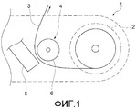
Фиг.1 схематически показывает термографическое печатающее устройство в соответствии с предпочтительным вариантом осуществления изобретения.Figure 1 schematically shows a thermographic printing device in accordance with a preferred embodiment of the invention.
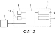
Фиг.2 представляет собой блок-схему управления термографическим печатающим устройством, показанным на фиг.1.Figure 2 is a control block diagram of the thermographic printing device shown in figure 1.
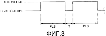
Фиг.3 представляет собой временную диаграмму активизирующего сигнала управления (строб-сигнала), приложенного к схеме управления нагревательным элементом во время высокоскоростной печати.Figure 3 is a timing diagram of an activating control signal (strobe signal) applied to a heating element control circuit during high speed printing.
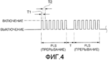
Фиг.4 представляет собой временную диаграмму активизирующего сигнала управления (строб-сигнала), приложенного к схеме управления нагревательным элементом во время низкоскоростной печати.Figure 4 is a timing chart of an activating control signal (strobe signal) applied to a heating element control circuit during low speed printing.
Подробное описание вариантов осуществленияDetailed Description of Embodiments
Предпочтительный вариант осуществления термографического печатающего устройства согласно изобретению подробно описан ниже со ссылкой на сопровождающие чертежи.A preferred embodiment of a thermographic printing apparatus according to the invention is described in detail below with reference to the accompanying drawings.
Общая конфигурацияGeneral configuration
Как показано на фиг.1, термографическое печатающее устройство 1 имеет отсек 2 для бумажного рулона, предназначенный для хранения бумажного рулона, который представляет собой непрерывную бумагу для записи, свернутую в рулон, механизм 4 подачи бумаги для записи (средства подачи), который подает бумагу 3 для записи, выводимую из бумажного рулона, который хранится в отсеке 2 для бумажного рулона, через канал подачи внутри печатающего устройства, и термопечатающую головку 5, которая расположена обращенной нагревательной частью к позиции печати канала подачи. В качестве бумаги 3 для записи используется рулонная термобумага или, например, бумага для печатания этикеток с этикетками из термобумаги, прикрепленными к непрерывному лайнеру.As shown in FIG. 1, the
Механизм 4 подачи бумаги для записи содержит опорный валик 6, расположенный напротив термопечатающей головки 5, и электродвигатель подачи (не показанный), который приводит в действие опорный валик 6. Бумага 3 для записи, подаваемая из бумажного рулона, загружается так, что она проходит между термопечатающей головкой 5 и опорным валиком 6, и бумага 3 для записи подается совместно с вращением опорного валика 6, контактирующего с бумагой 3 для записи.The recording
На термопечатающей головке 5 в массиве по ширине бумаги 3 для записи напротив опорного валика 6 располагается множество нагревательных элементов. Когда нагревательные элементы прижимаются к бумаге 3 для записи, удерживаемой между термопечатающей головкой 5 и опорным валиком 6, и затем прикладывается определенное напряжение, вызывая нагревание конкретного нагревательного элемента, часть бумаги 3 для записи, касающаяся активированного нагревательного элемента, нагревается и меняет цвет, и образуется печатная точка. В термопечатающей головке 5 для обнаружения температуры окружающего воздуха располагается термистор или другой температурный датчик 7 (см. фиг.2).On the
Термопечатающая головка 5 может независимо управлять и нагревать каждый из нагревательных элементов, и выборочно управлять нагревательными элементами, соответствующими тем положениям, где должны быть напечатаны точки, в соответствии с пиксельными данными для каждой линии точек данных печати. В результате, на бумаге 3 для записи одновременно образуется ряд печатных точек, соответствующих пиксельным данным каждой строки точек в данных печати. Термографическое печатающее устройство 1 печатает на бумаге 3 для записи с помощью вращения опорного валика 6 и подачи бумаги 3 для записи синхронно с операцией печати каждой строки точек.The
Как показано на фиг.2, управляющий модуль 8 (средства управления) термографического печатающего устройства 1 содержит центральный процессор, постоянное запоминающее устройство и оперативную память (ОЗУ). Программное обеспечение (программно-аппаратное обеспечение) и данные для выполнения различных функций термографического печатающего устройства 1 хранятся в постоянном запоминающем устройстве, и различные функции термографического печатающего устройства 1 осуществляются в результате чтения и исполнения их процессором. ОЗУ работает как устройство временного хранения данных, необходимых для реализации функций термографического печатающего устройства 1. В дополнение к этим частям, составляющим блок 8 управления, на управляющей монтажной плате внутри термографического печатающего устройства 1 расположены интерфейс связи, приводной механизм электродвигателя для управления подающим электродвигателем и интегральные схемы (матрицы логических элементов) для управления термопечатающей головкой 5.As shown in FIG. 2, the control module 8 (control means) of the
Блок 8 управления присоединяется через интерфейс связи к центральному компьютеру или другому главному устройству 9, данные печати и команды управления отправляются с центрального устройства 9 на блок 8 управления. Сигналы датчиков с различных датчиков, таких как датчик температуры, также вводятся в блок 8 управления.The
Управление активизацией термопечатающей головкиThermal head activation control
Фиг.3 изображает активизирующий управляющий сигнал (строб-сигнал), приложенный к схемам управления нагревательными элементами термопечатающей головки при высокоскоростной печати, а фиг.4 изображает активизирующий управляющий сигнал (строб-сигнал), приложенный к схемам управления нагревательными элементами термопечатающей головки при низкоскоростной печати. К схеме управления прикладывается заданное напряжение, и при включении строб-сигнала активизируется нагревательный элемент, а при выключении строб-сигнала активизация прекращается. Приложенное напряжение при включенном строб-сигнале является постоянным.Figure 3 depicts an activating control signal (strobe signal) applied to control circuits of heating elements of a thermal head during high-speed printing, and Figure 4 depicts an activating control signal (strobe signal) applied to control circuits of heating elements of a thermal head during low-speed printing . A predetermined voltage is applied to the control circuit, and when the strobe signal is turned on, the heating element is activated, and when the strobe signal is turned off, activation is stopped. The applied voltage when the strobe signal is on is constant.
Как показано на фиг.3, когда скорость подачи бумаги для записи высокая, подается строб-сигнал, который остается постоянно включенным в течение периода активизации PLS (первый период) для образования одной печатной точки, и активизация продолжается в течение этого периода. Когда скорость подачи бумаги для записи низкая, подается строб-сигнал, разделенный на короткие импульсы, как показано на фиг.4, и прерывание сигнала, прикладывающее короткие активизирующие импульсы, происходит в течение всего периода активизации PLS. Активизация посредством прерывания сигнала чередуется между короткими активизирующими периодами, составляющими импульсы активизации (период Т1 включения импульса, второй период), и периодами деактивизации (период Т2 выключения импульса, третий период) между периодами активизации.As shown in FIG. 3, when the recording paper feed speed is high, a strobe signal is provided that remains continuously on during the PLS activation period (first period) to form one printing point, and activation continues during this period. When the recording paper feed speed is low, a strobe signal is divided into short pulses, as shown in FIG. 4, and a signal interruption applying short activating pulses occurs throughout the entire PLS activation period. Activation by interruption of the signal alternates between short activating periods making up the activation pulses (pulse switching period T1, second period) and deactivation periods (pulse switching period T2, third period) between the activation periods.
Скорость подачи бумаги для записи, которая используется в качестве порогового значения при непрерывной активизации или прерывании сигнала, может быть установлена по желанию, например, 60 мм/сек. Блок 8 управления управляет активизацией, как показано на фиг.4, когда скорость подачи бумаги для записи во время формирования печатных точек меньше или равна этому пороговому значению. Более конкретно, блок 8 управления определяет скорость подачи бумаги для записи в определенные моменты во время операции печати с помощью определения скорости подающего электродвигателя и механизма 4 подачи бумаги для записи, определяет, меньше или равна найденная скорость подачи бумаги для записи пороговому значению, и на основании результата этого решения определяет, нужно ли использовать прерывание сигнала.The recording paper feed rate, which is used as a threshold value for continuously activating or interrupting the signal, can be set as desired, for example, 60 mm / sec. The
Период активизации PLS (первый период) является периодом активизации, который определяет, как долго нагревательный элемент удерживается в контакте с и нагревает место формирования печатной точки бумаги 3 для записи. Между концом периода активизации PLS, формирующим одну печатную точку, и началом периода активизации PLS, формирующим следующую печатную точку, предусматривается специальная пауза Т активации. Длительность периода активизации PLS определяется согласно скорости подачи бумаги для записи и является короткой во время высокоскоростной печати и длинной при низкоскоростной печати. Отношение между периодом активизации PLS и временем деактивизации T может быть задано по желанию.The activation period PLS (first period) is an activation period that determines how long the heating element is held in contact with and heats the formation of the printing point of the
Продолжительность и отношение между периодом Т1 включения прерывания сигнала (второй период) и периодом Т2 отключения прерывания сигнала (третий период) устанавливаются заранее в соответствующие значения. В этом варианте осуществления изобретения период Т1 включения прерывания сигнала установлен в постоянное значение и остается постоянным при всех условиях и установках печати. Однако период Т2 выключения прерывания сигнала может быть настроен с помощью управления двухрядным переключателем 10 (средства настройки, см. фиг.2), расположенным в термографическом печатающем устройстве 1. Пользователь может оперировать двухрядным переключателем 10 и менять время включения импульсов активизации. Это позволяет изменять общее время активизации периода активизации PLS, изменяя, таким образом, теплоотдачу и температуру нагрева бумаги 3 для записи при формировании печатных точек и настройки плотности печатных точек.The duration and relationship between the period T1 of switching on the signal interruption (second period) and the period T2 of switching off the signal interruption (third period) are set in advance to the corresponding values. In this embodiment, the signal interruption enable period T1 is set to a constant value and remains constant under all printing conditions and settings. However, the period T2 of switching off the signal interruption can be adjusted by controlling the double-row switch 10 (settings, see FIG. 2) located in the
Команда установки плотности печати также может быть направлена главным устройством 9 на блок 8 управления, и установка периода Т2 выключения прерывания сигнала может быть изменена на основе этой команды установки плотности печати. Команда установки плотности печати также может быть включена в данные печати, и плотность печати может настраиваться соответственно при печати.The print density setting command can also be directed by the
Как описано выше, в этом варианте осуществления изобретения в течение всего периода активизации PLS (первого периода) используется прерывание сигнала, который нагревает бумагу 3 для записи и формирует печатные точки с помощью нагревательных элементов термопечатающей головки 5 при низкоскоростной печати, и может, таким образом, защитить нагревательные элементы от перегрева при низкоскоростной печати. Прилипание, таким образом, может быть уменьшено, и может быть предотвращена потеря качества печати.As described above, in this embodiment, during the entire PLS activation period (first period), a signal interruption is used, which heats the
Другие варианты осуществленияOther options for implementation
(1) Вариант осуществления, описанный выше, регулирует период отключения прерывания сигнала T2 на основе плотности печати, но вместо или в дополнение к плотности печати могут быть использованы и другие параметры. Например, установка периода T2 отключения прерывания сигнала может быть изменена в зависимости от окружающей температуры термопечатающей головки 5, которая определяется датчиком температуры 7. Поскольку это позволяет настраивать тепловыделение согласно окружающей температуре, температура нагрева бумаги 3 для записи может всегда быть сохранена в соответствующем диапазоне. Период Т2 отключения прерывания сигнала также может быть настроен в соответствии с типом бумаги 3 для записи для адаптации к различиям условий прилипания из-за типа бумаги 3 для записи. Кроме того, в качестве альтернативы, период T2 отключения прерывания сигнала может быть настроен в зависимости от таких характеристик, как приложенное напряжение при активизации нагревательных элементов и характеристики аккумулирования тепла термопечатающей головки 5. Период T2 отключения прерывания сигнала может быть также настроен согласно скорости подачи бумаги для записи. Например, период отключения прерывания может быть увеличен, как только скорость подачи бумаги для записи уменьшается.(1) The embodiment described above adjusts the interrupt period of the T2 signal based on print density, but other parameters can be used instead of or in addition to print density. For example, the setting of the signal interruption off period T2 can be changed depending on the ambient temperature of the
(2) Период Т1 включения прерывания сигнала постоянен, а период T2 отключения прерывания сигнала регулируется на основе различных параметров в варианте осуществления, описанном выше, но как период Т1 включения прерывания сигнала, так и период T2 отключения прерывания сигнала могут быть сокращены при уменьшении скорости подачи бумаги для записи. Также возможно изменение только периода Т1 включения прерывания сигнала вместо изменения периода T2 отключения прерывания сигнала на основе разных параметров.(2) The signal interrupt enable period T1 is constant, and the signal interrupt disable period T2 is adjusted based on various parameters in the embodiment described above, but both the signal interrupt enable period T1 and the signal interrupt disable period T2 can be shortened by decreasing the feed rate paper for recording. It is also possible to change only the signal interruption enable period T1 instead of changing the signal interruption disable period T2 based on different parameters.
(3) Порог скорости для определения того, нужно ли использовать прерывание сигнала или непрерывную активизацию, составляет 60 мм/сек в предшествующем варианте осуществления, но это значение может быть надлежащим образом изменено, например, в соответствии с типом бумаги 3 для записи и окружающей температурой термопечатающей головки 5.(3) The speed threshold for determining whether to use a signal interruption or continuous activation is 60 mm / s in the previous embodiment, but this value can be appropriately changed, for example, according to the type of
Claims (7)
генерированием первого активизирующего импульса, который непрерывно действует в течение первого периода для формирования печатной точки в случае, когда скорость подачи носителя для записи больше заданного порогового значения; и
генерированием второго активизирующего импульса, который изменяется в течение указанного первого периода между активизацией во втором периоде, который короче, чем первый период, и деактивизацией в течение третьего периода в случае, когда скорость подачи носителя для записи меньше или равна указанному пороговому значению.1. A method of controlling the activation of a thermographic printing device having a thermal head with a heating element heating the recording medium and forming a print point by activating the heating element, characterized in:
generating a first activating pulse that continuously operates during the first period to form a print point in the case where the feed rate of the recording medium is greater than a predetermined threshold value; and
generating a second activation pulse that changes during said first period between activation in the second period, which is shorter than the first period, and deactivation during the third period in the case where the feed rate of the recording medium is less than or equal to the specified threshold value.
термопечатающую головку с нагревательным элементом;
средства перемещения, которые перемещают носитель для записи, прошедший положение, расположенное напротив термопечатающей головки; и
средства управления, которые нагревают носитель для записи и формируют печатную точку с помощью активизации нагревательного элемента;
при этом средства управления генерируют первый активизирующий импульс, который действует непрерывно в течение первого периода для формирования печатной точки в случае, когда скорость перемещения носителя для записи с помощью средств перемещения больше, чем заданное пороговое значение, и
генерируют второй активизирующий импульс, который изменяется в течение первого периода между активизацией во втором периоде, который меньше, чем первый период, и деактивизацией в течение третьего периода в случае, когда скорость подачи носителя информации меньше или равна указанному пороговому значению.5. Thermographic printing device containing:
a thermal head with a heating element;
moving means that move the recording medium past a position opposite the thermal head; and
controls that heat the recording medium and form a print point by activating a heating element;
wherein the control means generate a first activating pulse, which operates continuously during the first period to form a print point in the case where the speed of movement of the recording medium by means of the movement is greater than a predetermined threshold value, and
generate a second activating pulse, which changes during the first period between activation in the second period, which is less than the first period, and deactivation during the third period in the case when the feed rate of the information carrier is less than or equal to the specified threshold value.
регулирующие средства, которые изменяют по меньшей мере один из второго периода и третьего периода во втором активизирующем импульсе согласно по меньшей мере одному из плотности точек печати и окружающей температуры термопечатающей головки.6. The printing device according to claim 5, characterized in that it further comprises:
regulating means that change at least one of the second period and the third period in the second activation pulse according to at least one of the density of the print points and the ambient temperature of the thermal head.
средствами управления, генерирующими второй активирующий импульс с помощью прерывания сигнала. 7. The printing device according to claim 5, characterized in:
controls generating a second activating pulse by interrupting the signal.
Applications Claiming Priority (3)
| Application Number | Priority Date | Filing Date | Title |
|---|---|---|---|
| JP2009251746A JP5540653B2 (en) | 2009-11-02 | 2009-11-02 | Thermal printer and its energization control method |
| JP2009-251746 | 2009-11-02 | ||
| PCT/JP2010/068989 WO2011052603A1 (en) | 2009-11-02 | 2010-10-26 | Thermal printer and method for controlling current passage therein |
Publications (2)
| Publication Number | Publication Date |
|---|---|
| RU2012117766A RU2012117766A (en) | 2013-12-10 |
| RU2503545C1 true RU2503545C1 (en) | 2014-01-10 |
Family
ID=43922028
Family Applications (1)
| Application Number | Title | Priority Date | Filing Date |
|---|---|---|---|
| RU2012117766/12A RU2503545C1 (en) | 2009-11-02 | 2010-10-26 | Thermal printer and method of its operation |
Country Status (9)
| Country | Link |
|---|---|
| US (1) | US8638351B2 (en) |
| EP (2) | EP2497644B1 (en) |
| JP (1) | JP5540653B2 (en) |
| KR (1) | KR101422967B1 (en) |
| CN (2) | CN104129168B (en) |
| BR (1) | BR112012001703A2 (en) |
| ES (1) | ES2522534T3 (en) |
| RU (1) | RU2503545C1 (en) |
| WO (1) | WO2011052603A1 (en) |
Families Citing this family (11)
| Publication number | Priority date | Publication date | Assignee | Title |
|---|---|---|---|---|
| JP2012016874A (en) * | 2010-07-07 | 2012-01-26 | Toshiba Tec Corp | Printer and program |
| JP2016026922A (en) * | 2014-07-07 | 2016-02-18 | セイコーエプソン株式会社 | Printer, printer control method, and storage medium |
| US10592794B2 (en) | 2014-10-13 | 2020-03-17 | Avery Dennison Retail Information Services, Llc | Industrial printer |
| GB201419463D0 (en) * | 2014-10-31 | 2014-12-17 | Videojet Technologies Inc | Printer and method |
| US10286694B2 (en) * | 2016-09-02 | 2019-05-14 | Datamax-O'neil Corporation | Ultra compact printer |
| JP6747208B2 (en) * | 2016-09-21 | 2020-08-26 | カシオ計算機株式会社 | Printing device, printing device control method, and program |
| JP2018144447A (en) * | 2017-03-09 | 2018-09-20 | カシオ計算機株式会社 | Printing apparatus, printing system, printing control method, and program |
| JP6805906B2 (en) * | 2017-03-10 | 2020-12-23 | カシオ計算機株式会社 | Printing equipment, printing system, printing control method, and program |
| JP7012476B2 (en) * | 2017-07-21 | 2022-01-28 | 東芝テック株式会社 | Printer |
| JP2019181819A (en) * | 2018-04-11 | 2019-10-24 | 東芝テック株式会社 | Thermal printer |
| CN111913054B (en) * | 2019-05-10 | 2021-09-21 | 株洲中车时代电气股份有限公司 | Method and system for diagnosing over-temperature fault of chopping wave and transmission control device |
Citations (4)
| Publication number | Priority date | Publication date | Assignee | Title |
|---|---|---|---|---|
| JPH0725052A (en) * | 1993-07-15 | 1995-01-27 | Brother Ind Ltd | Thermal head drive |
| JPH07227990A (en) * | 1994-02-21 | 1995-08-29 | Yokogawa Electric Corp | Thermal recording device |
| JPH1148510A (en) * | 1997-08-07 | 1999-02-23 | Alps Electric Co Ltd | Printer and its method for recording |
| WO2007057779A2 (en) * | 2005-10-25 | 2007-05-24 | Dymo | Tape printing apparatus |
Family Cites Families (21)
| Publication number | Priority date | Publication date | Assignee | Title |
|---|---|---|---|---|
| JPS63199661A (en) * | 1987-02-16 | 1988-08-18 | Seiko Epson Corp | Handy printer printing control device |
| JPH01186338A (en) * | 1988-01-21 | 1989-07-25 | Canon Inc | Image recording method |
| DE69031927T2 (en) * | 1989-07-19 | 1998-07-09 | Canon Kk | Apparatus and method for recording |
| JPH03109842A (en) * | 1989-09-25 | 1991-05-09 | Ricoh Co Ltd | Signal transmission method between OA devices |
| JPH03109842U (en) * | 1990-02-28 | 1991-11-12 | ||
| JP2914128B2 (en) | 1993-11-18 | 1999-06-28 | ブラザー工業株式会社 | Driving device for heating element of thermal head |
| US5608442A (en) * | 1994-08-31 | 1997-03-04 | Lasermaster Corporation | Heating control for thermal printers |
| JPH08118704A (en) | 1994-10-28 | 1996-05-14 | Hitachi Ltd | Thermal recorder |
| JP2993441B2 (en) * | 1996-10-08 | 1999-12-20 | 松下電器産業株式会社 | Driving method of thermal line printer |
| JPH11268317A (en) | 1998-03-20 | 1999-10-05 | Seiko Epson Corp | Printing method and apparatus |
| JP2000185424A (en) * | 1998-12-21 | 2000-07-04 | Seiko Instruments Inc | Method for controlling history of thermal printer |
| JP2005040971A (en) * | 2003-07-22 | 2005-02-17 | Alps Electric Co Ltd | Printer and its recording method |
| JP2005231180A (en) * | 2004-02-19 | 2005-09-02 | Toshiba Tec Corp | Line thermal printer |
| JP2005313481A (en) * | 2004-04-28 | 2005-11-10 | Fuji Photo Film Co Ltd | Image forming apparatus and method of correcting density variation |
| TWM269511U (en) | 2004-10-14 | 2005-07-01 | Shiuan-Yu Lin | Improved mouse device of notebook computer |
| US7542060B2 (en) * | 2005-07-25 | 2009-06-02 | Seiko Epson Corporation | Thermal printer and thermal printer control method |
| JP4992313B2 (en) | 2005-07-25 | 2012-08-08 | セイコーエプソン株式会社 | Thermal printer and control method thereof |
| US7319473B2 (en) * | 2005-12-22 | 2008-01-15 | Carestream Health, Inc. | Thermal recording system and method |
| JP4841616B2 (en) * | 2006-03-01 | 2011-12-21 | シチズンホールディングス株式会社 | Thermal printer |
| JP5048570B2 (en) | 2008-04-02 | 2012-10-17 | 京セラドキュメントソリューションズ株式会社 | Printing system and printer |
| JP2010089354A (en) * | 2008-10-07 | 2010-04-22 | Seiko Instruments Inc | Printing method for thermal printer, computer program, and thermal printer apparatus |
-
2009
- 2009-11-02 JP JP2009251746A patent/JP5540653B2/en not_active Expired - Fee Related
-
2010
- 2010-10-26 WO PCT/JP2010/068989 patent/WO2011052603A1/en not_active Ceased
- 2010-10-26 BR BR112012001703-9A patent/BR112012001703A2/en not_active Application Discontinuation
- 2010-10-26 CN CN201410341508.8A patent/CN104129168B/en active Active
- 2010-10-26 KR KR1020127011389A patent/KR101422967B1/en active Active
- 2010-10-26 EP EP10826735.2A patent/EP2497644B1/en active Active
- 2010-10-26 ES ES10826735.2T patent/ES2522534T3/en active Active
- 2010-10-26 CN CN201080048253.6A patent/CN102596578B/en active Active
- 2010-10-26 EP EP14185093.3A patent/EP2823964B1/en active Active
- 2010-10-26 RU RU2012117766/12A patent/RU2503545C1/en active
- 2010-10-26 US US13/505,603 patent/US8638351B2/en active Active
Patent Citations (4)
| Publication number | Priority date | Publication date | Assignee | Title |
|---|---|---|---|---|
| JPH0725052A (en) * | 1993-07-15 | 1995-01-27 | Brother Ind Ltd | Thermal head drive |
| JPH07227990A (en) * | 1994-02-21 | 1995-08-29 | Yokogawa Electric Corp | Thermal recording device |
| JPH1148510A (en) * | 1997-08-07 | 1999-02-23 | Alps Electric Co Ltd | Printer and its method for recording |
| WO2007057779A2 (en) * | 2005-10-25 | 2007-05-24 | Dymo | Tape printing apparatus |
Also Published As
| Publication number | Publication date |
|---|---|
| EP2497644A4 (en) | 2013-05-15 |
| EP2823964A2 (en) | 2015-01-14 |
| ES2522534T3 (en) | 2014-11-14 |
| JP5540653B2 (en) | 2014-07-02 |
| BR112012001703A2 (en) | 2020-10-27 |
| CN104129168B (en) | 2016-05-18 |
| EP2823964A3 (en) | 2015-07-01 |
| JP2011093267A (en) | 2011-05-12 |
| EP2823964B1 (en) | 2018-09-05 |
| US20120218366A1 (en) | 2012-08-30 |
| KR101422967B1 (en) | 2014-07-23 |
| CN104129168A (en) | 2014-11-05 |
| WO2011052603A1 (en) | 2011-05-05 |
| CN102596578B (en) | 2014-08-13 |
| RU2012117766A (en) | 2013-12-10 |
| KR20120076370A (en) | 2012-07-09 |
| CN102596578A (en) | 2012-07-18 |
| EP2497644A1 (en) | 2012-09-12 |
| US8638351B2 (en) | 2014-01-28 |
| EP2497644B1 (en) | 2014-10-08 |
Similar Documents
| Publication | Publication Date | Title |
|---|---|---|
| RU2503545C1 (en) | Thermal printer and method of its operation | |
| JP3750750B2 (en) | Inkjet printer | |
| US8384750B2 (en) | Printing apparatus | |
| EP2279874B1 (en) | Printer | |
| JP2012016874A (en) | Printer and program | |
| EP1878580B1 (en) | Recording apparatus | |
| JP2011088370A (en) | Thermal printer and energization control method thereof | |
| JP6720799B2 (en) | Printing device, printing device control method, and program | |
| US9073346B1 (en) | Method for thermal head energizing time control at astable voltage | |
| JP2002137434A (en) | Apparatus and method for controlling thermal head | |
| JP5017833B2 (en) | Printer and thermal head preheat control method | |
| JP2023069460A (en) | Program, printer control method and printer | |
| JP4006710B2 (en) | Thermal printer | |
| JPS61197257A (en) | Thermal transfer type printer | |
| JP2001328291A (en) | Method of controlling printing for thermal transfer line printer, and thermal transfer line printer | |
| JP2008162107A (en) | Thermal printer and printing controller | |
| JPH01237167A (en) | recording device | |
| JP2005169936A (en) | Printing device | |
| KR100412768B1 (en) | Thermal Printer | |
| JP2008221558A (en) | Printer apparatus and printing method | |
| JPH10157136A (en) | Ink jet recorder and recording method | |
| JP2006192756A (en) | Thermal printer | |
| JP2010005909A (en) | Recording controller | |
| JP2007203629A (en) | Recorder | |
| JP2014046521A (en) | Thermal transfer recording device |