EP2823964B1 - Thermal printer and energizing control method therefor - Google Patents
Thermal printer and energizing control method therefor Download PDFInfo
- Publication number
- EP2823964B1 EP2823964B1 EP14185093.3A EP14185093A EP2823964B1 EP 2823964 B1 EP2823964 B1 EP 2823964B1 EP 14185093 A EP14185093 A EP 14185093A EP 2823964 B1 EP2823964 B1 EP 2823964B1
- Authority
- EP
- European Patent Office
- Prior art keywords
- period
- energizing
- chopping
- thermal head
- recording medium
- Prior art date
- Legal status (The legal status is an assumption and is not a legal conclusion. Google has not performed a legal analysis and makes no representation as to the accuracy of the status listed.)
- Active
Links
- 238000000034 method Methods 0.000 title claims description 16
- 238000010438 heat treatment Methods 0.000 description 8
- 230000015572 biosynthetic process Effects 0.000 description 3
- 238000009500 colour coating Methods 0.000 description 2
- 238000004891 communication Methods 0.000 description 2
- 230000007423 decrease Effects 0.000 description 2
- 230000001419 dependent effect Effects 0.000 description 2
- 238000013021 overheating Methods 0.000 description 2
- 238000009877 rendering Methods 0.000 description 2
- 230000001360 synchronised effect Effects 0.000 description 2
- 238000001816 cooling Methods 0.000 description 1
- 230000003247 decreasing effect Effects 0.000 description 1
- 238000001514 detection method Methods 0.000 description 1
- 238000010586 diagram Methods 0.000 description 1
- 230000000694 effects Effects 0.000 description 1
- 238000005338 heat storage Methods 0.000 description 1
- 239000000155 melt Substances 0.000 description 1
Images


Classifications
-
- B—PERFORMING OPERATIONS; TRANSPORTING
- B41—PRINTING; LINING MACHINES; TYPEWRITERS; STAMPS
- B41J—TYPEWRITERS; SELECTIVE PRINTING MECHANISMS, i.e. MECHANISMS PRINTING OTHERWISE THAN FROM A FORME; CORRECTION OF TYPOGRAPHICAL ERRORS
- B41J2/00—Typewriters or selective printing mechanisms characterised by the printing or marking process for which they are designed
- B41J2/315—Typewriters or selective printing mechanisms characterised by the printing or marking process for which they are designed characterised by selective application of heat to a heat sensitive printing or impression-transfer material
- B41J2/32—Typewriters or selective printing mechanisms characterised by the printing or marking process for which they are designed characterised by selective application of heat to a heat sensitive printing or impression-transfer material using thermal heads
- B41J2/35—Typewriters or selective printing mechanisms characterised by the printing or marking process for which they are designed characterised by selective application of heat to a heat sensitive printing or impression-transfer material using thermal heads providing current or voltage to the thermal head
- B41J2/355—Control circuits for heating-element selection
Landscapes
- Electronic Switches (AREA)
Description
- The present invention relates to a thermal printer that forms print dots on recording paper by energizing and heating the heat elements of a thermal printhead, and to an energizing control method therefor.
- Thermal printers that convey thermal paper or other recording paper between a thermal head and a platen roller, and energize and heat the heat elements of the thermal head to produce color and form print dots where the recording paper contacts the heat elements, control energizing the heat elements at the print dot positions synchronized to conveyance of the recording paper, and thereby control the heating temperature and the time heat is applied to the print dot formation position to form print dots of the desired size.
- A thermal printer that considers the effect of speed variations to control energizing the thermal head when the conveyance speed of the recording paper (the printing speed) varies according to various parameters is described in
Patent Reference 1.Patent Reference 1 describes determining the energizing time with consideration for cooling during the de-energized time because the de-energized time between print dots increases compared with printing at normal speed when the thermal head is energized while printing at low speed. More specifically, in order to reduce excessive heat buildup resulting from continuous energizing when print dots are formed continuously, the heating time is reduced for the print dots that are formed later, and this time reduction is reduced during low-speed printing. InJP 2005 040971 A - A further method for heating thermal heads of a printer is known from
JP 63 199661 A - Patent Reference 1: Japan Patent No.
2007-55239 - When printing with a low recording paper (thermal paper) conveyance speed, a phenomenon called "sticking" in which the color coating on the thermal paper melts and sticks to the thermal head can occur. When sticking occurs, print quality drops because normal paper conveyance is inhibited and the paper conveyance speed can vary.
- With consideration for this problem, an object of the present invention is to provide a thermal printer and energizing control method therefor that can reduce sticking during low speed printing and improve print quality.
- To solve the aforementioned_problem, the invention proposes a energizing control method as defined in
claim 1. Further preferred embodiments of said method are defined in thedependent claims 2 to 4. - Further it is provided a thermal printer with the features defined in
claim 5. Further preferred embodiments of said printer are defined inclaims - According to an aspect, an energizing control method for a thermal printer having a thermal head with a heat element that heats a recording medium and forms a print dot by energizing the heat element comprises: generating a first energizing pulse that energizes continuously during a first period for forming a print dot when the recording medium conveyance speed is greater than a specific threshold value; and generating a second energizing pulse that alternates during the first period between energizing for a second period that is shorter than the first period and de-energizing for a third period when the recording medium conveyance speed is less than or equal to the threshold value.
- By energizing intermittently during a first period during so-called low speed printing, heat output can be suppressed while the heat elements heat the recording medium, and the heat elements can be prevented from overheating. The heat elements being heated can therefore be held at an appropriate temperature, and the color coating on the surface of the recording medium can be prevented from being melted by a high temperature heat element. A drop in print quality due to sticking can therefore be reduced.
- At least one of the second period and the third period in the second energizing pulse can also be varied according to at least one of the print dot density and the ambient temperature of the thermal head. Because heat output can be adjusted by increasing or decreasing the de-energized time in this configuration, the heating temperature can be adjusted to an appropriate range and print quality can be improved.
- Alternatively, the second period may be held constant and the third period varied in the second energizing pulse.
- Alternatively, the second energizing pulse maybe generated by signal chopping.
- Another aspect relates to a thermal printer having a thermal head with a heat element; a conveyance means that conveys a recording medium passed a position opposite the thermal head; and a control means that heats the recording medium and forms a print dot by energizing the heat element; wherein the control means generates a first energizing pulse that energizes continuously during a first period for forming a print dot when the conveyance speed of the recording medium by means of the conveyance means is greater than a specific threshold value, and generates a second energizing pulse that alternates during the first period between energizing for a second period that is shorter than the first period and de-energizing for a third period when the conveyance speed is less than or equal to the threshold value.
- The printer may also have an adjustment means that changes at least one of the second period and the third period in the second energizing pulse according to at least one of the print dot density and the ambient temperature of the thermal head. This configuration enables the user to change the settings appropriately according to the required quality.
- The control means may also be configured to generate the second energizing pulse by signal chopping.
-
-
FIG. 1 schematically describes a thermal printer according to a preferred embodiment of the invention. -
FIG. 2 is a control block diagram of the thermal printer shown inFIG. 1 . -
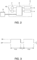
FIG. 3 is a timing chart of the energizing control signal (strobe signal) applied to the heat element drive circuit during high speed printing. -
FIG. 4 is a timing chart of the energizing control signal (strobe signal) applied to the heat element drive circuit during low speed printing. - A preferred embodiment of a thermal printer according to the invention is described in detail below with reference to the accompanying figures.
- As shown in
FIG. 1 , thethermal printer 1 has aroll paper compartment 2 for storing roll paper, which is continuous recording paper wound in a roll, a recording paper conveyance mechanism 4 (conveyance means) that conveysrecording paper 3 delivered from the paper roll stored in theroll paper compartment 2 through a conveyance path inside the printer, and athermal head 5 that is disposed with the heating part facing the printing position of the conveyance path. Continuous thermal paper or label paper having labels made of thermal paper affixed to a continuous liner, for example, is used as therecording paper 3. - The recording
paper conveyance mechanism 4 includes aplaten roller 6 disposed opposite thethermal head 5, and a conveyance motor not shown that drives theplaten roller 6. Therecording paper 3 delivered from the paper roll is loaded so that it passes between thethermal head 5 andplaten roller 6, and therecording paper 3 is conveyed in conjunction with rotation of theplaten roller 6 contacting therecording paper 3. - A plurality of heat elements are disposed to the
thermal head 5 in an array widthwise to therecording paper 3 opposite theplaten roller 6. When the heat elements are pressed to therecording paper 3 held between thethermal head 5 andplaten roller 6 and a specific voltage is then applied causing a specific heat element to heat, the part of therecording paper 3 touching the energized heat element is heated and changes color, and a print dot is formed. A thermistor or other temperature sensor 7 (seeFIG. 2 ) is disposed to thethermal head 5 for detecting the nearby ambient temperature. - The
thermal head 5 can independently drive and heat each of the heat elements, and selectively drives the heat elements corresponding to the positions where dots are to be printed according to the pixel data for each dot line in the print data. As a result, a row of print dots corresponding to the pixel data for each dot line in the print data is formed simultaneously on therecording paper 3. Thethermal printer 1 prints on therecording paper 3 by rotating theplaten roller 6 and conveying therecording paper 3 synchronized to the printing operation of each dot line. - As shown in
FIG. 2 , the control unit 8 (control means) of thethermal printer 1 includes a CPU, ROM, and RAM. Software (firmware) and data for rendering various functions of thethermal printer 1 are stored in ROM, and variousthermal printer 1 functions are performed as a result of the CPU reading and executing these. RAM functions as a temporary storage device for data that is required to implementthermal printer 1 functions. In addition to these parts rendering thecontrol unit 8, a communication interface, motor driver for controlling the conveyance motor, and integrated circuits (gate array) for driving thethermal head 5, are disposed to a control circuit board inside thethermal printer 1. - The
control unit 8 is connected through the communication interface to a host computer orother host device 9, and print data and control commands are sent from thehost device 9 to thecontrol unit 8. Detection signals from various sensors such as thetemperature sensor 7 are also input to thecontrol unit 8. -
FIG. 3 shows an energizing control signal (strobe signal) applied to the drive circuits of the heat elements of the thermal head during high speed printing, andFIG. 4 shows an energizing control signal (strobe signal) applied to the drive circuits of the heat elements of the thermal head during low speed printing. A specific voltage is applied to the drive circuit and the heat element is energized when the strobe signal is ON, and energizing stops when the strobe signal is OFF. The voltage applied when the strobe signal is ON is constant. - As shown in
FIG. 3 , when the recording paper conveyance speed is high, a strobe signal that remains continuously ON during the energizing period PLS (first period) for forming one print dot is supplied, and energizing is continuous during this period. When the recording paper conveyance speed is slow, a strobe signal that is divided into short pulses is supplied as shown inFIG. 4 , and signal chopping applying short energizing pulses continues throughout the entire energizing period PLS. Energizing by means of signal chopping alternates between short energizing periods constituting the energizing pulses (chopping-ON period T1; second period), and de-energized periods (chopping-OFF period T2; third period) between the energizing periods. - The recording paper conveyance speed used as the threshold for continuous energizing or signal chopping can be desirably set, and can be set to 60 mm/sec, for example. The
control unit 8 controls energizing as shown inFIG. 4 when the recording paper conveyance speed during print dot formation is less than or equal to this threshold value. More specifically, thecontrol unit 8 determines the recording paper conveyance speed at certain times during the printing operation by detecting the speed of the conveyance motor of the recordingpaper conveyance mechanism 4, determines if the detected recording paper conveyance speed is less than or equal to the threshold speed, and based on the result of this decision determines whether or not to use signal chopping. - The energizing period PLS (first period) is an energizing period that determines how long the heat element is held in contact with and heats the print dot formation position of the
recording paper 3. A specific energizing pause T is provided between the end of the energizing period PLS forming one print dot and the start of the energizing period PLS forming the next print dot. The length of the energizing period PLS is determined according to the recording paper conveyance speed, is short during high speed printing, and is long during low speed printing. The ratio between the energizing period PLS and de-energized time T can be set desirably. - The length of and ratio between the chopping-ON period T1 (second period) and the chopping-OFF period T2 (third period) are set in advance to suitable values . In this embodiment of the invention the chopping-ON period T1 is set to a constant value, and remains constant under all printing conditions and print settings. The chopping-OFF period T2, however, can be adjusted by operating a DIP switch 10 (adjustment means, see
FIG. 2 ) disposed to thethermal printer 1. The user can operate theDIP switch 10 and change the ON time of the energizing pulses. This enables changing the total energizing time of the energizing period PLS, thereby changing the heat output and the heating temperature of therecording paper 3 when forming a print dot, and adjusting the print dot density. - A print density setting command can also be sent from the
host device 9 to thecontrol unit 8, and the chopping-OFF period T2 setting can be changed based on this print density setting command. A print density command can also be included in the print data, and the print density can be adjusted accordingly while printing. - As described above, this embodiment of the invention uses signal chopping throughout the energizing period PLS (first period) that heats the
recording paper 3 and forms print dots by means of the heat elements of thethermal head 5 during low speed printing, and can thereby prevent the heat elements from overheating during low speed printing. Sticking can therefore be reduced and loss of print quality can be prevented. -
- (1) The embodiment described above adjusts the chopping-OFF period T2 based on the print density, but could use other parameters instead of or in addition to the print density. For example, the chopping-OFF period T2 setting can be changed based on the ambient temperature of the
thermal head 5 detected by thetemperature sensor 7. Because this enables adjusting heat output according to the ambient temperature, the heating temperature of therecording paper 3 can always be held to a suitable temperature. The chopping-OFF period T2 can also be adjusted according to the type ofrecording paper 3 to accommodate differences in sticking conditions due to the type ofrecording paper 3. Further alternatively, the chopping-OFF period T2 may be adjusted according to such characteristics as the voltage applied when energizing the heat elements and the heat storage characteristic of thethermal head 5. The chopping-OFF period T2 may also be adjusted according to the recording paper conveyance speed. For example, the chopping-OFF period could be increased as the recording paper conveyance speed decreases. - (2) The chopping-ON period T1 is constant and the chopping-OFF period T2 is adjustable based on various parameters in the embodiment described above, but both the chopping-ON period T1 and chopping-OFF period T2 could be variable. For example, both the chopping-ON period T1 and chopping-OFF period T2 could be shortened as the recording paper conveyance speed decreases. Changing only the chopping-ON period T1 instead of changing the chopping-OFF period T2 based on various parameters is also conceivable.
- (3) The threshold speed for determining whether to use signal chopping or continuous energizing is 60 mm/sec in the foregoing embodiment, but this value can be suitably changed according to the type of
recording paper 3 and the ambient temperature of thethermal head 5, for example. - Further aspects of the invention are listed in the items below.
- According to a first item, an energizing control method for a thermal printer having a thermal head with a heat element that heats a recording medium and forms a print dot by energizing the heat element comprises: generating a first energizing pulse that energizes continuously during a first period for forming a print dot when the recording medium conveyance speed is greater than a specific threshold value; and generating a second energizing pulse that alternates during the first period between energizing for a second period that is shorter than the first period and de-energizing for a third period when the recording medium conveyance speed is less than or equal to the threshold value.
- According to a second item, the energizing control method of the first item further comprises: enabling varying at least one of the second period and the third period in the second energizing pulse according to at least one of the print dot density and the ambient temperature of the thermal head.
- According to a third item, the energizing control method of the second item further comprises: holding the second period constant and varying the third period in the second energizing pulse.
- According to a fourth item, the energizing control method of the first item further comprises: generating the second energizing pulse by signal chopping.
- According to a fifth item, a thermal printer comprises: a thermal head with a heat element; a conveyance means that conveys a recording medium passed a position opposite the thermal head; and a control means that heats the recording medium and forms a print dot by energizing the heat element, wherein the control means generates a first energizing pulse that energizes continuously during a first period for forming a print dot when the conveyance speed of the recording medium by means of the conveyance means is greater than a specific threshold value, and generates a second energizing pulse that alternates during the first period between energizing for a second period that is shorter than the first period and de-energizing for a third period when the conveyance speed is less than or equal to the threshold value.
- According to a sixth item, the printer of the fifth item further comprises: an adjustment means that changes at least one of the second period and the third period in the second energizing pulse according to at least one of the print dot density and the ambient temperature of the thermal head.
- According to a seventh item, in the printer of the fifth item, the control means generates the second energizing pulse by signal chopping.
- This application is based upon Japanese Patent Application
2009-251746 filed on November 2, 2009
Claims (7)
- An energizing control method for a thermal printer (1) having a thermal head (5) with a heat element that heats a recording medium and forms a print dot by energizing the heat element, comprises the step of generating a first energizing pulse that energizes continuously during a first period (PLS) for forming a print dot when the recording medium conveyance speed is greater than a specific threshold value; and characterised in that the method further comprises the step of generating a second energizing pulse that alternates during a period (PLS CHOPPING) that is longer than the first period (PLS) when the recording medium conveyance speed is less than or equal to the threshold value, wherein the second energizing pulse alternates between energizing for a second period (T1) that is shorter than the period of the second energizing pulse (PLS CHOPPING) and de-energizing for a third period (T2).
- The energizing control method described in claim 1, characterized by:
enabling varying at least one of the second period (T1) and the third period (T2) in the second energizing pulse according to at least one of the print dot density and the ambient temperature of the thermal head (5). - The energizing control method described in claim 2, characterized by:
holding the second period (T1) constant and varying the third period (T3) in the second energizing pulse. - The energizing control method described in claim 1, characterized by:
generating the second energizing pulse by signal chopping. - A thermal printer (1) comprising:a thermal head (5) with a heat element;a conveyance means (6) that conveys a recording medium (3) passed a position opposite the thermal head (5); anda control means (8) that heats the recording medium (3) and forms a print dot by energizing the heat element;wherein the control means is configured to generate a first energizing pulse that energizes continuously during a first period (PLS) for forming a print dot when the conveyance speed of the recording medium by means of the conveyance means (6) is greater than a specific threshold value, and is configured to generate a second energizing pulse that alternates during a period (PLS CHOPPING) that is longer than the first period when the recording medium conveyance speed is less than or equal to the threshold value, wherein the second energizing pulse alternates between energizing for a second period (T1) that is shorter than the period of the second energizing pulse (PLS CHOPPING) and de-energizing for a third period (T2).
- The printer (1) described in claim 5, characterized by further comprising:
an adjustment means (10) that changes at least one of the second period (T1) and the third period (T2) in the second energizing pulse according to at least one of the print dot density and the ambient temperature of the thermal head. - The printer described in claim 5, characterized by:
the control means (10) generating the second energizing pulse by signal chopping.
Applications Claiming Priority (3)
| Application Number | Priority Date | Filing Date | Title |
|---|---|---|---|
| JP2009251746A JP5540653B2 (en) | 2009-11-02 | 2009-11-02 | Thermal printer and its energization control method |
| PCT/JP2010/068989 WO2011052603A1 (en) | 2009-11-02 | 2010-10-26 | Thermal printer and method for controlling current passage therein |
| EP10826735.2A EP2497644B1 (en) | 2009-11-02 | 2010-10-26 | Thermal printer and method for controlling current passage therein |
Related Parent Applications (1)
| Application Number | Title | Priority Date | Filing Date |
|---|---|---|---|
| EP10826735.2A Division EP2497644B1 (en) | 2009-11-02 | 2010-10-26 | Thermal printer and method for controlling current passage therein |
Publications (3)
| Publication Number | Publication Date |
|---|---|
| EP2823964A2 EP2823964A2 (en) | 2015-01-14 |
| EP2823964A3 EP2823964A3 (en) | 2015-07-01 |
| EP2823964B1 true EP2823964B1 (en) | 2018-09-05 |
Family
ID=43922028
Family Applications (2)
| Application Number | Title | Priority Date | Filing Date |
|---|---|---|---|
| EP14185093.3A Active EP2823964B1 (en) | 2009-11-02 | 2010-10-26 | Thermal printer and energizing control method therefor |
| EP10826735.2A Active EP2497644B1 (en) | 2009-11-02 | 2010-10-26 | Thermal printer and method for controlling current passage therein |
Family Applications After (1)
| Application Number | Title | Priority Date | Filing Date |
|---|---|---|---|
| EP10826735.2A Active EP2497644B1 (en) | 2009-11-02 | 2010-10-26 | Thermal printer and method for controlling current passage therein |
Country Status (9)
| Country | Link |
|---|---|
| US (1) | US8638351B2 (en) |
| EP (2) | EP2823964B1 (en) |
| JP (1) | JP5540653B2 (en) |
| KR (1) | KR101422967B1 (en) |
| CN (2) | CN104129168B (en) |
| BR (1) | BR112012001703A2 (en) |
| ES (1) | ES2522534T3 (en) |
| RU (1) | RU2503545C1 (en) |
| WO (1) | WO2011052603A1 (en) |
Families Citing this family (11)
| Publication number | Priority date | Publication date | Assignee | Title |
|---|---|---|---|---|
| JP2012016874A (en) * | 2010-07-07 | 2012-01-26 | Toshiba Tec Corp | Printer and program |
| JP2016026922A (en) * | 2014-07-07 | 2016-02-18 | セイコーエプソン株式会社 | Printer, printer control method, and storage medium |
| US10073994B2 (en) | 2014-10-13 | 2018-09-11 | Avery Dennison Retail Information Services, Llc | Successive memory writes in an RFID interrogator |
| GB201419463D0 (en) * | 2014-10-31 | 2014-12-17 | Videojet Technologies Inc | Printer and method |
| US10286694B2 (en) * | 2016-09-02 | 2019-05-14 | Datamax-O'neil Corporation | Ultra compact printer |
| JP6747208B2 (en) * | 2016-09-21 | 2020-08-26 | カシオ計算機株式会社 | Printing device, printing device control method, and program |
| JP2018144447A (en) * | 2017-03-09 | 2018-09-20 | カシオ計算機株式会社 | Printing device, printing system, print control method and program |
| JP6805906B2 (en) * | 2017-03-10 | 2020-12-23 | カシオ計算機株式会社 | Printing equipment, printing system, printing control method, and program |
| JP7012476B2 (en) * | 2017-07-21 | 2022-01-28 | 東芝テック株式会社 | Printer |
| JP2019181819A (en) * | 2018-04-11 | 2019-10-24 | 東芝テック株式会社 | Thermal printer |
| CN111913054B (en) * | 2019-05-10 | 2021-09-21 | 株洲中车时代电气股份有限公司 | Method and system for diagnosing over-temperature fault of chopping wave and transmission control device |
Family Cites Families (24)
| Publication number | Priority date | Publication date | Assignee | Title |
|---|---|---|---|---|
| JPS63199661A (en) * | 1987-02-16 | 1988-08-18 | Seiko Epson Corp | Printing controller in handy printer |
| JPH01186338A (en) * | 1988-01-21 | 1989-07-25 | Canon Inc | Image recording method |
| EP0409243B1 (en) * | 1989-07-19 | 1998-01-14 | Canon Kabushiki Kaisha | Recording apparatus and method |
| JPH03109842A (en) * | 1989-09-25 | 1991-05-09 | Ricoh Co Ltd | Signal transmission method between oa equipments |
| JPH03109842U (en) * | 1990-02-28 | 1991-11-12 | ||
| JPH0725052A (en) * | 1993-07-15 | 1995-01-27 | Brother Ind Ltd | Driving device for thermal head |
| JP2914128B2 (en) | 1993-11-18 | 1999-06-28 | ブラザー工業株式会社 | Driving device for heating element of thermal head |
| JPH07227990A (en) * | 1994-02-21 | 1995-08-29 | Yokogawa Electric Corp | Thermal recording apparatus |
| US5608442A (en) * | 1994-08-31 | 1997-03-04 | Lasermaster Corporation | Heating control for thermal printers |
| JPH08118704A (en) | 1994-10-28 | 1996-05-14 | Hitachi Ltd | Thermorecording apparatus |
| JP2993441B2 (en) * | 1996-10-08 | 1999-12-20 | 松下電器産業株式会社 | Driving method of thermal line printer |
| JPH1148510A (en) | 1997-08-07 | 1999-02-23 | Alps Electric Co Ltd | Printer and its method for recording |
| JPH11268317A (en) | 1998-03-20 | 1999-10-05 | Seiko Epson Corp | Method and apparatus for printing |
| JP2000185424A (en) * | 1998-12-21 | 2000-07-04 | Seiko Instruments Inc | Method for controlling history of thermal printer |
| JP2005040971A (en) | 2003-07-22 | 2005-02-17 | Alps Electric Co Ltd | Printer and its recording method |
| JP2005231180A (en) * | 2004-02-19 | 2005-09-02 | Toshiba Tec Corp | Line thermal printer |
| JP2005313481A (en) | 2004-04-28 | 2005-11-10 | Fuji Photo Film Co Ltd | Image forming apparatus and method of correcting density variation |
| JP4992313B2 (en) | 2005-07-25 | 2012-08-08 | セイコーエプソン株式会社 | Thermal printer and control method thereof |
| US7542060B2 (en) * | 2005-07-25 | 2009-06-02 | Seiko Epson Corporation | Thermal printer and thermal printer control method |
| GB0521754D0 (en) * | 2005-10-25 | 2005-11-30 | Esselte | Tape printing apparatus |
| US7319473B2 (en) * | 2005-12-22 | 2008-01-15 | Carestream Health, Inc. | Thermal recording system and method |
| US7746367B2 (en) * | 2006-03-01 | 2010-06-29 | Citizen Holdings Co., Ltd. | Thermal printer |
| JP5048570B2 (en) | 2008-04-02 | 2012-10-17 | 京セラドキュメントソリューションズ株式会社 | Printing system and printer |
| JP2010089354A (en) * | 2008-10-07 | 2010-04-22 | Seiko Instruments Inc | Printing method for thermal printer, computer program, and thermal printer apparatus |
-
2009
- 2009-11-02 JP JP2009251746A patent/JP5540653B2/en active Active
-
2010
- 2010-10-26 RU RU2012117766/12A patent/RU2503545C1/en active
- 2010-10-26 EP EP14185093.3A patent/EP2823964B1/en active Active
- 2010-10-26 WO PCT/JP2010/068989 patent/WO2011052603A1/en active Application Filing
- 2010-10-26 BR BR112012001703-9A patent/BR112012001703A2/en not_active Application Discontinuation
- 2010-10-26 ES ES10826735.2T patent/ES2522534T3/en active Active
- 2010-10-26 CN CN201410341508.8A patent/CN104129168B/en active Active
- 2010-10-26 EP EP10826735.2A patent/EP2497644B1/en active Active
- 2010-10-26 US US13/505,603 patent/US8638351B2/en active Active
- 2010-10-26 CN CN201080048253.6A patent/CN102596578B/en active Active
- 2010-10-26 KR KR1020127011389A patent/KR101422967B1/en active IP Right Grant
Non-Patent Citations (1)
| Title |
|---|
| None * |
Also Published As
| Publication number | Publication date |
|---|---|
| CN102596578A (en) | 2012-07-18 |
| RU2503545C1 (en) | 2014-01-10 |
| CN104129168B (en) | 2016-05-18 |
| CN102596578B (en) | 2014-08-13 |
| US8638351B2 (en) | 2014-01-28 |
| BR112012001703A2 (en) | 2020-10-27 |
| EP2497644B1 (en) | 2014-10-08 |
| ES2522534T3 (en) | 2014-11-14 |
| EP2823964A3 (en) | 2015-07-01 |
| EP2497644A1 (en) | 2012-09-12 |
| US20120218366A1 (en) | 2012-08-30 |
| CN104129168A (en) | 2014-11-05 |
| JP2011093267A (en) | 2011-05-12 |
| RU2012117766A (en) | 2013-12-10 |
| WO2011052603A1 (en) | 2011-05-05 |
| KR20120076370A (en) | 2012-07-09 |
| EP2823964A2 (en) | 2015-01-14 |
| KR101422967B1 (en) | 2014-07-23 |
| EP2497644A4 (en) | 2013-05-15 |
| JP5540653B2 (en) | 2014-07-02 |
Similar Documents
| Publication | Publication Date | Title |
|---|---|---|
| EP2823964B1 (en) | Thermal printer and energizing control method therefor | |
| JP5106074B2 (en) | Recording apparatus, recording system, and temperature control method for recording head | |
| US9399357B2 (en) | Printing device, control method of a printing device, and a storage medium | |
| JP5072573B2 (en) | Recording apparatus and recording head control method | |
| US8159514B2 (en) | Printing apparatus | |
| JPH06198911A (en) | Ink jet recording apparatus | |
| US20180111397A1 (en) | Printer and control method of a printer | |
| US7542060B2 (en) | Thermal printer and thermal printer control method | |
| EP1878580B1 (en) | Recording apparatus | |
| WO2012043789A1 (en) | Printer | |
| JP6720799B2 (en) | Printing device, printing device control method, and program | |
| JP2011088370A (en) | Thermal printer and energization control method thereof | |
| JP5946346B2 (en) | Label conveying device, label printer, sensor adjustment method | |
| JP2005199446A (en) | Inkjet printer | |
| JP2005199447A (en) | Inkjet printer | |
| JP5699513B2 (en) | Printing device | |
| JP2004122533A (en) | Inkjet recording device and inkjet recording method | |
| JP2007090543A (en) | Method of controlling preheating of printer and thermal head | |
| JP6300551B2 (en) | Liquid ejection device and liquid ejection method | |
| JP2008162107A (en) | Thermal printer and printing controller | |
| JP2023158430A (en) | Recording device, control method, and information processing device | |
| JP2001328291A (en) | Method of controlling printing for thermal transfer line printer, and thermal transfer line printer | |
| JP2004306500A (en) | Image formation device and printing control method | |
| JP2007203629A (en) | Recorder | |
| JP2005199445A (en) | Inkjet printer |
Legal Events
| Date | Code | Title | Description |
|---|---|---|---|
| 17P | Request for examination filed |
Effective date: 20140917 |
|
| AC | Divisional application: reference to earlier application |
Ref document number: 2497644 Country of ref document: EP Kind code of ref document: P |
|
| AK | Designated contracting states |
Kind code of ref document: A2 Designated state(s): AL AT BE BG CH CY CZ DE DK EE ES FI FR GB GR HR HU IE IS IT LI LT LU LV MC MK MT NL NO PL PT RO RS SE SI SK SM TR |
|
| PUAI | Public reference made under article 153(3) epc to a published international application that has entered the european phase |
Free format text: ORIGINAL CODE: 0009012 |
|
| PUAL | Search report despatched |
Free format text: ORIGINAL CODE: 0009013 |
|
| AK | Designated contracting states |
Kind code of ref document: A3 Designated state(s): AL AT BE BG CH CY CZ DE DK EE ES FI FR GB GR HR HU IE IS IT LI LT LU LV MC MK MT NL NO PL PT RO RS SE SI SK SM TR |
|
| RIC1 | Information provided on ipc code assigned before grant |
Ipc: B41J 2/355 20060101AFI20150526BHEP |
|
| R17P | Request for examination filed (corrected) |
Effective date: 20160104 |
|
| RBV | Designated contracting states (corrected) |
Designated state(s): AL AT BE BG CH CY CZ DE DK EE ES FI FR GB GR HR HU IE IS IT LI LT LU LV MC MK MT NL NO PL PT RO RS SE SI SK SM TR |
|
| 17Q | First examination report despatched |
Effective date: 20170223 |
|
| GRAP | Despatch of communication of intention to grant a patent |
Free format text: ORIGINAL CODE: EPIDOSNIGR1 |
|
| INTG | Intention to grant announced |
Effective date: 20180321 |
|
| GRAS | Grant fee paid |
Free format text: ORIGINAL CODE: EPIDOSNIGR3 |
|
| GRAA | (expected) grant |
Free format text: ORIGINAL CODE: 0009210 |
|
| AC | Divisional application: reference to earlier application |
Ref document number: 2497644 Country of ref document: EP Kind code of ref document: P |
|
| AK | Designated contracting states |
Kind code of ref document: B1 Designated state(s): AL AT BE BG CH CY CZ DE DK EE ES FI FR GB GR HR HU IE IS IT LI LT LU LV MC MK MT NL NO PL PT RO RS SE SI SK SM TR |
|
| REG | Reference to a national code |
Ref country code: GB Ref legal event code: FG4D |
|
| REG | Reference to a national code |
Ref country code: CH Ref legal event code: EP |
|
| REG | Reference to a national code |
Ref country code: AT Ref legal event code: REF Ref document number: 1037341 Country of ref document: AT Kind code of ref document: T Effective date: 20180915 |
|
| REG | Reference to a national code |
Ref country code: IE Ref legal event code: FG4D |
|
| REG | Reference to a national code |
Ref country code: DE Ref legal event code: R096 Ref document number: 602010053458 Country of ref document: DE |
|
| REG | Reference to a national code |
Ref country code: FR Ref legal event code: PLFP Year of fee payment: 9 |
|
| REG | Reference to a national code |
Ref country code: NL Ref legal event code: MP Effective date: 20180905 |
|
| REG | Reference to a national code |
Ref country code: LT Ref legal event code: MG4D |
|
| PG25 | Lapsed in a contracting state [announced via postgrant information from national office to epo] |
Ref country code: SE Free format text: LAPSE BECAUSE OF FAILURE TO SUBMIT A TRANSLATION OF THE DESCRIPTION OR TO PAY THE FEE WITHIN THE PRESCRIBED TIME-LIMIT Effective date: 20180905 Ref country code: RS Free format text: LAPSE BECAUSE OF FAILURE TO SUBMIT A TRANSLATION OF THE DESCRIPTION OR TO PAY THE FEE WITHIN THE PRESCRIBED TIME-LIMIT Effective date: 20180905 Ref country code: FI Free format text: LAPSE BECAUSE OF FAILURE TO SUBMIT A TRANSLATION OF THE DESCRIPTION OR TO PAY THE FEE WITHIN THE PRESCRIBED TIME-LIMIT Effective date: 20180905 Ref country code: NO Free format text: LAPSE BECAUSE OF FAILURE TO SUBMIT A TRANSLATION OF THE DESCRIPTION OR TO PAY THE FEE WITHIN THE PRESCRIBED TIME-LIMIT Effective date: 20181205 Ref country code: GR Free format text: LAPSE BECAUSE OF FAILURE TO SUBMIT A TRANSLATION OF THE DESCRIPTION OR TO PAY THE FEE WITHIN THE PRESCRIBED TIME-LIMIT Effective date: 20181206 Ref country code: BG Free format text: LAPSE BECAUSE OF FAILURE TO SUBMIT A TRANSLATION OF THE DESCRIPTION OR TO PAY THE FEE WITHIN THE PRESCRIBED TIME-LIMIT Effective date: 20181205 Ref country code: LT Free format text: LAPSE BECAUSE OF FAILURE TO SUBMIT A TRANSLATION OF THE DESCRIPTION OR TO PAY THE FEE WITHIN THE PRESCRIBED TIME-LIMIT Effective date: 20180905 |
|
| REG | Reference to a national code |
Ref country code: AT Ref legal event code: MK05 Ref document number: 1037341 Country of ref document: AT Kind code of ref document: T Effective date: 20180905 |
|
| PG25 | Lapsed in a contracting state [announced via postgrant information from national office to epo] |
Ref country code: HR Free format text: LAPSE BECAUSE OF FAILURE TO SUBMIT A TRANSLATION OF THE DESCRIPTION OR TO PAY THE FEE WITHIN THE PRESCRIBED TIME-LIMIT Effective date: 20180905 Ref country code: LV Free format text: LAPSE BECAUSE OF FAILURE TO SUBMIT A TRANSLATION OF THE DESCRIPTION OR TO PAY THE FEE WITHIN THE PRESCRIBED TIME-LIMIT Effective date: 20180905 Ref country code: AL Free format text: LAPSE BECAUSE OF FAILURE TO SUBMIT A TRANSLATION OF THE DESCRIPTION OR TO PAY THE FEE WITHIN THE PRESCRIBED TIME-LIMIT Effective date: 20180905 |
|
| PG25 | Lapsed in a contracting state [announced via postgrant information from national office to epo] |
Ref country code: CZ Free format text: LAPSE BECAUSE OF FAILURE TO SUBMIT A TRANSLATION OF THE DESCRIPTION OR TO PAY THE FEE WITHIN THE PRESCRIBED TIME-LIMIT Effective date: 20180905 Ref country code: RO Free format text: LAPSE BECAUSE OF FAILURE TO SUBMIT A TRANSLATION OF THE DESCRIPTION OR TO PAY THE FEE WITHIN THE PRESCRIBED TIME-LIMIT Effective date: 20180905 Ref country code: ES Free format text: LAPSE BECAUSE OF FAILURE TO SUBMIT A TRANSLATION OF THE DESCRIPTION OR TO PAY THE FEE WITHIN THE PRESCRIBED TIME-LIMIT Effective date: 20180905 Ref country code: IS Free format text: LAPSE BECAUSE OF FAILURE TO SUBMIT A TRANSLATION OF THE DESCRIPTION OR TO PAY THE FEE WITHIN THE PRESCRIBED TIME-LIMIT Effective date: 20190105 Ref country code: PL Free format text: LAPSE BECAUSE OF FAILURE TO SUBMIT A TRANSLATION OF THE DESCRIPTION OR TO PAY THE FEE WITHIN THE PRESCRIBED TIME-LIMIT Effective date: 20180905 Ref country code: EE Free format text: LAPSE BECAUSE OF FAILURE TO SUBMIT A TRANSLATION OF THE DESCRIPTION OR TO PAY THE FEE WITHIN THE PRESCRIBED TIME-LIMIT Effective date: 20180905 Ref country code: NL Free format text: LAPSE BECAUSE OF FAILURE TO SUBMIT A TRANSLATION OF THE DESCRIPTION OR TO PAY THE FEE WITHIN THE PRESCRIBED TIME-LIMIT Effective date: 20180905 Ref country code: AT Free format text: LAPSE BECAUSE OF FAILURE TO SUBMIT A TRANSLATION OF THE DESCRIPTION OR TO PAY THE FEE WITHIN THE PRESCRIBED TIME-LIMIT Effective date: 20180905 |
|
| PG25 | Lapsed in a contracting state [announced via postgrant information from national office to epo] |
Ref country code: SM Free format text: LAPSE BECAUSE OF FAILURE TO SUBMIT A TRANSLATION OF THE DESCRIPTION OR TO PAY THE FEE WITHIN THE PRESCRIBED TIME-LIMIT Effective date: 20180905 Ref country code: SK Free format text: LAPSE BECAUSE OF FAILURE TO SUBMIT A TRANSLATION OF THE DESCRIPTION OR TO PAY THE FEE WITHIN THE PRESCRIBED TIME-LIMIT Effective date: 20180905 Ref country code: PT Free format text: LAPSE BECAUSE OF FAILURE TO SUBMIT A TRANSLATION OF THE DESCRIPTION OR TO PAY THE FEE WITHIN THE PRESCRIBED TIME-LIMIT Effective date: 20190105 |
|
| REG | Reference to a national code |
Ref country code: CH Ref legal event code: PL |
|
| REG | Reference to a national code |
Ref country code: DE Ref legal event code: R097 Ref document number: 602010053458 Country of ref document: DE |
|
| REG | Reference to a national code |
Ref country code: BE Ref legal event code: MM Effective date: 20181031 |
|
| PG25 | Lapsed in a contracting state [announced via postgrant information from national office to epo] |
Ref country code: LU Free format text: LAPSE BECAUSE OF NON-PAYMENT OF DUE FEES Effective date: 20181026 |
|
| PLBE | No opposition filed within time limit |
Free format text: ORIGINAL CODE: 0009261 |
|
| STAA | Information on the status of an ep patent application or granted ep patent |
Free format text: STATUS: NO OPPOSITION FILED WITHIN TIME LIMIT |
|
| REG | Reference to a national code |
Ref country code: IE Ref legal event code: MM4A |
|
| PG25 | Lapsed in a contracting state [announced via postgrant information from national office to epo] |
Ref country code: MC Free format text: LAPSE BECAUSE OF FAILURE TO SUBMIT A TRANSLATION OF THE DESCRIPTION OR TO PAY THE FEE WITHIN THE PRESCRIBED TIME-LIMIT Effective date: 20180905 Ref country code: DK Free format text: LAPSE BECAUSE OF FAILURE TO SUBMIT A TRANSLATION OF THE DESCRIPTION OR TO PAY THE FEE WITHIN THE PRESCRIBED TIME-LIMIT Effective date: 20180905 |
|
| 26N | No opposition filed |
Effective date: 20190606 |
|
| PG25 | Lapsed in a contracting state [announced via postgrant information from national office to epo] |
Ref country code: BE Free format text: LAPSE BECAUSE OF NON-PAYMENT OF DUE FEES Effective date: 20181031 Ref country code: SI Free format text: LAPSE BECAUSE OF FAILURE TO SUBMIT A TRANSLATION OF THE DESCRIPTION OR TO PAY THE FEE WITHIN THE PRESCRIBED TIME-LIMIT Effective date: 20180905 Ref country code: LI Free format text: LAPSE BECAUSE OF NON-PAYMENT OF DUE FEES Effective date: 20181031 Ref country code: CH Free format text: LAPSE BECAUSE OF NON-PAYMENT OF DUE FEES Effective date: 20181031 |
|
| PG25 | Lapsed in a contracting state [announced via postgrant information from national office to epo] |
Ref country code: IE Free format text: LAPSE BECAUSE OF NON-PAYMENT OF DUE FEES Effective date: 20181026 |
|
| PG25 | Lapsed in a contracting state [announced via postgrant information from national office to epo] |
Ref country code: MT Free format text: LAPSE BECAUSE OF NON-PAYMENT OF DUE FEES Effective date: 20181026 |
|
| PG25 | Lapsed in a contracting state [announced via postgrant information from national office to epo] |
Ref country code: TR Free format text: LAPSE BECAUSE OF FAILURE TO SUBMIT A TRANSLATION OF THE DESCRIPTION OR TO PAY THE FEE WITHIN THE PRESCRIBED TIME-LIMIT Effective date: 20180905 |
|
| PG25 | Lapsed in a contracting state [announced via postgrant information from national office to epo] |
Ref country code: MK Free format text: LAPSE BECAUSE OF NON-PAYMENT OF DUE FEES Effective date: 20180905 Ref country code: HU Free format text: LAPSE BECAUSE OF FAILURE TO SUBMIT A TRANSLATION OF THE DESCRIPTION OR TO PAY THE FEE WITHIN THE PRESCRIBED TIME-LIMIT; INVALID AB INITIO Effective date: 20101026 Ref country code: CY Free format text: LAPSE BECAUSE OF FAILURE TO SUBMIT A TRANSLATION OF THE DESCRIPTION OR TO PAY THE FEE WITHIN THE PRESCRIBED TIME-LIMIT Effective date: 20180905 |
|
| PGFP | Annual fee paid to national office [announced via postgrant information from national office to epo] |
Ref country code: IT Payment date: 20230913 Year of fee payment: 14 Ref country code: GB Payment date: 20230907 Year of fee payment: 14 |
|
| PGFP | Annual fee paid to national office [announced via postgrant information from national office to epo] |
Ref country code: FR Payment date: 20230911 Year of fee payment: 14 |
|
| PGFP | Annual fee paid to national office [announced via postgrant information from national office to epo] |
Ref country code: DE Payment date: 20230830 Year of fee payment: 14 |