RU2498075C1 - Method to install blast expansion anchor - Google Patents
Method to install blast expansion anchor Download PDFInfo
- Publication number
- RU2498075C1 RU2498075C1 RU2012121058/03A RU2012121058A RU2498075C1 RU 2498075 C1 RU2498075 C1 RU 2498075C1 RU 2012121058/03 A RU2012121058/03 A RU 2012121058/03A RU 2012121058 A RU2012121058 A RU 2012121058A RU 2498075 C1 RU2498075 C1 RU 2498075C1
- Authority
- RU
- Russia
- Prior art keywords
- pipe
- well
- explosive
- anchor
- section
- Prior art date
Links
Images


Abstract
Description
Заявляемое изобретение относится к горной промышленности и может быть использовано при подземной разработке месторождений полезных ископаемых в породах средней и ниже средней устойчивости, кроме шахт, опасных по газу и пыли, например, угольных.The claimed invention relates to the mining industry and can be used in underground mining of mineral deposits in rocks of medium and lower average stability, except for mines hazardous in gas and dust, for example, coal.
Заявляемое изобретение относится к приоритетному направлению развития науки и технологии «Технологии экологической безопасности разработки месторождений и добычи полезных ископаемых«, поскольку решает одну из проблем, связанных с устойчивостью горных пород.The claimed invention relates to a priority area for the development of science and technology "Technology of environmental safety of mining and mining", because it solves one of the problems associated with the stability of rocks.
Известен способ установки взрывораспорного анкера, включающая прикрепление детонирующего шнура к первому отрезку трубы, установку отрезка трубы в устье скважины, пропускание детонирующего шнура через второй отрезок трубы меньшего диаметра, который вводят в первый отрезок трубы и устанавливают его в устье скважины, формируя взрывораспорный анкер из указанных отрезков труб, и взрывание детонирующего шнура [Авторское свидетельство, на изобретение СССР, №1620640, кл. E21D 21/00, опубликовано 15.01.1991, Бюллетень изобретений №2].A known method of installing an explosion-proof anchor, including attaching a detonating cord to the first pipe segment, installing a pipe segment at the wellhead, passing the detonating cord through a second pipe segment of a smaller diameter, which is inserted into the first pipe segment and installed at the wellhead, forming an explosion-proof anchor from these pipe segments, and detonating cord blasting [Copyright certificate, for the invention of the USSR, No. 1620640, cl. E21D 21/00, published 1/15/1991, Bulletin of inventions No. 2].
Общим признаком известного способа установки взрывораспорног анкера с заявляемым изобретением являются:A common feature of the known method of installing explosive anchor with the claimed invention are:
- выполнение взрывораспорного анкера из отрезков труб;- execution of explosive anchor from pipe segments;
- установка в скважину взрывораспорного анкера, длина которого превышает размеры поперечного сечения подземной горной выработки.- installation of an explosive expansion anchor into the well, the length of which exceeds the cross-sectional dimensions of the underground mine working.
Недостатками известной анкерной крепи для крепления горных выработок являются:The disadvantages of the known anchor support for attaching mine workings are:
- выполнение взрывораспорног анкера из отрезков труб разного диаметра значительно затрудняет его перемещение по скважине из-за неровностей в стенках скважины и ее искривлении, образовавшихся при бурении.- the implementation of explosive anchor from pipe segments of different diameters significantly complicates its movement through the well due to irregularities in the walls of the well and its curvature formed during drilling.
- наличие детонирующего шнура внутри взрывораспорного анкера при его перемещении по скважине известными способами создает опасность преждевременного взрыва детонирующего шнура;- the presence of a detonating cord inside the explosive anchor when moving along the well by known methods creates the danger of premature detonating cord detonation;
- способ установки взрывораспорного анкера в устье скважины исключает возможность опережающего крепления участков боковых пород на расстоянии 3-5 м и более от забоя.- the method of installing an explosive expansion anchor at the wellhead eliminates the possibility of advancing fastening of sections of lateral rocks at a distance of 3-5 m or more from the bottom.
За прототип принят способ установки взрывораспорного анкера как наиболее близкий по технической сущности и выполняемым им функциям к заявляемому изобретению, включающий бурение скважины из горной выработки, размещение в ней отрезка трубы, введение в отрезок трубы установленного на удерживающем стержне детонирующего шнура, заполнение отрезка трубы водой, установку пробки для удержания водяного столба и взрывание детонирующего шнура. Вода в шпуре необходима для нейтрализации пламени взрыва в шахтах, опасных по газу и пыли [Широков А.П. и др. Анкерная крепь. Справочник. М, Недра, 1990, 206 с, стр.40, рис.3.2.г.]The prototype adopted a method of installing an explosive expansion anchor as the closest in technical essence and the functions it performs to the claimed invention, including drilling a well from a mine, placing a pipe section in it, introducing a detonating cord installed on the holding rod, filling the pipe section with water, installing a plug to hold the water column and detonating the detonating cord. Water in the hole is necessary to neutralize the explosion flame in mines, dangerous for gas and dust [Shirokov A.P. and others. Anchor support. Directory. M, Nedra, 1990, 206 s, p. 40, Fig. 3.2.y.]
Общими признаками известного способа установки взрывораспорного анкера с заявляемым изобретением являются:Common signs of a known method of installing an explosive anchor with the claimed invention are:
- бурение скважины из горной выработки;- drilling a well from a mine;
- размещение в скважине отрезка трубы;- placement of a pipe section in the well;
- введение детонирующего шнура в отрезок трубы;- the introduction of a detonating cord into a pipe segment;
- взрывание детонирующего шнура.- detonating cord detonation.
Недостатками известного способа установки взрывораспорного анкера являются:The disadvantages of the known method of installing explosive anchor are:
- невозможность установки в скважину взрывораспорного анкера, длина которого превышает размеры поперечного сечения горной выработки;- the impossibility of installing an explosive expansion anchor into the well, the length of which exceeds the dimensions of the cross section of the mine;
- невозможность размещения внутри отрезка трубы, установленного в скважине длиной, превышающей размер поперечного сечения подземной горной выработки, детонирующего шнура ввиду осложнений при введении в отрезок трубы значительного по длине удерживающего стержня;- the impossibility of placing inside a pipe section installed in a well longer than the cross-sectional size of an underground mine working, a detonating cord due to complications when introducing a holding rod with a significant length along the pipe section;
-опасность установки детонирующего шнура в отрезок трубы с применением удерживающего стержня ввиду наличия трения детонирующего шнура о внутренние стенки отрезка трубы;- the danger of installing a detonating cord in a pipe segment using a holding rod due to the friction of the detonating cord against the inner walls of the pipe segment;
- трудность установки отрезка трубы в скважину в результате значительного сопротивления на его торце при перемещении отрезка трубы по искривленной скважине с неровными стенками;- the difficulty of installing a pipe segment in the well as a result of significant resistance at its end when moving the pipe segment along a curved well with uneven walls;
- уменьшение сцепления отрезка трубы значительной длины со стенками шпура за счет «местного вдавливания» трубы в стенки скважины в результате невозможности введения в шпур удерживающего стержня длиною, превышающей размеры поперечного сечении подземной горной выработки;- reducing the adhesion of a pipe of considerable length to the walls of the hole due to the "local indentation" of the pipe into the walls of the well as a result of the impossibility of introducing into the hole a retaining rod with a length exceeding the dimensions of the cross section of the underground mine;
- известный способ исключает опережающую установку взрывораспорного анкера относительно взрыва скважинного заряда.- the known method eliminates the advanced installation of explosive anchor relative to the explosion of the borehole charge.
Причинами недостатков известного способа установки взрывораспорного анкера являются:The causes of the disadvantages of the known method of installing explosive anchor are:
- отсутствие способа установки взрывораспорного анкера в скважину из подземной горной выработки, размер поперечного сечения которой меньше длины скважины;- the lack of a method for installing an explosive expansion anchor into a well from an underground mine, the cross-sectional dimension of which is less than the length of the well;
- отсутствие технических решений по соединению отрезков трубы без увеличения ее внешнего и уменьшения ее внутреннего диаметров;- lack of technical solutions for connecting pipe segments without increasing its external and reducing its internal diameters;
- сложность установки детонирующего шнура в полость взрывораспорного анкера, длина которого превышает размер горной выработки в ее поперечном сечении;- the difficulty of installing the detonating cord in the cavity of the explosive expansion anchor, the length of which exceeds the size of the mine in its cross section;
- отсутствие приемов, повышающих безопасность перемещения детонирующего шнура внутри взрывораспорного анкера;- the absence of techniques that increase the safety of movement of the detonating cord inside the explosion-proof anchor;
- отсутствие способов, снижающих сопротивление перемещению на торце взрывораспорного трубчатого анкера при перемещении его вдоль искривленной при бурении скважине;- the absence of methods that reduce resistance to movement at the end of an explosive tube anchor when moving it along a curved well while drilling;
- отсутствие технического решения по увеличению сцепления взрывораспорного трубчатого анкера длиной, превышающей размер горной выработки в ее поперечном сечении, со стенками скважины;- the lack of a technical solution to increase the adhesion of an explosive tube anchor with a length exceeding the size of the mine working in its cross section with the walls of the well;
- отсутствие способа установки взрывораспорного анкера в скважину для крепления участка пород на расстоянии 3-5 м от ее устья и более при взрываний заряда взрывчатого вещества в скважине.- the lack of a method for installing an explosive expansion anchor in a well for securing a section of rock at a distance of 3-5 m from its mouth or more when explosives charge an explosive in a well.
Повышение устойчивости подземных горных выработок за счет увеличения толщины скрепляемого слоя пород взрывораспорными анкерами сдерживается в результате имеющихся недостатков применения взрывораспорных анкеров. Взрывораспорный анкер невозможно установить в скважину, если длина взрывораспорного анкера превышает размеры поперечного сечения подземной горной выработки. Отсутствует способ опережающей установки взрывораспорного анкера в скважине относительно взрыва скважинного заряда взрывчатого вещества.Improving the stability of underground mine workings by increasing the thickness of the rock to be bonded with explosive anchors is constrained by the disadvantages of using explosive anchors. An explosive expansion anchor cannot be installed in a well if the length of the explosive expansion anchor exceeds the cross-sectional dimensions of the underground mine. There is no way to advanced installation of explosive expansion anchor in the well relative to the explosion of the borehole explosive charge.
Таким образом, проблема повышения устойчивости подземных горных выработок за счет увеличения толщины скрепляемого слоя пород взрывораспорными анкерами заключается во вводе взрывораспорного анкера в устье скважины, пробуренной из подземной горной выработки, размеры поперечного сечения которой меньше длины взрывораспорного анкера, и в опережающей установке взрывораспорного анкера в скважине относительно взрыва скважинного заряда взрывчатого вещества.Thus, the problem of increasing the stability of underground mine workings by increasing the thickness of the bonded rock layer by explosive anchors consists in introducing an explosive anchor at the wellhead drilled from an underground mine, the cross section of which is smaller than the length of the explosive anchor, and in the advanced installation of the explosive anchor in the well relative to the explosion of the borehole explosive charge.
Заявляемое изобретение направлено на решение задачи по повышению устойчивости подземных горных выработок за счет увеличения толщины слоя горных пород, скрепляемых взрывораспорными анкерамив в результате ввода взрывораспорного анкера в устье скважины, пробуренной из подземной горной выработки, размеры поперечного сечения которой меньше длины взрывораспорного анкера, и в опережающей установке взрывораспорного анкера в скважине относительно взрыва скважинного заряда взрывчатого вещества.The invention is aimed at solving the problem of increasing the stability of underground mine workings by increasing the thickness of the rock layer fastened by explosive expansion anchors as a result of the introduction of an explosive anchor at the wellhead drilled from an underground mine, the cross section of which is smaller than the length of the explosive anchor, and in the leading the installation of explosive anchor in the well relative to the explosion of the borehole explosive charge.
Технический результат заявляемого изобретения заключается в повышении устойчивости подземных горных выработок за счет увеличения толщины слоя горных пород, скрепляемых взрывораспорными анкерами, в результате ввода взрывораспорного анкера в устье скважины, пробуренной из подземной горной выработки, размеры поперечного сечения которой меньше длины взрывораспорного анкера, и в опережающей установке взрывораспорного анкера относительно взрыва скважинного заряда взрывчатого вещества.The technical result of the claimed invention is to increase the stability of underground mine workings by increasing the thickness of the rock layer fastened by explosive expansion anchors, as a result of introducing an explosion-proof anchor at the wellhead drilled from an underground mine, the cross-sectional dimension of which is less than the length of the explosive anchor, and is faster the installation of explosive anchor relative to the explosion of the borehole explosive charge.
Технический результат заявляемого изобретения достигается тем, что:The technical result of the claimed invention is achieved by the fact that:
- способ установки взрывораспорного анкера, включающий бурение скважины из подземной горной выработки по рудному телу и боковым породам, размещение в скважине отрезка трубы со стороны ее устья, введение в отрезок трубы детонирующего шнура и его взрывание, отличающийся тем, что бурение скважины по осуществляют на высоту участка возможного обрушения этих пород, при этом устанавливают взрывораспорный анкер длиной, равной высоте участка возможного обрушения этих пород, перед размещением в скважине отрезка трубы со стороны ее устья осуществляют сборку верхней части взрывораспорного анкера путем соединения направляющего элемента, выполненного в виде отрезка трубы с дном овальной формы, по меньшей мере. с одним дополнительным отрезком трубы, наращиваемым до заданной длины взрывораспорного анкера, при этом блок с гибкой нитью для подъема детонирующего шнура устанавливают в направляющий элемент, гибкую нить протягивают через дополнительный отрезок трубы и собранную часть взрывораспорного анкера вводят в устье скважины, после этого протянутую через дополнительный отрезок трубы гибкую нить пропускают через отрезок трубы, размещаемый со стороны устья скважины, соединяют его с дополнительным отрезком трубы и собранную конструкцию взрывораспорного анкера перемещают вверх на расстояние, равное длине размещаемого со стороны устья скважины отрезка трубы, и устанавливают в скважине на участке возможного обрушения боковых пород, введение в полость взрывораспорного анкера отрезка детонирующего шнура с прикрепленным к нему первым капсюлем-детонатором мгновенного действия с первой ударно-волновой трубкой осуществляют с помощью гибкой нити, огибающей блок, установленный в направляющем элементе, путем подъема и размещения на участке между блоком с гибкой нитью и торцом устья взрывораспорного анкера, при этом на участке скважины перед устьем взрывораспорного анкера устанавливают герметизатор, участок скважины между ее устьем и герметизатором заполняют взрывчатым веществом, инициируемым вторым капсюлем-детонатором замедленного действия со второй ударно-волновой трубкой, причем отрезок детонирующего шнура с прикрепленным к нему первым капсюлем-детонатором мгновенного действия с первой ударно-волновой трубкой взрывают первым,- а взрывчатое вещество, размещенного в скважине на участке между ее устьем и герметизатором, инициируемого вторым капсюлем-детонатором замедленного действия со второй ударно-волновой трубкой, взрывают вторым от одного источника инициирования первой и второй ударно-волновых трубок,- a method of installing an explosive expansion anchor, including drilling a well from an underground mine through the ore body and lateral rocks, placing a pipe section from the side of its mouth in the well, introducing a detonating cord into the pipe section and blasting it, characterized in that the well is drilled to height section of possible collapse of these rocks, while installing an explosion-proof anchor with a length equal to the height of the section of possible collapse of these rocks, before placing in the well a pipe segment from the side of its mouth assembly of the upper part of the explosive expansion anchor by connecting the guide element, made in the form of a pipe segment with an oval bottom, at least. with one additional pipe section that can be extended to a predetermined length of the explosive expansion anchor, while a unit with a flexible thread for lifting the detonating cord is installed in the guide element, the flexible thread is pulled through an additional pipe segment and the assembled part of the explosion-proof anchor is inserted into the wellhead, then extended through an additional a piece of pipe a flexible thread is passed through a piece of pipe placed from the side of the wellhead, connect it to an additional piece of pipe and the assembled explosion structure the expansion anchor is moved upward by a distance equal to the length of the pipe segment placed on the side of the wellhead and installed in the well at the site of possible collapse of the lateral rocks, introducing into the cavity of the explosion-proof anchor a segment of the detonating cord with the first instant detonator capsule attached to it with the first shock the wave tube is carried out using a flexible thread enveloping the block mounted in the guide element by lifting and placing on the site between the block with a flexible thread and the end face explosive anchor, while in the well section in front of the mouth of the explosive anchor, a sealant is installed, the section of the well between its mouth and the sealant is filled with explosive initiated by a second delayed detonator capsule with a second shock wave tube, and a detonating cord segment with a first capsule attached to it - an instant detonator with the first shock wave tube is blown first, - and an explosive placed in the well in the area between its mouth and etizatorom initiated by the second detonator capsule delayed-action with the second shock wave tube, a second blow from a single source of initiation of the first and second shock-wave tubes,
- на участках соединения отрезков труб один отрезок трубы с внешним конусом скрепляют с внутренним конусом другого отрезка трубы, устанавливая внешний конус во внутренний конус, при этом выступы, равномерно расположенные по торцу окружности отрезка трубы с внешним конусом с прорезанными с обеих сторон выступов параллельно оси трубы щелями, перемещают по выполненным на участках отрезка трубы с внутренним конусом направляющим пазам и устанавливают в отверстия, расположенные вдоль линии, разделяющей цилиндрическую и конусную части отрезка трубы с внутренним конусом.- at the pipe section connecting sections, one pipe section with an external cone is fastened to the inner cone of the other pipe section by installing the external cone in the internal cone, while the protrusions evenly spaced along the circumference of the pipe segment with the external cone with protrusions cut on both sides parallel to the pipe axis slots, move along the guide grooves made in the sections of the pipe segment with the inner cone and install into holes located along the line separating the cylindrical and conical parts of the cut a pipe with an inner cone.
- на цилиндрических участках отрезков труб выполняют щели, обеспечивающие дополнительное сцепление труб со стенками скважины под действием давления газов при взрыве детонирующего шнура.- in the cylindrical sections of the pipe sections, slots are provided that provide additional adhesion of the pipes to the walls of the well under the action of gas pressure in the explosion of a detonating cord.
Бурение скважины осуществляют по боковым породам на высоту участка возможного обрушения этих пород, устанавливают взрывораспорный анкер длиной, равной высоте участка возможного обрушения боковых пород. Длина взрывораспорного анкера равна высоте участка возможного обрушения боковых пород, то есть длине скважины на этом участке. Это объясняется следующим. Известно два типа анкеров. Несущая способность анкеров первого типа обеспечивается за счет крепления анкера в двух точках - в устье и в районе дна скважины. Крепление участка возможного обрушения боковых пород по его высоте происходит натяжением анкера между дном и устьем скважины путем закручивания гайки в устье скважины. В этом случае скважину бурят за пределы участка возможного обрушения боковых пород по устойчивым боковым породам, в которых анкер закрепляют в районе дна скважины и натягивают закручиванием гайки в устье скважины. Боковые породы по высоте участка возможного их обрушения как бы подвешивают к устойчивым боковым породам на анкерах. В результате длина анкера превышает высоту участка возможного обрушения боковых пород. Однако такие анкеры не могут применятся одновременно при взрываний горных пород. Несущая способность анкеров второго типа, например взрывораспорных, создается сцеплением поверхности этого анкера со стенками скважины по всей ее длине. При этом боковые породы по высоте участка возможного их обрушения скрепляются анкерами, образуя слой устойчивых, боковых пород, исключающий их обрушение. Тогда длину анкера принимают равной высоте участка возможного обрушения боковых пород, а скважину бурят только по высоте этого участка. Такое техническое решение направлено на установку взрывораспорного анкера, которая опережает взрывание скважинного заряда взрывчатого вещества, повышая устойчивость подземных горных выработок. Это обеспечивает достижение технического результата.Drilling of the well is carried out along the side rocks to the height of the site of possible collapse of these rocks, an explosion-proof anchor is installed with a length equal to the height of the site of possible collapse of side rocks. The length of the explosive anchor is equal to the height of the area of possible collapse of the side rocks, that is, the length of the well in this area. This is explained by the following. Two types of anchors are known. The bearing capacity of the first type of anchors is ensured by fixing the anchor at two points - at the mouth and around the bottom of the well. The site of possible collapse of lateral rocks is secured by its height by tensioning the anchor between the bottom and the wellhead by tightening the nut at the wellhead. In this case, the well is drilled outside the area of possible collapse of lateral rocks along stable lateral rocks, in which the anchor is fixed in the region of the bottom of the well and tightened by tightening the nut at the wellhead. Lateral rocks along the height of the area of their possible collapse are suspended, as it were, from stable lateral rocks on anchors. As a result, the length of the anchor exceeds the height of the site of possible collapse of the side rocks. However, such anchors cannot be used simultaneously for rock explosions. The bearing capacity of the second type of anchors, for example, explosive, is created by the adhesion of the surface of this anchor with the walls of the well along its entire length. In this case, the lateral rocks along the height of the area of their possible collapse are fastened with anchors, forming a layer of stable, lateral rocks, excluding their collapse. Then the length of the anchor is taken equal to the height of the site of possible collapse of lateral rocks, and the well is drilled only by the height of this section. Such a technical solution is aimed at installing an explosive expansion anchor, which is ahead of the blast hole explosive charge, increasing the stability of underground mine workings. This ensures the achievement of a technical result.
Перед размещением в скважине отрезка трубы со стороны ее устья осуществляют сборку верхней части взрывораспорного анкера путем соединения направляющего элемента, выполненного в виде отрезка трубы с дном овальной формы, по меньшей мере. с одним дополнительным отрезком трубы, наращиваемым до заданной длины взрывораспорного анкера, при этом блок с гибкой нитью для подъема детонирующего шнура устанавливают в направляющий элемент, гибкую нить протягивают через дополнительный отрезок трубы и собранную часть взрывораспорного анкера вводят в устье скважины, после этого протянутую через дополнительный отрезок трубы гибкую нить пропускают через отрезок трубы, размещаемый со стороны устья скважины, соединяют его с дополнительным отрезком трубы и собранную конструкцию взрывораспорного анкера перемещают вверх на расстояние, равное длине размещаемого со стороны устья скважины отрезка трубы, и устанавливают в скважине на участке возможного обрушения боковых пород, введение в полость взрывораспорного анкера отрезка детонирующего шнура с прикрепленным к нему первым капсюлем-детонатором мгновенного действия с первой ударно-волновой трубкой осуществляют с помощью гибкой нити, огибающей блок, установленный в направляющем элементе, путем подъема и размещения на участке между блоком с гибкой нитью и торцом устья взрывораспорного анкера,Before placing a section of pipe from the side of its mouth in the well, the upper part of the explosive expansion anchor is assembled by connecting a guide element made in the form of a pipe section with an oval bottom, at least. with one additional pipe section that can be extended to a predetermined length of the explosive expansion anchor, while a unit with a flexible thread for lifting the detonating cord is installed in the guide element, the flexible thread is pulled through an additional pipe segment and the assembled part of the explosion-proof anchor is inserted into the wellhead, then extended through an additional a piece of pipe a flexible thread is passed through a piece of pipe placed from the side of the wellhead, connect it to an additional piece of pipe and the assembled explosion structure the expansion anchor is moved upward by a distance equal to the length of the pipe segment placed on the side of the wellhead and installed in the well at the site of possible collapse of the lateral rocks, introducing into the cavity of the explosion-proof anchor a segment of the detonating cord with the first instant detonator capsule attached to it with the first shock the wave tube is carried out using a flexible thread enveloping the block mounted in the guide element by lifting and placing on the site between the block with a flexible thread and the end face explosive anchor,
Такие технические решения направлены на установку взрывораспорного анкера, длина которого превышает размеры поперечного сечения подземной горной выработки. Кроме того, направляющий элемент с дном овальной формы значительно снижают сопротивление перемещению взрывораспорного анкера по скважине. Это способствует достижению технического результата.Such technical solutions are aimed at installing an explosive expansion anchor, the length of which exceeds the cross-sectional dimensions of the underground mine. In addition, a guide element with an oval bottom significantly reduces the resistance to movement of the explosive expansion anchor along the well. This contributes to the achievement of a technical result.
На участке скважины перед устьем взрывораспорного анкера устанавливают герметизатор, Это техническое решение направлено на предотвращение заполнения взрывчатым веществом внутренней полости взрывораспорного анкера. В результате исключается одновременное взрывание отрезка детонирующего шнура во взрывораспорном анкере и взрывчатого вещества в скважине. Это способствует достижению технического результатаA sealer is installed in the well section in front of the mouth of the explosive expansion anchor. This technical solution is aimed at preventing the explosive substance from filling the internal cavity of the explosive expansion anchor. As a result, simultaneous blasting of a detonating cord segment in an explosive anchor and explosive in a well is excluded. This contributes to the achievement of the technical result.
Участок скважины между ее устьем и герметизатором заполняют взрывчатым веществом, инициируемым вторым капсюлем-детонатором замедленного действия со второй ударно-волновой трубкой. Отрезок детонирующего шнура с прикрепленным к нему первым капсюлем-детонатором мгновенного действия с первой ударно-волновой трубкой взрывают первым, а взрывчатое вещества, размещенное в скважине на участке между ее устьем и герметизатором, инициируемого вторым капсюлем-детонатором замедленного действия со второй ударно-волновой трубкой взрывают вторым от одного источника инициирования первой и второй ударно-волновых трубок. Эти технические решения направлены на опережающую установку взрывораспорного анкера относительно взрывания скважинного заряда взрывчатого вещества. В результате достигается технический результат.The well section between its mouth and the sealant is filled with explosive, initiated by a second delayed detonator capsule with a second shock wave tube. A segment of a detonating cord with a first instant detonator capsule attached to it with the first shock wave tube is blown first, and an explosive placed in the well in the area between its mouth and seal, initiated by a second delayed detonator capsule with a second shock wave tube explode second from one source of initiation of the first and second shock wave tubes. These technical solutions are aimed at the advanced installation of explosive anchor relative to the explosion of the borehole explosive charge. The result is a technical result.
На участках соединения отрезков труб один отрезок трубы с внешним конусом скрепляют с внутренним конусом другого отрезка трубы, устанавливая внешний конус во внутренний конус, при этом выступы, равномерно расположенные по торцу окружности отрезка трубы с внешним конусом с прорезанными с обеих сторон выступов параллельно оси трубы щелями, перемещают по выполненным на участках отрезка трубы с внутренним конусом направляющим пазам и устанавливают в отверстия, расположенные вдоль линии, разделяющей цилиндрическую и конусную части отрезка трубы с внутренним конусом. Эти технические решения направлены на соединения отрезков труб без увеличения внешнего и уменьшения внутреннего диаметра отрезков труб, что снижает сопротивление перемещению взрывораспорного анкера вверх по скважине и способствует достижению технического результата.In the sections of the connection of pipe segments, one pipe segment with an external cone is fastened to the inner cone of the other pipe segment by installing the external cone in the internal cone, while the protrusions evenly spaced along the circumference of the pipe segment with the external cone with slits cut on both sides of the protrusions parallel to the pipe axis , move along the guide grooves made in the sections of the pipe segment with the inner cone and install into the holes located along the line separating the cylindrical and conical parts of the segment tube with an inner cone. These technical solutions are aimed at connecting pipe segments without increasing the external and reducing the internal diameter of the pipe segments, which reduces the resistance to movement of the explosive expansion anchor up the well and helps to achieve a technical result.
На цилиндрических участках отрезков труб выполняют щели, обеспечивающие дополнительное сцепление труб со стенками скважины под действием давления газов при взрыве детонирующего шнура. Это направлено на повышение несущей способности взрывораспорного анкера увеличенной длины и способствует достижению технического результата.On the cylindrical sections of the pipe sections, slots are provided to provide additional adhesion of the pipes to the walls of the well under the action of gas pressure in the explosion of a detonating cord. This is aimed at increasing the bearing capacity of the explosive expansion anchor of increased length and helps to achieve a technical result.
Заявляемое изобретение поясняется чертежами (фиг.1÷7).The invention is illustrated by drawings (figure 1 ÷ 7).
На фиг.1÷6 показаны позиции установки взрывораспорного анкера до взрыва отрезка детонирующего шнура и взрывчатого вещества в скважине, на фиг.7 - после взрыва отрезка детонирующего шнура и взрывчатого вещества в скважине.In Fig.1 ÷ 6 shows the installation position of the explosive expansion anchor before the explosion of the detonating cord and explosive in the well, Fig.7 - after the explosion of the detonating cord and explosive in the well.
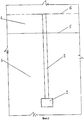
На фиг.1 изображена скважина, пробуренная из подземной горной выработки по рудному телу за пределы его контакта с боковыми породами по высоте участка возможного обрушения боковых пород.Figure 1 shows a well drilled from an underground mine through an ore body beyond its contact with the side rocks along the height of the site of possible collapse of the side rocks.
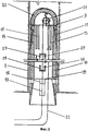
На фиг.2 - верхняя часть взрывораспорного анкера, состоящая из направляющего элемента, соединенного с дополнительным отрезком трубы. Верхняя часть взрывораспорного анкера установлена в устье скважины.Figure 2 - the upper part of the explosive expansion anchor, consisting of a guide element connected to an additional pipe segment. The upper part of the explosive anchor is installed at the wellhead.
На фиг.3 - взрывораспорный анкер после его сборки, установленный в устье скважины,Figure 3 - explosive anchor after assembly, installed at the wellhead,
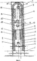
На фиг.4 - взрывораспорный анкер после его сборки, установленный в скважине на участке возможного обрушения боковых пород.Figure 4 - explosive anchor after its assembly, installed in the well at the site of possible collapse of lateral rocks.
На фиг.5 - взрывораспорный анкер после его сборки, установленный в скважине на участке возможного обрушения боковых пород с отрезком детонирующего шнура, первым капсюлем - детонатором мгновенного действия и первой ударно - волновой трубкой.Figure 5 - explosion-proof anchor after its assembly, installed in the well in the area of possible collapse of the side rocks with a detonating cord, the first capsule - instant detonator and the first shock wave tube.
На фиг.6 - скважина перед взрывом с введенным в нее взрывораспорного анкера с отрезком детонирующего шнура, первым капсюлем-детонатором мгновенного действия, первой ударно-волновой трубкой, зарядом взрывчатого вещества, вторым капсюлем-детонатором замедленного действия и второй ударно-волновой трубкой.Figure 6 - well before the explosion with an explosive expansion anchor inserted into it with a detonating cord segment, the first instant detonator capsule, the first shock wave tube, the explosive charge, the second delayed detonator capsule and the second shock wave tube.
На фиг.7 - продольный разрез подземной горной выработки после взрыва, показывающий взрывораспорные анкеры, установленные на участке с возможным обрушением боковых пород и рудное тело, взорванное скважинными зарядами.7 is a longitudinal section of an underground mine after an explosion, showing explosive anchors installed in a site with possible collapse of lateral rocks and an ore body exploded by borehole charges.
Позиции способа установки взрывораспорного анкера по заявляемому изобретения обозначены следующими цифрами:The position of the installation method of explosive anchor according to the claimed invention are indicated by the following numbers:
- 1 - подземная горная выработка;- 1 - underground mining;
- 2 - скважина;- 2 - well;
- 3 - рудное тело;- 3 - ore body;
- 4 - боковые породы;- 4 - lateral rocks;
- 5 - контакт рудного тела с боковыми породами;- 5 - contact of the ore body with the lateral rocks;
- 6 - граница участка возможного обрушения боковых пород;- 6 - boundary of the site of possible collapse of lateral rocks;
- 7 - взрывораспоный анкер;- 7 - explosion-proof anchor;
- 8 - отрезок трубы, размещаемый со стороны устья скважины;- 8 - pipe segment, placed from the side of the wellhead;
- 9 - направляющий элемент, выполненный в виде отрезка трубы с дном овальной формы;- 9 - a guiding element made in the form of a pipe segment with an oval-shaped bottom;
- 10 - дополнительный отрезок трубы;- 10 - an additional segment of the pipe;
- 11 - внешний конус отрезка трубы;- 11 - the outer cone of the pipe segment;
- 12 - внутренний конус отрезка трубы;- 12 - the inner cone of the pipe segment;
- 13 - продольные щели внешнего конуса;- 13 - longitudinal slots of the outer cone;
- 14 - элементы внешнего конуса с выступами;- 14 - elements of the outer cone with protrusions;
- 15 - элементы внешнего конуса без выступов;- 15 - elements of the outer cone without protrusions;
- 16 - отверстия на участке отрезка трубы с внутренним конусом;- 16 - holes in the pipe section with an inner cone;
- 17 - выступ элемента внешнего конуса;- 17 - the protrusion of the element of the outer cone;
- 18 - продольные пазы внутреннего конуса;- 18 - longitudinal grooves of the inner cone;
- 19 - линия, разделяющая внутренние поверхности внутреннего конуса и отрезка трубы;- 19 - a line dividing the inner surface of the inner cone and the pipe section;
- 20 - дно овальной формы направляющего элемента;- 20 - the bottom of the oval shape of the guide element;
- 21 - блок направляющего элемента;- 21 - block guide element;
- 22 - гибкая нить для подъема детонирующего шнура;- 22 - a flexible thread for lifting a detonating cord;
- 23 - зажим для крепления отрезка детонирующего шнура;- 23 - clip for attaching a segment of a detonating cord;
- 24 - отрезок детонирующего шнура;- 24 - a segment of a detonating cord;
- 25 - первый капсюль-детонатор мгновенного действия;- 25 - the first instant detonator capsule;
- 26 - первая ударно-волновая трубка;- 26 - the first shock wave tube;
- 27, 28 - щели на цилиндрических участках отрезков труб;- 27, 28 - cracks in the cylindrical sections of pipe segments;
- 29, 30 - отгибающиеся упоры, образованные щелями, вырезанными на цилиндрических участках отрезков труб;- 29, 30 - folding bumps formed by slots cut in cylindrical sections of pipe segments;
- 31 - герметизатор устья взрывораспорного анкера;- 31 - the mouth seal of the explosive expansion anchor;
- 32 - второй капсюль-детонатор замедленного действия;- 32 - the second delayed-action detonator capsule;
- 33 - вторая ударно-волновая трубка;- 33 - the second shock wave tube;
- 34 - взрывчатое вещество;- 34 - explosive;
- 35 - очистная камера по добыче полезного ископаемого;- 35 - treatment chamber for mining;
- 36 - кровля очистной камеры, представленная боковыми породами;- 36 - the roof of the treatment chamber, represented by lateral rocks;
- 37 - взорванное рудное тело;- 37 - blasted ore body;
- 38 - почва подземной горной выработки.- 38 - soil underground mining.
На чертеже (фиг.1) показана подземная горная выработка 1, скважина 2, рудное тело 3, участок боковых пород 4, контакт 5 рудного тела с боковыми породами, граница 6 участка возможного обрушения боковых пород. Позиции 7÷38 на чертеже (фиг.1) не видны, а показаны на чертеже (фиг.2) - позиции 9÷30, на чертеже (фиг.3) - позиции 7÷-8, на чертеже (фиг.6) - позиции 31÷34, на чертеже (фиг.7) - позиции 35÷38.The drawing (figure 1) shows an
На чертеже (фиг.2) показана верхняя часть взрывораспорного анкера 7, которая установлена в устье скважины 2. Верхняя часть включает дополнительный: отрезок трубы 10, соединенный с направляющим элементом 9, выполненным в виде отрезка трубы, с дном овальной формы. На чертеже (фиг.2) внешний конус 11 отрезка трубы, внутренний конус 12 отрезка трубы, продольные щели 13 на внешнем конусе 11 отрезка трубы, элементы внешнего конуса отрезка трубы с выступами 14, элементы внешнего конуса отрезка трубы без выступов 15, отверстия 16 на участке отрезка трубы с внутренним конусом, выступы 17 элементов внешнего конуса отрезка трубы, продольные пазы 18 внутреннего конуса, линия 19, разделяющая внутренние поверхности внутреннего конуса и отрезка трубы, дно 20 овальной формы направляющего элемента, блок 21 направляющего элемента, гибкая нить 22 для подъема отрезка детонирующего шнура, щели 27, 28 на цилиндрических участках отрезков труб, отгибающиеся упоры 29, 30 щелей на цилиндрических участках труб. Позиции 1÷6, 23÷26, 31÷38 на чертеже (фиг.2) не видны, а показаны на чертеже (фиг.1) - позиции 1÷6, на чертеже (фиг.6) - позиции 23÷26, 31÷34, на чертеже (фиг.7) - позиции 35÷38.The drawing (figure 2) shows the upper part of the
На чертеже (фиг.3) показан собранный взрывораспорный анкер 7, который установлен в устье скважины 2. Верхняя часть взрывораспорного анкера 7 соединена с отрезком трубы 8, устанавливаемым со стороны устья скважины 2. Наименование позиций на чертеже (фиг.3) те же, что и на чертеже (фиг.2). Позиции 1÷6, 23÷26, 31÷38 на чертеже (фиг.2) не видны, а показаны на чертеже (фиг.1) - позиции 1÷6, на чертеже (фиг.6) - позиции 23-26, 31÷34, на чертеже (фиг.7) - позиции 35÷38.The drawing (figure 3) shows the assembled explosion-
На чертеже (фиг.4) показан собранный взрывораспорный анкер 7, который поднят вверх по скважине 2 и установлен на участке возможного обрушения боковых пород 4. Позиции 1÷6, 23÷26, 31÷38 на чертеже (фиг.4) не видны, а показаны на чертеже (фиг.1) - позиции 1÷6, на чертеже (фиг.6) - позиции 23÷26, 31÷34, на чертеже (фиг.7) - позиции 35÷38.The drawing (figure 4) shows the assembled
На чертеже (фиг.5) показан взрыввораспорный анкер 7, установленный в скважине 2 на участке возможного обрушения боковых пород 4 с зажимом 23, отрезком детонирующего шнура 24, первым капсюлем - детонатором мгновенного действия 25 и первой ударно - волновой трубкой 26.. Позиции 1÷4, 31÷38 на чертеже (фиг.5) не видны, а показаны на чертеже (фиг.1) - позиции 1÷4, 31÷34, на чертеже (фиг.7) - позиции 35÷38.The drawing (Fig. 5) shows an
На чертеже (фиг.6) показана скважина 2 перед взрывом с введенным в нее взрывораспорного анкера 7 с отрезком детонирующего шнура 24, первым капсюлем-детонатором мгновенного действия 25, первой ударно-волновой трубкой 26, герметизатором 31, вторым капсюлем-детонатором замедленного действия 32, второй ударно-волновой трубкой 33 и зарядом взрывчатого вещества 34 Позиции 27÷30, 35÷38 на чертеже (фиг.6) не видны, а показаны на чертеже (фиг.5) - позиции 27÷30, на чертеже (фиг.7) - позиции 35÷38.The drawing (Fig.6) shows a well 2 before an explosion with an
На на чертеже (фиг.7) показан продольный разрез подземной горной выработки 1 после взрыва с установленными взрывораспорными анкерами 7 на участке с возможным обрушением боковых пород 4. Очистная камера 35 по добыче полезного ископаемого, кровля 36 очистное камеры 35, представленная боковыми породами, взорванное рудное тело 37, размещенное на почве 38 подземной горной выработки 1. Позиции 1, 3, 5, 8÷34 на чертеже (фиг.7) не видны, а показаны на чертеже (фиг.1) - позиции 1, 3, 5, на чертеже (фиг.3) - позиции 7÷30, на чертеже (фиг.6) - позиции 31÷34.The drawing (Fig. 7) shows a longitudinal section of an
Способ установки взрывораспорного анкера осуществляется следующим образом. Условия применения - пологозалегающее рудное тело мощностью 10.0 м залегает в неустойчивых боковых породах. При добыче руды боковые породы обрушаются и в значительной степени снижают эффективность добычных работ. Высота подземной горной выработки для бурения скважин - 2,5 м. Высота участка,возможного обрушение боковых пород - 4,0 м. Длина взрывораспорного анкера, равная 4,0 м, превышает высоту подземной горной выработки для бурения скважины - 2,5 м. Применяем способ установки взрывораспорного анкера из подземной горной выработки по заявляемому изобретению.The installation method of explosive anchor is as follows. Application conditions - a 10.0 m shallow-lying ore body lies in unstable lateral rocks. During ore mining, lateral rocks collapse and significantly reduce the efficiency of mining operations. The height of the underground mine for drilling is 2.5 m. The height of the area that could collapse lateral rocks is 4.0 m. The length of the explosive anchor equal to 4.0 m exceeds the height of the underground mine for drilling - 2.5 m. We use the installation method of explosive expansion anchor from underground mining according to the claimed invention.
Для этого, из подземной горной выработки 1 бурят скважину 2 глубиной 10,0 м по рудному телу 3, пересекают его контакт 5 с боковыми породами 4 и бурят на участке боковых пород 4 высотой от контакта 5 рудного тела 3 с боковыми породами 4 до границы 6, в пределах которой боковые породы обрушаются. Высота участка возможного обрушения боковых пород составляет 4,0 м. Длину взрывораспорного анкера принимают равной высоте этого участка, то есть 4,0 м.To do this, from
Блок 21 с гибкой нитью 22 для подъема детонирующего шнура устанавливают в направляющий элемент 9, выполненный в виде отрезка трубы с дном 20 овальной формы. Оба конца гибкой нити 22 протягивают через внутреннюю полость по меньшей мере одного дополнительного отрезка трубы 10. Дополнительный отрезок трубы 10 соединяют с направляющим элементом 9 вводом внешнего конуса 11 дополнительного отрезка трубы 10 во внутренний конус 12 направляющего элемента 9. При этом, элементы внешнего конуса с выступами 14 входят в продольные пазы 18 внутреннего конуса 12 направляющего элемента 9, а элементы внешнего конуса без выступов 15 скользят по поверхности внутреннего конуса 12 направляющего элемента 9, приближаясь к линии 19, разделяющей внутренние поверхности внутреннего конуса 12 и отрезка трубы направляющего элемента 9. Продольные щели 13 внешнего конуса 11 дополнительного отрезка трубы 10 снижают жесткость внешнего конуса 11 и облегчают установку выступов 17 в отверстия 16 на участке отрезка трубы направляющего элемента 9.
Направляющий элемент 9, соединенный с дополнительным отрезком трубы 10 вводят в устье скважины 2. Оба конца гибкой нити 22, протянутые через внутреннюю полость дополнительного отрезка трубы 10, пропускают через отрезок трубы 8, размещаемый со стороны устья скважины 2.A
Отрезок трубы 8, размещаемый со стороны устья скважины 2, соединяют с дополнительным отрезком трубы 10 вводом внешнего конуса 11 отрезка трубы 8 во внутренний конус 12 дополнительного отрезка 10. При этом элементы внешнего конуса с выступами 14 входят в продольные пазы 18 внутреннего конуса 12 дополнительного отрезка трубы 10, а элементы внешнего конуса без выступов 15 скользят по поверхности внутреннего конуса 12 дополнительного отрезка трубы 10, приближаясь к линии 19, разделяющей внутренние поверхности внутреннего конуса 12 и дополнительного отрезка трубы 10. Продольные щели 13 внешнего конуса 11 отрезка трубы 8 снижают жесткость внешнего конуса 11 и облегчают установку выступов 17 в отверстия 16 дополнительного отрезка трубы 10.A segment of
Направляющий элемент 9,, соединенный с дополнительным отрезком трубы 10, соединенным с отрезком трубы 8, вводят в устье скважины 2 перемещением вверх на длину отрезка трубы 8.The
Взрывораспорный анкер 7 перемещают по скважине 2 вверх на участок возможного боковых пород 4. Отрезок детонирующего шнура 24 прикрепляют зажимом 23 к гибкой нити 22. К нижнему концу отрезка детонирующего шнура 24 подсоединяют первый капсюль-детонатор мгновенного действия 25 в защищенном от повреждений корпусе с первой ударно-волновой трубкой 26, поднимают и устанавливают внутри взрывораспорного анкера 7.Explosion-
Выведенные из скважины 2 две гибкие нити 22 закрепляют в подземной горной выработке 1, а первую ударно-волновую трубку 26 оставляют свободной.Withdrawn from the
Устанавливают герметизатор 31 устья взрывораспорного анкера, предотвращающий заполнение внутренней полости взрыворасорного анкера 7 взрывчатым веществом 34 при заряжании скважины 2.Install the
Заполняют скважину 2, устанавливая второй капсюль-детонатор 32 замедленного действия с патроном-боевиком и второй ударно-волновой трубкой 33.Fill the
Из скважины 2 выводят: первую ударно-волновую трубку 26, вторую ударно-волновую трубку 33, присоединяют их к одному источнику инициирования первой 26 и второй 33 ударно-волновых трубок, например, к детонирующему шнуру, являющемуся элементом общей схемы взрывной сети массового взрыва и инициируемого электродетонатором.From the
Инициируют первый капсюль-детонатор 25 мгновенного действия и второй капсюль-детонатор 32 замедленного действия, от одного источника инициирования, то есть находящиеся в скважине 2 средства взрывания инициируют за один прием взрывания.The first
В процессе этого приема первым взрывают отрезок детонирующего шнура 24. Образовавшиеся при взрыве высокого давления и температуры газы плотно прижимают стенки отрезков трубы взрывораспорного анкера 7 к стенкам скважины 2, отгибающиеся упоры внедрают в породу при их отгибе, увеличивая несущую способность взрывораспорного анкера 7.In the process of this technique, the detonating
В результате взрыва отрезка детонирующего шнура 24 укрепляют боковые породы 4 на участке возможного их обрушения между контактом 5 рудного тела с боковыми породами и границей 6 этого участка до взрыва взрывчатого вещества в скважине 2.As a result of the explosion of a segment of the detonating
В процессе этого же приема, через 1-2 секунды после инициирования первого капсюля-детонатора 25 мгновенного действия, взрывают второй капсюль-детонатор замедленного действия 32, который взрывает взрывчатое вещество 34 в скважине 2. При этом взрыве дробят рудное тело 3, образуют очистную камеру 35 с кровлей 36 очистной камеры 35 и взорванным рудным телом 37 на почве 38 подземной горной выработки 1.In the same process, 1-2 seconds after the initiation of the first
Образованная кровля 36 является устойчивой и не способна обрушаться, так как боковые породы 4 закреплены установленными взрывораспорными анкерами 7.The formed
Таким образом, взрывораспорные анкеры 7, установленные с опережением взрыва скважинных зарядов, способствуют образованию очистной камеры 35, создавав вместо участка возможного обрушения боковых пород, устойчивую кровлю из боковых пород очистной камеры 35, повышая эффективность добычи полезного ископаемого, В результате достигается технический результат.Thus, explosion-
Оригинальность заявляемого изобретения заключается во введении в скважину взрывораспорного анкера повышенной несущей способности длиною, превышающей размеры поперечного сечения подземной выработки, а также в опережающей установке взрывораспорного анкера относительно взрыва скважинного зарядаThe originality of the claimed invention lies in the introduction into the well of an explosive expansion anchor with an increased bearing capacity of a length exceeding the cross-sectional dimensions of the underground mine, as well as in the advanced installation of an explosive expansion anchor relative to a blast hole explosion
Claims (3)
Priority Applications (1)
| Application Number | Priority Date | Filing Date | Title |
|---|---|---|---|
| RU2012121058/03A RU2498075C1 (en) | 2012-05-22 | 2012-05-22 | Method to install blast expansion anchor |
Applications Claiming Priority (1)
| Application Number | Priority Date | Filing Date | Title |
|---|---|---|---|
| RU2012121058/03A RU2498075C1 (en) | 2012-05-22 | 2012-05-22 | Method to install blast expansion anchor |
Publications (1)
| Publication Number | Publication Date |
|---|---|
| RU2498075C1 true RU2498075C1 (en) | 2013-11-10 |
Family
ID=49683191
Family Applications (1)
| Application Number | Title | Priority Date | Filing Date |
|---|---|---|---|
| RU2012121058/03A RU2498075C1 (en) | 2012-05-22 | 2012-05-22 | Method to install blast expansion anchor |
Country Status (1)
| Country | Link |
|---|---|
| RU (1) | RU2498075C1 (en) |
Cited By (9)
| Publication number | Priority date | Publication date | Assignee | Title |
|---|---|---|---|---|
| CN107268595A (en) * | 2016-04-09 | 2017-10-20 | 河南城建学院 | The many rope anti_floating foundations in soil base spider arm end and its construction method |
| CN107268589A (en) * | 2016-04-09 | 2017-10-20 | 河南城建学院 | One bulb-anchor pole-star member basis and its construction method |
| CN107268594A (en) * | 2016-04-09 | 2017-10-20 | 河南城建学院 | The many rope anti_floating foundations of soil base star centre and arm end and its construction method |
| CN107268592A (en) * | 2016-04-09 | 2017-10-20 | 河南城建学院 | A kind of star member-anchor pole-ball basis and its construction method |
| CN107268657A (en) * | 2016-04-09 | 2017-10-20 | 河南城建学院 | Soil base center and many rope anti_floating foundations of plate angle and its construction method |
| CN107268593A (en) * | 2016-04-09 | 2017-10-20 | 河南城建学院 | Star member-anchor pole-ball basis and its construction method |
| CN107268588A (en) * | 2016-04-09 | 2017-10-20 | 河南城建学院 | A kind of anchor pole-ball-star member basis and its construction method |
| CN107268587A (en) * | 2016-04-09 | 2017-10-20 | 河南城建学院 | Anchor pole-ball-star member basis and its construction method |
| CN107288144A (en) * | 2016-04-09 | 2017-10-24 | 河南城建学院 | Resistance to plucking and antiskid basis and its construction method |
Citations (6)
| Publication number | Priority date | Publication date | Assignee | Title |
|---|---|---|---|---|
| US2573880A (en) * | 1950-09-20 | 1951-11-06 | Temple Velocity Equipment Inc | Explosively actuated anchor for mine roof bolts |
| SU796448A1 (en) * | 1979-03-22 | 1981-01-15 | Кузнецкий Научно-Исследовательскийинститут Строительства Угольныхи Горнорудных Предприятий | Method of placing a tubular anchor |
| SU1437504A1 (en) * | 1986-03-24 | 1988-11-15 | Норильский горно-металлургический комбинат им.А.П.Завенягина | Anchor |
| SU1476147A1 (en) * | 1987-06-23 | 1989-04-30 | Восточный научно-исследовательский горнорудный институт | Tie rod |
| SU1562462A1 (en) * | 1988-04-05 | 1990-05-07 | Shtele Vladimir | Explosion-expanded tubular anchor |
| SU1620640A1 (en) * | 1989-02-23 | 1991-01-15 | Восточный научно-исследовательский горнорудный институт | Yielding bar support |
-
2012
- 2012-05-22 RU RU2012121058/03A patent/RU2498075C1/en not_active IP Right Cessation
Patent Citations (6)
| Publication number | Priority date | Publication date | Assignee | Title |
|---|---|---|---|---|
| US2573880A (en) * | 1950-09-20 | 1951-11-06 | Temple Velocity Equipment Inc | Explosively actuated anchor for mine roof bolts |
| SU796448A1 (en) * | 1979-03-22 | 1981-01-15 | Кузнецкий Научно-Исследовательскийинститут Строительства Угольныхи Горнорудных Предприятий | Method of placing a tubular anchor |
| SU1437504A1 (en) * | 1986-03-24 | 1988-11-15 | Норильский горно-металлургический комбинат им.А.П.Завенягина | Anchor |
| SU1476147A1 (en) * | 1987-06-23 | 1989-04-30 | Восточный научно-исследовательский горнорудный институт | Tie rod |
| SU1562462A1 (en) * | 1988-04-05 | 1990-05-07 | Shtele Vladimir | Explosion-expanded tubular anchor |
| SU1620640A1 (en) * | 1989-02-23 | 1991-01-15 | Восточный научно-исследовательский горнорудный институт | Yielding bar support |
Cited By (9)
| Publication number | Priority date | Publication date | Assignee | Title |
|---|---|---|---|---|
| CN107268595A (en) * | 2016-04-09 | 2017-10-20 | 河南城建学院 | The many rope anti_floating foundations in soil base spider arm end and its construction method |
| CN107268589A (en) * | 2016-04-09 | 2017-10-20 | 河南城建学院 | One bulb-anchor pole-star member basis and its construction method |
| CN107268594A (en) * | 2016-04-09 | 2017-10-20 | 河南城建学院 | The many rope anti_floating foundations of soil base star centre and arm end and its construction method |
| CN107268592A (en) * | 2016-04-09 | 2017-10-20 | 河南城建学院 | A kind of star member-anchor pole-ball basis and its construction method |
| CN107268657A (en) * | 2016-04-09 | 2017-10-20 | 河南城建学院 | Soil base center and many rope anti_floating foundations of plate angle and its construction method |
| CN107268593A (en) * | 2016-04-09 | 2017-10-20 | 河南城建学院 | Star member-anchor pole-ball basis and its construction method |
| CN107268588A (en) * | 2016-04-09 | 2017-10-20 | 河南城建学院 | A kind of anchor pole-ball-star member basis and its construction method |
| CN107268587A (en) * | 2016-04-09 | 2017-10-20 | 河南城建学院 | Anchor pole-ball-star member basis and its construction method |
| CN107288144A (en) * | 2016-04-09 | 2017-10-24 | 河南城建学院 | Resistance to plucking and antiskid basis and its construction method |
Similar Documents
| Publication | Publication Date | Title |
|---|---|---|
| RU2498075C1 (en) | Method to install blast expansion anchor | |
| RU2374604C2 (en) | Self-supported air pipe for blasting and method of rocky ground explosion with its application | |
| CN105735993B (en) | A kind of method of the preventing and treating tight roof type bump based on carbon dioxide explosion | |
| CN102678120B (en) | Method for releasing pressure and removing danger of rock burst | |
| CN103278055B (en) | Roof-cutting pressure relief method in hard-roof deep-hole pre-splitting blasting | |
| JP2017503993A (en) | Explosive tube tube with air gap and bedrock blasting method using the same | |
| CN108132005B (en) | A kind of method of short-delay blasting in medium-length hole upward hole | |
| CN103244180B (en) | Gob-side entry driving surrounding rock control method using remaining small pillars | |
| CN104482816B (en) | A kind of vertical periphery segment algorithm gradient presplit blasting method and device | |
| US8919236B2 (en) | Perforating gun drop sub | |
| CN110067558A (en) | A kind of severe inclined thick coal seam stope drift active workings joint release prevention and treatment impulsion pressure method | |
| WO2006045248A1 (en) | A high-energy gas fracture tool for through-tubing operation | |
| CN102777181A (en) | Method for recovering top coals in advance on full-mechanized caving mining face | |
| CN105387777A (en) | Smooth blasting spaced loading joint-cutting pipe | |
| CN104769213A (en) | Bi-directional shaped charges for perforating a wellbore | |
| RU2519318C1 (en) | Rock destruction device | |
| CN201159620Y (en) | Deep borehole blasting cartridge | |
| CN107270791A (en) | A kind of vertical shaft for mine explosion well completion method | |
| CN106643355A (en) | Forced roof caving method for hugely-thick hard roof in deep coal mine | |
| RU2464421C2 (en) | Extraction of ore using explosion and thermal fragmentation | |
| CN107503728B (en) | Method for improving coal seam permeability by adopting directional water pressure centralized blasting | |
| CN102927863B (en) | A kind of new method of total rock tunnel blasting construction | |
| CN113202474B (en) | Blasting method for protecting eyebrow line by sectional caving method | |
| RU2732554C2 (en) | Method for development of productive formation of well with cumulative charges and device for implementation thereof (embodiments) | |
| CN105804716A (en) | Method for exhausting and mining shale gas in explosive fracturing way and exploding bomb |
Legal Events
| Date | Code | Title | Description |
|---|---|---|---|
| MM4A | The patent is invalid due to non-payment of fees |
Effective date: 20170523 |