RU2492503C1 - Target class recognition method and device for realising said method - Google Patents
Target class recognition method and device for realising said method Download PDFInfo
- Publication number
- RU2492503C1 RU2492503C1 RU2012122163/07A RU2012122163A RU2492503C1 RU 2492503 C1 RU2492503 C1 RU 2492503C1 RU 2012122163/07 A RU2012122163/07 A RU 2012122163/07A RU 2012122163 A RU2012122163 A RU 2012122163A RU 2492503 C1 RU2492503 C1 RU 2492503C1
- Authority
- RU
- Russia
- Prior art keywords
- target
- output
- input
- inputs
- outputs
- Prior art date
Links
- 238000000034 method Methods 0.000 title claims abstract description 14
- 230000005855 radiation Effects 0.000 claims abstract description 5
- 238000001914 filtration Methods 0.000 claims abstract description 4
- 238000001228 spectrum Methods 0.000 claims abstract description 4
- 239000000126 substance Substances 0.000 abstract 1
- 238000001514 detection method Methods 0.000 description 2
- 238000009395 breeding Methods 0.000 description 1
- 230000001488 breeding effect Effects 0.000 description 1
- 238000010586 diagram Methods 0.000 description 1
- 238000005259 measurement Methods 0.000 description 1
- 238000012545 processing Methods 0.000 description 1
- 238000012552 review Methods 0.000 description 1
- 230000001960 triggered effect Effects 0.000 description 1
Landscapes
- Radar Systems Or Details Thereof (AREA)
Abstract
Description
Изобретение относится к системам для обнаружения объектов путем отражения от его поверхности радиоволн и может быть использовано в радиолокации для распознавания класса цели.The invention relates to systems for detecting objects by reflection of radio waves from its surface and can be used in radar to recognize the target class.
Известен способ распознавания, заключающийся в излучении в сторону цели электромагнитной энергии, приеме отраженной от цели электромагнитной энергии, обработки сигналов, распознавании цели по принятому изображению геометрических размеров и конфигурации [1].A known recognition method, which consists in the emission towards the target of electromagnetic energy, the reception of electromagnetic energy reflected from the target, signal processing, target recognition by the received image of geometric dimensions and configuration [1].
Известно устройство для радиолокационного распознавания целей, содержащее антенну, передатчик, приемник, антенный переключатель и канал распознавания, причем передатчик содержит модулятор, генератор СВЧ и первый ключ, где выход модулятора соединен с первым входом первого ключа и первым выходом передатчика, выход генератора СВЧ соединен со вторым входом первого ключа и вторым выходом передатчика, выход первого ключа является третьим выходом передатчика и соединен с первым входом антенного переключателя, второй вход которого соединен с антенной, а выход со входом приемника; канал распознавания содержит последовательно соединенные линию задержки, второй ключ, смеситель, фильтр низких частот и устройство воспроизведения образа цели, причем вход линии задержки является первым входом канала распознавания и соединен с первым выходом передатчика, второй вход смесителя является вторым входом канала распознавания и соединен со вторым выходом передатчика, второй вход второго ключа является третьим входом канала распознавания и соединен со вторым выходом приемника, первый выход передатчика и выход приемника соединены с входами индикатора кругового обзора РЛС [2].A device for radar target recognition, containing an antenna, transmitter, receiver, antenna switch and recognition channel, the transmitter contains a modulator, microwave generator and a first key, where the modulator output is connected to the first input of the first key and the first output of the transmitter, the output of the microwave generator is connected to the second input of the first key and the second output of the transmitter, the output of the first key is the third output of the transmitter and is connected to the first input of the antenna switch, the second input of which is connected to antenna, and the output with the input of the receiver; the recognition channel contains a delay line, a second key, a mixer, a low-pass filter and a target image reproducing device, the input of the delay line being the first input of the recognition channel and connected to the first output of the transmitter, the second input of the mixer being the second input of the recognition channel and connected to the second the output of the transmitter, the second input of the second key is the third input of the recognition channel and is connected to the second output of the receiver, the first output of the transmitter and the output of the receiver are ineny with inputs circular indicator radar review [2].
Недостатком данных способа и устройства является низкая информативность, обусловленная отсутствием возможности распознавания протяженной по скорости цели. На практике подавляющее большинство реальных объектов относится к классу сложных радиолокационных целей.The disadvantage of the data of the method and device is the low information content due to the lack of recognition of a speed-extended target. In practice, the vast majority of real objects belong to the class of complex radar targets.
Погрешности измерения координатных параметров, вызванные шумом цели, начинают возникать, когда физические размеры цели превышают 0,01 величины элемента разрешения по какой-либо координате (Радиолокационные характеристики летательных аппаратов [3].Errors in the measurement of coordinate parameters caused by the noise of the target begin to occur when the physical dimensions of the target exceed 0.01 values of the resolution element in any coordinate (Radar characteristics of aircraft [3].
Наиболее близким к изобретению является способ распознавания протяженной цели, заключающийся в излучении в сторону цели электромагнитной энергии, приеме отраженных от цели сигналов и распознавании цели, проведении узкополосной фильтрации составляющей частоты Доплера спектра отраженного сигнала, определении полосы скоростей сближения с целью ΔV, входящую в полосу пропускания фильтра частоты Доплера ΔFД из выражения ΔV=ΔFД·λ/2, где λ - длина волны излучения, определении полосы частот Доплера ΔFДц занимаемым сигналом, отраженным от цели, определении полосы скоростей движения цели ΔVц занимаемым сигналом, отраженным от цели из выражения ΔVц=ΔFДц·λ/2, определении отношения β=ΔVц/ΔV при этом в случае, если β<0,01, принимают решение о точечной по скорости цели, а в случае, если β>0,01, принимают решение о протяженной по скорости цели [4].Closest to the invention is a method for recognizing an extended target, which consists in emitting electromagnetic energy towards the target, receiving signals reflected from the target and recognizing the target, performing narrow-band filtering of the Doppler frequency component of the reflected signal spectrum, determining the proximity speed band with the target ΔV included in the passband Doppler frequency filter ΔF D from the expression ΔV = ΔF D · λ / 2, where λ is the radiation wavelength, determining the Doppler frequency band ΔF Dts by the occupied signal reflected from the target, determining the target’s speed range ΔV c by the occupied signal reflected from the target from the expression ΔV c = ΔF Dc · λ / 2, determining the ratio β = ΔV c / ΔV in this case, if β <0.01, the decision on speed of the target, and in the case β> 0.01, a decision is made on the target extended in speed [4].
Устройство распознавания протяженной цели, содержит передатчик, антенный переключатель, антенну и приемник, канал распознавания, при этом первый, второй и третий выходы передатчика соединены соответственно с первым входом антенного переключателя, вторым и третьим входами канала распознавания, первый вход которого соединен с выходом приемника, второй вход - выход антенного переключателя соединен с антенной, а выход - со входом приемника, первый выход передатчика и выход приемника соединены со входами индикатора кругового обзора радиолокационной станции, а передатчик содержит модулятор, генератор сверхвысокой частоты (СВЧ) и первый ключ, причем выход модулятора соединен с первым входом первого ключа, второй вход которого соединен с выходом генератора СВЧ, выходы модулятора, генератора СВЧ и первого ключа являются соответственно первым, вторым и третьим выходами передатчика, а канал распознавания содержит последовательно соединенные линию задержки, второй ключ, смеситель, фильтр доплеровских частот, измеритель длительности сигнала, вычислитель и пороговое устройство, при этом первым, вторым и третьим входами канала распознавания являются соотвественно входы смесителя, линии задержки, второй вход второго ключа, первый и второй выходы порогового устройства являются первым и вторым выходами канала распознавания [4].The recognition device for an extended target, contains a transmitter, an antenna switch, an antenna and a receiver, a recognition channel, while the first, second and third outputs of the transmitter are connected respectively to the first input of the antenna switch, the second and third inputs of the recognition channel, the first input of which is connected to the output of the receiver, the second input is the output of the antenna switch is connected to the antenna, and the output is with the input of the receiver, the first output of the transmitter and the output of the receiver are connected to the inputs of the indicator station, and the transmitter contains a modulator, a microwave generator and a first key, and the output of the modulator is connected to the first input of the first key, the second input of which is connected to the output of the microwave generator, the outputs of the modulator, microwave generator and the first key are respectively the first, second and the third outputs of the transmitter, and the recognition channel contains a series-connected delay line, a second key, a mixer, a Doppler frequency filter, a signal duration meter, a calculator and a threshold device, When this first, second and third inputs of detection channels are respectively inputs of the mixer, a delay line, a second input of the second switch, the first and second outputs of the threshold devices are first and second outputs detection channel [4].
Недостатком данных способа и устройства является невозможность распознавания протяженной цели по классу цели: малая, средняя и большая цель.The disadvantage of the data of the method and device is the inability to recognize an extended target by the class of the target: small, medium and large target.
Технической задачей изобретения является расширение информативности за счет обеспечения возможности распознавания протяженной цели по классу цели: малая, средняя и большая цель.An object of the invention is to expand the information content by providing the ability to recognize an extended target by the target class: small, medium and large target.
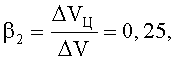
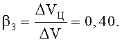
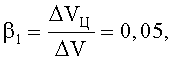
Техническая задача изобретения достигается тем, что в способе распознавания протяженной цели, заключающемся в излучении в сторону цели электромагнитной энергии, приеме отраженных от цели сигналов и распознавании цели, проведении узкополосной фильтрации составляющей частоты Доплера спектра отраженного сигнала, определении полосы скоростей сближения с целью ΔV, входящую в полосу пропускания фильтра частоты Доплера ΔFД из выражения ΔV=ΔFД·λ/2,, где λ - длина волны излучения, определении полосы частот Доплера ΔFДц, занимаемой сигналом, отраженным от цели, определении полосы скоростей движения цели ΔVц, занимаемой сигналом, отраженным от цели из выражения ΔVц=ΔFДц·λ/2, определении отношения β=ΔVц/ΔV, при этом в случае, если β<0,01 принимают решение о точечной, по скорости цели, а в случае, если β>0,01, принимают решение о протяженной, по скорости цели, дополнительно осуществляют селекцию протяженной цели на заданном расстоянии от цели по классу цели в соответствии с выражением β=ΔVц/ΔV, принимают решение, что цель малая в случае, если β≥β1, принимают решение, что цель средняя в случае, если β≥β2, принимают решение, что цель большая в случае, если β≥β3, при этом предлагаемые неравенства однозначно определяют класс цели при следующих значениях величин: 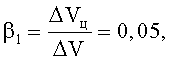


Заявленный способ реализуется в устройстве распознавания протяженной цели, содержащем передатчик, антенный переключатель, антенну и приемник, канал распознавания, при этом первый, второй и третий выходы передатчика соединены соответственно с первым входом антенного переключателя, вторым и третьим входами канала распознавания, первый вход которого соединен с выходом приемника, второй вход-выход антенного переключателя соединен с антенной, а выход - со входом приемника, второй выход передатчика и выход приемника соединены с входами индикатора кругового обзора радиолокационной станции, а передатчик содержит модулятор, генератор сверхвысокой частоты (СВЧ) и ключ, причем выход модулятора соединен с первым входом ключа, второй вход которого соединен с выходом генератора СВЧ, выходы ключа, модулятора и генератора СВЧ и являются соответственно первым, вторым и третьим выходами передатчика, а канал распознавания содержит последовательно соединенные линию задержки, ключ, смеситель, фильтр доплеровских частот, измеритель длительности сигнала, вычислитель и пороговое устройство, при этом первым, вторым и третьим входами канала распознавания являются соответственно второй вход ключа, входы линии задержки и смесителя, а первый и второй выходы порогового устройства являются первым и вторым выходами канала распознавания, дополнительно введены канал селекции протяженных целей, индикатор малая цель, индикатор средняя цель, индикатор большая цель, причем первый, второй и третий входы канала селекции протяженных целей, соединены соответственно с первым выходом передатчика, выходом приемника и вторым выходом канала распознавания, первый, второй и третий выходы канала селекции протяженных целей, соединены соответственно с входами индикаторов малая цель, средняя цель и большая цель, канал селекции протяженных целей содержит элемент ИЛИ, дифференцирующую цепь, сдвиговый регистр, первый, второй, третий и четвертый элементы НЕ, генератор сигналов, первый, второй и третий элементы И, счетчик, первое, второе, третье и четвертое пороговые устройства, первый, второй и третий ключи, задатчик сигналов, при этом первым, вторым и третьим входами канала селекции протяженных целей являются соответственно первый и второй входы элемента ИЛИ, вторые входы второго, третьего и четвертого пороговых устройств, вход дифференцирующей цепи соединен с первым выходом передатчика, а выход соединен со вторыми входами сдвигового регистра и счетчика, выход элемента ИЛИ соединен с первым входом сдвигового регистра, третий вход которого соединен с выходом генератора импульсов, первый и второй выходы сдвигового регистра соединены, через первый элемент НЕ и непосредственно с первым и вторым входами первого элемента И, третий вход которого соединен с выходом генератора импульсов, выход первого элемента И, через первый вход счетчика, соединен со вторым входом первого порогового устройства, второй вход которого соединен с первым выходом задатчика сигналов, выход первого порогового устройства через второй элемент НЕ соединен со вторыми входами первого, второго и третьего ключей, первые входы которых соединены со вторым, третьим и четвертым выходами задатчика сигналов, а выходы данных ключей соединены соответственно с первыми входами второго, третьего и четвертого пороговых устройств, величина порогового значения сигнала для первого порогового устройства устанавливается на первом выходе задатчика в зависимости от заданной дальности до цели, величины пороговых значений сигналов второго, третьего и четвертого пороговых устройств устанавливаются на втором, третьим и четвертом выходах задатчика сигналов, при этом величины пороговых значений сигналов β1; β2; β3; определяются в соответствии со следующими значениями: 
Новыми признаками, обладающими существенными отличиями по способу, является следующая совокупность действий.New features that have significant differences in the method is the following set of actions.
1. Осуществляют селекцию протяженной цели на заданном расстоянии от цели в соответствии с выражением: β=ΔVц/ΔV1. Select an extended target at a given distance from the target in accordance with the expression: β = ΔV c / ΔV
2. Принимают решение, что цель малая в случае, если β≥β1.2. Make a decision that the goal is small if β≥β 1 .
3. Принимают решение, что цель средняя в случае β≥β2.3. Decide that the goal is average in the case of β≥β 2 .
4. Принимают решение, что цель большая в случае β≥β3.4. Decide that the goal is large in the case of β≥β 3 .
Новыми элементами, обладающими существенными отличиями по устройству, являются дополнительно введенные канал селекции протяженной цели, индикатор малая цель, индикатор средняя цель, индикатор большая цель.New elements that have significant differences in the device are the additionally introduced extended target selection channel, the indicator is a small target, the indicator is an average target, and the indicator is a large target.
На чертеже приведена функциональная схема устройства распознавания протяженной цели.The drawing shows a functional diagram of a device for recognition of an extended target.
Устройство распознавания класса цели содержит передатчик 1, антенный переключатель 2, антенну 3, приемник 4, канал 5 распознавания, канал 6 селекции протяженой цели, индикатор 7 малая цель, индикатор 8 средняя цель и индикатор 9 большая цель.The target class recognition device comprises a transmitter 1, an antenna switch 2, an antenna 3, a receiver 4, a recognition channel 5, an extended target selection channel 6, an indicator 7 is a small target, an indicator 8 is an average target, and an indicator 9 is a large target.
Передатчик 1 содержит модулятор 10, генератор 11 СВЧ и ключ 12, при этом выход генератора 11 СВЧ соединен со вторым входом ключа 12, выходы 12 ключа, модулятора 10 и генератора 11 СВЧ, являются соответственно первым, вторым и третьим выходами передатчика 1.The transmitter 1 contains a modulator 10, a microwave generator 11 and a key 12, while the output of the microwave generator 11 is connected to the second input of the key 12, the outputs 12 of the key, the modulator 10 and the microwave generator 11 are the first, second and third outputs of the transmitter 1, respectively.
Канал 5 распознавания содержит последовательно соединенные линию 13 задержки, 14 ключ, смеситель 15, фильтр 16 доплеровских частот, измеритель 17 длительности, вычислитель 18 и пороговое устройство 19, при этом первым, вторым и третьим входами канала 5 распознавания являются соответственно вход линии 13 задержки, вход ключа 14, второй вход смесителя 15, первые и вторые выходы порогового устройства 19, являются соответственно первым и вторым выходами канала 5 распознавания.The recognition channel 5 comprises a delay line 13, 14 key, mixer 15, a Doppler frequency filter 16, a duration meter 17, a calculator 18, and a threshold device 19 connected in series, the first, second, and third inputs of the recognition channel 5 being respectively the input of the delay line 13, the input of the key 14, the second input of the mixer 15, the first and second outputs of the threshold device 19, are respectively the first and second outputs of the recognition channel 5.
Канал 6 селекции протяженных целей содержит элемент ИЛИ 20, дифференцирующую цепь 21, сдвиговый регистр 22, первый 23, второй 24, третий 25 и четвертый 26 элементы НЕ, генератор 27 сигналов, первый 28, второй 29 и третий 30 элементы И, счетчик 31, первое 32, второе 33, третье 34 и четвертое 35 пороговые устройства, первый 36, второй 37 и третий 38 ключи, задатчик 39 сигналов, при этом первым, вторым и третьим входами канала 6 селекции протяженных целей являются первый и второй входы элемента ИЛИ 20, вторые входы второго 33, третьего 34 и четвертого 35 пороговых устройств.Channel 6 selection of extended targets contains an OR element 20, a differentiating circuit 21, a shift register 22, the first 23, the second 24, the third 25 and the fourth 26 elements are NOT, the signal generator 27, the first 28, the second 29 and the third 30 elements And, the counter 31, the first 32, second 33, third 34 and fourth 35 threshold devices, the first 36, second 37 and third 38 keys, a signal setter 39, while the first, second and third inputs of the extended target selection channel 6 are the first and second inputs of the OR element 20, the second inputs of the second 33, third 34 and fourth 35 threshold devices.
При этом первый, второй и третий выходы передатчика 1 соединены соответственно с первым входом антенного переключателя 2 и вторым и третьими входами канала 5 распознавания, второй вход-выход антенного переключателя 2 соединен с выходом-входом антенны 3, выход антенного переключателя 2 соединен с входом приемника 4, выход которого соединен с первым входом канала 5 распознавания и одновременно со вторым входом канала 6 селекции протяженной цели, первый и третий входы которого соединены соответственно с первым 1 выходом передатчика и со вторым выходом канала 5 распознавания, первый, второй и третий выходы канала 6 селекции протяженной цели соединены с входами индикатора 7 малая цель, индикатора 8 средняя цель и индикатора 9 большая цель, вход дифференцирующей цепи 21 соединен с первым выходом передатчика 1, а выход соединен со вторыми входами сдвигового регистра 22 и счетчика 31, выход элемента ИЛИ 20 соединен с первым входом сдвигового регистра 22, третий вход которого соединен с выходом генератора 27 импульсов, первый и второй выходы сдвигового регистра 22 соединены, через первый 23 элемент НЕ и непосредственно, с первым и вторым входами первого 28 элемента И, третий вход которого соединен с выходом генератора 27 импульсов, выход первого 28 элемента И, через первый вход счетчика 31, соединен со вторым входом первого 32 порогового устройства, второй вход которого соединен с первым выходом задатчика 38 сигналов, выход первого 32 порогового устройства соединен со вторыми входами первого 36, второго 37 и третьего 38 ключей, первые входы которых соединены со вторым, третьим и четвертым выходами задатчика 39 сигналов, а выходы данных ключей соединены соответственно с первыми входами второго 33, третьего 34 и четвертого 35 пороговых устройств, выход второго 33 порогового устройства соединен с первым входом второго 29 элемента И, второй и третий входы которого соединены с выходами второго 24 и третьего 25элементов НЕ, выход третьего 34 порогового устройства соединен одновременно со входом второго 24 элемента НЕ и первым входом третьего 30 элемента И, второй вход которого соединен с выходом третьего 25 элемента НЕ, выход четвертого 35 порогового устройства соединен со входом четвертого 26 элемента НЕ, выходы второго 29, третьего 30 элементов И и четвертого 35 порогового устройства являются соответственно первым, вторым и третьим выходами канала 6 селекции протяженных целей.The first, second and third outputs of the transmitter 1 are connected respectively to the first input of the antenna switch 2 and the second and third inputs of the recognition channel 5, the second input-output of the antenna switch 2 is connected to the output-input of the antenna 3, the output of the antenna switch 2 is connected to the input of the receiver 4, the output of which is connected to the first input of the recognition channel 5 and simultaneously with the second input of the extended target selection channel 6, the first and third inputs of which are connected respectively to the first 1 output of the transmitter and to the second the output of the recognition channel 5, the first, second and third outputs of the extended target selection channel 6 are connected to the inputs of the indicator 7 small target, indicator 8 the middle target and indicator 9 large target, the input of the differentiating circuit 21 is connected to the first output of the transmitter 1, and the output is connected to the second the inputs of the shift register 22 and the counter 31, the output of the OR element 20 is connected to the first input of the shift register 22, the third input of which is connected to the output of the pulse generator 27, the first and second outputs of the shift register 22 are connected through the first 23 t NOT and directly, with the first and second inputs of the first 28 And element, the third input of which is connected to the output of the pulse generator 27, the output of the first 28 And element, through the first input of the counter 31, is connected to the second input of the first 32 threshold device, the second input of which is connected with the first output of the signal setter 38, the output of the first 32 threshold device is connected to the second inputs of the first 36, second 37 and third 38 keys, the first inputs of which are connected to the second, third and fourth outputs of the signal setter 39, and the outputs of these keys with connected to the first inputs of the second 33, third 34 and fourth 35 threshold devices, the output of the second 33 threshold device is connected to the first input of the second 29 AND elements, the second and third inputs of which are connected to the outputs of the second 24 and third 25 elements NOT, the output of the third 34 threshold device connected simultaneously with the input of the second 24 element NOT and the first input of the third 30 element AND, the second input of which is connected to the output of the third 25 element NOT, the output of the fourth 35 threshold device is connected to the input of the fourth 26 e ementa NOT outputs of second 29, third 30 and fourth AND gates 35 threshold devices are respectively first, second and third output channel 6 extended breeding purposes.
Пороговые значения сигналов для первого 32, второго 33, третьего 34 и четвертого35 пороговых устройств канала 6 селекции протяженной цели устанавливаются исходя из следующих соображений.The threshold signal values for the first 32, second 33, third 34 and fourth 35 threshold devices of channel 6 for selecting an extended target are set based on the following considerations.
Величина порогового значения сигнала для первого 32 порогового устройства устанавливается на первом выходе задатчика 39 в зависимости от заданной дальности до цели.The threshold value of the signal for the first 32 threshold device is set at the first output of the setter 39 depending on the specified range to the target.
Величины пороговых значений сигналов второго 33, третьего 34 и четвертого 35 пороговых устройств устанавливаются на втором, третьим и четвертом выходах задатчика 39 сигналов, при этом величины пороговых значений сигналов β1; β2; β3; определяются в соответствии со следующими значениями:The values of the threshold values of the signals of the second 33, third 34 and fourth 35 threshold devices are set at the second, third and fourth outputs of the signal generator 39, while the threshold values of the signals β 1 ; β 2 ; β 3 ; are determined in accordance with the following values:
где ΔVц - ширина полосы скоростей движения цели, ΔV ширина полосы скоростей сближения с целью.where ΔV c is the target speed bandwidth, ΔV is the approximation target speed bandwidth.
Определения геометрических размеров целей требует наличие радиолокационной станции с высокой разрешающей способностью по дальности менее 1 м (<1 м). Реализация указанной разрешающей способности возможна либо за счет применения немодулированных импульсных сигналов очень малой длительности либо за счет сигналов с внутриимпульсной модуляцией. Немодулированные сигналы очень малой длительности (единицы - десятки наносекунд) иногда называют сверхширокополосными сигналами (СШПС). Многочастотные РЛС со СШПС обеспечивают разрешающую способность в единицы сантиметров и определения радиолокационных характеристик объектов на удалении до единиц километров [Астанин Л.Ю., Костылев А.А. Методы теоретического и экспериментального нестанционарного рассеяния и излучения электромагнитных волн. - Зарубежная радиоэлектроника, 1981, №9, с.3-37].Determining the geometrical dimensions of targets requires a radar station with high resolution in range of less than 1 m (<1 m). The implementation of this resolution is possible either through the use of unmodulated pulse signals of very short duration or due to signals with intrapulse modulation. Unmodulated signals of very short duration (units - tens of nanoseconds) are sometimes called ultra-wideband signals (UWB). Multi-frequency radars with UWB provide resolution in units of centimeters and determine the radar characteristics of objects at a distance of units of kilometers [Astanin L.Yu., Kostylev A.A. Methods of theoretical and experimental non-stationary scattering and radiation of electromagnetic waves. - Foreign Radio Electronics, 1981, No. 9, p.3-37].
Указанная дальность действия является приемлемой для распознавания целей на конечном участке радиолокационными головками самонаведения авиационных управляемых ракет. Ширина полосы отраженного сигнала зависит от класса цели: малая цель (5 м), средняя цель(25) м, большая цель (40) м. Данное обстоятельство является информативным признаком для определения класса цели на малых дальностях до цели.The specified range is acceptable for target recognition at the final section of the radar homing aircraft guided missiles. The bandwidth of the reflected signal depends on the class of the target: small target (5 m), medium target (25) m, large target (40) m. This fact is an informative sign for determining the class of the target at short distances to the target.
Устройство функционирует следующим образом.The device operates as follows.
Отраженный от движущейся цели сигнал поступает на вход антенны 3 и через антенный переключатель 2, приемник 4 и второй 10 ключ поступает на первый вход смесителя 11. На второй вход смесителя 11 поступает сигнал с выхода генератора 7 СВЧ, таким образом, на выходе смесителя 11 получается сигнал на частоте Доплера. Этот сигнал поступает через фильтр 12 доплеровских частот на вход измерителя 13 длительности, на выходе которого формируется сигнал, пропорциональный длительности сигнала, отраженного от цели. Данный сигнал поступает на вход вычислителя 14, на выходе которого формируется сигнал, пропорциональный β=ΔV/ΔVц, который поступает на вход порогового устройства 15, где сравнивается с порогом, равным 0,01. При превышении порога выдается сигнал «протяженная», в противоположном случае выдается сигнал «точечная». Данные сигналы являются выходными сигналами канала 5 распознавания.The signal reflected from the moving target is fed to the input of antenna 3 and through the antenna switch 2, receiver 4 and second 10, the key is fed to the first input of mixer 11. The second input of mixer 11 receives a signal from the output of microwave generator 7, thus, at the output of mixer 11 signal at the Doppler frequency. This signal is transmitted through a filter 12 of Doppler frequencies to the input of the duration meter 13, the output of which is a signal proportional to the duration of the signal reflected from the target. This signal is fed to the input of the calculator 14, at the output of which a signal is generated proportional to β = ΔV / ΔV c , which is fed to the input of the threshold device 15, where it is compared with a threshold of 0.01. When the threshold is exceeded, a “extended” signal is issued; in the opposite case, a “point” signal is issued. These signals are the output signals of the recognition channel 5.
Канал 6 селекции протяженных целей предназначен для определения класса целей: малая, средняя и большая цель.Channel 6 selection of long targets is designed to determine the class of goals: small, medium and large target.
На первый, второй и третий входы канала селекции протяженных целей поступают сигналы с первого выхода передатчика 1, выхода приемника 4 и со второго выхода канала 5 распознавания, при этом сигналы поступают соответственно на первый и второй входы элемента ИЛИ 20, вторые входы второго 33, третьего 34 и четвертого 35 пороговых устройств.The first, second and third inputs of the selection channel for extended targets receive signals from the first output of the transmitter 1, the output of the receiver 4 and from the second output of the recognition channel 5, while the signals are received respectively at the first and second inputs of the OR element 20, the second inputs of the second 33, third 34 and fourth 35 threshold devices.
При включении передатчика 1, сигнал с его первого выхода поступает на вход дифференцирующей цепи 21, с выхода которой сигнал обнуления поступает на вторые входы сдвигового регистра 22 и счетчика 31.When the transmitter 1 is turned on, the signal from its first output goes to the input of the differentiating circuit 21, from the output of which the zeroing signal goes to the second inputs of the shift register 22 and counter 31.
С выхода элемента ИЛИ 20 сигнал поступает на первый вход сдвигового регистра 22, на третий вход которого поступает сигнал с выхода генератора 27 импульсов.From the output of the OR element 20, the signal is fed to the first input of the shift register 22, the third input of which receives a signal from the output of the pulse generator 27.
С первого и второго выхода сдвигового регистра 22 сигналы поступают через первый 23 элемент НЕ и непосредственно на первый и второй входы первого 28 элемента И, на третий вход которого поступает сигнал с выхода генератора 27 импульсов.From the first and second output of the shift register 22, the signals are supplied through the first 23 element NOT and directly to the first and second inputs of the first 28 element And, the third input of which receives a signal from the output of the pulse generator 27.
С выхода первого 28 элемента И сигнал, соответствующий дальности до цели поступает через первый вход счетчика 31, на второй вход первого 32 порогового устройства, на второй вход которого поступает сигнал с первого выхода задатчика 38 сигналов.From the output of the first 28 AND element, the signal corresponding to the range to the target enters through the first input of the counter 31, to the second input of the first 32 threshold device, the second input of which receives the signal from the first output of the signal setter 38.
В момент достижения текущей дальности заданного значения сигнал с выхода первого 32 порогового устройства снимается, при этом с выхода второго 24 элемента НЕ сигнал поступает на вторые входы первого 36, второго 37 и третьего 38 ключей, на первые входы которых поступают сигналы со второго, третьего и четвертого выходов задатчика 38 сигналов.At the moment of reaching the current range of the set value, the signal from the output of the first 32 threshold device is removed, while the output of the second 24 elements is NOT the signal goes to the second inputs of the first 36, second 37 and third 38 keys, the first inputs of which receive signals from the second, third and the fourth outputs of the setter 38 signals.
С выходов данных ключей сигналы различного уровня поступают соответственно на первые входы второго 33, третьего 34 и четвертого 35 пороговых устройств.From the outputs of these keys, signals of various levels are supplied respectively to the first inputs of the second 33, third 34 and fourth 35 threshold devices.
В зависимости от класса цели в случае значения β≥β1 происходит срабатывания второго 33 порогового устройства и сигнал поступает на первый вход второго 29 элемента И, на второй и третий входы которого поступают сигналы с выхода второго 24 и третьего 25 элементов НЕ, обеспечивая тем самым прохождения сигнала на вход индикатора 7 малой цели.Depending on the target class, in the case of β≥β 1 , the second 33 threshold device is triggered and the signal is supplied to the first input of the second 29 AND elements, the second and third inputs of which receive signals from the output of the second 24 and third 25 NOT elements, thereby signal passing to the input of the indicator 7 of the small target.
В случае если β≥β2, сигнал с выхода третьего 34 порогового устройства поступает на первый вход третьего 30 элемента И, на второй вход которого поступает сигнал с выхода третьего 25 элемента НЕ, обеспечивая тем самым прохождения сигнала на вход индикатора 8 средней цели.If β≥β 2 , the signal from the output of the third 34 threshold device is fed to the first input of the third 30 element AND, the second input of which receives the signal from the output of the third 25 element NOT, thereby ensuring the passage of the signal to the input of indicator 8 of the average target.
В случае если значения β≥β3, то сигнал с выхода четвертого 35 порогового устройства поступает на вход индикатора 9 большая цель.If the value β≥β 3 , then the signal from the output of the fourth 35 threshold device is fed to the input of the indicator 9 is a big target.
ИСТОЧНИКИ ИНФОРМАЦИИINFORMATION SOURCES
1. Патент США №3978480, кл. G01S 9/00, 1974 г.1. US patent No. 3978480, CL. G01S 9/00, 1974
2. Небабин В.Г., Сергеев В.В. Методы и техника радиолокационного распознавания. - М.: Радио и связь, 1984, с.36.2. Nebabin V.G., Sergeev V.V. Methods and techniques of radar recognition. - M .: Radio and communications, 1984, p. 36.
3. М.Е. Варганов, Ю.С. Зиновьев, Л.Ю. Астанин и др. Под ред. Л.Т. Тучкова. Радиолокационные характеристики летательных аппаратов. - М.: Радио и связь, 1985. - 236 с., ил. с.17-18.3. M.E. Varganov, Yu.S. Zinoviev, L.Yu. Astanin et al. Ed. L.T. Tuchkova. Radar characteristics of aircraft. - M .: Radio and communications, 1985 .-- 236 p., Ill. p.17-18.
4. Винокуров В.И., Винокуров Д.В., патент РФ №2359285 от 20.06.2009 г., МПК G01S/53.4. Vinokurov V.I., Vinokurov D.V., RF patent No. 2359285 dated 06/20/2009, IPC G01S / 53.
Claims (2)


Priority Applications (1)
| Application Number | Priority Date | Filing Date | Title |
|---|---|---|---|
| RU2012122163/07A RU2492503C1 (en) | 2012-05-23 | 2012-05-23 | Target class recognition method and device for realising said method |
Applications Claiming Priority (1)
| Application Number | Priority Date | Filing Date | Title |
|---|---|---|---|
| RU2012122163/07A RU2492503C1 (en) | 2012-05-23 | 2012-05-23 | Target class recognition method and device for realising said method |
Publications (1)
| Publication Number | Publication Date |
|---|---|
| RU2492503C1 true RU2492503C1 (en) | 2013-09-10 |
Family
ID=49165003
Family Applications (1)
| Application Number | Title | Priority Date | Filing Date |
|---|---|---|---|
| RU2012122163/07A RU2492503C1 (en) | 2012-05-23 | 2012-05-23 | Target class recognition method and device for realising said method |
Country Status (1)
| Country | Link |
|---|---|
| RU (1) | RU2492503C1 (en) |
Cited By (1)
| Publication number | Priority date | Publication date | Assignee | Title |
|---|---|---|---|---|
| RU2667516C1 (en) * | 2017-10-23 | 2018-09-21 | Акционерное общество "НИИ измерительных приборов - Новосибирский завод имени Коминтерна" (АО "НПО НИИИП-НЗиК") | Method of detecting radar objects |
Citations (6)
| Publication number | Priority date | Publication date | Assignee | Title |
|---|---|---|---|---|
| US4647931A (en) * | 1984-11-29 | 1987-03-03 | Rca Corporation | Dual frequency identification system |
| RU2099736C1 (en) * | 1996-05-29 | 1997-12-20 | Военная академия противовоздушной обороны сухопутных войск Российской Федерации | Target identifier |
| RU2261476C1 (en) * | 2004-01-26 | 2005-09-27 | Военный университет связи | Method for recognition of radio signals |
| US7154433B1 (en) * | 2003-01-16 | 2006-12-26 | The United States Of America As Represented By The Secretary Of The Army | Method and device for the detection and track of targets in high clutter |
| RU2359285C1 (en) * | 2007-12-04 | 2009-06-20 | Владимир Иванович Винокуров | Recognition method of extended target as to velocity and device for realisation thereof |
| RU2449309C1 (en) * | 2011-02-16 | 2012-04-27 | Василий Васильевич Ефанов | Abstract |
-
2012
- 2012-05-23 RU RU2012122163/07A patent/RU2492503C1/en active
Patent Citations (6)
| Publication number | Priority date | Publication date | Assignee | Title |
|---|---|---|---|---|
| US4647931A (en) * | 1984-11-29 | 1987-03-03 | Rca Corporation | Dual frequency identification system |
| RU2099736C1 (en) * | 1996-05-29 | 1997-12-20 | Военная академия противовоздушной обороны сухопутных войск Российской Федерации | Target identifier |
| US7154433B1 (en) * | 2003-01-16 | 2006-12-26 | The United States Of America As Represented By The Secretary Of The Army | Method and device for the detection and track of targets in high clutter |
| RU2261476C1 (en) * | 2004-01-26 | 2005-09-27 | Военный университет связи | Method for recognition of radio signals |
| RU2359285C1 (en) * | 2007-12-04 | 2009-06-20 | Владимир Иванович Винокуров | Recognition method of extended target as to velocity and device for realisation thereof |
| RU2449309C1 (en) * | 2011-02-16 | 2012-04-27 | Василий Васильевич Ефанов | Abstract |
Cited By (1)
| Publication number | Priority date | Publication date | Assignee | Title |
|---|---|---|---|---|
| RU2667516C1 (en) * | 2017-10-23 | 2018-09-21 | Акционерное общество "НИИ измерительных приборов - Новосибирский завод имени Коминтерна" (АО "НПО НИИИП-НЗиК") | Method of detecting radar objects |
Similar Documents
| Publication | Publication Date | Title |
|---|---|---|
| KR102186191B1 (en) | Radar sensing with interference suppression | |
| KR101135982B1 (en) | Synchronization method of radar systems for the rejection of interference in FMCW radars | |
| US9933518B2 (en) | FMCW radar having distance range graduation | |
| CN108415010B (en) | Radar multi-target detection method based on trapezoidal LFMCW modulation | |
| CN102947725B (en) | radar device | |
| KR20190096291A (en) | Rader sensing with phase correction | |
| US20230341511A1 (en) | Detection of interference-induced perturbations in fmcw radar systems | |
| CN106199582A (en) | The method being applied to the two-frequency CW radar human body locating and tracking of indoor | |
| CN104635216A (en) | Representative value-based FMCW radar system and method therefore for detecting target | |
| EP1802995B1 (en) | Improved wideband radar | |
| RU2586078C2 (en) | Single-position passive radioelectronic system for determining horizontal coordinates, target motion elements and kilometric attenuation coefficient of electromagnetic radiation of target | |
| RU2449309C1 (en) | Abstract | |
| RU2492503C1 (en) | Target class recognition method and device for realising said method | |
| RU2608551C1 (en) | Pulse-doppler airborne radar station operating method during detecting of aerial target, radio reconnaissance station carrier | |
| KR101634455B1 (en) | Radar using linear frequency modulation signal and noise signal, and method for controlling the same | |
| Kaminski et al. | K-band FMCW radar module with interferometic capability for industrial applications | |
| EP4261564A1 (en) | Unambiguous and accurate velocity estimation by frequency-modulated radars | |
| RU2359285C1 (en) | Recognition method of extended target as to velocity and device for realisation thereof | |
| JPH06123772A (en) | Encoded pulse doppler radar system | |
| RU2410713C2 (en) | Method of detecting range-extended target and device for realising said method | |
| RU2492501C1 (en) | Target class recognition method and device for realising said method | |
| RU2221258C1 (en) | Procedure to measure range to several targets by pulse doppler radars with medium pulse repetition rate | |
| RU2483320C1 (en) | Target recognition method and device for realising said method | |
| JP2013113723A (en) | Radar system | |
| RU2580507C2 (en) | Radar method and doppler radar with transmitter for implementation thereof |