RU2477771C2 - Support unit with adjustable trimming pads for electric pit excavator - Google Patents
Support unit with adjustable trimming pads for electric pit excavator Download PDFInfo
- Publication number
- RU2477771C2 RU2477771C2 RU2008136319/03A RU2008136319A RU2477771C2 RU 2477771 C2 RU2477771 C2 RU 2477771C2 RU 2008136319/03 A RU2008136319/03 A RU 2008136319/03A RU 2008136319 A RU2008136319 A RU 2008136319A RU 2477771 C2 RU2477771 C2 RU 2477771C2
- Authority
- RU
- Russia
- Prior art keywords
- specified
- tube
- main body
- receiving
- eccentric
- Prior art date
Links
Images


Classifications
-
- E—FIXED CONSTRUCTIONS
- E02—HYDRAULIC ENGINEERING; FOUNDATIONS; SOIL SHIFTING
- E02F—DREDGING; SOIL-SHIFTING
- E02F3/00—Dredgers; Soil-shifting machines
- E02F3/04—Dredgers; Soil-shifting machines mechanically-driven
- E02F3/28—Dredgers; Soil-shifting machines mechanically-driven with digging tools mounted on a dipper- or bucket-arm, i.e. there is either one arm or a pair of arms, e.g. dippers, buckets
- E02F3/30—Dredgers; Soil-shifting machines mechanically-driven with digging tools mounted on a dipper- or bucket-arm, i.e. there is either one arm or a pair of arms, e.g. dippers, buckets with a dipper-arm pivoted on a cantilever beam, i.e. boom
- E02F3/304—Dredgers; Soil-shifting machines mechanically-driven with digging tools mounted on a dipper- or bucket-arm, i.e. there is either one arm or a pair of arms, e.g. dippers, buckets with a dipper-arm pivoted on a cantilever beam, i.e. boom with the dipper-arm slidably mounted on the boom
-
- E—FIXED CONSTRUCTIONS
- E02—HYDRAULIC ENGINEERING; FOUNDATIONS; SOIL SHIFTING
- E02F—DREDGING; SOIL-SHIFTING
- E02F3/00—Dredgers; Soil-shifting machines
- E02F3/04—Dredgers; Soil-shifting machines mechanically-driven
- E02F3/627—Devices to connect beams or arms to tractors or similar self-propelled machines, e.g. drives therefor
Abstract
Description
ПРЕДПОСЫЛКИ ИЗОБРЕТЕНИЯBACKGROUND OF THE INVENTION
Настоящее изобретение относится к экскаваторам, а более точно, к экскаваторам, имеющим ковш для выкапывания земляного материала. Более точно, настоящее изобретение относится к опорным блокам, которые поддерживают рукоять, или рычаг ковша.The present invention relates to excavators, and more specifically, to excavators having a bucket for digging earth material. More specifically, the present invention relates to support blocks that support a handle, or bucket arm.
Существует много известных устройств для перемещения земли или подобных им устройств. В типичном оборудовании для перемещения земли или экскаваторах предшествующего уровня техники используется ковш или лопата, находящиеся на конце выполненного с возможностью перемещения рычага, для того, чтобы зачерпывать земляной материал из горизонтальных или вертикальных пластов. Для того чтобы вкапываться в разрабатываемую поверхность, ковш обычно оснащен острыми зубьями. Кроме того, ковш содержит полость для сбора удаляемого таким образом материала. Когда земляной материал находится внутри ковша, рычаг обычно перемещается в другое место для переноса материала. Материал обычно выгружается в самосвал, на транспортер или просто на другую кучу материала.There are many known devices for moving the earth or similar devices. Typical earth moving equipment or prior art excavators use a bucket or shovel at the end of a movable arm to scoop up earth material from horizontal or vertical layers. In order to dig into the surface being developed, the bucket is usually equipped with sharp teeth. In addition, the bucket contains a cavity for collecting material thus removed. When the earthen material is inside the bucket, the lever usually moves to another location for material transfer. Material is usually unloaded into a dump truck, onto a conveyor, or simply onto another pile of material.
В крупных электрических канатных экскаваторах для производства горных работ используется копающее приспособление, содержащее неподвижную стрелу и конструкцию, представляющую собой комбинацию из рукояти и ковша, которая установлена на стреле и которая активно проталкивается и поднимается в пласт для наполнения ковша. Как показано на фиг.2, рукоять 26 содержит две стойки 68, которые проходят на каждой стороне стрелы 22. Рукоять 26 имеет зубчатую рейку 62, прикрепленную к нижней части каждой стойки 68. Горизонтально через стрелу 22 также установлен вал 66 механизма загрузки. К валу 66 механизма загрузки шлицами 74 прикреплены два зубчатых колеса 70. Расположенная на стойках 68 рукояти рейка 62 зацепляет шлицы 74 зубчатого колеса. Электродвигатель и передаточный механизм (не показаны) вращают вал механизма загрузки и зубчатые колеса, заставляя тем самым рукоять и зубчатую рейку ползти и перемещаться от стрелы. На валу 66 механизма загрузки установлены два опорных блока 78, и они используются для удержания рукояти 26 в надлежащем положении во время работы экскаватора.Large electric wireline excavators for mining use a digging device containing a fixed boom and a structure that is a combination of a handle and a bucket that is mounted on the boom and that is actively pushed and lifted into the reservoir to fill the bucket. As shown in FIG. 2, the
Во время работы рукоять испытывает усилия в вертикальном и горизонтальном направлениях. Вертикальная сила является результатом раздвигающего усилия между находящейся на рукояти зубчатой рейкой и зубчатым колесом напорного механизма, а также от нагрузок, возникающих при копании. Горизонтальная сила возникает вследствие раскачивания машины, копательных нагрузок и вследствие инерции. Назначение опорных блоков состоит в том, чтобы выдерживать эти силы и удерживать рукоять в нужном положении.During operation, the handle experiences forces in the vertical and horizontal directions. The vertical force is the result of the spreading force between the gear rack located on the handle and the pressure gear gear, as well as from the loads that arise when digging. Horizontal force occurs due to rocking of the machine, digging loads and due to inertia. The purpose of the support blocks is to withstand these forces and hold the handle in position.
Для наилучшей работы между рукоятью и опорным блоком должен быть только малый зазор. В идеальном случае этот зазор имеет величину между 0,3175 см (0,125 дюйма) и 0,635 см (0,25 дюйма). Если зазор увеличивается еще больше, то система начинает испытывать две проблемы. Во-первых, зазоры между составными частями способствуют большим ударным нагрузкам во время движения этих частей. Во-вторых, большой зазор на верхней части рукояти позволяет расположенной на рукояти зубчатой рейке и зубчатому колесу напорного механизма отделяться друг от друга. Это сильно увеличивает нагрузку на зубья передачи, приводя к поломанным зубьям передачи, неровной работе и повышенному шуму.For best performance, there should be only a small gap between the handle and the support block. Ideally, this gap is between 0.3175 cm (0.125 in.) And 0.635 cm (0.25 in.). If the gap increases even more, then the system begins to experience two problems. Firstly, the gaps between the components contribute to large shock loads during the movement of these parts. Secondly, a large gap on the upper part of the handle allows the gear rack located on the handle and the pressure gear gear to separate from each other. This greatly increases the load on the gear teeth, resulting in broken gear teeth, uneven operation and increased noise.
В то время как опорный блок обеспечивает опору для рукояти, рукоять часто проталкивается вперед или отводится назад для того, чтобы углубляться в пласт или для поворота экскаватора. Относительное движение между компонентами вызывает износ на поверхностях опорного блока, которые находятся в соприкосновении с рукоятью. Опорные блоки представляют собой крупные конструкции; следовательно, невыгодно заменять опорный блок целиком из-за его износа на паре поверхностей. По этой причине часть опорного блока составляют сменные изнашивающиеся накладки. Заменить изнашивающиеся накладки гораздо менее затратно и более просто, чем целый опорный блок. После того как изнашивающиеся накладки достигают определенной толщины, их выбрасывают и устанавливают новые. Это сохраняет целостность опорных блоков.While the support block provides support for the handle, the handle is often pushed forward or pulled back to deepen into the formation or to rotate the excavator. The relative movement between the components causes wear on the surfaces of the support block, which are in contact with the handle. Support blocks are large structures; therefore, it is not advantageous to replace the entire support block due to wear on a pair of surfaces. For this reason, replaceable wear pads make up a part of the support block. Replacing wear pads is much less costly and simpler than a complete support block. After the wear pads reach a certain thickness, they are discarded and new ones are installed. This preserves the integrity of the support blocks.
Изнашивающиеся накладки для опорных блоков необходимо регулировать на постоянной основе для поддержания надлежащего зазора между компонентами. Вместо того чтобы выбрасывать изнашивающиеся накладки при каждой регулировке, их переустанавливают для увеличения их срока службы. Между изнашивающимися накладками и опорным блоком устанавливают металлические прокладки 164 и 168, как показано на фиг.3, для поддержания надлежащего рабочего зазора. Эта процедура регулирования зазора работает, но требует времени и является трудной. Прокладки большие, но при этом очень тонкие, что затрудняет обращение с ними. К тому же неудобно работать между рукоятью и опорным блоком. Эта область покрыта смазкой и имеет слабый доступ, а узкие проходы, используемые для достижения этой области, не могут обеспечить идеальный доступ к изнашивающимся накладкам. Так как регулирование изнашивающихся накладок затруднено, то его зачастую не выполняют, или же выполняют не так часто, как это нужно.Wear pads for support blocks need to be adjusted on an ongoing basis to maintain proper clearance between components. Instead of discarding wearing pads with each adjustment, they are reinstalled to increase their service life. Between the wear plates and the support block,
СУЩНОСТЬ ИЗОБРЕТЕНИЯSUMMARY OF THE INVENTION
Одна из целей настоящего изобретения состоит в создании опорного блока с более легким способом регулирования изнашивающихся накладок путем снижения времени, необходимого для осуществления регулирования.One of the objectives of the present invention is to provide a support block with an easier way to regulate wearing pads by reducing the time required for regulation.
Другая цель настоящего изобретения состоит в создании регулирующего опорного блока, который выполняет ту же самую функцию, что и существующие опорные блоки, но не использует регулировочные прокладки и имеет потенциальную возможность для снижения времени технического обслуживания на регулирование зазоров между компонентами.Another objective of the present invention is to provide an adjustment support block that performs the same function as existing support blocks, but does not use shims and has the potential to reduce maintenance time for adjusting the gaps between the components.
Еще одна цель настоящего изобретения состоит в создании регулирующего опорного блока, который может иметь значительное положительное влияние на срок службы расположенной на рукояти зубчатой рейки и срок службы зубчатого колеса, расположенного на валу механизма загрузки.Another objective of the present invention is to provide a regulatory support block, which can have a significant positive effect on the service life of the gear rack located on the handle and the service life of the gear located on the shaft of the loading mechanism.
Согласно этому изобретению, предусмотрен опорный блок, содержащий основной корпус, имеющий отверстие для вала механизма загрузки, проходящее сквозь нижний конец основного корпуса, и отверстие для эксцентрикового пальца, расположенное в верхнем конце основного корпуса, эксцентриковый палец, вставленный в отверстие для эксцентрикового пальца, расположенное в верхнем конце основного корпуса, и опору изнашивающихся накладок. Опора изнашивающихся накладок имеет отверстие для приема пальца, при этом эксцентриковый палец помещен в отверстие для приема пальца. Изнашивающиеся накладки установлены на нижнем конце опоры изнашивающихся накладок и выполнены упирающимися в верхнюю часть рукояти ковша.According to this invention, there is provided a support block comprising a main body having an opening for the shaft of the loading mechanism extending through the lower end of the main body, and an eccentric pin hole located at the upper end of the main body, an eccentric pin inserted in the eccentric finger hole located at the upper end of the main body, and the support of the wear pads. The wear pad bearing has a hole for receiving a finger, while the eccentric finger is placed in the hole for receiving a finger. Wear pads are mounted on the lower end of the support of the wear pads and are made abutting against the upper part of the bucket handle.
В настоящем изобретении также предусмотрен опорный блок, содержащий основной корпус, имеющий верхний конец и нижний конец, при этом основной корпус имеет отверстие для вала механизма загрузки, проходящее сквозь нижний конец основного корпуса. Опорный блок также имеет отверстие для приема трубки в основном корпусе, расположенное между верхним концом основного корпуса и нижним концом основного корпуса, и трубку, вставленную в отверстие для приема трубки. Также имеется приспособление для выдвижения трубки, приспособление для закрепления трубки в отверстии для приема трубки и изнашивающаяся накладка, установленная на конце трубки.The present invention also provides a support block comprising a main body having an upper end and a lower end, the main body having an opening for a shaft of the loading mechanism extending through the lower end of the main body. The support unit also has a hole for receiving the tube in the main body, located between the upper end of the main body and the lower end of the main body, and a tube inserted into the hole for receiving the tube. There is also a device for extending the tube, a device for fixing the tube in the hole for receiving the tube and a wear pad mounted on the end of the tube.
Специалистам будут очевидны другие характерные признаки и преимущества изобретения, при внимательном изучении ими последующего подробного описания, формулы изобретения и чертежей, на которых одинаковые номера позиций использованы для обозначения одинаковых деталей.Other characteristic features and advantages of the invention will be apparent to those skilled in the art, upon careful study of the following detailed description, claims and drawings, in which the same reference numbers are used to denote the same details.
КРАТКОЕ ОПИСАНИЕ ЧЕРТЕЖЕЙBRIEF DESCRIPTION OF THE DRAWINGS
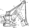
На фиг.1 показан вертикальный вид сбоку экскаватора, иллюстрирующий вариант выполнения настоящего изобретения.1 is a vertical side view of an excavator illustrating an embodiment of the present invention.
На фиг.2 показан поперечный разрез приводного напорного механизма, состоящего из опорного блока и реечной передачи, показанного на фиг.1, взятый вдоль линии «2-2», изображенной на фиг.1.Figure 2 shows a cross section of a drive pressure mechanism, consisting of a support block and a rack and pinion transmission, shown in figure 1, taken along the line "2-2", shown in figure 1.
На фиг.3 показан вид в аксонометрии опорного блока уровня техники.Figure 3 shows a perspective view of a support block of the prior art.
На фиг.4 показан вид в аксонометрии предложенного опорного блока.Figure 4 shows a perspective view of the proposed support block.
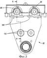
На фиг.5 показан вид сбоку опорного блока, показанного на фиг.4.Figure 5 shows a side view of the support block shown in figure 4.
На фиг.6 показан поперечный разрез опорного блока, показанного на фиг.5, сделанный вдоль линии «6-6», изображенной на фиг.5.Figure 6 shows a cross section of the support block shown in figure 5, made along the line "6-6" shown in figure 5.
На фиг.7 показан вид в аксонометрии задней части опорного блока, показанного на фиг.4.Figure 7 shows a perspective view of the rear of the support block shown in figure 4.
Перед тем как варианты выполнения изобретения будут рассмотрены более подробно, следует подчеркнуть, что изобретение при его применении не ограничено элементами конструкции и расположением составных частей, изложенных в последующем подробном описании или проиллюстрированных на чертежах. Изобретение может иметь другие варианты выполнения и может быть применено на практике или осуществлено различными способами. Также следует понимать, что фразеология и терминология, использованные в настоящем документе, приняты с целью описания и не должны рассматриваться как ограничивающие. Употребление терминов «включающий» и «содержащий», а также их вариантов, использованных в данном документе, предназначено для того, чтобы охватывать перечисленные после них элементы и их эквиваленты, а также дополнительные элементы и их эквиваленты. Употребление термина «состоящий из» и его вариантов в данном документе предназначено для того, чтобы охватывать только элементы, перечисленные после него, и их эквиваленты.Before embodiments of the invention will be discussed in more detail, it should be emphasized that the invention in its application is not limited to structural elements and the location of the components set forth in the following detailed description or illustrated in the drawings. The invention may have other embodiments and may be practiced or practiced in various ways. It should also be understood that the phraseology and terminology used herein is for the purpose of description and should not be construed as limiting. The use of the terms “including” and “comprising”, as well as their variants used in this document, is intended to cover the elements listed after them and their equivalents, as well as additional elements and their equivalents. The use of the term “consisting of” and its variants in this document is intended to cover only the elements listed after it and their equivalents.
ПОДРОБНОЕ ОПИСАНИЕ ПРЕДПОЧТИТЕЛЬНЫХ ВАРИАНТОВ ВЫПОЛНЕНИЯ ИЗОБРЕТЕНИЯDETAILED DESCRIPTION OF THE PREFERRED EMBODIMENTS
На фиг.1 изображен экскаватор 10. Следует понимать, что настоящее изобретение может использоваться в других известных в данной области техники экскаваторах, и экскаватор 10 выполнен только в качестве примера такого экскаватора. Экскаватор 10 содержит раму 14, являющуюся опорой для перемещения по земле. Более точно, рама 14 представляет собой выполненный с возможностью поворота корпус, установленный на подвижном основании, например, на гусеницах 18. Вверх и наружу от рамы 14 проходит неподвижная стрела 22. На стреле 22 установлена рукоять 26 ковша для перемещения относительно приводного напорного механизма 30, состоящего из опорного блока и реечной передачи, для поворота относительно стрелы 22 вокруг в целом горизонтальной оси 32 рукояти ковша, и для поступательного (без возможности поворота) перемещения рукояти 26 ковша относительно стрелы 22. Рукоять 26 ковша имеет передний конец 34. На переднем конце 34 рукояти 26 ковша традиционным образом установлен ковш 38. Наружный конец 42 стрелы 22 имеет на себе шкив 46, а по шкиву 46 протянут идущий от установленного на раме 14 барабана 54 лебедки подъемный трос, или канат 50, и этот канат присоединен к ковшу 38.Figure 1 shows an
Предложенный опорный блок показан на фиг.4. Новый опорный блок 82 является заменой опорным блокам 78 уровня техники (см. фиг.2 и 3). Опорный блок 82 содержит основной корпус 86, два эксцентриковых пальца 90, приспособление, установленное на основном корпусе 86 для синхронного поворачивания эксцентриковых пальцев 90, опору изнашивающихся накладок, или литое изделие 94, и верхние изнашивающиеся накладки 100, установленные на нижнем конце 104 (см. фиг.6) литого изделия 94 и выполненные упирающимися в верхнюю поверхность 108 (см. фиг.2) рукояти 26 ковша. Более точно, основной корпус 86 имеет верхний конец 112 и нижний конец 114, и отверстие 118 для вала механизма загрузки, проходящее сквозь нижний конец 114 основного корпуса. Два отверстия 116 для эксцентриковых пальцев разнесены на некоторое расстояние на верхнем конце 112 основного корпуса 86, причем каждый из эксцентриковых пальцев 90 помещен в одно из отверстий 116 для эксцентриковых пальцев.The proposed support block is shown in figure 4. The
Более точно, литое изделие 94 имеет верхний конец 118 и нижний конец 120, и два отверстия 122 для приема пальцев. Литое изделие 94 принимает по одному из эксцентриковых пальцев 90 в каждое из отверстий 122 для приема пальца.More specifically, the molded
Верхние изнашивающиеся накладки 100 прикреплены к литому изделию 94 болтами (не показаны). Это литое изделие 94 прикреплено к опорному блоку 82 двумя крупными эксцентриковыми пальцами 90. Эксцентриковый палец 90 (см. фиг.6) представляет собой палец, который имеет два участка 91 и 92 с различными диаметрами, которые не являются концентрическими. По мере того как зазор между верхней поверхностью 108 рукояти 26 и верхней изнашивающейся накладкой 100 увеличивается вследствие износа, эксцентриковые пальцы 90 слегка поворачивают. Так как пальцы 90 эксцентрические, то их поворот вызывает кулачковое действие между пальцами 90 и литым изделием 94. Это кулачковое действие изменяет зазор между верхней поверхностью 108 рукояти 26 и верхней изнашивающейся накладкой 100. Когда достигнут надлежащий зазор, эксцентриковые пальцы 90 фиксируют на месте до следующего регулирования.The
Конкретнее, приспособление, установленное на основном корпусе 86 для синхронного поворота эксцентриковых пальцев 90, содержит каждый палец 90, имеющий большую звездочку 136 (см. фиг.7), установленную на одном конце пальца, на одной стороне 140 основного корпуса 86, малую двойную звездочку 144 с канавкой (показанную на фиг.7 двойным изображением), установленную с возможностью вращения на одной стороне 140 основного корпуса 86, первую замкнутую цепь 148 передачи, зацепленную вокруг одной из больших звездочек 136 и малой звездочки 144, и вторую замкнутую цепь 148 передачи, зацепленную вокруг другой большой звездочки 136 и малой звездочки 144, таким образом, что когда вращается малая звездочка 144 и цепи перемещаются, тогда синхронно вращаются большие звездочки 136.More specifically, the device mounted on the
Конкретнее, каждая большая звездочка 136 прикреплена к соответствующей одной из наружных поверхностей 152 каждого эксцентрикового пальца 90, как показано на фиг.7. Малую звездочку 144 настраивают регулирующим пальцем 154. Когда необходима регулировка, то большие звездочки выводят из фиксации (блокирующий механизм не показан) и вращают регулирующий палец 154. Это вращение заставляет цепь 148 вращать обе большие звездочки, которые, в свою очередь, вращают оба эксцентриковых пальца 90 вместе. Зазор между рукоятью и верхней изнашивающейся накладкой 100 изменяется вследствие кулачкового действия эксцентриковых пальцев 90 в литом изделии 94.More specifically, each
Опорный блок 82 также содержит два резьбовых отверстия 128 для приема трубок, разнесенные в направлении горизонтального перемещения рукояти. Отверстия 128 проходят через основной корпус 86 между верхним концом 112 основного корпуса и нижним концом 114 основного корпуса. Блок 82 также содержит две резьбовые трубки 124, каждая из которых помещена в одно из отверстий 128 для приема трубок, приспособление для поворота трубок 124 и приспособление для фиксации трубок 124 в отверстиях 128 для приема трубок. Опорный блок 82 также содержит две нижние изнашивающиеся накладки 132, каждая из которых установлена на конце одной из трубок 124.The
Конкретнее, когда нижняя изнашивающаяся накладка истончается вследствие износа, тогда снимают блокирующий ключ 156 и поворачивают резьбовую трубку 124 до тех пор, пока не будет достигнут надлежащий рабочий зазор. После того, как этот зазор достигнут, снова устанавливают блокирующий ключ 156.More specifically, when the lower wear pad becomes thinner due to wear, then the
Данный опорный блок 82 имеет некоторое число отличий от предшествующего опорного блока 78. В существующих опорных блоках 78 использовались изнашивающиеся накладки, которые регулировались прокладками. В опорном блоке 82 с кулачковым регулированием с целью регулирования зазора для верхней изнашивающейся накладки 100 использованы эксцентриковые пальцы 90, а для нижней изнашивающейся накладки 132 - резьбовые трубки 124. Для осуществления регулирования не используются никакие прокладки. Крайние верхние изнашивающиеся накладки на существующих опорных блоках 78 могут быть отрегулированы только независимо. В опорном блоке 82 с кулачковым регулированием обе верхние изнашивающиеся накладки 100 регулируют одновременно. Это происходит благодаря регулирующему звену, состоящему из цепи и звездочек, присоединенному к обоим эксцентриковым пальцам 90.This
Предложенный регулирующий опорный блок имеет потенциальную возможность для снижения времени технического обслуживания, требуемого для регулирования изнашивающихся накладок. Это происходит по нескольким причинам. Во-первых, не нужно добавлять или снимать прокладки. Во-вторых, обе верхние изнашивающиеся накладки прикреплены к литому изделию и их регулируют одновременно. В-третьих, все регулирования осуществляют с наружной стороны опорных блоков, которая обеспечивает беспрепятственный доступ ко всему оборудованию.The proposed regulatory support block has the potential to reduce the maintenance time required to regulate the wearing pads. This happens for several reasons. Firstly, there is no need to add or remove gaskets. Secondly, both upper wear pads are attached to the molded product and are adjusted simultaneously. Thirdly, all regulation is carried out from the outside of the support blocks, which provides unhindered access to all equipment.
Различные характерные признаки изобретения изложены в следующей ниже формуле изобретения.Various characteristic features of the invention are set forth in the following claims.
Claims (12)
Applications Claiming Priority (3)
| Application Number | Priority Date | Filing Date | Title |
|---|---|---|---|
| US11/853,784 | 2007-09-11 | ||
| US11/853,784 US7950171B2 (en) | 2007-09-11 | 2007-09-11 | Electric mining shovel saddle block assembly with adjustable wear plates |
| US11/853784 | 2007-09-11 |
Publications (2)
| Publication Number | Publication Date |
|---|---|
| RU2008136319A RU2008136319A (en) | 2010-03-20 |
| RU2477771C2 true RU2477771C2 (en) | 2013-03-20 |
Family
ID=40432018
Family Applications (1)
| Application Number | Title | Priority Date | Filing Date |
|---|---|---|---|
| RU2008136319/03A RU2477771C2 (en) | 2007-09-11 | 2008-09-10 | Support unit with adjustable trimming pads for electric pit excavator |
Country Status (8)
| Country | Link |
|---|---|
| US (2) | US7950171B2 (en) |
| CN (1) | CN101387115B (en) |
| AU (1) | AU2008207664B2 (en) |
| BR (1) | BRPI0803580B1 (en) |
| CA (2) | CA2639469C (en) |
| CL (1) | CL2008002658A1 (en) |
| RU (1) | RU2477771C2 (en) |
| ZA (1) | ZA200807556B (en) |
Cited By (1)
| Publication number | Priority date | Publication date | Assignee | Title |
|---|---|---|---|---|
| RU2612766C2 (en) * | 2015-05-05 | 2017-03-13 | Общество с ограниченной ответственностью "ИЗ-КАРТЭКС имени П.Г. Коробкова" (ООО "ИЗ-КАРТЭКС имени П.Г. Коробкова") | Bucket of mine excavator |
Families Citing this family (12)
| Publication number | Priority date | Publication date | Assignee | Title |
|---|---|---|---|---|
| AU2012200496B2 (en) * | 2011-02-01 | 2015-01-29 | Joy Global Surface Mining Inc | Rope shovel with curved boom |
| US8991080B2 (en) | 2012-01-30 | 2015-03-31 | Caterpillar Global Mining Llc | Dipper door assembly |
| CL2013000298A1 (en) * | 2012-01-31 | 2014-07-25 | Harnischfeger Tech Inc | A method for controlling the operation of an industrial machine, comprises processing with a controller data received from an angle sensor, determining a housing angle and an angle separation, determining a bucket balance height, determining a housing block height , and determine a wedge separation of the housing block; and an industrial machine. |
| US10156053B2 (en) * | 2012-04-02 | 2018-12-18 | Joy Global Surface Mining Inc | Boom and dipper handle assembly for an industrial machine |
| US9593460B2 (en) | 2012-09-21 | 2017-03-14 | Harnischfeger Technologies, Inc. | Fluid conveyance system for industrial machine |
| AU2013245549B2 (en) | 2012-10-19 | 2017-05-25 | Joy Global Surface Mining Inc | Conduit support system |
| US9051715B2 (en) * | 2012-11-05 | 2015-06-09 | Caterpillar Global Mining Llc | Crowd machinery guard for mining shovel |
| RU2649185C2 (en) * | 2013-02-11 | 2018-03-30 | Харнишфигер Текнолоджиз, Инк. | Conduit support structure for industrial machine |
| USD760808S1 (en) * | 2015-02-13 | 2016-07-05 | Caterpillar Global Mining Llc | Electric rope shovel crowd take-up device |
| US10920393B2 (en) * | 2016-04-08 | 2021-02-16 | Joy Global Surface Mining Inc | Rope shovel with non-linear digging assembly |
| US10066363B1 (en) * | 2017-07-13 | 2018-09-04 | Cnh Industrial America Llc | Wear pad system |
| CN114057116A (en) * | 2021-11-23 | 2022-02-18 | 江西省朝晖城市建设工程有限公司 | Brick conveying device for building |
Citations (5)
| Publication number | Priority date | Publication date | Assignee | Title |
|---|---|---|---|---|
| US3045844A (en) * | 1959-03-17 | 1962-07-24 | Bucyrus Erie Co | Saddle block for power shovel |
| SU644914A1 (en) * | 1974-12-03 | 1979-01-30 | Уральский Дважды Ордена Ленина, Ордена Октябрьской Революции, Ордена Красного Знамени, Ордена Отечественной Войны 1-Й Степени, Ордена Трудового Красного Знамени И Ордена "Красное Знамя Труда" Завод Тяжелого Машиностроения Им. Серго Орджоникидзе | Single-bucket excavator working equipment |
| US4339225A (en) * | 1978-04-07 | 1982-07-13 | Dresser Industries, Inc. | Power shovel crowd drive assembly |
| SU962468A1 (en) * | 1980-10-08 | 1982-09-30 | Предприятие П/Я Г-4781 | Excavator seat bearing |
| SU987037A1 (en) * | 1981-07-20 | 1983-01-07 | Научно-Исследовательский Институт Тяжелого Машиностроения Производственного Объединения "Уралмаш" | Power shovel working equipment |
Family Cites Families (10)
| Publication number | Priority date | Publication date | Assignee | Title |
|---|---|---|---|---|
| US2211783A (en) | 1939-01-11 | 1940-08-20 | Bucyrus Erie Co | Saddle block for power shovels |
| US2211194A (en) | 1939-06-28 | 1940-08-13 | Link Belt Speeder Corp | Saddle block structure for excavators |
| US4024969A (en) * | 1975-02-10 | 1977-05-24 | Harnischfeger Corporation | Multiple cable suspension assembly |
| US4958981A (en) * | 1988-12-20 | 1990-09-25 | Masatoshi Uchihashi | Attachment connector assembly for hydraulic shovel type excavator |
| JPH0626067A (en) * | 1992-07-09 | 1994-02-01 | Kobe Steel Ltd | Excavation control device for dipper shovel |
| US5469647A (en) * | 1993-11-18 | 1995-11-28 | Harnischfeger Corporation | Power shovel |
| DE19857167A1 (en) * | 1998-12-11 | 2000-06-21 | Deere & Co | Telescopic device attachment of a motor vehicle |
| US6314667B1 (en) * | 2000-06-21 | 2001-11-13 | Harnischfeger Technologies, Inc. | Belt drive with automatic belt tensioning |
| US6480773B1 (en) * | 2000-08-09 | 2002-11-12 | Harnischfeger Industries, Inc. | Automatic boom soft setdown mechanism |
| US6533053B2 (en) * | 2001-08-08 | 2003-03-18 | Deere & Company | Quick detachable drive shaft |
-
2007
- 2007-09-11 US US11/853,784 patent/US7950171B2/en active Active
-
2008
- 2008-09-01 AU AU2008207664A patent/AU2008207664B2/en active Active
- 2008-09-03 ZA ZA200807556A patent/ZA200807556B/en unknown
- 2008-09-08 CL CL2008002658A patent/CL2008002658A1/en unknown
- 2008-09-09 BR BRPI0803580-6A patent/BRPI0803580B1/en active IP Right Grant
- 2008-09-09 CN CN200810215738.4A patent/CN101387115B/en active Active
- 2008-09-10 RU RU2008136319/03A patent/RU2477771C2/en active
- 2008-09-11 CA CA2639469A patent/CA2639469C/en active Active
- 2008-09-11 CA CA2743275A patent/CA2743275C/en active Active
-
2011
- 2011-05-13 US US13/107,008 patent/US8434247B2/en active Active
Patent Citations (5)
| Publication number | Priority date | Publication date | Assignee | Title |
|---|---|---|---|---|
| US3045844A (en) * | 1959-03-17 | 1962-07-24 | Bucyrus Erie Co | Saddle block for power shovel |
| SU644914A1 (en) * | 1974-12-03 | 1979-01-30 | Уральский Дважды Ордена Ленина, Ордена Октябрьской Революции, Ордена Красного Знамени, Ордена Отечественной Войны 1-Й Степени, Ордена Трудового Красного Знамени И Ордена "Красное Знамя Труда" Завод Тяжелого Машиностроения Им. Серго Орджоникидзе | Single-bucket excavator working equipment |
| US4339225A (en) * | 1978-04-07 | 1982-07-13 | Dresser Industries, Inc. | Power shovel crowd drive assembly |
| SU962468A1 (en) * | 1980-10-08 | 1982-09-30 | Предприятие П/Я Г-4781 | Excavator seat bearing |
| SU987037A1 (en) * | 1981-07-20 | 1983-01-07 | Научно-Исследовательский Институт Тяжелого Машиностроения Производственного Объединения "Уралмаш" | Power shovel working equipment |
Cited By (1)
| Publication number | Priority date | Publication date | Assignee | Title |
|---|---|---|---|---|
| RU2612766C2 (en) * | 2015-05-05 | 2017-03-13 | Общество с ограниченной ответственностью "ИЗ-КАРТЭКС имени П.Г. Коробкова" (ООО "ИЗ-КАРТЭКС имени П.Г. Коробкова") | Bucket of mine excavator |
Also Published As
| Publication number | Publication date |
|---|---|
| BRPI0803580B1 (en) | 2018-06-05 |
| CN101387115A (en) | 2009-03-18 |
| ZA200807556B (en) | 2009-03-25 |
| CL2008002658A1 (en) | 2010-04-30 |
| CA2639469C (en) | 2013-05-07 |
| CN101387115B (en) | 2014-07-02 |
| US20090067972A1 (en) | 2009-03-12 |
| US7950171B2 (en) | 2011-05-31 |
| AU2008207664B2 (en) | 2014-06-26 |
| CA2743275A1 (en) | 2009-03-11 |
| RU2008136319A (en) | 2010-03-20 |
| US20110214317A1 (en) | 2011-09-08 |
| AU2008207664A1 (en) | 2009-03-26 |
| CA2639469A1 (en) | 2009-03-11 |
| BRPI0803580A2 (en) | 2009-05-05 |
| US8434247B2 (en) | 2013-05-07 |
| CA2743275C (en) | 2014-05-13 |
Similar Documents
| Publication | Publication Date | Title |
|---|---|---|
| RU2477771C2 (en) | Support unit with adjustable trimming pads for electric pit excavator | |
| KR101928795B1 (en) | rotation rink for excavator | |
| US20150130268A1 (en) | Guide rail for crawler track | |
| US3933260A (en) | Hoist system for power shovels | |
| US11156086B2 (en) | Rope cam dipper | |
| US2211194A (en) | Saddle block structure for excavators | |
| US6012241A (en) | Chain trencher having head shaft wear plates | |
| US5279173A (en) | Apparatus and method for repairing a gear | |
| US2807104A (en) | Rotary earth excavating machine | |
| US7665235B2 (en) | Toothed trencher track and elements therefor | |
| JP3899306B2 (en) | Bucket cylinder protection device | |
| EP2751345A1 (en) | Suspension system for front working tools in a melioration device | |
| US11905686B2 (en) | Replaceable wear plate | |
| US351701A (en) | Ditching-machine | |
| RU197997U1 (en) | EXCAVATOR BUCKET | |
| JP2019060157A (en) | Construction machine | |
| RU2807273C1 (en) | Hydraulic excavator boom load removal device | |
| CA3223795A1 (en) | Latch keeper assembly for earth-working bucket | |
| JP4565497B2 (en) | Traveling device and work machine | |
| DE2631177A1 (en) | BUCKET WHEEL LOADER | |
| SU1043273A1 (en) | Trench-digging machine | |
| SU987039A1 (en) | Working equipment of excavator | |
| JP2012067522A (en) | Work machine | |
| JP2000104283A (en) | Traveling body of crawler vehicle |
Legal Events
| Date | Code | Title | Description |
|---|---|---|---|
| PC43 | Official registration of the transfer of the exclusive right without contract for inventions |
Effective date: 20190122 |