RU2466836C2 - Welding set contact assembly - Google Patents
Welding set contact assembly Download PDFInfo
- Publication number
- RU2466836C2 RU2466836C2 RU2009136686/02A RU2009136686A RU2466836C2 RU 2466836 C2 RU2466836 C2 RU 2466836C2 RU 2009136686/02 A RU2009136686/02 A RU 2009136686/02A RU 2009136686 A RU2009136686 A RU 2009136686A RU 2466836 C2 RU2466836 C2 RU 2466836C2
- Authority
- RU
- Russia
- Prior art keywords
- contact
- edge
- contact device
- housing
- node
- Prior art date
Links
- 238000003466 welding Methods 0.000 title claims abstract description 106
- 230000007423 decrease Effects 0.000 claims description 5
- 230000003247 decreasing effect Effects 0.000 claims 4
- 241000282326 Felis catus Species 0.000 claims 1
- 230000000694 effects Effects 0.000 abstract description 2
- 238000005272 metallurgy Methods 0.000 abstract 1
- 239000000126 substance Substances 0.000 abstract 1
- 239000000843 powder Substances 0.000 description 6
- 238000005516 engineering process Methods 0.000 description 2
- 238000009413 insulation Methods 0.000 description 2
- 238000004519 manufacturing process Methods 0.000 description 2
- 239000000463 material Substances 0.000 description 2
- 238000000034 method Methods 0.000 description 2
- 230000000712 assembly Effects 0.000 description 1
- 238000000429 assembly Methods 0.000 description 1
- 238000005452 bending Methods 0.000 description 1
- 230000005540 biological transmission Effects 0.000 description 1
- 230000001419 dependent effect Effects 0.000 description 1
- 230000008021 deposition Effects 0.000 description 1
- 239000000725 suspension Substances 0.000 description 1
Images
Classifications
-
- B—PERFORMING OPERATIONS; TRANSPORTING
- B23—MACHINE TOOLS; METAL-WORKING NOT OTHERWISE PROVIDED FOR
- B23K—SOLDERING OR UNSOLDERING; WELDING; CLADDING OR PLATING BY SOLDERING OR WELDING; CUTTING BY APPLYING HEAT LOCALLY, e.g. FLAME CUTTING; WORKING BY LASER BEAM
- B23K9/00—Arc welding or cutting
- B23K9/12—Automatic feeding or moving of electrodes or work for spot or seam welding or cutting
- B23K9/122—Devices for guiding electrodes, e.g. guide tubes
- B23K9/123—Serving also as contacting devices supplying welding current to an electrode
-
- B—PERFORMING OPERATIONS; TRANSPORTING
- B23—MACHINE TOOLS; METAL-WORKING NOT OTHERWISE PROVIDED FOR
- B23K—SOLDERING OR UNSOLDERING; WELDING; CLADDING OR PLATING BY SOLDERING OR WELDING; CUTTING BY APPLYING HEAT LOCALLY, e.g. FLAME CUTTING; WORKING BY LASER BEAM
- B23K9/00—Arc welding or cutting
- B23K9/18—Submerged-arc welding
- B23K9/186—Submerged-arc welding making use of a consumable electrodes
- B23K9/188—Submerged-arc welding making use of a consumable electrodes making use of several electrodes
-
- B—PERFORMING OPERATIONS; TRANSPORTING
- B23—MACHINE TOOLS; METAL-WORKING NOT OTHERWISE PROVIDED FOR
- B23K—SOLDERING OR UNSOLDERING; WELDING; CLADDING OR PLATING BY SOLDERING OR WELDING; CUTTING BY APPLYING HEAT LOCALLY, e.g. FLAME CUTTING; WORKING BY LASER BEAM
- B23K9/00—Arc welding or cutting
- B23K9/24—Features related to electrodes
- B23K9/28—Supporting devices for electrodes
- B23K9/29—Supporting devices adapted for making use of shielding means
- B23K9/298—Supporting devices adapted for making use of shielding means the shielding means being a powder
Landscapes
- Engineering & Computer Science (AREA)
- Physics & Mathematics (AREA)
- Plasma & Fusion (AREA)
- Mechanical Engineering (AREA)
- Arc Welding In General (AREA)
- Connections Effected By Soldering, Adhesion, Or Permanent Deformation (AREA)
- Manufacturing Of Electrical Connectors (AREA)
- Manufacture Of Switches (AREA)
Abstract
Description
ОБЛАСТЬ ТЕХНИКИFIELD OF TECHNOLOGY
Настоящее изобретение относится к контактному узлу для сварочного аппарата и к сварочному аппарату, снабженному таким контактным узлом. Более конкретно, настоящее изобретение относится к контактному узлу и к сварочному аппарату для двух сварочных проволок. По существу изобретение относится к контактным узлам для использования во время порошковой сварки.The present invention relates to a contact node for a welding machine and to a welding machine equipped with such a contact node. More specifically, the present invention relates to a contact assembly and to a welding apparatus for two welding wires. Essentially, the invention relates to contact assemblies for use during powder welding.
ОПИСАНИЕ СОВРЕМЕННОГО УРОВНЯ ТЕХНИКИDESCRIPTION OF THE MODERN TECHNOLOGY
Настоящее изобретение относится к сварке и прежде всего к контактному узлу для порошковой сварки, которая часто обозначается PW. Во время PW, по меньшей мере, одна сварочная проволока подается вперед через контактный узел к точке сварки. Является предпочтительным использовать две сварочные проволоки, которые подаются вперед к точке сварки в общем контактном узле. С помощью этого способа к сварному соединению доставляется больше материала и повышается коэффициент заполнения объема в соединении. Коэффициент заполнения объема обычно измеряется с помощью, так называемой, скорости осаждения.The present invention relates to welding, and in particular to a contact assembly for powder welding, which is often referred to as PW. During PW, at least one welding wire is fed forward through the contact assembly to the weld point. It is preferable to use two welding wires that feed forward to the welding point in a common contact node. Using this method, more material is delivered to the welded joint and the fill factor of the volume in the joint is increased. Volume fill factor is usually measured using the so-called deposition rate.
Порошковая сварка представляет собой широко известный технологический прием применительно к сварке. В известных контактных узлах для порошковой сварки две проволоки подаются вперед параллельно, и сварочные проволоки пересекают первый общий контактный башмак, к которому они прижимаются с помощью второго общего контактного башмака. Проблема с описываемым решением заключается в том, что если существует некоторое различие в диаметре между сварочными проволоками, например, из-за допуска на изготовление или из-за сплющивания в устройстве для выравнивания или в механизме подачи, оба контактных башмака не будут давить равномерно на сварочные проволоки, что отрицательно воздействует на передачу тока к сварочным проволокам. Такой же эффект может также возникать из-за кривизны сварочной проволоки, отжимающей контактные башмаки наружу, или если контактные башмаки изнашиваются неравномерно на поверхностях контакта с проволоками. Еще одной проблемой с описанным решением является то, что контактные башмаки должны собираться месте в системе сварки, с обеими сварочными проволоками, вставленными в контактный узел. Сборка представляет собой сложную прецизионную стадию, где нужно быть уверенным, что упругость контактного башмака становится достаточной, чтобы гарантировать хорошую передачу тока к сварочной проволоке на кончике контактного башмака.Powder welding is a well-known technique in relation to welding. In the known contact sites for powder welding, two wires are fed forward in parallel, and the welding wires cross the first common contact shoe, to which they are pressed using the second common contact shoe. The problem with the described solution is that if there is some difference in diameter between the welding wires, for example, due to manufacturing tolerance or flattening in the alignment device or in the feed mechanism, both contact shoes will not press evenly on the welding wire, which negatively affects the transmission of current to the welding wires. The same effect can also occur due to the curvature of the welding wire that squeezes the contact shoes outward, or if the contact shoes wear unevenly on the contact surfaces with the wires. Another problem with the solution described is that the contact shoes must be assembled in a place in the welding system, with both welding wires inserted into the contact assembly. The assembly is a complex precision step where you need to be sure that the resilience of the contact shoe is sufficient to guarantee good current transfer to the welding wire at the tip of the contact shoe.
В патенте Великобритании GB 1451495 рассматривается сварочный аппарат, в котором две проволоки параллельно выводятся из контактного узла. Одна из проволок находится в контакте с фиксированным контактным башмаком и подвижным промежуточным контактным башмаком. Другая проволока находится в контакте с подвижным промежуточным контактным башмаком и подпружиненным изолирующим прижимным башмаком. Подпружиненный изолирующий прижимной башмак прижимает другую проволоку к подвижному вспомогательному контактному башмаку, который таким образом в свою очередь прижимается к первой проволоке и первому контактному башмаку. Подвижный вспомогательный контактный башмак подвижно подвешивается с возможностью поворачиваться вокруг оси. Подпружиненный изолирующий прижимной башмак располагается с возможностью замены по существу перпендикулярно к проволокам, где пружина располагается на той стороне изоляционного прижимного башмака, которая является противоположной к другой проволоке, для того чтобы реализовать силу пружины, действующую на подпружиненный изоляционный прижимной башмак.British patent GB 1451495 discloses a welding machine in which two wires are simultaneously led out of a contact assembly. One of the wires is in contact with a fixed contact shoe and a movable intermediate contact shoe. The other wire is in contact with the movable intermediate contact shoe and the spring-loaded insulating pressure shoe. A spring-loaded insulating hold-down shoe presses the other wire against the movable auxiliary contact shoe, which thus in turn is pressed against the first wire and the first contact shoe. The movable auxiliary contact shoe is movably suspended to rotate about an axis. The spring-loaded insulating pressure shoe is replaceable substantially perpendicular to the wires, where the spring is located on that side of the insulation pressure shoe that is opposite to the other wire in order to realize the spring force acting on the spring-loaded insulation pressure shoe.
Проблема с контактным узлом в соответствии с указанным патентом Великобритании заключается в том, что контактный узел является относительно широким в плоскости, которая определяется проволоками. Во многих случаях является желательным помещать несколько контактных узлов друг за другом в плоскости, которая определяется проволоками, в этом случае является желательным, чтобы все проволоки могли размещаться близко друг к другу в точке сварки. С контактным узлом в соответствии с патентом Великобритании, однако, является сложным размещение проволок близко друг к другу. Другая проблема с контактным узлом в соответствии с патентом Великобритании заключается в том, что является сложным передать достаточно большие токи ко второй проволоке, так как это нужно делать через подвижный вспомогательный контактный башмак. Еще одна проблема с контактным узлом в соответствии с патентом Великобритании заключается в том, что подпружиненный изоляционный прижимной башмак сжимает проволоки на относительно большом расстоянии от края контактного узла. Это приводит к тому, что сварочная проволока может изгибаться на пути от изоляционного прижимного башмака с подпружиниванием до точки сварки.A problem with the contact assembly in accordance with said UK patent is that the contact assembly is relatively wide in a plane that is defined by wires. In many cases, it is desirable to place several contact nodes one after another in a plane that is defined by the wires, in which case it is desirable that all the wires can be placed close to each other at the weld point. With a contact node in accordance with a UK patent, however, it is difficult to place the wires close together. Another problem with the contact node in accordance with the British patent is that it is difficult to transfer sufficiently large currents to the second wire, since this must be done through a movable auxiliary contact shoe. Another problem with the contact assembly in accordance with a British patent is that the spring-loaded insulating pressure shoe compresses the wires at a relatively large distance from the edge of the contact assembly. This leads to the fact that the welding wire can bend on the way from the insulating pressure shoe with springing to the welding point.
СУЩНОСТЬ ИЗОБРЕТЕНИЯSUMMARY OF THE INVENTION
Целью настоящего изобретения является создание контактного узла для сварочного аппарата, разработанного для двух сварочных проволок, и сварочный аппарат, снабженный таким контактным узлом, при этом этот контактный узел обеспечивает равномерное давление на обе сварочные проволоки независимо от неоднородностей на проволоках.The aim of the present invention is to provide a contact node for a welding machine designed for two welding wires, and a welding machine equipped with such a contact node, while this contact node provides uniform pressure on both welding wires regardless of the inhomogeneities on the wires.
Другой целью настоящего изобретения является создание контактного узла для сварочного аппарата, разработанного, по меньшей мере, для двух сварочных проволок, и сварочный аппарат, снабженный таким контактным узлом, который является узким в плоскости, которая определяется проволоками, и/или узким в направлении, перпендикулярным к плоскости, которая определяется проволоками.Another objective of the present invention is to provide a contact node for a welding machine designed for at least two welding wires, and a welding machine equipped with such a contact node that is narrow in a plane defined by wires and / or narrow in a direction perpendicular to a plane that is defined by wires.
Другой целью настоящего изобретения является создание контактного узла для сварочного аппарата, разработанного для двух сварочных проволок, и сварочного аппарата, снабженного таким контактным узлом, этот контактный узел обеспечивает равномерное давление на обе сварочные проволоки.Another objective of the present invention is to provide a contact node for a welding machine designed for two welding wires, and a welding machine equipped with such a contact node, this contact node provides uniform pressure on both welding wires.
Другой целью настоящего изобретения является создание контактного узла для сварочного аппарата, разработанного для двух сварочных проволок, и сварочного аппарата, снабженного таким контактным узлом, этот контактный узел обеспечивает точку электрического контакта для сварочных проволок в устойчивом положении по отношению к краю контактного узла.Another objective of the present invention is to provide a contact node for a welding machine designed for two welding wires and a welding machine equipped with such a contact node, this contact node provides an electric contact point for the welding wires in a stable position with respect to the edge of the contact node.
Другой целью настоящего изобретения является создание контактного узла для сварочного аппарата, разработанного для двух сварочных проволок, и сварочного аппарата, снабженного таким контактным узлом, при этом этот контактный узел обеспечивает точку электрического контакта для сварочных проволок вблизи края контактного узла.Another objective of the present invention is to provide a contact node for a welding machine designed for two welding wires, and a welding machine equipped with such a contact node, while this contact node provides an electrical contact point for the welding wires near the edge of the contact node.
По меньшей мере, одна из этих целей обеспечивается контактным узлом и сварочным аппаратом в соответствии с добавленными независимыми пунктами формулы изобретения.At least one of these objectives is provided by the contact assembly and the welding apparatus in accordance with the added independent claims.
Дополнительные преимущества достигаются настоящим изобретением с помощью признаков зависимых пунктов формулы изобретения.Additional advantages are achieved by the present invention using the features of the dependent claims.
Контактный узел в соответствии с настоящим изобретением для подачи тока, по меньшей мере, к первой сварочной проволоке и второй сварочной проволоке, и разработанный для сварочного аппарата, содержит продольную ось, корпус с первым краем и вторым краем. Корпус располагается так, чтобы сделать возможным прохождение сварочных проволок параллельно продольной оси от первого края корпуса ко второму краю корпуса. Контактный узел также содержит первое контактное устройство, которое располагается так, чтобы оно находилось в контакте только с первой сварочной проволокой, второе контактное устройство, которое располагается так, чтобы оно находилось в контакте только со второй сварочной проволокой, и третье контактное устройство, которое располагается между первым контактным устройством и вторым контактным устройством, которое имеет возможность для перемещения по отношению как к первому контактному устройству, так и ко второму контактному устройству и расположено так, чтобы оно находилось в контакте как с первой сварочной проволокой, так и со второй сварочной проволокой. Контактный узел отличается тем, что первое контактное устройство имеет продолговатую форму, располагается неподвижно в корпусе и простирается от первого края, и располагается между первым краем корпуса и вторым краем корпуса, по существу параллельно к продольной оси до второго края, при этом второе контактное устройство имеет продолговатую форму, прикрепляется с подпружиниванием и подвешиванием в корпусе и простирается от первого края, и располагается между первым краем корпуса и вторым краем корпуса, по существу параллельно первому контактному устройству до второго края.The contact node in accordance with the present invention for supplying current to at least the first welding wire and the second welding wire, and designed for the welding machine, comprises a longitudinal axis, a housing with a first edge and a second edge. The housing is positioned so as to allow the passage of welding wires parallel to the longitudinal axis from the first edge of the housing to the second edge of the housing. The contact assembly also includes a first contact device that is positioned so that it is in contact only with the first welding wire, a second contact device, which is arranged so that it is in contact only with the second welding wire, and a third contact device, which is located between the first contact device and the second contact device, which has the ability to move with respect to both the first contact device and the second contact device and is positioned so that it is in contact with both the first welding wire and the second welding wire. The contact node is characterized in that the first contact device has an oblong shape, is stationary in the housing and extends from the first edge, and is located between the first edge of the housing and the second edge of the housing, essentially parallel to the longitudinal axis to the second edge, while the second contact device has oblong shape, attached with springing and suspension in the housing and extends from the first edge, and is located between the first edge of the housing and the second edge of the housing, essentially parallel to the first to ntaktnomu device to the second edge.
Первое контактное устройство может составлять отдельную деталь, которая соединяется с возможностью отсоединения с корпусом или составляет встроенную часть корпуса и таким образом является постоянно зафиксированным на корпусе.The first contact device may constitute a separate part that is removably connected to the housing or constitutes an integral part of the housing and is thus permanently fixed to the housing.
Контактное устройство подвешивается в корпусе на одном из его краев, и контактные устройства в принципе свободно подвешиваются снаружи корпуса. Это приводит к тому, что контактные устройства должны только быть рассчитаны по размерам относительно сил давления, которые воздействуют на сварочные проволоки. С помощью контактного узла в соответствии с настоящим изобретением контактные устройства могут, таким образом, быть изготовлены узкими в той области, где сварочные проволоки выходят из контактного узла. Это приводит к тому, что несколько контактных устройств могут располагаться близко друг к другу в области сварки, в то время как к обеим сварочным проволокам прикладывается равномерное давление независимо от неравномерностей или изгибов сварочных проволок. С помощью контактного устройства в соответствии с настоящим изобретением также можно использовать сварочные проволоки с любыми из множества различных диаметров.The contact device is suspended in the housing at one of its edges, and the contact devices are, in principle, freely suspended outside the housing. This leads to the fact that contact devices should only be sized according to the pressure forces that act on the welding wires. Using the contact node in accordance with the present invention, the contact devices can thus be made narrow in the area where the welding wires exit the contact node. This leads to the fact that several contact devices can be located close to each other in the welding area, while uniform pressure is applied to both welding wires regardless of the irregularities or bends of the welding wires. Using the contact device in accordance with the present invention, it is also possible to use welding wires with any of a variety of different diameters.
Первое контактное устройство может содержать первую лапку, которая прикрепляется к корпусу, и первый контактный башмак, который располагается на лапке, чтобы находиться в контакте с первой сварочной проволокой. С помощью первого контактного устройства, разделенного на лапку и контактный башмак, характеристики лапки могут быть оптимизированы с точки зрения прочности, тогда как контактный башмак может быть оптимизирован с точки зрения передачи тока. Кроме того, именно первый контактный башмак, а не первая лапка изнашивается во время сварки. Первый контактный башмак может потом заменяться, когда это необходимо, тогда как первая лапка может использоваться в течение более длительного периода.The first contact device may include a first foot, which is attached to the housing, and a first contact shoe, which is located on the foot, to be in contact with the first welding wire. With the first contact device, divided into a foot and a contact shoe, the characteristics of the foot can be optimized in terms of strength, while the contact shoe can be optimized in terms of current transfer. In addition, it is the first contact shoe, and not the first foot, that wears out during welding. The first contact shoe can then be replaced when necessary, while the first foot can be used for a longer period.
Первый контактный башмак может простираться от первой точки на лапке, которая находится на коротком расстоянии от корпуса, до второй точки на большем расстоянии от корпуса. Первый контактный башмак должен присутствовать только там, где сварочные проволоки находятся с ним в контакте, что происходит только вне корпуса, в направлении продольной оси.The first contact shoe may extend from the first point on the foot, which is located at a short distance from the body, to the second point at a greater distance from the body. The first contact shoe should be present only where the welding wires are in contact with it, which occurs only outside the housing, in the direction of the longitudinal axis.
Первый контактный башмак может простираться до второго края первого контактного устройства, то есть этот первый контактный башмак составляет наиболее отдаленную точку первого контактного устройства. Является преимущественным, если первое контактное устройство является настолько узким, насколько это возможно, на его втором краю, что происходит, если его конец состоит только из контактного башмака.The first contact shoe may extend to the second edge of the first contact device, that is, this first contact shoe is the farthest point of the first contact device. It is advantageous if the first contact device is as narrow as possible at its second edge, what happens if its end consists only of a contact shoe.
Первая лапка может простираться до второго края первого контактного устройства либо вместе с первым контактным башмаком, либо сама по себе. Лапка поддерживает первый контактный башмак, который в некоторых случаях может с преимуществами занимать всю длину до второго края первого контактного устройства.The first foot may extend to the second edge of the first contact device, either together with the first contact shoe, or by itself. The foot supports the first contact shoe, which in some cases can advantageously occupy the entire length to the second edge of the first contact device.
Площадь поперечного сечения первой лапки может уменьшаться от корпуса в направлении до второго края первого контактного устройства. Первая лапка имеет целью механическую поддержку первого контактного башмака. Она может быть достигнута также посредством уменьшения поперечного сечения первой лапки, которая таким образом может быть изготовлена с меньшими размерами на втором краю контактного устройства. Это приводит к тому, что несколько контактных узлов могут располагаться ближе друг к другу.The cross-sectional area of the first foot may decrease from the housing in the direction to the second edge of the first contact device. The first foot aims to mechanically support the first contact shoe. It can also be achieved by reducing the cross section of the first foot, which can thus be made with smaller dimensions on the second edge of the contact device. This leads to the fact that several contact nodes can be located closer to each other.
Площадь поперечного сечения первой лапки может уменьшаться, в частности, с помощью уменьшения ее размеров в плоскости, определенной проволоками, или перпендикулярно плоскости, которая определяется проволоками.The cross-sectional area of the first foot can be reduced, in particular by reducing its size in the plane defined by the wires, or perpendicular to the plane defined by the wires.
Второе контактное устройство может содержать вторую лапку, которая прикрепляется к корпусу, и контактный башмак, который располагается на лапке, чтобы он находился в контакте со второй сварочной проволокой. С помощью второго контактного устройства, разделенного на лапку и контактный башмак, характеристики лапки могут оптимизироваться с точки зрения прочности, тогда как контактный башмак может оптимизироваться с точки зрения передачи тока. Кроме того, именно второй контактный башмак, а не вторая лапка изнашивается во время сварки. Второй контактный башмак может заменяться тогда, когда это необходимо, тогда как вторая лапка может использоваться в течение более продолжительного периода.The second contact device may include a second foot, which is attached to the housing, and a contact shoe, which is located on the foot, so that it is in contact with the second welding wire. By using a second contact device, divided into a foot and a contact shoe, the characteristics of the foot can be optimized in terms of strength, while the contact shoe can be optimized in terms of current transfer. In addition, it is the second contact shoe, and not the second foot, that wears out during welding. The second contact shoe can be replaced when necessary, while the second foot can be used for a longer period.
Второй контактный башмак простирается от первой точки на лапке, которая находится на некотором расстоянии от корпуса, до второй точки на большем расстоянии от корпуса. Второй контактный башмак тогда должен присутствовать только там, где сварочные проволоки находятся в контакте с ним, что происходит только на некотором расстоянии от корпуса в направлении продольной оси.The second contact shoe extends from the first point on the foot, which is located at some distance from the body, to the second point at a greater distance from the body. The second contact shoe should then be present only where the welding wires are in contact with it, which occurs only at a certain distance from the body in the direction of the longitudinal axis.
Второй контактный башмак может простираться до второго края второго контактного устройства, так как этот второй контактный башмак содержит наиболее отдаленную точку второго контактного устройства. Предпочтительно второе контактное устройство является узким настолько, насколько это возможно, на его втором краю, что осуществляется, если его край состоит только из контактного башмака.The second contact shoe may extend to the second edge of the second contact device, since this second contact shoe contains the farthest point of the second contact device. Preferably, the second contact device is as narrow as possible at its second edge, which is done if its edge consists only of a contact shoe.
Вторая лапка может простираться до второго края второго контактного устройства либо вместе с первым контактным башмаком, либо сама по себе. Вторая лапка поддерживает второй контактный башмак, который в некоторых случаях может с преимуществами занимать всю длину до второго края второго контактного устройства.The second foot may extend to the second edge of the second contact device, either together with the first contact shoe, or by itself. The second foot supports the second contact shoe, which in some cases can advantageously occupy the entire length to the second edge of the second contact device.
Площадь поперечного сечения второй лапки может уменьшаться от корпуса в направлении до второго края второго контактного устройства. Вторая лапка имеет целью механическую поддержку контактного башмака. Она может быть достигнута даже с помощью уменьшения поперечного сечения второй лапки, которая таким образом может быть изготовлена более узкой на втором краю контактного устройства. Это позволяет располагаться нескольким контактным узлам ближе друг к другу.The cross-sectional area of the second foot may decrease from the body towards the second edge of the second contact device. The second foot aims to mechanically support the contact shoe. It can even be achieved by reducing the cross section of the second foot, which can thus be made narrower on the second edge of the contact device. This allows several contact nodes to be closer to each other.
Площадь поперечного сечения второй лапки может уменьшаться, в частности, с помощью уменьшения ее размеров в плоскости, которая определяется проволоками, или перпендикулярна плоскости, которая определяется проволоками.The cross-sectional area of the second foot can be reduced, in particular by reducing its size in the plane defined by the wires, or perpendicular to the plane determined by the wires.
Третье контактное устройство может располагаться с возможностью вращения и линейного перемещения по отношению к первому контактному устройству и второму контактному устройству. Такое расположение третьего контактного устройства приводит к тому, что может поддерживаться хороший контакт между третьим контактным устройством и сварочными проволоками.The third contact device may be rotatable and linearly movable with respect to the first contact device and the second contact device. This arrangement of the third contact device allows good contact between the third contact device and the welding wires to be maintained.
Чтобы обеспечить описанную выше возможность для вращения и линейного перемещения, третье контактное устройство может содержать направляющие средства, которые неподвижно располагаются в первом контактном устройстве, которые простираются через третье контактное устройство и которые выступают на обеих сторонах третьего контактного устройства, и при этом имеются отверстия, расположенные в первом контактном устройстве и втором контактном устройстве для приема направляющих средств.To provide the above-described possibility for rotation and linear movement, the third contact device may comprise guiding means that are fixedly located in the first contact device, which extend through the third contact device and which protrude on both sides of the third contact device, and there are holes located in a first contact device and a second contact device for receiving guide means.
Направляющие средства на третьем контактном устройстве могут состоять, по меньшей мере, из одного стержня, который неподвижно располагается на третьем контактном устройстве, на некотором расстоянии от корпуса, при этом имеются отверстия, расположенные в первом контактном устройстве и втором контактном устройстве для приема стержней. Если располагать третье контактное устройство подвешенным таким образом, оно может отслеживать возможное изгибание и изменение толщины сварочных проволок. Таким образом, гарантируется хороший контакт между третьим контактным устройством и сварочными проволоками.The guiding means on the third contact device may consist of at least one rod, which is stationary on the third contact device, at some distance from the housing, while there are holes located in the first contact device and the second contact device for receiving the rods. If you place the third contact device suspended in this way, it can track the possible bending and change in the thickness of the welding wires. Thus, good contact between the third contact device and the welding wires is guaranteed.
Направляющие средства могут состоять, по меньшей мере, из двух стержней. С помощью направляющих средств, содержащих два стержня, обеспечивается лучшая стабильность третьего контактного устройства, если стержни круглые.Guide means may consist of at least two rods. By means of guide means comprising two rods, better stability of the third contact device is ensured if the rods are round.
В том случае, если направляющие средства содержат два стержня, стержни могут располагаться неподвижно на третьем контактном устройстве, на различных расстояниях от корпуса. Альтернативно, они могут располагаться на одинаковом расстоянии от корпуса.In the event that the guiding means comprise two rods, the rods may be stationary on the third contact device, at various distances from the housing. Alternatively, they may be located at the same distance from the housing.
Альтернативно, направляющие средства могут состоять из плоской пластины. Такие направляющие средства изготавливать проще, чем два стержня, и в то же время такие направляющие средства могут обеспечить стабильность для третьего контактного устройства.Alternatively, the guiding means may consist of a flat plate. Such guiding means are easier to manufacture than two rods, and at the same time, such guiding means can provide stability for the third contact device.
В случае, если эти контактные устройства разделяются на лапки и контактные башмаки, отверстия в первом контактном устройстве и втором контактном устройстве могут располагаться в первом контактном башмаке и во втором контактном башмаке между корпусом и первым контактным башмаком и между корпусом и вторым контактным башмаком, в указанном порядке. Это обеспечивает устойчивое крепление третьего контактного устройства.If these contact devices are divided into paws and contact shoes, the holes in the first contact device and the second contact device can be located in the first contact shoe and in the second contact shoe between the housing and the first contact shoe and between the housing and the second contact shoe, in the specified okay. This provides a stable mount to the third contact device.
Корпус может содержать прямоугольный выступ на некотором расстоянии от второго края корпуса, этот прямоугольный выступ располагается на втором контактном устройстве так, чтобы он находился в контакте с его первым краем, и второе контактное устройство может вращаться вокруг него в плоскости, которая определяется продольной осью и первым контактным устройством. С помощью такого прямоугольного выступа гарантируется хорошая передача тока между корпусом и вторым контактным устройством, в то время как третье контактное устройство получает возможность для вращения по отношению к корпусу.The housing may contain a rectangular protrusion at some distance from the second edge of the housing, this rectangular protrusion is located on the second contact device so that it is in contact with its first edge, and the second contact device can rotate around it in a plane that is defined by the longitudinal axis and the first contact device. With this rectangular protrusion, good current transfer between the housing and the second contact device is guaranteed, while the third contact device is able to rotate with respect to the housing.
Второе контактное устройство может содержать сквозное отверстие, через которое проходит болт с головкой болта, этот болт завинчивается в корпус, и при этом между головкой болта и вторым контактным устройством располагаются подпружинивающие средства, чтобы таким образом подпружинивать второе контактное устройство. Это несложный путь обеспечения подпружинивания второго контактного устройства.The second contact device may comprise a through hole through which the bolt with the bolt head passes, this bolt is screwed into the housing, and springing means are arranged between the bolt head and the second contact device to thereby spring the second contact device. This is a simple way to ensure springing of the second contact device.
Подпружинивающие средства могут содержать, по меньшей мере, одну тарельчатую пружину. Тарельчатые пружины прочны и занимают небольшое пространство, что делает их преимущественными для этого применения. Примеры альтернативных воплощений подпружинивающих средств включают в себя, по меньшей мере, цилиндрическую пружину, пластинчатую пружину или каучуковую пружину.The springing means may comprise at least one disk spring. Belleville springs are durable and take up a small space, which makes them advantageous for this application. Examples of alternative embodiments of the spring means include at least a coil spring, a leaf spring or a rubber spring.
Также можно расположить лапки таким образом, чтобы они сами по себе являлись отчасти упругими. Это может также быть достигнуто с помощью соответствующих выборов размеров и материалов лапок.You can also arrange the legs so that they themselves are partly elastic. This can also be achieved using appropriate selections of the sizes and materials of the legs.
В соответствии со вторым аспектом настоящего изобретения предусматривается сварочный аппарат, содержащий контактный узел в соответствии с любым из предшествующих пунктов. Такой сварочный аппарат обеспечивает такие же преимущества, как и контактное устройство в соответствии с настоящим изобретением.In accordance with a second aspect of the present invention, there is provided a welding machine comprising a contact assembly in accordance with any of the preceding paragraphs. Such a welding machine provides the same advantages as the contact device in accordance with the present invention.
В дальнейшем, предпочтительные варианты осуществления настоящего изобретения будут описываться со ссылками на прилагаемые чертежи.Hereinafter, preferred embodiments of the present invention will be described with reference to the accompanying drawings.
КРАТКОЕ ОПИСАНИЕ ЧЕРТЕЖЕЙBRIEF DESCRIPTION OF THE DRAWINGS
Фиг.1 показывает контактный узел в соответствии с одним из вариантов осуществления настоящего изобретения;Figure 1 shows a contact node in accordance with one embodiment of the present invention;
Фиг.2 изображает в разобранном виде контактный узел на Фиг.1;Figure 2 depicts an exploded view of the contact node in Figure 1;
Фиг.3 показывает сварочный аппарат, который содержит контактный узел в соответствии с Фиг.1 и 2;Figure 3 shows a welding machine that comprises a contact assembly in accordance with Figures 1 and 2;
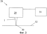
Фиг.4 схематически показывает третье контактное устройство с направляющими средствами в виде плоской пластины в соответствии с альтернативным вариантом осуществления настоящего изобретения;4 schematically shows a third contact device with guide means in the form of a flat plate in accordance with an alternative embodiment of the present invention;
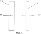
Фиг.5 показывает схематически край контактного узла в соответствии с альтернативным вариантом осуществления настоящего изобретения;Figure 5 shows schematically the edge of the contact node in accordance with an alternative embodiment of the present invention;
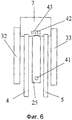
Фиг.6 показывает схематически край контактного узла в соответствии с альтернативным вариантом осуществления настоящего изобретения;6 shows schematically the edge of the contact node in accordance with an alternative embodiment of the present invention;
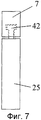
Фиг.7 показывает схематически часть контактного узла на Фиг.6 на виде, перпендикулярном виду на Фиг.6.Fig. 7 shows schematically a part of the contact assembly in Fig. 6 in a view perpendicular to the view in Fig. 6.
ОПИСАНИЕ ПРЕДПОЧТИТЕЛЬНЫХ ВАРИАНТОВ ОСУЩЕСТВЛЕНИЯ НАСТОЯЩЕГО ИЗОБРЕТЕНИЯDESCRIPTION OF THE PREFERRED EMBODIMENTS OF THE PRESENT INVENTION
В следующем далее описании предпочтительных вариантов осуществления настоящего изобретения, сходные детали на разных фигурах будут обозначены одинаковыми номерами позиций.In the following description of preferred embodiments of the present invention, like parts in different figures will be denoted by the same reference numerals.
Фиг.1 показывает контактный узел 1 в соответствии с одним из вариантов осуществления настоящего изобретения, тогда как Фиг.2 представляет собой изображение контактного узла на Фиг.1 в разобранном виде. Как показывается на Фиг.1, первая направляющая трубка 2 и вторая направляющая трубка 3 соединяются с контактным устройством 1 и располагаются для подвода первой сварочной проволоки 4 и второй сварочной проволоки 5 к контактному устройству 1.Figure 1 shows the
Контактный узел 1 содержит продольную ось 6, корпус 7 с первым краем 8 и вторым краем 9, через этот корпус 7 проходят сварочные проволоки 4, 5, располагаясь так, чтобы они выходили параллельно продольной оси от первого края 8 корпуса 7 до второго края 9 корпуса 7. Контактный узел 1 содержит также первое контактное устройство 32, которое содержит первую лапку 10 и первый контактный башмак 11. Первая лапка 10 имеет продолговатую форму и располагается неподвижно в корпусе 7 на первой стороне 12 корпуса 7, и простирается от первого края 24, который располагается между первым краем 8 корпуса 7 и вторым краем 9 корпуса, по существу параллельно продольной оси до второго края 13, который располагается на некотором расстоянии от корпуса 7. Первый контактный башмак 11 располагается на той стороне первой лапки, которая направлена вдаль от первой стороны 12 корпуса 7, чтобы он находился в контакте с первой сварочной проволокой 4, и простирается по существу вдаль от корпуса 7 к краю 13 первого контактного устройства. Первая лапка 10 прикрепляется к корпусу 7 посредством болтов лапки 19, и первый контактный башмак 11 прикрепляется к первой лапке 10 посредством первого набора болтов контактного башмака 20.The
Контактный узел 1, кроме того, содержит второе контактное устройство 33, которое содержит вторую лапку 14 и второй контактный башмак 15. Вторая лапка 14 имеет продолговатую форму и навешивается с подпружиниванием на корпус 7 на второй стороне 16 корпуса 7 и простирается от первого края 17, который располагается между первым краем 8 корпуса 7 и вторым краем 9 корпуса 7, по существу параллельно продольной оси до второго края 18, который располагается на некотором расстоянии от корпуса 7. Второй контактный башмак 15 располагается на той стороне второй лапки, которая направлена к первой лапке, для того, чтобы он находился в контакте со второй сварочной проволокой 5, и простирается по существу от корпуса 7 ко второму краю 18 второго контактного устройства. Второй контактный башмак 15 прикрепляется ко второй лапке 14 посредством второго набора болтов 29 контактного башмака. На второй стороне 16 корпуса 7, на некотором расстоянии от второго края 9 корпуса, располагается прямоугольный выступ 31, на который опирается первый край 17 второй лапки 14. Вторая лапка 14 содержит сквозные отверстия, через которые проходят подпружиненные болты 21 с головками болтов 22 и завинчиваются в корпусе 7. Между каждой головкой болта 22 и второй лапкой 14 располагаются подпружинивающие средства 23 в виде тарельчатых пружин, которые прикладывают силу ко второй лапке 14 и второму контактному башмаку 15 по направлению к первой лапке 10 и первому контактному башмаку 11.The
Как первая лапка 10, так и вторая лапка 14 имеют поперечное сечение, площадь которого уменьшается от корпуса 7 по направлению ко вторым краям 13, 18 лапок 10, 14. Из-за уменьшения площади поперечного сечения лапки 10, 14 будут иметь небольшое поперечное сечение на их вторых краях 13, 18 без прочностных рисков на лапках 10, 14. Поверхности контакта между каждой из лапок 10, 14 и соответствующими контактными башмаками 11, 15 являются по существу плоскими.Both the first foot 10 and the second foot 14 have a cross section whose area decreases from the
Между первым контактным башмаком 11 и вторым контактным башмаком 15 располагается третье контактное устройство 25 в виде третьего контактного башмака. Направляющие средства в виде направляющих стержней 26 располагаются неподвижно в третьем контактном устройстве 25 и проходят насквозь, и выступают на обеих сторонах третьего контактного устройства 25. В первом контактном башмаке 11 и во втором контактном башмаке 15 располагаются соответствующие отверстия 27, в которых располагаются направляющие стержни 26. Передача тока к третьему контактному устройству 25 может осуществляться либо напрямую от корпуса 7 к третьему контактному устройству 25, через первый контактный башмак 11, через второй контактный башмак 15, и/или через направляющие стержни 26.Between the first contact shoe 11 and the second contact shoe 15, there is a
На первой стороне 12 корпуса 7 располагается первая изолирующая накладка 30 для предотвращения нежелательных разрядов через первую сторону 12 контактного узла 1. Соответствующим образом располагается и вторая изолирующая накладка 34 на второй стороне 16 корпуса 7 для предотвращения нежелательных разрядов через вторую сторону 16 контактного узла 1. Первый зажим 35 и второй зажим 36 располагаются на первом краю 8 корпуса, для того чтобы обеспечить средства для закрепления контактного узла 1 в сварочном аппарате 28 (Фиг.3).On the first side 12 of the
Во время работы первая сварочная проволока 4 и вторая сварочная проволока 5 будут подаваться через первую направляющую трубку 2 и вторую направляющую трубку 3 к контактным башмакам 11, 15, так чтобы первая сварочная проволока 4 подавалась вперед между первым контактным башмаком 11 и третьим контактным башмаком 25, и так чтобы вторая сварочная проволока 5 подавалась вперед между вторым контактным башмаком 15 и третьим контактным башмаком 25. Второй контактный башмак 15 будет давить на вторую сварочную проволоку 5, которая в свою очередь давит на третий контактный башмак 25, который в свою очередь давит на первую сварочную проволоку 4. Контактные башмаки 11, 15, 25 будут таким образом давить на сварочные проволоки 4,5, независимо от диаметра и кривизны проволок.During operation, the
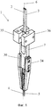
На Фиг.3 показывается схематически сварочный аппарат 28 для порошковой сварки, данный сварочный аппарат 28 содержит контактный узел 1 в соответствии с настоящим изобретением. Сварочный аппарат содержит подающее устройство, которое располагается для подачи сварочной проволоки 30 к контактному устройству 1 и которое подключается к источнику напряжения для приложения напряжения между контактным устройством 1 и поверхностью сварки 32.Figure 3 shows schematically a
Фиг.4a схематически показывает третье контактное устройство 25 с направляющими средствами в виде плоской пластины 37 в соответствии с альтернативным вариантом осуществления настоящего изобретения. На Фиг.4b третье контактное устройство 25 показывается с плоской пластиной 37 на виде, который является перпендикулярным к первому виду.4a schematically shows a
Фиг.5a схематически показывает край контактного узла 1 в соответствии с альтернативным вариантом осуществления настоящего изобретения. Фиг.5b показывает то же контактное устройство на виде снизу, перпендикулярном виду на Фиг.5a. Первое контактное устройство 32 имеет, если смотреть на вид на Фиг.5a, форму буквы L. На виде на Фиг.5b показан мостик 38, который разделяет отверстие 39, в этом отверстии 39 располагается для прохождения первая сварочная проволока 4, а также канавка 40, в этой канавке 40 располагается для прохождения вторая сварочная проволока 5. Третье контактное устройство 25 опирается на мостик 38, который препятствует выпадению третьего контактного устройства 25. Таким образом, третье контактное устройство 25 не должно обязательно снабжаться каким-либо направляющим средством. Второе контактное устройство 33 располагается для прохождения в канавке 40. Либо первое контактное устройство 32, либо второе контактное устройство 33 может располагаться с подпружиниванием. Назначение контактного узла на Фиг.5 сходно с тем, что было описано выше.Fig. 5a schematically shows the edge of the
Фиг.6 схематически показывает край контактного узла в соответствии с альтернативным вариантом осуществления настоящего изобретения. Будут описываться только различия между контактным узлом на Фиг.6 и контактным узлом на Фиг.1 и Фиг.2. Третье контактное устройство 25 содержит направляющие средства в виде направляющего стержня 42, который располагается для прохождения в изогнутой канавке 43 в корпусе 7 с возможностью для вращения вокруг оси вращения 41.6 schematically shows the edge of the contact node in accordance with an alternative embodiment of the present invention. Only differences between the contact node in FIG. 6 and the contact node in FIG. 1 and FIG. 2 will be described. The
Фиг.7 схематически показывает узел контактного узла на Фиг.6 на виде, перпендикулярном виду на Фиг.6, на этом виде показано, что направляющий стержень 42 формируется в форме буквы Т.Fig. 7 schematically shows the contact node assembly in Fig. 6 in a view perpendicular to the view in Fig. 6, in this view it is shown that the
Описанные варианты осуществления могут изменяться разными путями без отклонения от духа и рамок настоящего изобретения, которые ограничиваются только прилагаемой формулой изобретения.The described embodiments may vary in various ways without departing from the spirit and scope of the present invention, which is limited only by the attached claims.
Разумеется, можно расположить третий контактный башмак с возможностью перемещения в направлении, ином, чем описано выше. Например, третий контактный башмак может иметь возможность для вращения вокруг точки крепления на корпусе 1.Of course, it is possible to arrange the third contact shoe with the ability to move in a direction other than that described above. For example, the third contact shoe may be able to rotate around the attachment point on the
Можно позволить как первому контактному башмаку 11, так и второму контактному башмаку 15 иметь подпружинивание, так чтобы они оба прижимались к общему третьему контактному башмаку 25.It is possible to allow both the first contact shoe 11 and the second contact shoe 15 to be spring-loaded so that they both are pressed against a common
Контактный узел в соответствии с настоящим изобретением может использоваться также вместе с формами сварки, иными чем порошковая сварка (PW).The contact assembly in accordance with the present invention can also be used in conjunction with forms of welding other than powder welding (PW).
Описанная выше канавка в форме буквы Т для третьего контактного башмака может альтернативно иметь другую форму, которая не дает направляющему стержню покидать канавку. С учетом описания, которое приведено выше, для специалистов в данной области было бы просто разработать направляющий стержень по-другому.The T-shaped groove described above for the third contact shoe may alternatively have a different shape that prevents the guide pin from leaving the groove. Given the description given above, it would be simple for those skilled in the art to develop a guide rod differently.
Claims (23)
Applications Claiming Priority (2)
| Application Number | Priority Date | Filing Date | Title |
|---|---|---|---|
| SE0700548-1 | 2007-03-06 | ||
| SE0700548A SE530969C2 (en) | 2007-03-06 | 2007-03-06 | Connectors and welding apparatus |
Publications (2)
| Publication Number | Publication Date |
|---|---|
| RU2009136686A RU2009136686A (en) | 2011-04-20 |
| RU2466836C2 true RU2466836C2 (en) | 2012-11-20 |
Family
ID=39738508
Family Applications (1)
| Application Number | Title | Priority Date | Filing Date |
|---|---|---|---|
| RU2009136686/02A RU2466836C2 (en) | 2007-03-06 | 2008-03-04 | Welding set contact assembly |
Country Status (7)
| Country | Link |
|---|---|
| US (1) | US8247737B2 (en) |
| EP (1) | EP2131990B1 (en) |
| JP (1) | JP5270584B2 (en) |
| CN (1) | CN101657287B (en) |
| RU (1) | RU2466836C2 (en) |
| SE (1) | SE530969C2 (en) |
| WO (1) | WO2008108728A1 (en) |
Cited By (1)
| Publication number | Priority date | Publication date | Assignee | Title |
|---|---|---|---|---|
| RU2596570C2 (en) * | 2013-07-09 | 2016-09-10 | Общество с ограниченной ответственностью "АС и ПП" | Liquid-vapor plasmatron |
Families Citing this family (7)
| Publication number | Priority date | Publication date | Assignee | Title |
|---|---|---|---|---|
| RU2475345C2 (en) * | 2011-04-25 | 2013-02-20 | Алексей Владимирович Зинченко | Device to apply reverse potential to welded structure |
| US10486256B2 (en) | 2012-12-28 | 2019-11-26 | Esab Ab | Arc welding method and arc welding arrangement with first and second electrodes |
| CN104028889B (en) * | 2014-06-17 | 2017-01-04 | 上海中远川崎重工钢结构有限公司 | A kind of electroslag welding welding guides fixture and manufacture method thereof |
| US10857617B2 (en) * | 2017-06-22 | 2020-12-08 | Esab Ab | Contact nozzle with split tip |
| US10857615B2 (en) | 2017-06-22 | 2020-12-08 | Esab Ab | Self-adjusting twin contact jaws |
| NL2020115B1 (en) * | 2017-12-18 | 2019-06-25 | Sif Group | Welding torch and welding device |
| CN108436236A (en) * | 2018-06-01 | 2018-08-24 | 西安增材制造国家研究院有限公司 | A kind of ignition tip |
Citations (8)
| Publication number | Priority date | Publication date | Assignee | Title |
|---|---|---|---|---|
| DE2146406A1 (en) * | 1971-09-16 | 1973-03-22 | Messer Griesheim Gmbh | PROCESS FOR SUB-FLOWDER JOINT WELDING OF LARGE CROSS SECTIONS ON WORKPIECES MADE OF STEEL |
| SU389899A1 (en) * | 1971-07-16 | 1973-07-11 | Институт электросварки Е. О. Патона | DEVICE FOR THE CONTACT SUPPLY OF WELDING CURRENT TO WELDING WIRE |
| SU502722A1 (en) * | 1973-04-09 | 1976-02-15 | Device for contact current supply to welding wire | |
| GB1451495A (en) * | 1972-12-21 | 1976-10-06 | Fives Cail Babcock | Welding unit |
| SU649522A1 (en) * | 1976-10-04 | 1979-02-28 | Предприятие П/Я В-2946 | Apparatus for contact supply of current to wire electrode |
| EP0224669A2 (en) * | 1985-11-23 | 1987-06-10 | Man Gutehoffnungshütte Gmbh | Device for submerged welding with several thread electrodes ordered side by side or in front and behind |
| RU2256539C2 (en) * | 2003-07-11 | 2005-07-20 | Кручинин Юрий Николаевич | Attachment for surfacing inner surface of small-diameter openings |
| UA16364U (en) * | 2005-12-19 | 2006-08-15 | Open Joint Stock Company Centr | Mouthpiece of welding head |
Family Cites Families (8)
| Publication number | Priority date | Publication date | Assignee | Title |
|---|---|---|---|---|
| AT313026B (en) * | 1969-12-24 | 1974-01-25 | Boehler & Co Ag Geb | Arc fusion welding process |
| GB1397236A (en) | 1974-02-13 | 1975-06-11 | British Oxygen Co Ltd | Arc welding |
| DE2949318C2 (en) | 1979-12-05 | 1982-10-28 | Mannesmann AG, 4000 Düsseldorf | Arc welding torch |
| CN2133398Y (en) * | 1992-06-24 | 1993-05-19 | 南京化学工业(集团)公司化工机械厂换热器分厂 | Contact nozzle of automatic submerged arc welding machine |
| JP2002001542A (en) * | 2000-06-15 | 2002-01-08 | Babcock Hitachi Kk | Torch for hot wire gma welding |
| US6559416B1 (en) * | 2000-08-25 | 2003-05-06 | Illinois Tool Works | Alternate current path for mig gun |
| CN2495406Y (en) * | 2001-07-01 | 2002-06-19 | 应展 | Clamping type electrode holder |
| US7262386B2 (en) * | 2004-05-12 | 2007-08-28 | Lincoln Global, Inc. | Method of pulse welding and contact tip therefor |
-
2007
- 2007-03-06 SE SE0700548A patent/SE530969C2/en unknown
-
2008
- 2008-03-04 CN CN2008800071796A patent/CN101657287B/en active Active
- 2008-03-04 JP JP2009552639A patent/JP5270584B2/en active Active
- 2008-03-04 EP EP08724187A patent/EP2131990B1/en active Active
- 2008-03-04 RU RU2009136686/02A patent/RU2466836C2/en not_active IP Right Cessation
- 2008-03-04 US US12/530,160 patent/US8247737B2/en active Active
- 2008-03-04 WO PCT/SE2008/050240 patent/WO2008108728A1/en active Application Filing
Patent Citations (8)
| Publication number | Priority date | Publication date | Assignee | Title |
|---|---|---|---|---|
| SU389899A1 (en) * | 1971-07-16 | 1973-07-11 | Институт электросварки Е. О. Патона | DEVICE FOR THE CONTACT SUPPLY OF WELDING CURRENT TO WELDING WIRE |
| DE2146406A1 (en) * | 1971-09-16 | 1973-03-22 | Messer Griesheim Gmbh | PROCESS FOR SUB-FLOWDER JOINT WELDING OF LARGE CROSS SECTIONS ON WORKPIECES MADE OF STEEL |
| GB1451495A (en) * | 1972-12-21 | 1976-10-06 | Fives Cail Babcock | Welding unit |
| SU502722A1 (en) * | 1973-04-09 | 1976-02-15 | Device for contact current supply to welding wire | |
| SU649522A1 (en) * | 1976-10-04 | 1979-02-28 | Предприятие П/Я В-2946 | Apparatus for contact supply of current to wire electrode |
| EP0224669A2 (en) * | 1985-11-23 | 1987-06-10 | Man Gutehoffnungshütte Gmbh | Device for submerged welding with several thread electrodes ordered side by side or in front and behind |
| RU2256539C2 (en) * | 2003-07-11 | 2005-07-20 | Кручинин Юрий Николаевич | Attachment for surfacing inner surface of small-diameter openings |
| UA16364U (en) * | 2005-12-19 | 2006-08-15 | Open Joint Stock Company Centr | Mouthpiece of welding head |
Cited By (1)
| Publication number | Priority date | Publication date | Assignee | Title |
|---|---|---|---|---|
| RU2596570C2 (en) * | 2013-07-09 | 2016-09-10 | Общество с ограниченной ответственностью "АС и ПП" | Liquid-vapor plasmatron |
Also Published As
| Publication number | Publication date |
|---|---|
| WO2008108728A8 (en) | 2011-04-21 |
| US8247737B2 (en) | 2012-08-21 |
| US20100140242A1 (en) | 2010-06-10 |
| JP5270584B2 (en) | 2013-08-21 |
| WO2008108728A1 (en) | 2008-09-12 |
| CN101657287A (en) | 2010-02-24 |
| RU2009136686A (en) | 2011-04-20 |
| CN101657287B (en) | 2012-05-30 |
| SE0700548L (en) | 2008-09-07 |
| JP2010520062A (en) | 2010-06-10 |
| EP2131990B1 (en) | 2012-10-17 |
| EP2131990A1 (en) | 2009-12-16 |
| SE530969C2 (en) | 2008-11-04 |
| EP2131990A4 (en) | 2011-06-22 |
Similar Documents
| Publication | Publication Date | Title |
|---|---|---|
| RU2466836C2 (en) | Welding set contact assembly | |
| US8231416B2 (en) | Spring contact assembly | |
| CN103590989B (en) | Drive unit with and manufacture method | |
| US20170097376A1 (en) | Spring probe having outer sleeve and probe device having the same | |
| US20130146644A1 (en) | Method and arrangement for welding electrical conductors | |
| US20130213754A1 (en) | Segmented collector shoe assembly | |
| JP2016183550A (en) | Height adaptation for railroad rail fastener assembly | |
| CN210665826U (en) | Contact device | |
| KR102191590B1 (en) | Electrode Apparatus For Plating | |
| CN101386108B (en) | Electrode of seam welder | |
| CN104640665A (en) | Spring assembly, machine, and weld head | |
| KR102030774B1 (en) | Electric resistance spot welding machine with double composite electrodes and induction heating | |
| JP2017533136A (en) | Vehicle connection system for guiding at least one supply cable and clamping member for such a vehicle connection system | |
| BRPI1102462B1 (en) | compression module for conductive bars impregnated with large electrical machines and compression apparatus equipped with the same | |
| CN104458440B (en) | Mechanism for detecting breaking strength of bar | |
| RU2381882C2 (en) | Hanging machinery for upset welding of rails | |
| CN203720062U (en) | Hot compression tester and pressing head assembly thereof | |
| KR101247105B1 (en) | A tip unit of spot welding gun | |
| CN204286949U (en) | Bar rupture strength testing agency | |
| JP5936579B2 (en) | Current application device | |
| JP6428238B2 (en) | Trolley wire support device | |
| CN111331210B (en) | Wire clamping device and manipulator | |
| DE102006058586A1 (en) | Optical head | |
| KR102593612B1 (en) | Probe device | |
| KR20120087595A (en) | Head of electro polishing |
Legal Events
| Date | Code | Title | Description |
|---|---|---|---|
| MM4A | The patent is invalid due to non-payment of fees |
Effective date: 20170305 |