RU2463413C2 - Composite product for designed slabs - Google Patents
Composite product for designed slabs Download PDFInfo
- Publication number
- RU2463413C2 RU2463413C2 RU2008124937/03A RU2008124937A RU2463413C2 RU 2463413 C2 RU2463413 C2 RU 2463413C2 RU 2008124937/03 A RU2008124937/03 A RU 2008124937/03A RU 2008124937 A RU2008124937 A RU 2008124937A RU 2463413 C2 RU2463413 C2 RU 2463413C2
- Authority
- RU
- Russia
- Prior art keywords
- composite product
- metal
- plastic
- product according
- frame
- Prior art date
Links
Images


Classifications
-
- E—FIXED CONSTRUCTIONS
- E04—BUILDING
- E04B—GENERAL BUILDING CONSTRUCTIONS; WALLS, e.g. PARTITIONS; ROOFS; FLOORS; CEILINGS; INSULATION OR OTHER PROTECTION OF BUILDINGS
- E04B5/00—Floors; Floor construction with regard to insulation; Connections specially adapted therefor
- E04B5/16—Load-carrying floor structures wholly or partly cast or similarly formed in situ
- E04B5/17—Floor structures partly formed in situ
- E04B5/18—Floor structures partly formed in situ with stiffening ribs or other beam-like formations wholly cast between filling members
- E04B5/19—Floor structures partly formed in situ with stiffening ribs or other beam-like formations wholly cast between filling members the filling members acting as self-supporting permanent forms
-
- E—FIXED CONSTRUCTIONS
- E04—BUILDING
- E04B—GENERAL BUILDING CONSTRUCTIONS; WALLS, e.g. PARTITIONS; ROOFS; FLOORS; CEILINGS; INSULATION OR OTHER PROTECTION OF BUILDINGS
- E04B5/00—Floors; Floor construction with regard to insulation; Connections specially adapted therefor
- E04B5/16—Load-carrying floor structures wholly or partly cast or similarly formed in situ
- E04B5/32—Floor structures wholly cast in situ with or without form units or reinforcements
- E04B5/36—Floor structures wholly cast in situ with or without form units or reinforcements with form units as part of the floor
-
- E—FIXED CONSTRUCTIONS
- E04—BUILDING
- E04C—STRUCTURAL ELEMENTS; BUILDING MATERIALS
- E04C5/00—Reinforcing elements, e.g. for concrete; Auxiliary elements therefor
- E04C5/01—Reinforcing elements of metal, e.g. with non-structural coatings
- E04C5/06—Reinforcing elements of metal, e.g. with non-structural coatings of high bending resistance, i.e. of essentially three-dimensional extent, e.g. lattice girders
- E04C5/065—Light-weight girders, e.g. with precast parts
Abstract
Description
Настоящее изобретение относится в общем к изготовленным изделиям для конструируемых перекрытий зданий, и в частности панелей из расширяющегося при застывании пластмассового материала, имеющего каналы, подходящие, чтобы вмещать разнесенные на расстояние опорные арматурные стальные стержни для образования параллельных несущих железобетонных ребер и возможных поперечных ребер жесткости, после укрепления бетонным наполнителем, механизированным по всем настеленным панелям и армированным конструкциям.The present invention relates generally to manufactured products for constructed ceilings of buildings, and in particular, panels made of expandable when solidified plastic material having channels suitable to accommodate spaced support reinforcing steel bars for forming parallel load-bearing reinforced concrete ribs and possible transverse stiffeners, after reinforcement with a concrete filler mechanized on all wall panels and reinforced structures.
Технология системы образования встроенного укрепляющего теплоизоляционного бетона для балочных бетонированных перекрытий, использующих желобчатые панели из расширяющейся при застывании пластмассы, связанной с арматурными стальными стержнями несущих ребер жесткости, выполненных после укрепления каналов уложенным бетонным наполнителем, определенных в панелях из расширяющейся при застывании пластмассы для приспособления каркасов из арматурных стержней, известны и обычно используются в строительной промышленности зданий из железобетона.The technology of the system for the formation of built-in reinforcing heat-insulating concrete for concrete girders using gutter panels made of expanding plastic when bonded, connected to reinforcing steel rods of bearing stiffeners made after reinforcing the channels with laid concrete filler, defined in panels made of expanding plastic when setting, to adapt the frameworks from reinforcing bars are known and commonly used in the construction industry of buildings made of iron concrete.
В публикациях WO 2005/108700-A1 и WO 2005/121467 A2 раскрыты важные примеры такой технологии для конструируемых перекрытий в альтернативе к традиционной технологии, использующей изготовленные заранее несущие железобетонные балки и соединяющие пустотелые кирпичи перекрытий, расположенные между ними.Publications WO 2005/108700-A1 and WO 2005/121467 A2 disclose important examples of such a technology for constructed floors in alternative to the traditional technology using prefabricated reinforced concrete beams and connecting hollow floor bricks located between them.
Высокая степень автоматизации, которая является реальной в изготовлении панелей из расширяющейся при застывании пластмассы, металлические элементы непосредственно каркасов зданий из отдельно стоящих и/или арматурных стальных стержней для бетонных ребер жесткости, подлежащие образованию, панелей из расширяющейся при застывании пластмассы по сравнению с обычными материалами, используемыми для конструируемых перекрытий, таких как изготовленные заранее железобетонные балки и соединяющие пустотелые кирпичи перекрытий, значительно уменьшают затраты на транспортировку и настилание панелей и каркасов зданий из арматурных стальных стержней, на которые в конечном счете наливают бетон. Эта технология упрощает конструкцию перекрытий при заметно уменьшенной стоимости и увеличивает акустические и термоизоляционные характеристики.A high degree of automation, which is real in the manufacture of panels made of expanding plastic during hardening, metal elements of building frames directly from free-standing and / or reinforcing steel rods for concrete stiffeners to be formed, panels made of plastic expanding when solidified, compared to conventional materials, used for designed floors, such as prefabricated reinforced concrete beams and connecting hollow bricks of floors, significantly nshayut transportation costs and coanda panels and building frameworks of steel reinforcing bars, which eventually poured concrete. This technology simplifies the design of floors with a markedly reduced cost and increases acoustic and thermal insulation characteristics.
Затраты на рабочую силу в укладывании панелей из расширяющейся при застывании пластмассы и армированных металлический конструкций (каркасов зданий) в каналах, выполненных в панелях из расширяющейся при застывании пластмассы и возможных других металлических элементах для обеспечения соответствующих собственно постоянных свойств настилаемых панелей и укрепляющих конструкций, на которые будут наливать и равномерно распределять бетон, остается еще важным фактором стоимости. Кроме того, сборка и укладывание индивидуальных компонентов на строительной площадке могут приводить к неточностям сборки, которые, в худшем случае, могут определять неустойчивость арматурных металлических конструкций внутри каналов, определенных в корпусе панелей из расширяющейся при застывании пластмассы, во время распределения уложенного бетона.Labor costs for laying panels made of expandable plastic when setting and reinforced metal structures (building frames) in channels made in panels made of expanding plastic when set and other possible metal elements to ensure the corresponding constant properties of the laid panels and reinforcing structures on which will pour and evenly distribute concrete, remains an important cost factor. In addition, the assembly and laying of individual components at a construction site can lead to inaccuracies in the assembly, which, in the worst case, can determine the instability of reinforcing metal structures inside channels defined in the case of panels made of expanding plastic during solidification during distribution of the laid concrete.
Особенно перекрытия, изготовленные по этой технологии, имеют уменьшенную способность замедлять проникновение огня в готовую конструкцию перекрытия, поскольку чрезмерное сжатие корпусов из расширяющейся при застывании пластмассы, вызванное длительным подверганием воздействию сильного тепла, может привести к отслаиванию намета штукатурки или падению штукатурных плит или другого облицовочного слоя обратной стороны потолка.Especially the floors made by this technology have a reduced ability to slow down the penetration of fire into the finished floor structure, since excessive compression of the shells from expanding plastic during hardening, caused by prolonged exposure to strong heat, can lead to peeling of the plaster coating or to the fall of plasterboards or other coating layer back side of the ceiling.
Важно, что в случае пожара, несмотря на то, что расширяющаяся при застывании пластмасса может давать усадку до образования неформальных масс уменьшенного объема штукатурки или облицовки обратной стороны потолка, например, один или больше слоев штукатурки или облицовки штукатурных плит остаются на месте для предотвращения проникновения огня.It is important that in case of fire, despite the fact that the plastic expanding during solidification can shrink before the formation of informal masses of a reduced volume of plaster or lining the back of the ceiling, for example, one or more layers of plaster or lining of plasterboards remain in place to prevent the ingress of fire .
Составное изделие изготовления для конструирования бетонированных перекрытий теперь создают так, чтобы оно все целиком было сборкой на предприятии-изготовителе при максимальном уменьшении стоимости, сохраняя автоматизированные средства обслуживания и исключая надежный контроль за качеством.A composite manufacturing product for the construction of concrete floors is now created so that it is completely assembled at the manufacturer with the maximum cost reduction, while maintaining automated facilities and eliminating reliable quality control.
Составные панели, собранные на предприятии-изготовителе по этому изобретению, требуют минимальных трудовых и относительных затрат, необходимых для укладывания полностью предварительно смонтированных составных изделий на строительной площадке и почти полного устранения рисков ошибок сборки во время подготовки помоста настила, на который будет в конце концов распределен укладываемый бетон.Composite panels assembled at the manufacturer's site according to this invention require minimal labor and relative costs required for laying completely pre-assembled composite products at a construction site and almost completely eliminate the risks of assembly errors during the preparation of the flooring platform, which will eventually be distributed stacked concrete.
Кроме того, новая конструкция заранее смонтированных составных панелей увеличивает стабильность покрытий и облицовок, которые можно прикладывать к поверхности обратной стороны законченного перекрытия в случае пожара, несмотря на уменьшение участков из расширяющейся при застывании пластмассы.In addition, the new design of pre-assembled composite panels increases the stability of coatings and claddings that can be applied to the surface of the back side of a finished floor in case of fire, despite the reduction of areas of expanding plastic when hardening.
Согласно предпочтительному варианту осуществления, вся поверхность обратной стороны составного изделия имеет металлический листовой экран, прочность которого по существу сохраняется даже в случае пожара. Металлический экран составных панелей обеспечивает металлическую облицовку, по существу свободную от неоднородности по всей поверхности обратной стороны перекрытия.According to a preferred embodiment, the entire surface of the back side of the composite product has a metal sheet screen, the strength of which is essentially maintained even in the event of a fire. The metal screen of the composite panels provides a metal cladding substantially free of inhomogeneity over the entire surface of the reverse side of the floor.
В ситуациях, в которых не требуются конкретные эстетические качества, внешняя облицовка металлического листа поверхности потолка законченного перекрытия может даже оставаться в поле зрения (например, в случае потолков подземных складских площадей, гаражей и т.п.).In situations in which specific aesthetic qualities are not required, the external cladding of the metal sheet of the ceiling surface of the finished floor may even remain in sight (for example, in the case of ceilings of underground storage areas, garages, etc.).
В качестве альтернативы, облицовочный металлический лист составного изделия, изготовленный по настоящему изобретению, обеспечивает анкерный элемент для общих потолочных покрытий, таких как штукатурка, штукатурная плита и подобных.Alternatively, the cladding metal sheet of a composite product made according to the present invention provides an anchor element for general ceiling coatings, such as plaster, plasterboard and the like.
В основном, составная панель по настоящему изобретению содержит корпус из расширяющейся при застывании пластмассы, имеющий по меньшей мере два параллельных канала, открытых на верхней поверхности панели, которые продолжаются по всей длине изделия, приспособленные для заполнения бетоном, разливаемым по панели. Каркас из стального арматурного стержня устанавливают в каждый канал. Его можно составлять по меньшей мере из двух параллельных стальных стержней, соединенных в соответствии с по меньшей мере рядом поперечных стержней, расположенных равномерно вдоль отрезка армированного каркаса. По меньшей мере такие же или предпочтительно все поперечные стержни продолжаются за пределы самого нижнего арматурного стального стержня каркаса для составления множества костылей достаточной длины, для прохождения через основание из расширяющейся при застывании пластмассы вмещающего канала, чтобы выдерживать в устойчивом вертикальном положении внутри канала армированный каркас, и выступают от поверхности обратной стороны корпуса из расширяющейся при застывании пластмассы.Basically, the composite panel of the present invention comprises a housing made of expandable upon hardening plastic, having at least two parallel channels open on the upper surface of the panel, which extend along the entire length of the product, adapted to be filled with concrete poured on the panel. The frame of the steel reinforcing bar is installed in each channel. It can be composed of at least two parallel steel rods connected in accordance with at least a number of transverse rods arranged uniformly along a section of the reinforced frame. At least the same or preferably all of the transverse rods extend beyond the bottommost reinforcing steel core of the frame to form a plurality of crutches of sufficient length to pass through the base of the expanding duct extending when hardening plastic to maintain the reinforced framework in a stable upright position inside the duct, and protrude from the surface of the reverse side of the housing from expanding during solidification of plastic.
Один или более прокатанных или штампованных экранов из листового металла по меньшей мере с одним рядом выровненных отверстий, разделенных от друг друга промежутками, идентичными промежуткам упомянутого множества выступающих концов костылей, прикладывают к поверхности обратной стороны корпуса из расширяющейся при застывании пластмассы, подвешивая от выступающих концов костыля посредством крепежных гаек или наконечников, устойчиво зацепленными с концами армированного каркаса металлического корпуса костыля, которые закрывают отверстие прохода костылей.One or more rolled or stamped sheet metal shields with at least one row of aligned holes separated by gaps identical to the gaps of the plurality of protruding ends of the crutches are applied to the surface of the back of the casing made of plastic expanding when solidified, hanging from the protruding ends of the crutch by means of fastening nuts or tips, stably engaged with the ends of the reinforced frame of the metal body of the crutch, which cover the opening the passage of crutches.
Крепежные гайки или наконечники можно изготавливать из достаточно ковкого металлического материала, приспособленного для автоматического нарезания резьбы винтообразной формы, образованной в торцевом положении металлических костылей, или пластмассового материала, имеющего существенное сопротивление огню, такого, как например, политетрафторэтилен или подобный.The fastening nuts or tips can be made of a sufficiently malleable metal material adapted to automatically thread a screw-shaped thread formed in the end position of metal crutches, or a plastic material having substantial fire resistance, such as, for example, polytetrafluoroethylene or the like.
Предпочтительно, перед монтажом каркаса из арматурного стержня, в канал корпуса из расширяющейся при застывании пластмассы соответствующие разнесенные на расстояние противодействующие наконечники из такого же материала крепежных наконечников или даже из другого материала проскальзывают по металлическим костылям, чтобы увеличивать стабилизацию каркаса здания из арматурного стержня и поддерживать его в точно вертикальном положении в приемном канале, отделенном от нижней поверхности канала в корпусе из расширяющейся при застывании пластмассы, в котором он размещен.Preferably, before mounting the frame from the reinforcing bar, into the body channel of the expanding plastic during hardening, the corresponding opposed spacing tips of the same material of the mounting tips or even of another material slip on metal crutches in order to increase the stabilization of the building frame from the reinforcing bar in exactly vertical position in the receiving channel, separated from the lower surface of the channel in the housing from expanding when solidified lastmassy in which it is placed.
Изобретение определено в прилагаемой формуле изобретения.The invention is defined in the attached claims.
Сущность изобретения поясняется на чертежах, где изображено следующее.The invention is illustrated in the drawings, which depict the following.
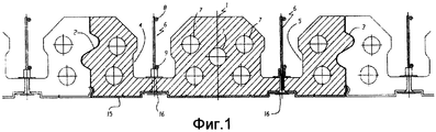
Фиг.1 - вид в поперечном разрезе составного изделия изготовления по настоящему изобретению.Figure 1 is a view in cross section of a composite product manufacturing according to the present invention.
Фиг.2 - продольный вид примерного каркаса из арматурного стержня, подлежащего укладыванию внутри приемного канала корпуса из расширяющейся при застывании пластмассы.Figure 2 is a longitudinal view of an exemplary frame of a reinforcing bar to be laid inside the receiving channel of the housing of expanding plastic when solidified.
Фиг.3 - сборка трех основных компонентов составной конструкции изделия изготовления.Figure 3 - Assembly of the three main components of the composite structure of the product.
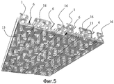
Фиг.4 и 5 - трехмерные фотографические изображения, показывающие конструкцию составного изделия по настоящему изобретению согласно первому примерному варианту осуществления.4 and 5 are three-dimensional photographic images showing the construction of a composite product of the present invention according to the first exemplary embodiment.
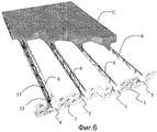
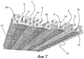
Фиг.6 и 7 - трехмерные фотографические изображения конструкции составного изделия по настоящему изобретению согласно другому примерному варианту осуществления.6 and 7 are three-dimensional photographic images of the construction of a composite product of the present invention according to another exemplary embodiment.
Следующее подробное описание некоторых вариантов осуществления, показанных на чертежах, не исключает каким-либо образом другие возможные формы реализации составного изделия изготовления по настоящему изобретению.The following detailed description of some of the embodiments shown in the drawings does not in any way exclude other possible forms of implementation of the composite product of manufacture of the present invention.
В примерных показанных вариантах осуществления корпус из расширяющейся при застывании пластмассы каждой составной панели имеет два параллельных канала, открытых на верхней стороне корпуса из расширяющейся при застывании пластмассы, продолжающиеся по всей длине, которая в конечном счете будет заполнена смесью уложенного бетона. Конечно, каждые корпуса из расширяющейся при застывании пластмассы могут иметь больше двух открытых каналов панелей для реализации более двух несущих арматурных железобетонных балок согласно вариантам конструкции, имеющим пропорционально большую ширину и даже различные приспособления продольных углублений для уменьшения массы расширяющегося при застывании пластмассового материала.In the exemplary embodiments shown, the casing of the expandable upon curing plastic of each composite panel has two parallel channels open on the upper side of the casing of the expanding upon hardening plastic, extending over the entire length that will eventually be filled with the concrete mix laid. Of course, each housing made of expandable during hardening plastic may have more than two open channel channels for the implementation of more than two load-bearing reinforced concrete beams according to design options having a proportionally large width and even various devices of longitudinal recesses to reduce the mass of expanding when hardening plastic material.
На фиг.1 и 2 показано составное изделие, по настоящему изобретению, состоящее из корпуса 1 из расширяющейся при застывании пластмассы в общем удлиненной параллелепипедальной формы с продольными профилями 2 и 3 задней поверхности, образованными способом, чтобы располагаться соединенными в шип и в паз друг с другом, согласно обычным способам, используемым в промышленности. Продольные углубления 7 для уменьшения массы расширяющейся при застывании пластмассы и обеспечения продольных проходов для труб или кабелей могут также присутствовать согласно обычным способам изготовления этих элементов.Figures 1 and 2 show a composite product according to the present invention, consisting of a
В показанном примере, корпус 1 из расширяющейся при застывании пластмассы определяет два параллельных открытых канала 4 и 5, внутри которых каркасы 6 из арматурных стержней для несущих балок, подлежащих образованию после усиления смесью уложенного бетона, предварительно устанавливают на предприятии-изготовителе.In the shown example, the
В показанном примере, армированные каркасы 6 включают в себя арматурный верхний стальной стержень 8, арматурный нижний стальной стержень 9, порядок стального поперечного стержня 10 и порядок распорных стальных ребер 11 жесткости.In the example shown, the reinforced
Предпочтительно, как показано, все поперечные стержни 10 продолжаются за пределы нижнего стержня 9 армированного каркаса 6 для того, чтобы составлять столько костылей 12, чтобы длина была достаточной для прохождения через основание расширяющейся при застывании пластмассы вмещающего канала армированного каркаса, до достижения близкого расположения к поверхности обратной стороны корпуса 1 из расширяющейся при застывании пластмассы или немного выступая из него.Preferably, as shown, all of the
Как показано на фиг.1 и 2, основание канала из расширяющейся при застывании пластмассы можно всегда выполнять с отверстиями с равными интервалами так, чтобы через них проходили костыли 12. В качестве альтернативы, сборку составного изделия можно выполнять, пронизывая расширяющуюся при застывании пластмассу стенки основания костылями 12 непосредственно, проталкивая армированный металлический каркас в положение в канал.As shown in figures 1 and 2, the base of the channel from expanding during solidification of the plastic can always be performed with holes at equal intervals so that
Предпочтительно, как показано на чертежах, перед прохождением костылей 12 через стенку основания канала, противодействующие наконечники 13 распорной детали, предпочтительно из пластмассового материала, каждый имеющий торцевой фланец 14 для того, чтобы опираться на нижнюю поверхность расширяющейся при застывании пластмассы канала, вмещающего армированный каркас, проскальзывают по костылям 12.Preferably, as shown in the drawings, before passing the
Затем на поверхность обратной стороны корпуса 1 из расширяющейся при застывании пластмассы накладывают прокатанный или штампованный экран из листового металла, который может иметь вверх загнутые боковые края, приспособленный для его оборачивания вокруг нижних углов корпуса из расширяющейся при застывании пластмассы все время вдоль его задней поверхности.Then, a rolled or stamped sheet metal screen is applied to the surface of the back side of the
Прокатанный или в качестве альтернативы штампованный прессовкой листовой металл 15 имеет в длину выровненные отверстия с таким же шагом (с равными промежутками) оси костылей 12 и его прокатанный или образованный прессовкой профиль соответствует профилю нижней поверхности корпуса из расширяющейся при застывании пластмассы.Laminated or alternatively pressed by pressed
Крепежные гайки или наконечники 16, имеющие концевой фланец и трубчатый ствол, устойчиво зацепляют с концами костылей 12, на которых их стягивают так, чтобы обеспечивать устойчивое соединение между армированным каркасом 6 и экраном 15 из листового металла, накладываемым на поверхность обратной стороны изготовленного изделия. Экран 15 из листового металла, таким образом присоединенный к корпусу из расширяющейся при застывании смолы, сравнивают с соединением увеличенной непосредственно постоянной способности, действуя в качестве придания жесткости и защиты арматуры, которые обеспечивают безопасную обработку, транспортировку и укладывание предварительно собранной на предприятии составной панели.Fixing nuts or
Стягивание и закрепление наконечников 16 эффективно стабилизирует установленный армированный каркас 6, так же, как укрепленный металлический листовой экран 15, соединенный с корпусом из расширяющейся при застывании пластмассы, создавая возможно обработку с легкостью полностью собранных составных панелей без рисков их повреждения для транспортировки их от предприятия до строительной площадки, которые будут легко и быстро уложены для конструирования платформ перекрытия, просто соединяя одну составную панель с другой по временным лесам.Pulling and securing the
Путь, которым три существенные компонента составного изделия по настоящему изобретению, а именно корпус 1 из расширяющейся при застывании пластмассы, каркас здания 6 из арматурного металла и укрепленный экран 11 из листового металла, собирают для образования составного изделия, подходящего для хранения, транспортировки и укладывания на строительной площадке, графически представлен на фиг.3.The way in which the three essential components of the composite product of the present invention, namely the
Предпочтительно, как в примере, показанном на чертеже, концы костылей 12 обеспечивают винтообразным профилем 17.Preferably, as in the example shown in the drawing, the ends of the
Прокладочный противодействующий наконечник 13 принужденно проскальзывает по всей длине удлиненного костыля.The
Прокладочный противодействующий наконечник 13 можно выполнять из ковкой пластмассы, имеющей сквозное отверстие диаметра, слегка вмещающего внешний диаметр резьбового конца костыля 12 так, чтобы иметь возможность проскальзывать ему сверху, фактически осуществляя это скольжение по костылю 12, до примыкания к нижнему арматурному стержню 9, и быть таким образом оставленным на месте неспособностью падать под действием силы тяжести.The
Армированный каркас 6 из стального стержня, факультативно предварительно оснащенный противодействующим наконечником 13 распорной детали, можно устанавливать в приемный канал, в конечном счете принуждая костыли 12 проникать через толщину расширяющейся при застывании пластмассы у основания канала до поддерживания фланцованного конца 14 распорных деталей 13 над основанием канала. При любом другом эффективном способе поддерживания нижнего стержня армированного каркаса, разделенного некоторым расстоянием от основания канала, который будет в конечном счете заполнен смесью уложенного бетона, можно прибегнуть, например, просто к размещению нескольких анкерных распорных деталей соответствующей формы на основание канала перед размещением и закреплением на месте армированного каркаса.A reinforced
Сборку завершают на стягивающих и закрепляющих наконечниках 16, имеющих конечный фланец 16a и трубчатый ствол 16b. Осевой диаметр отверстия наконечников меньше, чем внешний диаметр спирали 17 на конце 17 костыля 12, так чтобы непосредственно накручивать и стягивать крепежные наконечники 16. Крепежные наконечники 16 можно выполнять из ковкого металлического материала или пластмассового материала, способного к сопротивлению относительно высоким температурам и достаточно ковкого для обеспечения автоматического навинчивания на винтообразный конец 17 стального костыля 12.The assembly is completed on the tightening and
Концевой фланец 16a, помимо поддерживания экрана 15 из листового металла, так соединенного с армированным каркасом 6 несущей балки, имеет также функцию закрывания отверстия через экран и проникновение через основание канала из расширяющейся при застывании пластмассы, в котором будет образована несущая железобетонная балка перекрытия.The end flange 16a, in addition to supporting the
Вместо автоматического винтообразного навинчивания, любой другой тип механического закрепляющего способного обеспечения, отвечающего требованиям сопротивления растяжимому напряжению, можно использовать для прикрепления экрана 15 из листового металла к армированному каркасу здания навесной балки.Instead of automatically screwing in, any other type of mechanical fastening capable of meeting the tensile stress requirements can be used to attach the
Фиг.4 и 5 являются видами сверху и снизу, в перспективе, которые иллюстрируют два составных изделия по фиг.1 и 2, соединенные один рядом с другим по их задним поверхностям в образовании платформы перекрытия, на которую затем будут наливать слой C бетона.Figures 4 and 5 are top and bottom views in perspective, which illustrate the two composite products of figures 1 and 2, connected one next to the other on their rear surfaces in the formation of a flooring platform, which will then be poured concrete layer C.
На Фиг.6 и 7 представлен альтернативный вариант осуществления составного изделия по настоящему изобретению, в котором, вместо одного экрана из жесткого листового металла, покрывающего всю поверхность обратной стороны составного изделия, снабженную по меньшей мере двумя параллельными рядами выровненных крепежных отверстий, каждое составное изделие содержит два отдельных параллельных продолжающихся экрана из листового металла, соответственно под одним и под другим из этих двух каналов 4 и 5, в которых будут образованы две несущие балки.6 and 7 show an alternative embodiment of the composite product of the present invention, in which, instead of one screen of rigid sheet metal covering the entire surface of the reverse side of the composite product, provided with at least two parallel rows of aligned mounting holes, each composite product contains two separate parallel ongoing screens of sheet metal, respectively under one and under the other of these two
В этом случае, каждый металлический экран 19 имеет только один ряд разделенных отверстий для подвешивания его к соответствующей балке на основании его механического соединения с армированным каркасом 6 балки посредством костылей 12, нижних частей 13 распорных деталей и крепежных наконечников 16.In this case, each
В любом случае, один экран 15 из листового металла или два параллельных экрана 19 образуют конструктивные элементы для прикрепления окончательного покрытия потолка, например, штукатурными плитами, которые останутся на месте даже в случае частичной расширенной деформации корпуса 1 из расширяющейся при застывании пластмассы, потому что надежно прикреплены к несущим балкам перекрытия.In any case, one
В случае предпочтительных вариантов осуществления фиг.1-5, вся поверхность обратной стороны законченного перекрытия будет покрыта листовым металлом, по существу без какой-либо неоднородности. Во многих случаях, аспект законченного перекрытия будет соответствовать определенным техническим требованиям, даже с эстетической точки зрения, и в любом случае непрерывное покрытие из листового металла непосредственно поспособствует замедлению распространения огня, представляющего вторичную (если не единственную) преграду для распространения огня в перекрытие и через него.In the case of the preferred embodiments of FIGS. 1-5, the entire surface of the back side of the finished floor will be coated with sheet metal, essentially without any discontinuity. In many cases, the aspect of the finished floor will meet certain technical requirements, even from an aesthetic point of view, and in any case, a continuous sheet metal coating will directly contribute to slowing down the spread of fire, which is a secondary (if not the only) barrier to the spread of fire into and through the ceiling .
Согласно предпочтительному варианту осуществления, материалы, которые можно удовлетворительно использовать, обозначены здесь ниже:According to a preferred embodiment, materials that can be satisfactorily used are indicated hereinafter:
расширяющаяся при застывании пластмасса может быть самозатухающим пенополистиролом стандартным или γ-повышенным, имеющим плотность приблизительно от 18 до приблизительно 30 кг/м3, в конечном счете синтерированным в желаемой формы профиль в непрерывном процессе;the plastic expanding upon hardening can be self-extinguishing polystyrene foam standard or γ-increased, having a density of from about 18 to about 30 kg / m 3 , ultimately sintering in the desired shape profile in a continuous process;
армированный металлический каркас может иметь обычные стальные арматурные стержни для бетона, такие как, например, изготовленное промышленное изделие FeB44K;the reinforced metal frame may have conventional steel reinforcing bars for concrete, such as, for example, a manufactured industrial product FeB44K;
свободно стоящие усиленные экраны, соединенные с поверхностями обратной стороны корпуса из расширяющейся при застывании пластмассы могут быть из заранее образованного стального листа, предпочтительно гальванизированного или предварительно лакированного, имеющего толщину, в общем находящуюся между приблизительно 0,3 и 0,8 мм или предварительно образованным листом из меди или алюминия, отвечающим требованиям механических свойств, или полученным выдавливанием алюминиевого профиля;free-standing reinforced screens connected to the surfaces of the back side of the expandable plastic during hardening of the plastic may be a pre-formed steel sheet, preferably galvanized or pre-varnished, having a thickness generally between approximately 0.3 and 0.8 mm or pre-formed sheet made of copper or aluminum, meeting the requirements of mechanical properties, or obtained by extrusion of an aluminum profile;
крепежные гайки или наконечники можно выполнять из углерода с низким содержанием железа, алюминия, полиэтилена, полипропилена, ABS, НейлонаТМ, ТефлонаТМ или другого ковкого материала;fastening nuts or tips can be made of carbon with a low content of iron, aluminum, polyethylene, polypropylene, ABS, Nylon TM , Teflon TM or other malleable material;
распорные детали противодействующих наконечников можно выполнять из полистирола, полиэтилена, полипропилена, ABS или другого пластмассового материала с подобными свойствами.spacers of opposing tips can be made of polystyrene, polyethylene, polypropylene, ABS or other plastic material with similar properties.
Конечно, еще другие материалы с механическими и тепловыми характеристиками, подобными обозначенным выше, можно использовать для того, чтобы отвечать конкретным требованиям в назначении, таком как здание, и его предполагаемом использовании.Of course, other materials with mechanical and thermal characteristics similar to those indicated above can also be used to meet the specific requirements of the purpose, such as the building, and its intended use.
Claims (10)
Applications Claiming Priority (2)
| Application Number | Priority Date | Filing Date | Title |
|---|---|---|---|
| IT000053A ITVA20070053A1 (en) | 2007-06-19 | 2007-06-19 | COMPOSITE MANUFACTURE FOR THE CONSTRUCTION OF FLOORS |
| ITVA2007A000053 | 2007-06-19 |
Publications (2)
| Publication Number | Publication Date |
|---|---|
| RU2008124937A RU2008124937A (en) | 2009-12-27 |
| RU2463413C2 true RU2463413C2 (en) | 2012-10-10 |
Family
ID=39669726
Family Applications (1)
| Application Number | Title | Priority Date | Filing Date |
|---|---|---|---|
| RU2008124937/03A RU2463413C2 (en) | 2007-06-19 | 2008-06-18 | Composite product for designed slabs |
Country Status (9)
| Country | Link |
|---|---|
| US (1) | US7954291B2 (en) |
| EP (1) | EP2006463B1 (en) |
| AT (1) | ATE531863T1 (en) |
| CA (1) | CA2633241A1 (en) |
| ES (1) | ES2376950T3 (en) |
| IT (1) | ITVA20070053A1 (en) |
| MX (1) | MX2008007943A (en) |
| PL (1) | PL2006463T3 (en) |
| RU (1) | RU2463413C2 (en) |
Families Citing this family (27)
| Publication number | Priority date | Publication date | Assignee | Title |
|---|---|---|---|---|
| US8997420B2 (en) * | 2004-11-29 | 2015-04-07 | Victor Amend | Reinforced insulated forms for constructing concrete walls and floors |
| AU2007250534A1 (en) * | 2006-05-17 | 2007-11-22 | Associated Valaire Pty Ltd | Structural element and methods of use thereof |
| FR2902447B1 (en) * | 2006-06-14 | 2008-09-05 | Sarl Comeps France Sarl | PREFABRICATED PANEL FOR BUILDING CONSTRUCTION AND METHOD FOR MANUFACTURING SUCH PANEL |
| US20090031661A1 (en) * | 2007-07-30 | 2009-02-05 | Khatchik Chris Khatchikian | Panels and a method of making |
| WO2009052070A2 (en) * | 2007-10-16 | 2009-04-23 | Katherine Gaudry | Moldable substances and strips for making baked items with desired spatial features |
| US20100193662A1 (en) * | 2009-02-04 | 2010-08-05 | Peter Juen | Form panel system for poured concrete |
| US8590254B2 (en) * | 2009-08-07 | 2013-11-26 | Buildblock Building Systems, Llc | Deck block |
| IT1396675B1 (en) * | 2009-10-23 | 2012-12-14 | Rexpol Srl | CASSERO A PERDERE FOR SOLAI WITH HIGH FIRE RESISTANCE |
| KR101176551B1 (en) | 2010-09-09 | 2012-08-23 | (주)에스큐브 | Light weight assembly for hollow and light slab using the same |
| NO334530B1 (en) * | 2010-12-14 | 2014-03-31 | Beerenberg Corp As | A fire-resistant steel structure and detachable coverings for fire protection of steel structures |
| EP2686500B1 (en) * | 2011-03-18 | 2018-07-18 | Neil, Peter Mervyn | Composite wall panel, wall system and components thereof, and a method of construction thereof |
| US8671634B2 (en) * | 2011-03-29 | 2014-03-18 | Board Of Regents Of The University Of Nebraska | Shallow flat soffit precast concrete floor system |
| NL2007556C2 (en) * | 2011-10-10 | 2013-04-11 | Kingspan Unidek B V | PREFABRICATED FLOOR ELEMENT. |
| ITMI20120730A1 (en) * | 2012-05-02 | 2013-11-03 | Luscari Salvatore Lembo | NEW BLOCK OR CARRIER CARRIER, WITH A LIGHTWEIGHT STRUCTURE, IN PARTICULAR FOR THE CONSTRUCTION OF CONCRETE SHEARS TO THROW IN THE WORK |
| ITMI20121022A1 (en) * | 2012-06-12 | 2012-09-11 | Dst Const Ltd | MODULAR EXPANDED EXPANDED POLYSTYRENE ELEMENT FOR THE FORMATION OF STALLS IN THE REINFORCED CONCRETE CONVEYOR AND REINFORCED CONCRETE FLOOR INCLUDING A PLURALITY OF THESE MODULAR ELEMENTS. |
| PL2900444T3 (en) | 2012-09-25 | 2018-12-31 | Kachigian Lp | Method of making a panel |
| CN103967183A (en) * | 2013-01-29 | 2014-08-06 | 甘顺明 | Permanent core module filling body for arranging an aluminum foil fiber shell building and construction method thereof |
| FR3005081B1 (en) * | 2013-04-24 | 2015-05-15 | Rockwool Int | INSULATION PANELS OF ROCK WOOL AND CONCRETE WALL WITH SUCH PANELS |
| FR3005076B1 (en) * | 2013-04-24 | 2015-05-15 | Rockwool Int | INSULATION PANELS OF ROCK WOOL AND CONCRETE WALL WITH SUCH PANELS |
| EP2868826A1 (en) * | 2013-10-31 | 2015-05-06 | Basf Se | Concrete element containing an acoustic absorber |
| EP3119954B1 (en) * | 2014-03-18 | 2021-04-28 | AC Engineering S.p.A. | Prefabricated building product structure made of sintered expanded polystyrene and method for the relative production |
| CN106499104A (en) * | 2016-12-22 | 2017-03-15 | 中冶京诚工程技术有限公司 | A kind of assembled light floor |
| FR3084092B1 (en) * | 2018-07-17 | 2022-05-20 | Constructions Composites Bois | PLATE AND SLAB INTENDED TO PRODUCE A FLOOR OR A WALL AND METHODS FOR MANUFACTURING SUCH PLATES AND SLABS |
| FI129949B (en) * | 2019-10-16 | 2022-11-30 | Finnfoam Oy | Thermal insulation plate and its use |
| IT202000015403A1 (en) * | 2020-06-26 | 2021-12-26 | Giovanni Vitone | SELF-SUPPORTING TRUSS MTR SLAB FOR LIGHTENED SLABS |
| CN114382226B (en) * | 2022-01-28 | 2022-12-06 | 陕西建工第九建设集团有限公司 | Prefabricated brick for air conditioner reserved hole and construction method thereof |
| US20230407636A1 (en) * | 2022-06-16 | 2023-12-21 | ICF Building Systems LLC | Concrete form systems, devices, and related methods |
Citations (4)
| Publication number | Priority date | Publication date | Assignee | Title |
|---|---|---|---|---|
| FR2176501A1 (en) * | 1972-03-21 | 1973-11-02 | Metal Deploye | |
| US5930965A (en) * | 1997-09-23 | 1999-08-03 | Carver; Tommy Lee | Insulated deck structure |
| RU47926U1 (en) * | 2005-05-19 | 2005-09-10 | Закрытое акционерное общество "Корпорация СИТЕХ" (ЗАО "Корпорация СИТЕХ") | MONOLITHIC COVERAGE |
| RU57771U1 (en) * | 2006-03-09 | 2006-10-27 | Закрытое Акционерное Общество "Панерра" | OVERLAPPING, BLOCK FORMWORK FORMING OF OVERLAY AND ELEMENT OF REMOVABLE FORMWORK OF OVERLAPPING |
Family Cites Families (21)
| Publication number | Priority date | Publication date | Assignee | Title |
|---|---|---|---|---|
| US1941221A (en) * | 1930-08-08 | 1933-12-26 | Ernest B Odgers | Glass cutter |
| GB1132538A (en) * | 1965-04-15 | 1968-11-06 | Longinotti Enrico | Improvements in building structures |
| FR2322984A1 (en) * | 1975-09-05 | 1977-04-01 | Solai Vignola Fabiani Orlando | PREFABRICATED BUILDING ELEMENTS IN EXPANDED-CEMENT MATERIAL, THEIR PREFABRICATION PROCESS AND APPROPRIATE FACILITIES |
| US4272230A (en) * | 1975-09-05 | 1981-06-09 | Solai Vignola Di Faviani Orlando Ec Societa | Slip form for building components |
| FR2361512A1 (en) * | 1976-08-12 | 1978-03-10 | Joannes Andre | PREFABRICATED CONSTRUCTION PANEL AND MANUFACTURING PROCESS |
| CA1178819A (en) * | 1983-03-11 | 1984-12-04 | Herbert K. Schilger | Composite floor system |
| DE3610030C1 (en) * | 1986-03-25 | 1987-02-05 | Rapp Albert Bruno | Building element for buildings |
| US5333429A (en) * | 1991-07-08 | 1994-08-02 | Plastedil, S.A. | Modular panel of expanded synthetic material provided with staggered longitudinal "T"-shaped channels, receiving "T"-shaped wooden posts useful for erecting walls |
| US5381635A (en) * | 1991-08-27 | 1995-01-17 | Royal Wall Systems, Inc. | Construction wall panel and panel structure |
| US5809725A (en) * | 1995-07-18 | 1998-09-22 | Plastedil S.A. | Sectional nog structure for fastening a covering element to a foamed plastic slab and construction element incorporating said structure |
| US6298622B1 (en) * | 1996-10-15 | 2001-10-09 | Plastedil, S.A. | Self-supporting construction element of expanded plastics, in particular for manufacturing floor elements and walls of buildings in general |
| JP3708495B2 (en) * | 2002-03-26 | 2005-10-19 | 朝日エンヂニヤリング株式会社 | Structure of floor slab bridge |
| US6955014B2 (en) * | 2002-11-07 | 2005-10-18 | Fabcon, Inc. | Insulated concrete cast panels with voids in billits |
| ITMI20040941A1 (en) * | 2004-05-11 | 2005-11-12 | Plastedil Sa | STRUCTURING ELEMENT BUILDING IN PARTICULAR FOR THE CONSTRUCTION OF FLOORS OF BUILDINGS AND FLOOR STRUCTURE INCORPORATING SUCH ELEMENT |
| US7814719B2 (en) * | 2004-06-14 | 2010-10-19 | Plastedil S.A. | Self-supporting construction element made of expanded plastic material, in particular for manufacturing building floors and floor structure incorporating such element |
| ITMI20041189A1 (en) | 2004-06-14 | 2004-09-14 | Plastedil Sa | SELF-SUPPORTING BUILDING ELEMENT IN EXPANDED PLASTIC MATERIAL IN PARTICULAR FOR THE REALIZATION OF FLOORS OF BUILDINGS AND STRUCTURE OF FLOOR INCORPORATING SUCH ELEMENT |
| US8006450B2 (en) * | 2004-10-13 | 2011-08-30 | Plastedil S.A. | Composite floor structure with a protruding bar upper portion in a floor element groove |
| US20060075701A1 (en) * | 2004-10-13 | 2006-04-13 | Plastedil S.A. | Composite construction element, in particular for manufacturing floor structures and wall structures for buildings and method for manufacturing the same |
| MX2007010381A (en) * | 2005-02-25 | 2007-12-12 | Nova Chem Inc | Composite pre-formed building panels, a building and a framing stud. |
| ES2574012T3 (en) * | 2005-02-25 | 2016-06-14 | Nova Chemicals Inc. | Light compositions |
| US7810293B2 (en) * | 2006-08-15 | 2010-10-12 | Gibbar James H | Multiple layer polymer foam and concrete system for forming concrete walls, panels, floors, and decks |
-
2007
- 2007-06-19 IT IT000053A patent/ITVA20070053A1/en unknown
-
2008
- 2008-04-17 EP EP08103590A patent/EP2006463B1/en not_active Not-in-force
- 2008-04-17 AT AT08103590T patent/ATE531863T1/en active
- 2008-04-17 ES ES08103590T patent/ES2376950T3/en active Active
- 2008-04-17 PL PL08103590T patent/PL2006463T3/en unknown
- 2008-06-03 CA CA002633241A patent/CA2633241A1/en not_active Abandoned
- 2008-06-18 RU RU2008124937/03A patent/RU2463413C2/en active
- 2008-06-19 US US12/142,268 patent/US7954291B2/en not_active Expired - Fee Related
- 2008-06-19 MX MX2008007943A patent/MX2008007943A/en active IP Right Grant
Patent Citations (4)
| Publication number | Priority date | Publication date | Assignee | Title |
|---|---|---|---|---|
| FR2176501A1 (en) * | 1972-03-21 | 1973-11-02 | Metal Deploye | |
| US5930965A (en) * | 1997-09-23 | 1999-08-03 | Carver; Tommy Lee | Insulated deck structure |
| RU47926U1 (en) * | 2005-05-19 | 2005-09-10 | Закрытое акционерное общество "Корпорация СИТЕХ" (ЗАО "Корпорация СИТЕХ") | MONOLITHIC COVERAGE |
| RU57771U1 (en) * | 2006-03-09 | 2006-10-27 | Закрытое Акционерное Общество "Панерра" | OVERLAPPING, BLOCK FORMWORK FORMING OF OVERLAY AND ELEMENT OF REMOVABLE FORMWORK OF OVERLAPPING |
Also Published As
| Publication number | Publication date |
|---|---|
| CA2633241A1 (en) | 2008-12-19 |
| US20080313990A1 (en) | 2008-12-25 |
| EP2006463A3 (en) | 2010-07-28 |
| ATE531863T1 (en) | 2011-11-15 |
| RU2008124937A (en) | 2009-12-27 |
| MX2008007943A (en) | 2009-03-04 |
| US7954291B2 (en) | 2011-06-07 |
| PL2006463T3 (en) | 2012-04-30 |
| EP2006463A2 (en) | 2008-12-24 |
| ITVA20070053A1 (en) | 2008-12-20 |
| ES2376950T3 (en) | 2012-03-21 |
| EP2006463B1 (en) | 2011-11-02 |
Similar Documents
| Publication | Publication Date | Title |
|---|---|---|
| RU2463413C2 (en) | Composite product for designed slabs | |
| AU2017203291B2 (en) | Stronger wall system | |
| US8769891B2 (en) | Building method using multi-storey panels | |
| US6729094B1 (en) | Pre-fabricated building panels and method of manufacturing | |
| JP6368787B2 (en) | Three-dimensional lightweight steel frame formed by bidirectional continuous double beams | |
| US7017316B2 (en) | Concrete panel construction system | |
| US5765333A (en) | Unitized post and panel building system | |
| US10655327B2 (en) | Wall construction system with drywall composite columns and method for wall construction | |
| US9399867B2 (en) | Concrete panel corner connection | |
| JPH08500161A (en) | Element-based foam and concrete modular wall construction and method and apparatus therefor | |
| US20140308509A1 (en) | Modular concrete form panel | |
| RU2656260C2 (en) | Method for constructing building having strong thermal insulation and building constructed by means of said method | |
| US20210363753A1 (en) | Prefabricated wall panel, manufacturing method and structural system | |
| RU79304U1 (en) | WALL PROTECTION FOR BUILDINGS AND STRUCTURES (OPTIONS) | |
| US2669860A (en) | Hollow plaster building panels and method of making | |
| RU2385998C1 (en) | Wall | |
| KR101901856B1 (en) | Structural member using fiber pannel | |
| CN104652662B (en) | Prefabricated panel system | |
| KR101951814B1 (en) | Seismic retrofit method for concrete pillar,column or slabs structure using fiber pannel | |
| KR101939169B1 (en) | Construction method for modular housing having single span | |
| RU76656U1 (en) | COMMUNICATED PLATE-SPACER (OPTIONS), ASSEMBLY UNIT FOR COMMUNICATED PLATE-SPACERS (OPTIONS) AND FRAMED-COMMUNICATED OR COMMUNICATED MOBILE PLATFORM | |
| KR101951878B1 (en) | Construction method for structure using fiber pannel | |
| CA2311222C (en) | Concrete panel construction system | |
| EP1185748B1 (en) | Concrete panel construction system | |
| NO20220402A1 (en) | A building element |