RU2456419C1 - Reservoir for storage of liquid goods - Google Patents
Reservoir for storage of liquid goods Download PDFInfo
- Publication number
- RU2456419C1 RU2456419C1 RU2011114253/12A RU2011114253A RU2456419C1 RU 2456419 C1 RU2456419 C1 RU 2456419C1 RU 2011114253/12 A RU2011114253/12 A RU 2011114253/12A RU 2011114253 A RU2011114253 A RU 2011114253A RU 2456419 C1 RU2456419 C1 RU 2456419C1
- Authority
- RU
- Russia
- Prior art keywords
- foam
- reservoir
- housing
- cylindrical shell
- tank
- Prior art date
Links
Images
Abstract
Description
Изобретение относится к строительству, в частности к конструкциям резервуаров для хранения жидких грузов типа нефтепродуктов.The invention relates to the construction, in particular, to the construction of tanks for storing liquid cargoes such as petroleum products.
Наиболее близким по технической сущности к предлагаемой конструкции является стальной цилиндрический резервуар по патенту РФ №2121048, включающий стенку, днище, кровлю и пеногенераторы, расположенные в верхней части стенки резервуара (прототип).The closest in technical essence to the proposed design is a steel cylindrical tank according to the patent of Russian Federation No. 2121048, including a wall, bottom, roof and foam generators located in the upper part of the tank wall (prototype).
Недостатками известного технического решения является то, что в случае аварийной пожарной ситуации упорный шов между крышей и стенкой не раскрывается полностью, а пеногенераторы, расположенные в верхних поясах стенки резервуара, не обеспечивают распределения пены по всей поверхности продукта, чем снижается эффективность пожаротушения.The disadvantages of the known technical solution is that in the event of an emergency fire situation, the thrust seam between the roof and the wall does not fully open, and the foam generators located in the upper zones of the tank wall do not provide foam distribution over the entire surface of the product, thereby reducing the fire fighting efficiency.
Кроме того, расположение пеногенераторов в верхних поясах стенки снижает используемый объем резервуара на 10-12%. При аварийном возгорании продукта внутри резервуара, например, в результате заискрения, резко повышается избыточное давление и происходит совместный отрыв окраек со стенкой от земли, а после частичного раскрытия монтажного упорного шва между крышей и стенкой давление внутри резервуара падает, а сам резервуар резко опускается и его нижние пояса с окрайками деформируются вплоть до разрыва, что приводит к разливу нефтепродукта.In addition, the location of the foam generators in the upper zones of the wall reduces the used tank volume by 10-12%. In case of emergency ignition of the product inside the tank, for example, as a result of sparking, the overpressure sharply rises and the paint stains together with the wall from the ground, and after a partial opening of the installation stop joint between the roof and the wall, the pressure inside the tank drops, and the tank itself drops sharply lower belts with margins are deformed up to a gap, which leads to oil spill.
Технически достижимый результат - увеличение используемого объема резервуара, предотвращение разрушения резервуара и распыление пены по всей поверхности хранимого продукта.A technically achievable result is an increase in the used volume of the tank, preventing the destruction of the tank and spraying the foam over the entire surface of the stored product.
Это достигается тем, что в резервуаре для хранения жидких грузов, например, нефтепродуктов, включающем стенку, днище, кровлю и пеногенераторы, кровля резервуара выполнена с применением противопожарных щитов, в каждый из которых вмонтирован пеногенератор, смотровой люк с крышкой, причем каждый щит имеет участок обшивки с ослабленными сварными швами, допускающими раскрытие кровли при сверхизбыточном давлении внутри резервуара. При этом крышки люков могут быть объединены силовой тягой с управлением, расположенным за пределами обвалования резервуара. Кроме того, пеногенераторы снабжены соплами, направленными по отношению к зеркалу продукта под разными углами по высоте и по окружности резервуара с обеспечением перехлеста струй пены над поверхностью хранимого продукта.This is achieved by the fact that in the tank for storing liquid cargo, for example, petroleum products, including a wall, bottom, roof and foam generators, the roof of the tank is made using fire shields, in each of which a foam generator is mounted, an inspection hatch with a lid, and each shield has a section sheathing with weakened welds, allowing the roof to open when the overpressure inside the tank. At the same time, manhole covers can be combined with power traction with controls located outside the tank bunding. In addition, the foam generators are equipped with nozzles directed with respect to the product mirror at different angles in height and around the circumference of the tank, ensuring overlapping foam jets over the surface of the stored product.
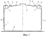
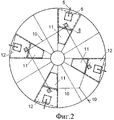
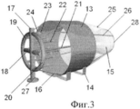
На фиг.1 изображен резервуар, общий вид; на фиг.2 - вид сверху; на фиг.3 - схема пеногенератора, на фиг.4 - схема сопла пеногенератора.Figure 1 shows the tank, a General view; figure 2 is a top view; figure 3 is a diagram of a foam generator, figure 4 is a diagram of a nozzle of a foam generator.
Резервуар (фиг.1 и 2) содержит стенку 1, днище 2, кровлю 3, противопожарные щиты 4, трубы 5 подачи пены внутрь резервуара, пеногенераторы 6 с соплами 7, направленными под разными углами. На щитах также смонтированы люки 8 с крышками 9, к которым прикреплены тяги 10 для их открывания из зоны за пределами обвалования резервуара. Каждый щит также имеет обшивку с ослабленными сварными швами 11 и площадку обслуживания 12, причем толщина обшивки ослабленного участка составляет от 1 до 0,5 толщины обшивки щита.The reservoir (FIGS. 1 and 2) comprises a
Пеногенератор (фиг.3 и 4) состоит из корпуса 13, выполненного в виде цилиндрической обечайки с круговыми ребрами жесткости по краям (на чертеже не показано), продавленными на обечайке в виде окружностей полусферического профиля. Корпус установлен на двух опорных горизонтальных планках 2 с крепежными отверстиями (на чертеже не показано).The foam generator (Figs. 3 and 4) consists of a
С одной стороны к корпусу 13 присоединен распределитель 15 пенораствора посредством, по крайней мере трех, спиц 16, расположенных по образующим усеченной конической поверхности, осесимметричной и соосной цилиндрической обечайке, при этом одним, большим, основанием конической поверхности является основание цилиндрической обечайки корпуса 13, а другим, меньшим, - распределитель 15 пенораствора, который имеет форму соосной цилиндрической обечайке корпуса 13 тороидальной поверхности, соединенной с вертикально расположенным по отношению к горизонтальным планкам 14 входным трубопроводом 17 с фланцем на одном конце и заглушкой на другом (на чертеже не показано). При этом входной трубопровод 17 делит тороидальную поверхность на две симметричные части 19 и 20. Перпендикулярно входному трубопроводу 17 и соосно горизонтальной оси тороидальной поверхности распределителя 15, расположен дополнительный трубопровод 18 с заглушками на обеих концах (на чертеже не показано), вписываемый во внутренний контур тороидальной поверхности распределителя 15, причем диаметры внутренних полостей тороидальной поверхности и входного 17, и дополнительного 18 трубопроводов равны между собой, а сами полости соединены между собой. Причем к внутренним полостям 19 и 20 тороидальной поверхности входного 17 и дополнительного 18 трубопроводов, подсоединены со стороны цилиндрической обечайки корпуса 13 и параллельно ее оси отводы: укороченные 23, средние 22 и длинные 21, заканчивающиеся распылительными соплами 24, ориентированными к направляющему устройству 28.On the one hand, a
Направляющее устройство 28 состоит из внутренней 27 и внешней 25 генерирующих сеток, которые выполнены в виде соосных усеченных конических поверхностей, имеющих одно общее основание в виде первого жесткого кольца круглого профиля, соединенного посредством, по крайней мере трех, спиц 26, расположенных по образующим внешней 25 усеченной конической поверхности, с одним из оснований цилиндрической обечайки корпуса 13. Внутренняя 27 генерирующая сетка имеет второе жесткое кольцо круглого профиля, соединенное с первым жестким кольцом посредством, по крайней мере трех, спиц (на чертеже не показано), расположенных по образующим внутренней 27 усеченной конической поверхности, и расположенное перед основанием цилиндрической обечайки корпуса 13 со стороны, противоположной распределителю 15.The
Каждое из распылительных сопел 24 (фиг.4) состоит из корпуса 29, внутри которого расположен шнек 35, запрессованный в корпус 29. Внешняя поверхность шнека 35 представляет собой, по крайней мере, однозаходную винтовую канавку 36 с правой (или левой) нарезкой.Each of the spray nozzles 24 (FIG. 4) consists of a housing 29, inside of which there is a screw 35, pressed into the housing 29. The outer surface of the screw 35 is at least a one-way screw groove 36 with right (or left) thread.
Подача раствора (жидкости) осуществляется через штуцер 30, закрепленный в верхней части корпуса 29 через герметизирующую прокладку 33. Внутри штуцера 30 выполнено цилиндрическое отверстие 31, переходящее в диффузор 32, который соединен с конической камерой 34, выполненной в корпусе 29, в которую запрессован шнек 35.The supply of the solution (liquid) is carried out through the fitting 30, mounted in the upper part of the housing 29 through the sealing gasket 33. Inside the fitting 30, a cylindrical hole 31 is made, passing into the diffuser 32, which is connected to a conical chamber 34 made in the housing 29, into which the screw is pressed 35.
Пеногенератор устанавливается непосредственно над зоной возможного возгорания, длина создаваемой струи в горизонтальном или вертикальном положении генератора не превышает 1,8 м.The foam generator is installed directly above the zone of possible ignition; the length of the created jet in the horizontal or vertical position of the generator does not exceed 1.8 m.
Пеногенератор работает следующим образом.The foam generator operates as follows.
При возникновении пожара насосная установка (на чертеже не показано) подает раствор пенообразователя из бака-дозатора или пожарной машины во входной трубопровод 17 пеногенератора, откуда он через распределитель 15 пенораствора под давлением подается на отводы 21, 22, 23, сопла 24 которых формируют распыленные струи. Струи с коротких отводов 23 попадают на внешнюю генерирующую сетку 25, а с длинных 21 и средних 22 отводов - на внутреннюю сетку 27.In the event of a fire, a pumping unit (not shown in the drawing) delivers a foaming agent solution from a metering tank or a fire truck to the
Каждое из распылительных сопел 24 работает следующим образом.Each of the
Жидкость подается по цилиндрическому отверстию 31 в диффузор 32, а из него в коническую камеру 34, из которой под давлением поступает в винтовую внешнюю полость шнека 35. Вращающийся поток жидкости во внешней винтовой полости шнека образует вихревое движение, при этом происходит дополнительное дробление капель жидкости за счет турбулизации потока на выходе, и мелкодисперсный вращающийся поток выходит из форсунки с широким вращающимся факелом распыляющейся жидкости (раствора). Шнек 35 форсунки может быть выполнен из твердых материалов: карбида вольфрама, рубина, сапфира.The liquid is supplied through a cylindrical hole 31 into the diffuser 32, and from it into the conical chamber 34, from which it flows under pressure into the screw external cavity of the screw 35. The rotating fluid flow in the external screw cavity of the screw forms a vortex movement, with additional crushing of liquid drops due to turbulization of the outlet stream, and a finely divided rotating stream exits the nozzle with a wide rotating torch of the atomized liquid (solution). The nozzle screw 35 can be made of solid materials: tungsten carbide, ruby, sapphire.
В начале факела распыленная струя раствора пенообразователя имеет наибольшую скорость и при попадании на сетку формируется пена с пузырьками малого размера (2÷3 мм в поперечнике), с удалением от сопла скорость струи падает и далее на сетке формируется пена с более крупными пузырьками (4÷12 мм в поперечнике). Таким образом пеногенератор вырабатывает полидисперсную (разноразмерную по пузырькам) пену, которая обладает свойством быстрого растекания по поверхности.At the beginning of the plume, the sprayed spray of the foaming agent solution has the highest speed and when it gets on the mesh, foam with small bubbles (2 ÷ 3 mm across) is formed, with the distance from the nozzle, the jet velocity drops and then foam with larger bubbles forms on the mesh (4 ÷ 12 mm across). Thus, the foam generator produces polydisperse (differently sized for bubbles) foam, which has the property of rapid spreading over the surface.
Испытания показали, что даже в условиях интенсивного задымления пена образуется в заданных объемах и имеет хорошую устойчивость к распаданию.Tests have shown that even in conditions of intense smoke, foam is formed in predetermined volumes and has good resistance to decay.
В качестве пенообразователя в таких системах пожаротушения применяется фторсинтетический пенообразователь типа "Мультипена". Работает также на 6%-водном растворе фторсодержащего пенообразователя "Подслойный" в условиях задымления помещения.As a foaming agent in such fire extinguishing systems, a fluorosynthetic foaming agent of the "Multipena" type is used. It also works on a 6% aqueous solution of fluorinated foaming agent "Sublayer" in the conditions of smoke in the room.
Пеногенератор предназначен для автоматических систем пожаротушения закрытых технологических помещений (подача пены на место возгорания), где возможно образование паро- и газовоздушных смесей, например, в насосных залах насосных нефтеперекачивающих станций, камерах регулирования давления и т.п.The foam generator is intended for automatic fire extinguishing systems of closed technological rooms (supplying foam to the place of ignition), where vapor and gas mixtures can form, for example, in pump rooms of pumping stations, pressure control chambers, etc.
Пеногенератор работает эффективно при следующих оптимальных параметрах технических характеристик:The foam generator works efficiently with the following optimal technical parameters:
Работа резервуара при аварии сводится к следующему.The operation of the tank during an accident is as follows.
При возникновении аварийной пожарной ситуации внутри резервуара путем дистанционного управления тягой 10 открываются все сблокированные крышки 9 люков 8, благодаря чему сбрасывается избыточное давление внутри резервуара. В случае недостаточного сброса давления через крышки 9 люков 8 происходит раскрытие ослабленных швов участков 11 противопожарных щитов 4.In the event of an emergency fire situation inside the tank by remote control of the
При этом сопла 7 пеногенераторов 6, расположенные под разными углами, обеспечивают покрытие пеной всей поверхности и эффективное гашение пожара. Вместе с тем перенос пеногенераторов 6 со стенки 1 резервуара на его кровлю 3 позволяет увеличить используемый объем резервуара на 10-12%.In this case, the
Преимуществом предлагаемого изобретения являются: предотвращение разрушения конструкций резервуара путем своевременного сброса избыточного давления через крышки и ослабленные участки кровли, более эффективное пожаротушение благодаря рациональной подаче пены на поверхность хранимого продукта, исключение размыва хранимого продукта и увеличение используемого объема резервуара путем переноса пеногенераторов со стенки резервуара на кровлю.An advantage of the invention is: prevention of destruction of reservoir structures by timely overpressure relief through covers and weakened roof sections, more effective fire fighting due to rational supply of foam to the surface of the stored product, elimination of erosion of the stored product and increase in the used volume of the tank by transferring foam generators from the tank wall to the roof .
Claims (1)
Priority Applications (1)
| Application Number | Priority Date | Filing Date | Title |
|---|---|---|---|
| RU2011114253/12A RU2456419C1 (en) | 2011-04-13 | 2011-04-13 | Reservoir for storage of liquid goods |
Applications Claiming Priority (1)
| Application Number | Priority Date | Filing Date | Title |
|---|---|---|---|
| RU2011114253/12A RU2456419C1 (en) | 2011-04-13 | 2011-04-13 | Reservoir for storage of liquid goods |
Publications (1)
| Publication Number | Publication Date |
|---|---|
| RU2456419C1 true RU2456419C1 (en) | 2012-07-20 |
Family
ID=46847432
Family Applications (1)
| Application Number | Title | Priority Date | Filing Date |
|---|---|---|---|
| RU2011114253/12A RU2456419C1 (en) | 2011-04-13 | 2011-04-13 | Reservoir for storage of liquid goods |
Country Status (1)
| Country | Link |
|---|---|
| RU (1) | RU2456419C1 (en) |
Cited By (1)
| Publication number | Priority date | Publication date | Assignee | Title |
|---|---|---|---|---|
| RU2625137C1 (en) * | 2016-06-10 | 2017-07-11 | Олег Савельевич Кочетов | Liquid cargos storage tank |
Citations (3)
| Publication number | Priority date | Publication date | Assignee | Title |
|---|---|---|---|---|
| RU2121048C1 (en) * | 1998-06-16 | 1998-10-27 | Купреишвили Севериан Михайлович | Reservoir for storage of liquid goods |
| RU2128614C1 (en) * | 1996-05-24 | 1999-04-10 | Научно-технический центр экологически чистых технологий | Oil product storage system |
| RU2404834C1 (en) * | 2009-07-20 | 2010-11-27 | Олег Савельевич Кочетов | Foam vortex type |
-
2011
- 2011-04-13 RU RU2011114253/12A patent/RU2456419C1/en active
Patent Citations (3)
| Publication number | Priority date | Publication date | Assignee | Title |
|---|---|---|---|---|
| RU2128614C1 (en) * | 1996-05-24 | 1999-04-10 | Научно-технический центр экологически чистых технологий | Oil product storage system |
| RU2121048C1 (en) * | 1998-06-16 | 1998-10-27 | Купреишвили Севериан Михайлович | Reservoir for storage of liquid goods |
| RU2404834C1 (en) * | 2009-07-20 | 2010-11-27 | Олег Савельевич Кочетов | Foam vortex type |
Cited By (1)
| Publication number | Priority date | Publication date | Assignee | Title |
|---|---|---|---|---|
| RU2625137C1 (en) * | 2016-06-10 | 2017-07-11 | Олег Савельевич Кочетов | Liquid cargos storage tank |
Similar Documents
| Publication | Publication Date | Title |
|---|---|---|
| RU2404834C1 (en) | Foam vortex type | |
| RU2429082C1 (en) | Method and device to extinguish oil and oil products in reservoir | |
| JP5775217B2 (en) | Foam mixing system using compressed air | |
| RU141353U1 (en) | HIGH VELOCITY POLYDISPERSION FOAM GENERATOR | |
| KR101282702B1 (en) | Water mist nozzle for extinguishing fire with water supply hole | |
| CN104147732A (en) | Low-flow water mist sprayer | |
| RU2424839C1 (en) | Fire extinguishing unit | |
| RU2404835C1 (en) | Polydispersity high expansion generator of vortex type | |
| RU2456419C1 (en) | Reservoir for storage of liquid goods | |
| KR101516282B1 (en) | Fire fighting device for helideck | |
| RU2452542C1 (en) | System of fire fighting in vertical reservoirs | |
| RU138822U1 (en) | FIRE EXTINGUISHING SYSTEM IN VERTICAL RESERVOIRS | |
| RU2258549C1 (en) | Method and device for extinguishing fire inside reservoir | |
| RU2625137C1 (en) | Liquid cargos storage tank | |
| RU2552725C1 (en) | Reservoir for storage of liquid goods | |
| RU2547189C1 (en) | Unit for safe oil product storage | |
| RU141070U1 (en) | LIQUID STORAGE TANK | |
| RU2575369C2 (en) | Safe storage device for liquid cargoes | |
| RU2401679C1 (en) | Foam generator of acoustic type | |
| RU148519U1 (en) | FOAM GENERATOR FOR THE TANK FOR SAFE STORAGE OF LIQUID EXPLOSIVE GOODS | |
| RU167825U1 (en) | FIRE EXTINGUISHING MODULE THIN SPRAYED LIQUID | |
| RU2664060C1 (en) | Swirling generator of high-conversion polydisperse foam | |
| RU2425702C1 (en) | Method of fire protection of reservoirs for storage of liquid combustibles and device for its realisation | |
| RU2553956C1 (en) | Fire fighting system in vertical tanks | |
| CN110448825B (en) | Large floating roof tank fire comprehensive fire extinguishing system and fire extinguishing method |