RU2404834C1 - Foam vortex type - Google Patents
Foam vortex type Download PDFInfo
- Publication number
- RU2404834C1 RU2404834C1 RU2009127552/05A RU2009127552A RU2404834C1 RU 2404834 C1 RU2404834 C1 RU 2404834C1 RU 2009127552/05 A RU2009127552/05 A RU 2009127552/05A RU 2009127552 A RU2009127552 A RU 2009127552A RU 2404834 C1 RU2404834 C1 RU 2404834C1
- Authority
- RU
- Russia
- Prior art keywords
- cylindrical shell
- housing
- screw
- toroidal surface
- foam
- Prior art date
Links
Images

Landscapes
- Fire-Extinguishing By Fire Departments, And Fire-Extinguishing Equipment And Control Thereof (AREA)
Abstract
Description
Изобретение относится к области противопожарной техники и предназначено для использования в автоматических системах пожаротушения путем генерация высокократной полидисперсной пены в условиях задымления помещения при блокировании быстрогорящих продуктов высокократной полидисперсной пеной.The invention relates to the field of fire fighting equipment and is intended for use in automatic fire extinguishing systems by generating highly multiple polydisperse foam under conditions of smoke in the room while blocking fast-burning products with high-polydisperse foam.
Наиболее близким техническим решением является пеногенератор, содержащий корпус, распределительное и направляющее устройства (патент РФ №2136389, В05В 1/04, 1998 г. - прототип).The closest technical solution is a foam generator containing a housing, a distribution and a guiding device (RF patent No. 2136389,
Недостатком известного объекта является отсутствие возможности создания оптимальной структуры потока на выходе и недостаточная эффективность и производительность распыления огнетушащего жидкостного раствора пенообразователя (высокократной полидисперсной пены).A disadvantage of the known object is the lack of the ability to create an optimal flow structure at the outlet and the insufficient efficiency and performance of spraying a fire extinguishing liquid solution of a foaming agent (high polydisperse foam).
Технический результат - повышение эффективности распыления огнетушащего жидкостного раствора пенообразователя (высокократной полидисперсной пены).The technical result is an increase in the spraying efficiency of a fire extinguishing liquid solution of a foaming agent (high polydisperse foam).
Это достигается тем, что в пеногенераторе, содержащем корпус, распределительное и направляющее устройства, корпус выполнен в виде цилиндрической обечайки с круговыми ребрами жесткости по краям, продавленными на обечайке в виде окружностей полусферического профиля, и установлен на двух опорных горизонтальных планках с крепежными отверстиями, причем с одной стороны к корпусу присоединен распределитель пенораствора посредством, по крайней мере трех, спиц, расположенных по образующим усеченной конической поверхности, осесимметричной и соосной цилиндрической обечайке, при этом одним, большим, основанием конической поверхности является основание цилиндрической обечайки корпуса, а другим, меньшим, - распределитель пенораствора, который имеет форму соосной цилиндрической обечайке корпуса тороидальной поверхности, соединенной с вертикально расположенным по отношению к горизонтальным планкам входным трубопроводом с фланцем на одном конце и заглушкой на другом, при этом входной трубопровод делит тороидальную поверхность на две симметричные части, а перпендикулярно входному трубопроводу и соосно горизонтальной оси тороидальной поверхности распределителя расположен дополнительный трубопровод с заглушками на обоих концах, вписываемый во внутренний контур тороидальной поверхности распределителя, причем диаметры внутренних полостей тороидальной поверхности и входного и дополнительного трубопроводов равны между собой, а сами полости соединены между собой, а к внутренним полостям тороидальной поверхности, входного и дополнительного трубопроводов, подсоединены со стороны цилиндрической обечайки корпуса и параллельно ее оси отводы: укороченные, средние и длинные, заканчивающиеся специальными соплами, ориентированными к направляющему устройству, которое состоит из внутренней и внешней генерирующих сеток, которые выполнены в виде соосных усеченных конических поверхностей, имеющих одно общее основание в виде первого жесткого кольца круглого профиля, соединенного посредством, по крайней мере трех, спиц, расположенных по образующим внешней усеченной конической поверхности, с одним из оснований цилиндрической обечайки корпуса, причем внутренняя генерирующая сетка имеет второе жесткое кольцо круглого профиля, соединенное с первым жестким кольцом посредством, по крайней мере трех, спиц, расположенных по образующим внутренней усеченной конической поверхности, и расположенное перед основанием цилиндрической обечайки корпуса со стороны, противоположной распределителю, при этом каждое из распылительных сопел содержит корпус со шнеком и штуцер с цилиндрическим отверстием, диффузором и прокладкой, а шнек запрессован в корпус с образованием конической камеры, внешняя поверхность шнека представляет собой, по крайней мере, однозаходную винтовую канавку с правой или левой нарезкой, а шнек форсунки выполнен из твердых материалов: карбида вольфрама, рубина, сапфира.This is achieved by the fact that in a foam generator containing a housing, a distribution and a guiding device, the housing is made in the form of a cylindrical shell with circular stiffening ribs along the edges, squeezed on the shell in the form of circles of a hemispherical profile, and mounted on two horizontal supporting strips with mounting holes, and on the one hand, a foam dispenser is connected to the housing through at least three spokes located along the generatrices of the truncated conical surface, axisymmetric and with axial cylindrical shell, while one larger base of the conical surface is the base of the cylindrical shell of the body, and the other smaller is the foam dispenser, which has the form of a coaxial cylindrical shell of the shell of the toroidal surface, connected to the inlet pipe vertically located relative to the horizontal bars with flange at one end and a plug at the other, while the inlet pipe divides the toroidal surface into two symmetrical parts, and perpendicular to the inlet To the pipe and coaxially with the horizontal axis of the toroidal surface of the distributor there is an additional pipeline with plugs at both ends, inscribed in the inner contour of the toroidal surface of the distributor, the diameters of the internal cavities of the toroidal surface and the inlet and additional pipelines being equal to each other, and the cavities themselves are interconnected, and internal cavities of the toroidal surface, inlet and additional pipelines are connected from the side of the cylindrical shell of the building CA and parallel to its axis taps: shortened, medium and long, ending with special nozzles oriented to the guiding device, which consists of internal and external generating grids, which are made in the form of coaxial truncated conical surfaces having one common base in the form of a first rigid round ring a profile connected by at least three spokes located along the generatrices of the outer truncated conical surface with one of the bases of the cylindrical shell of the housing, the internal generating grid has a second rigid ring of circular profile connected to the first rigid ring by at least three spokes located along the generatrices of the internal truncated conical surface and located in front of the base of the cylindrical shell of the housing from the side opposite to the distributor, each of which is spray nozzles contains a housing with a screw and a fitting with a cylindrical hole, a diffuser and a gasket, and the screw is pressed into the housing with the formation of a conical chamber, an outer surface The screw’s surface is at least a one-way screw groove with right or left thread, and the nozzle screw is made of solid materials: tungsten carbide, ruby, sapphire.
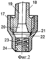
На фиг.1 изображен общий вид пеногенератора вихревого типа, на фиг.2 - схема распылительного сопла.Figure 1 shows a General view of the vortex type foam generator, figure 2 is a diagram of a spray nozzle.
Пеногенератор состоит из корпуса 1, выполненного в виде цилиндрической обечайки с круговыми ребрами жесткости по краям (на чертеже не показано), продавленными на обечайке в виде окружностей полусферического профиля. Корпус установлен на двух опорных горизонтальных планках 2 с крепежными отверстиями (на чертеже не показано).The foam generator consists of a
С одной стороны к корпусу 1 присоединен распределитель 3 пенораствора посредством, по крайней мере трех, спиц 4, расположенных по образующим усеченной конической поверхности, осесимметричной и соосной цилиндрической обечайке, при этом одним, большим, основанием конической поверхности является основание цилиндрической обечайки корпуса 1, а другим, меньшим, - распределитель 3 пенораствора, который имеет форму соосной цилиндрической обечайке корпуса 1 тороидальной поверхности, соединенной с вертикально расположенным по отношению к горизонтальным планкам 2 входным трубопроводом 5 с фланцем на одном конце и заглушкой на другом (на чертеже не показано). При этом входной трубопровод 5 делит тороидальную поверхность на две симметричные части 7 и 8. Перпендикулярно входному трубопроводу 5 и соосно горизонтальной оси тороидальной поверхности распределителя 3 расположен дополнительный трубопровод 6 с заглушками на обоих концах (на чертеже не показано), вписываемый во внутренний контур тороидальной поверхности распределителя 3, причем диаметры внутренних полостей тороидальной поверхности и входного 5 и дополнительного 6 трубопроводов равны между собой, а сами полости соединены между собой. Причем к внутренним полостям 7 и 8 тороидальной поверхности, входного 5 и дополнительного 6 трубопроводов, подсоединены со стороны цилиндрической обечайки корпуса 1 и параллельно ее оси отводы: укороченные 11, средние 10 и длинные 9, заканчивающиеся распылительными соплами 12, ориентированными к направляющему устройству 16.On one side, a foam dispenser 3 is attached to the
Направляющее устройство 16 состоит из внутренней 15 и внешней 13 генерирующих сеток, которые выполнены в виде соосных усеченных конических поверхностей, имеющих одно общее основание в виде первого жесткого кольца круглого профиля, соединенного посредством, по крайней мере трех, спиц 14, расположенных по образующим внешней 13 усеченной конической поверхности, с одним из оснований цилиндрической обечайки корпуса 1. Внутренняя 15 генерирующая сетка имеет второе жесткое кольцо круглого профиля, соединенное с первым жестким кольцом посредством, по крайней мере трех, спиц (на чертеже не показано), расположенных по образующим внутренней 15 усеченной конической поверхности, и расположенное перед основанием цилиндрической обечайки корпуса 1 со стороны, противоположной распределителю 3.The guiding
Каждое из распылительных сопел 12 (фиг.2) состоит из корпуса 17, внутри которого расположен шнек 23, запрессованный в корпус 17. Внешняя поверхность шнека 23 представляет собой, по крайней мере, однозаходную винтовую канавку 24 с правой (или левой) нарезкой.Each of the spray nozzles 12 (FIG. 2) consists of a
Подача раствора (жидкости) осуществляется через штуцер 18, закрепленный в верхней части корпуса 17 через герметизирующую прокладку 21. Внутри штуцера 18 выполнено цилиндрическое отверстие 19, переходящее в диффузор 20, который соединен с конической камерой 22, выполненной в корпусе 17, в которую запрессован шнек 23.The solution (liquid) is supplied through a
Пеногенератор устанавливается непосредственно над зоной возможного возгорания, длина создаваемой струи в горизонтальном или вертикальном положении генератора не превышает 1,8 м.The foam generator is installed directly above the zone of possible ignition; the length of the created jet in the horizontal or vertical position of the generator does not exceed 1.8 m.
Пеногенератор работает следующим образом.The foam generator operates as follows.
При возникновении пожара насосная установка (на чертеже не показано) подает раствор пенообразователя из бака-дозатора или пожарной машины во входной трубопровод 5 пеногенератора, откуда он через распределитель 3 пенораствора под давлением подается на отводы 9, 10, 11, сопла 12 которых формируют распыленные струи. Струи с коротких отводов 11 попадают на внешнюю генерирующую сетку 13, а с длинных 9 и средних 10 отводов - на внутреннюю сетку 15.In the event of a fire, the pumping unit (not shown in the drawing) delivers the foaming agent solution from the metering tank or the fire engine into the
Каждое из распылительных сопел 12 работает следующим образом.Each of the
Жидкость подается по цилиндрическому отверстию 19 в диффузор 20, а из него в коническую камеру 22, из которой под давлением поступает в винтовую внешнюю полость шнека 23. Вращающийся поток жидкости во внешней винтовой полости шнека образует вихревое движение, при этом происходит дополнительное дробление капель жидкости за счет турбулизации потока на выходе, и мелкодисперсный вращающийся поток выходит из форсунки с широким вращающимся факелом распыляющейся жидкости (раствора). Шнек 23 форсунки может быть выполнен из твердых материалов: карбида вольфрама, рубина, сапфира.The liquid is supplied through a
В начале факела распыленная струя раствора пенообразователя имеет наибольшую скорость и при попадании на сетку формируется пена с пузырьками малого размера (2÷3 мм в поперечнике), с удалением от сопла скорость струи падает, и далее на сетке формируется пена с более крупными пузырьками (4÷12 мм в поперечнике). Таким образом пеногенератор вырабатывает полидисперсную (разноразмерную по пузырькам) пену, которая обладает свойством быстрого растекания по поверхности.At the beginning of the torch, the sprayed spray of the foaming agent solution has the highest speed and, when it gets on the mesh, foam with small bubbles (2 ÷ 3 mm across) is formed, with the distance from the nozzle, the jet velocity drops, and then foam with larger bubbles forms on the mesh (4 ÷ 12 mm across). Thus, the foam generator produces polydisperse (differently sized for bubbles) foam, which has the property of rapid spreading over the surface.
Испытания показали, что даже в условиях интенсивного задымления пена образуется в заданных объемах и имеет хорошую устойчивость к распаданию.Tests have shown that even in conditions of intense smoke, foam is formed in predetermined volumes and has good resistance to decay.
В качестве пенообразователя в таких системах пожаротушения применяется фторсинтетический пенообразователь типа "Мультипена". Работает также на 6%-водном растворе фторсодержащего пенообразователя "Подслойный" в условиях задымления помещения.As a foaming agent in such fire extinguishing systems, a fluorosynthetic foaming agent of the "Multipena" type is used. It also works on a 6% aqueous solution of fluorinated foaming agent "Sublayer" under conditions of smoke in the room.
Пеногенератор предназначен для автоматических систем пожаротушения закрытых технологических помещений (подача пены на место возгорания), где возможно образование паро- и газовоздушных смесей, например, в насосных залах насосных нефтеперекачивающих станций, камерах регулирования давления и т.п.The foam generator is intended for automatic fire extinguishing systems of closed technological rooms (supplying foam to the place of ignition), where vapor and gas mixtures can form, for example, in pump rooms of pumping stations, pressure control chambers, etc.
Пеногенератор работает эффективно при следующих оптимальных параметрах технических характеристик:The foam generator works efficiently with the following optimal technical parameters:
Claims (1)
Priority Applications (1)
| Application Number | Priority Date | Filing Date | Title |
|---|---|---|---|
| RU2009127552/05A RU2404834C1 (en) | 2009-07-20 | 2009-07-20 | Foam vortex type |
Applications Claiming Priority (1)
| Application Number | Priority Date | Filing Date | Title |
|---|---|---|---|
| RU2009127552/05A RU2404834C1 (en) | 2009-07-20 | 2009-07-20 | Foam vortex type |
Publications (1)
| Publication Number | Publication Date |
|---|---|
| RU2404834C1 true RU2404834C1 (en) | 2010-11-27 |
Family
ID=44057544
Family Applications (1)
| Application Number | Title | Priority Date | Filing Date |
|---|---|---|---|
| RU2009127552/05A RU2404834C1 (en) | 2009-07-20 | 2009-07-20 | Foam vortex type |
Country Status (1)
| Country | Link |
|---|---|
| RU (1) | RU2404834C1 (en) |
Cited By (8)
| Publication number | Priority date | Publication date | Assignee | Title |
|---|---|---|---|---|
| RU2450839C1 (en) * | 2011-05-19 | 2012-05-20 | Олег Савельевич Кочетов | Plant to supply fire-quenching fluid |
| RU2456419C1 (en) * | 2011-04-13 | 2012-07-20 | Олег Савельевич Кочетов | Reservoir for storage of liquid goods |
| RU2479333C1 (en) * | 2012-04-10 | 2013-04-20 | Олег Савельевич Кочетов | Vortex foam generator of kochetov |
| RU2490040C1 (en) * | 2012-03-20 | 2013-08-20 | Олег Савельевич Кочетов | Mobile fire-extinguishing plant |
| RU2494779C1 (en) * | 2012-09-20 | 2013-10-10 | Олег Савельевич Кочетов | Foam generator of vortex type |
| RU2545230C1 (en) * | 2013-12-26 | 2015-03-27 | Федеральное государственное бюджетное учреждение "Всероссийский научно-исследовательский институт по проблемам гражданской обороны и чрезвычайных ситуаций МЧС России" (федеральный центр науки и высоких технологий) | Device for fast recovery of asphalt-concrete road pavement in case of its failure as result of emergency situation |
| CN109876336A (en) * | 2019-03-06 | 2019-06-14 | 沃斧(上海)安防科技有限公司 | A kind of high power foam generator |
| CN111346328A (en) * | 2020-03-09 | 2020-06-30 | 安徽建筑大学 | Water mist fire extinguishing device for horizontal pipeline gas jet fire |
-
2009
- 2009-07-20 RU RU2009127552/05A patent/RU2404834C1/en active
Cited By (9)
| Publication number | Priority date | Publication date | Assignee | Title |
|---|---|---|---|---|
| RU2456419C1 (en) * | 2011-04-13 | 2012-07-20 | Олег Савельевич Кочетов | Reservoir for storage of liquid goods |
| RU2450839C1 (en) * | 2011-05-19 | 2012-05-20 | Олег Савельевич Кочетов | Plant to supply fire-quenching fluid |
| RU2490040C1 (en) * | 2012-03-20 | 2013-08-20 | Олег Савельевич Кочетов | Mobile fire-extinguishing plant |
| RU2479333C1 (en) * | 2012-04-10 | 2013-04-20 | Олег Савельевич Кочетов | Vortex foam generator of kochetov |
| RU2494779C1 (en) * | 2012-09-20 | 2013-10-10 | Олег Савельевич Кочетов | Foam generator of vortex type |
| RU2545230C1 (en) * | 2013-12-26 | 2015-03-27 | Федеральное государственное бюджетное учреждение "Всероссийский научно-исследовательский институт по проблемам гражданской обороны и чрезвычайных ситуаций МЧС России" (федеральный центр науки и высоких технологий) | Device for fast recovery of asphalt-concrete road pavement in case of its failure as result of emergency situation |
| CN109876336A (en) * | 2019-03-06 | 2019-06-14 | 沃斧(上海)安防科技有限公司 | A kind of high power foam generator |
| CN111346328A (en) * | 2020-03-09 | 2020-06-30 | 安徽建筑大学 | Water mist fire extinguishing device for horizontal pipeline gas jet fire |
| CN111346328B (en) * | 2020-03-09 | 2021-12-21 | 安徽建筑大学 | Water mist fire extinguishing device for horizontal pipeline gas jet fire |
Similar Documents
| Publication | Publication Date | Title |
|---|---|---|
| RU2404834C1 (en) | Foam vortex type | |
| RU2427402C1 (en) | Kochetov's sprayer | |
| RU141353U1 (en) | HIGH VELOCITY POLYDISPERSION FOAM GENERATOR | |
| RU2428235C1 (en) | Kochetov's vortex sprayer | |
| RU2450837C1 (en) | Foam generator of ejection type | |
| RU2448750C1 (en) | Foam generator | |
| RU2647104C2 (en) | Finely divided liquid sprayer | |
| RU2646675C2 (en) | Finely divided liquid sprayer | |
| RU2451560C1 (en) | Foam generator of ejection type with vortical sprayer | |
| RU2404835C1 (en) | Polydispersity high expansion generator of vortex type | |
| RU2422215C1 (en) | Fire extinguisher spraying nozzle | |
| RU2664060C1 (en) | Swirling generator of high-conversion polydisperse foam | |
| RU2456042C1 (en) | Foamgenerator of ejection type | |
| RU2494779C1 (en) | Foam generator of vortex type | |
| RU2455080C1 (en) | Foam generator | |
| RU2551063C1 (en) | Fluid sprayer | |
| RU2642582C1 (en) | Foam generator | |
| RU2456041C1 (en) | Sprayer | |
| RU2450840C1 (en) | Foam generator | |
| RU2536400C1 (en) | Kochetov's foam generator | |
| RU2451559C1 (en) | Vortical foam generator of ejection type | |
| RU2404833C1 (en) | Generator of polydispersity foam | |
| RU2551733C1 (en) | Kochetov's fluid fine sprayer | |
| RU2502565C1 (en) | Swirling generator of high-conversion polydisperse foam | |
| RU2641272C1 (en) | Generator of polydispersed high-quality foam of vortex type |