RU2642582C1 - Foam generator - Google Patents
Foam generator Download PDFInfo
- Publication number
- RU2642582C1 RU2642582C1 RU2017106137A RU2017106137A RU2642582C1 RU 2642582 C1 RU2642582 C1 RU 2642582C1 RU 2017106137 A RU2017106137 A RU 2017106137A RU 2017106137 A RU2017106137 A RU 2017106137A RU 2642582 C1 RU2642582 C1 RU 2642582C1
- Authority
- RU
- Russia
- Prior art keywords
- housing
- cylindrical shell
- conical
- foam
- shell
- Prior art date
Links
Images
Classifications
-
- A—HUMAN NECESSITIES
- A62—LIFE-SAVING; FIRE-FIGHTING
- A62C—FIRE-FIGHTING
- A62C31/00—Delivery of fire-extinguishing material
- A62C31/02—Nozzles specially adapted for fire-extinguishing
- A62C31/12—Nozzles specially adapted for fire-extinguishing for delivering foam or atomised foam
-
- B—PERFORMING OPERATIONS; TRANSPORTING
- B05—SPRAYING OR ATOMISING IN GENERAL; APPLYING FLUENT MATERIALS TO SURFACES, IN GENERAL
- B05B—SPRAYING APPARATUS; ATOMISING APPARATUS; NOZZLES
- B05B1/00—Nozzles, spray heads or other outlets, with or without auxiliary devices such as valves, heating means
- B05B1/34—Nozzles, spray heads or other outlets, with or without auxiliary devices such as valves, heating means designed to influence the nature of flow of the liquid or other fluent material, e.g. to produce swirl
- B05B1/3405—Nozzles, spray heads or other outlets, with or without auxiliary devices such as valves, heating means designed to influence the nature of flow of the liquid or other fluent material, e.g. to produce swirl to produce swirl
Abstract
Description
Изобретение относится к области противопожарной техники и предназначено для использования в автоматических системах пожаротушения путем генерации высокократной полидисперсной пены в условиях задымления помещения при блокировании быстрогорящих продуктов высокократной полидисперсной пеной.The invention relates to the field of fire fighting equipment and is intended for use in automatic fire extinguishing systems by generating highly multiple polydisperse foam under conditions of smoke in the room while blocking fast-burning products with high-polydisperse foam.
Наиболее близким техническим решением является пеногенератор, содержащий корпус, распределительное и направляющее устройства (патент РФ №2455080 - прототип).The closest technical solution is a foam generator containing a housing, a distribution and a guiding device (RF patent No. 2455080 - prototype).
Недостатком известного объекта является отсутствие возможности создания оптимальной структуры потока на выходе и недостаточная эффективность и производительность распыления огнетушащего жидкостного раствора пенообразователя (высокократной полидисперсной пены).A disadvantage of the known object is the lack of the ability to create an optimal flow structure at the outlet and the insufficient efficiency and performance of spraying a fire extinguishing liquid solution of a foaming agent (high polydisperse foam).
Технический результат - повышение эффективности распыления огнетушащего жидкостного раствора пенообразователя (высокократной полидисперсной пены).The technical result is an increase in the spraying efficiency of a fire extinguishing liquid solution of a foaming agent (high polydisperse foam).
Это достигается тем, что в пеногенераторе, содержащим корпус, распределительное и направляющее устройства, корпус выполнен в виде цилиндрической обечайки с круговыми ребрами жесткости по краям, продавленными на обечайке в виде окружностей полусферического профиля, и установлен на двух опорных горизонтальных планках с крепежными отверстиями, причем с одной стороны к корпусу присоединен распределитель пенораствора посредством по крайней мере трех спиц, расположенных по образующим усеченной конической поверхности, осесимметричной и соосной цилиндрической обечайке, при этом одним, большим, основанием конической поверхности является основание цилиндрической обечайки корпуса, а другим, меньшим, - распределитель пенораствора, который имеет форму соосной цилиндрической обечайке корпуса тороидальной поверхности, соединенной с вертикально расположенным по отношению к горизонтальным планкам входным трубопроводом с фланцем на одном конце и заглушкой на другом, при этом входной трубопровод делит тороидальную поверхность на две симметричные части, а перпендикулярно входному трубопроводу и соосно горизонтальной оси тороидальной поверхности распределителя расположен дополнительный трубопровод с заглушками на обоих концах, вписываемый во внутренний контур тороидальной поверхности распределителя, причем диаметры внутренних полостей тороидальной поверхности и входного, и дополнительного трубопроводов равны между собой, а сами полости соединены между собой, а к внутренним полостям тороидальной поверхности входного и дополнительного трубопроводов подсоединены со стороны цилиндрической обечайки корпуса и параллельно ее оси отводы: укороченные, средние и длинные, заканчивающиеся распылительными соплами, ориентированными к направляющему устройству, которое состоит из внутренней и внешней генерирующих сеток, которые выполнены в виде соосных усеченных конических поверхностей, имеющих одно общее основание в виде первого жесткого кольца круглого профиля, соединенного посредством по крайней мере трех спиц, расположенных по образующим внешней усеченной конической поверхности, с одним из оснований цилиндрической обечайки корпуса, причем внутренняя генерирующая сетка имеет второе жесткое кольцо круглого профиля, соединенное с первым жестким кольцом посредством по крайней мере трех спиц, расположенных по образующим внутренней усеченной конической поверхности, и расположенное перед основанием цилиндрической обечайки корпуса со стороны, противоположной распределителю, каждое из распылительных сопел состоит из цилиндрического полого корпуса с каналом для подвода жидкости, резьбовым участком и пояском со срезами под ключ, а в нижней части цилиндрического полого корпуса с каналом для подвода жидкости, закреплен полый конический завихритель, коническая обечайка которого фиксируется посредством по крайней мере трех спиц, закрепленных одним концом на конической обечайке завихрителя, в ее верхней части, а другим концом - в кольцевой канавке, выполненной на внутренней поверхности канала для подвода жидкости, при этом на внешней поверхности полого конического завихрителя выполнена сквозная винтовая нарезка.This is achieved by the fact that in a foam generator containing a housing, a distribution and a guiding device, the housing is made in the form of a cylindrical shell with circular stiffeners along the edges, pressed on the shell in the form of circles of a hemispherical profile, and mounted on two horizontal supporting strips with mounting holes, and on the one hand, a foam dispenser is attached to the housing through at least three spokes located along the generatrices of the truncated conical surface, axisymmetric and with an axial cylindrical shell, with one large base of the conical surface being the base of the cylindrical shell of the body, and the other smaller is the foam dispenser, which has the form of a coaxial cylindrical shell of the body of the toroidal surface, connected to the inlet pipe vertically located relative to the horizontal bars with a flange at one end and a plug at the other, while the inlet pipe divides the toroidal surface into two symmetrical parts, and perpendicular to the inlet An additional pipeline with plugs at both ends is arranged coaxially with the horizontal axis of the toroidal surface of the distributor and fits into the inner contour of the toroidal surface of the distributor; moreover, the diameters of the internal cavities of the toroidal surface and the input and additional pipelines are equal to each other, and the cavities themselves are interconnected, and to the internal cavities of the toroidal surface of the inlet and additional pipelines are connected from the side of the cylindrical shell and bends parallel to its axis: shortened, medium and long, ending with spray nozzles oriented to a guiding device, which consists of internal and external generating grids, which are made in the form of coaxial truncated conical surfaces having one common base in the form of a first rigid circular ring a profile connected by at least three spokes located along the generators of the external truncated conical surface with one of the bases of the cylindrical shell of the housing, the internal generating grid has a second rigid ring of circular profile connected to the first rigid ring by at least three spokes located along the generatrices of the internal truncated conical surface and located in front of the base of the cylindrical shell of the housing on the side opposite to the distributor, each of the spray nozzles consists of a cylindrical hollow body with a channel for supplying fluid, a threaded section and a belt with turn-key sections, and in the lower part of the cylindrical hollow body a hollow conical swirl is fixed to the fluid supply channel, the conical shell of which is fixed by means of at least three spokes fixed at one upper end to the swirl conical shell and the other end to an annular groove made on the inner surface of the fluid supply channel , while on the outer surface of the hollow conical swirl made through screw thread.
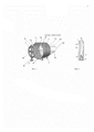
На фиг. 1 изображен общий вид пеногенератора, на фиг. 2 - схема распылительного сопла.In FIG. 1 shows a general view of the foam generator, FIG. 2 is a diagram of a spray nozzle.
Пеногенератор состоит из корпуса 1, выполненного в виде цилиндрической обечайки с круговыми ребрами жесткости по краям (не показано), продавленными на обечайке в виде окружностей полусферического профиля. Корпус установлен на двух опорных горизонтальных планках 2 с крепежными отверстиями (не показано).The foam generator consists of a
С одной стороны к корпусу 1 присоединен распределитель 3 пенораствора посредством по крайней мере трех спиц 4, расположенных по образующим усеченной конической поверхности, осесимметричной и соосной цилиндрической обечайке, при этом одним, большим, основанием конической поверхности является основание цилиндрической обечайки корпуса 1, а другим, меньшим, - распределитель 3 пенораствора, который имеет форму соосной цилиндрической обечайке корпуса 1 тороидальной поверхности, соединенной с вертикально расположенным по отношению к горизонтальным планкам 2 входным трубопроводом 5 с фланцем на одном конце и заглушкой на другом (не показано). При этом входной трубопровод 5 делит тороидальную поверхность на две симметричные части 7 и 8. Перпендикулярно входному трубопроводу 5 и соосно горизонтальной оси тороидальной поверхности распределителя 3 расположен дополнительный трубопровод 6 с заглушками на обоих концах (не показано), вписываемый во внутренний контур тороидальной поверхности распределителя 3, причем диаметры внутренних полостей тороидальной поверхности и входного 5, и дополнительного 6 трубопроводов равны между собой, а сами полости соединены между собой. Причем к внутренним полостям 7 и 8 тороидальной поверхности входного 5 и дополнительного 6 трубопроводов подсоединены со стороны цилиндрической обечайки корпуса 1 и параллельно ее оси отводы: укороченные 11, средние 10 и длинные 9, заканчивающиеся распылительными соплами 12, ориентированными к направляющему устройству 16.On one side, a
Направляющее устройство 16 состоит из внутренней 15 и внешней 13 генерирующих сеток, которые выполнены в виде соосных усеченных конических поверхностей, имеющих одно общее основание в виде первого жесткого кольца круглого профиля, соединенного посредством по крайней мере трех спиц 14, расположенных по образующим внешней 13 усеченной конической поверхности, с одним из оснований цилиндрической обечайки корпуса 1. Внутренняя 15 генерирующая сетка имеет второе жесткое кольцо круглого профиля, соединенное с первым жестким кольцом посредством по крайней мере трех спиц (не показано), расположенных по образующим внутренней 15 усеченной конической поверхности, и расположенное перед основанием цилиндрической обечайки корпуса 1 со стороны, противоположной распределителю 3.The
Каждое из распылительных сопел 12 (фиг. 2) состоит из цилиндрического полого корпуса 20 с каналом 18 для подвода жидкости, резьбовым участком 17 и пояском 19 со срезами под ключ. В нижней части канала 18 для подвода жидкости закреплен полый конический завихритель 21, коническая обечайка 23 которого фиксируется посредством по крайней мере трех спиц 22, закрепленных одним концом на конической обечайке завихрителя, в ее верхней части, а другим концом - в кольцевой канавке канала 18 (не показано), выполненной на его внутренней поверхности. На внешней поверхности полого конического завихрителя 21 выполнена сквозная винтовая нарезка.Each of the spray nozzles 12 (Fig. 2) consists of a cylindrical
Работа распылительных сопел осуществляется следующим образом.The operation of the spray nozzles is as follows.
Жидкость под давлением подается в полость канала 18 для подвода жидкости корпуса 20 сопла, а затем в нижнюю часть канала 18, и через конический завихритель 21, выходит наружу, образуя мелкодисперсный поток жидкости.Liquid under pressure is supplied to the cavity of the
Использование распылительных сопел описанной конструкции позволяет получить равномерный по объему поток капель мелкодисперсного распыла в диапазоне диаметров капель от 30 до 150 мкм при давлении подачи воды не более 1 МПа.The use of spray nozzles of the described design makes it possible to obtain a uniformly flowing stream of finely dispersed droplets in the range of droplet diameters from 30 to 150 microns at a water supply pressure of not more than 1 MPa.
Пеногенератор устанавливается непосредственно над зоной возможного возгорания, длина создаваемой струи в горизонтальном или вертикальном положении генератора не превышает 1,8 м.The foam generator is installed directly above the zone of possible ignition; the length of the created jet in the horizontal or vertical position of the generator does not exceed 1.8 m.
Пеногенератор работает следующим образом.The foam generator operates as follows.
При возникновении пожара насосная установка (на чертеже не показано) подает раствор пенообразователя из бака-дозатора или пожарной машины во входной трубопровод 5 пеногенератора, откуда он через распределитель 3 пенораствора под давлением подается на отводы 9, 10, 11, сопла 12 которых формируют распыленные струи. Струи с коротких отводов 11 попадают на внешнюю генерирующую сетку 13, а с длинных 9 и средних 10 отводов - на внутреннюю сетку 15.In the event of a fire, a pumping unit (not shown in the drawing) delivers a foaming agent solution from a metering tank or a fire truck to the
Каждое из распылительных сопел 12 работает следующим образом.Each of the
Жидкость подается по цилиндрическому дросселирующему отверстию 18 в коническое 19, являющееся диффузором, увеличивающим дробление капель жидкости за счет турбулизации потока на выходе. В начале факела распыленная струя раствора пенообразователя имеет наибольшую скорость и при попадании на сетку формируется пена с пузырьками малого размера (2÷3 мм в поперечнике), с удалением от сопла скорость струи падает и далее на сетке формируется пена с более крупными пузырьками (4÷12 мм в поперечнике). Таким образом пеногенератор вырабатывает полидисперсную (разноразмерную по пузырькам) пену, которая обладает свойством быстрого растекания по поверхности.The fluid is supplied through a
Испытания показали, что даже в условиях интенсивного задымления пена образуется в заданных объемах и имеет хорошую устойчивость к распаданию.Tests have shown that even in conditions of intense smoke, foam is formed in predetermined volumes and has good resistance to decay.
В качестве пенообразователя в таких системах пожаротушения применяется фторсинтетический пенообразователь типа "Мультипена". Работает также на 6%-водном растворе фторсодержащего пенообразователя "Подслойный" в условиях задымления помещения.As a foaming agent in such fire extinguishing systems, a fluorosynthetic foaming agent of the "Multipena" type is used. It also works on a 6% aqueous solution of fluorinated foaming agent "Sublayer" in the conditions of smoke in the room.
Пеногенератор предназначен для автоматических систем пожаротушения закрытых технологических помещений (подача пены на место возгорания), где возможно образование паро- и газовоздушных смесей, например, в насосных залах насосных нефтеперекачивающих станций, камерах регулирования давления и т.п.The foam generator is intended for automatic fire extinguishing systems of closed technological rooms (supplying foam to the place of ignition), where vapor and gas mixtures can form, for example, in pump rooms of pumping stations, pressure control chambers, etc.
Пеногенератор работает эффективно при следующих оптимальных параметрах технических характеристик:The foam generator works efficiently with the following optimal technical parameters:
Claims (1)
Priority Applications (1)
| Application Number | Priority Date | Filing Date | Title |
|---|---|---|---|
| RU2017106137A RU2642582C1 (en) | 2017-02-27 | 2017-02-27 | Foam generator |
Applications Claiming Priority (1)
| Application Number | Priority Date | Filing Date | Title |
|---|---|---|---|
| RU2017106137A RU2642582C1 (en) | 2017-02-27 | 2017-02-27 | Foam generator |
Publications (1)
| Publication Number | Publication Date |
|---|---|
| RU2642582C1 true RU2642582C1 (en) | 2018-01-25 |
Family
ID=61023916
Family Applications (1)
| Application Number | Title | Priority Date | Filing Date |
|---|---|---|---|
| RU2017106137A RU2642582C1 (en) | 2017-02-27 | 2017-02-27 | Foam generator |
Country Status (1)
| Country | Link |
|---|---|
| RU (1) | RU2642582C1 (en) |
Citations (6)
| Publication number | Priority date | Publication date | Assignee | Title |
|---|---|---|---|---|
| FR2309283A1 (en) * | 1975-05-02 | 1976-11-26 | Menet Jean | Fire fighting water delivery nozzle - has movable portion on free end for jet or spray |
| US5992529A (en) * | 1996-12-16 | 1999-11-30 | Williams Fire & Hazard Control, Inc. | Mixing passage in a foam fire fighting nozzle |
| RU2183487C2 (en) * | 2000-07-06 | 2002-06-20 | Мелкозеров Владимир Максимович | Portable apparatus for producing and applying foamed self-hardening polymer composition |
| RU54825U1 (en) * | 2006-02-14 | 2006-07-27 | Андрей Леонидович Душкин | LIQUID SPRAY |
| WO2006132557A1 (en) * | 2005-06-05 | 2006-12-14 | Telesto Sp. Z O.O. | Fire extinguishing device and extinguishing head |
| RU2455080C1 (en) * | 2011-05-19 | 2012-07-10 | Олег Савельевич Кочетов | Foam generator |
-
2017
- 2017-02-27 RU RU2017106137A patent/RU2642582C1/en active
Patent Citations (6)
| Publication number | Priority date | Publication date | Assignee | Title |
|---|---|---|---|---|
| FR2309283A1 (en) * | 1975-05-02 | 1976-11-26 | Menet Jean | Fire fighting water delivery nozzle - has movable portion on free end for jet or spray |
| US5992529A (en) * | 1996-12-16 | 1999-11-30 | Williams Fire & Hazard Control, Inc. | Mixing passage in a foam fire fighting nozzle |
| RU2183487C2 (en) * | 2000-07-06 | 2002-06-20 | Мелкозеров Владимир Максимович | Portable apparatus for producing and applying foamed self-hardening polymer composition |
| WO2006132557A1 (en) * | 2005-06-05 | 2006-12-14 | Telesto Sp. Z O.O. | Fire extinguishing device and extinguishing head |
| RU54825U1 (en) * | 2006-02-14 | 2006-07-27 | Андрей Леонидович Душкин | LIQUID SPRAY |
| RU2455080C1 (en) * | 2011-05-19 | 2012-07-10 | Олег Савельевич Кочетов | Foam generator |
Similar Documents
| Publication | Publication Date | Title |
|---|---|---|
| RU2427402C1 (en) | Kochetov's sprayer | |
| RU2404834C1 (en) | Foam vortex type | |
| RU2428235C1 (en) | Kochetov's vortex sprayer | |
| RU141353U1 (en) | HIGH VELOCITY POLYDISPERSION FOAM GENERATOR | |
| RU2450837C1 (en) | Foam generator of ejection type | |
| RU2647104C2 (en) | Finely divided liquid sprayer | |
| RU2448750C1 (en) | Foam generator | |
| RU2646675C2 (en) | Finely divided liquid sprayer | |
| RU2474452C1 (en) | Fluid sprayer | |
| RU2615256C1 (en) | Fine-dispersed liquid sprayer | |
| RU2616891C1 (en) | Nozzle | |
| RU2451560C1 (en) | Foam generator of ejection type with vortical sprayer | |
| RU2664060C1 (en) | Swirling generator of high-conversion polydisperse foam | |
| RU2456042C1 (en) | Foamgenerator of ejection type | |
| RU2494779C1 (en) | Foam generator of vortex type | |
| RU2642582C1 (en) | Foam generator | |
| RU2551063C1 (en) | Fluid sprayer | |
| RU2455080C1 (en) | Foam generator | |
| RU2456041C1 (en) | Sprayer | |
| RU2551733C1 (en) | Kochetov's fluid fine sprayer | |
| RU2642581C1 (en) | Foam generator of ejection type | |
| RU2641272C1 (en) | Generator of polydispersed high-quality foam of vortex type | |
| RU2536400C1 (en) | Kochetov's foam generator | |
| RU2646721C1 (en) | Fluid sprayer | |
| RU2642647C1 (en) | Foaming generator with a mesh cutter |