RU2422331C2 - Section of gondola air intake edge with electric ice protection and acoustic absorption zone - Google Patents
Section of gondola air intake edge with electric ice protection and acoustic absorption zone Download PDFInfo
- Publication number
- RU2422331C2 RU2422331C2 RU2008141473/11A RU2008141473A RU2422331C2 RU 2422331 C2 RU2422331 C2 RU 2422331C2 RU 2008141473/11 A RU2008141473/11 A RU 2008141473/11A RU 2008141473 A RU2008141473 A RU 2008141473A RU 2422331 C2 RU2422331 C2 RU 2422331C2
- Authority
- RU
- Russia
- Prior art keywords
- section
- edge
- air intake
- heating element
- electric heating
- Prior art date
Links
Images
Classifications
-
- B—PERFORMING OPERATIONS; TRANSPORTING
- B64—AIRCRAFT; AVIATION; COSMONAUTICS
- B64D—EQUIPMENT FOR FITTING IN OR TO AIRCRAFT; FLIGHT SUITS; PARACHUTES; ARRANGEMENTS OR MOUNTING OF POWER PLANTS OR PROPULSION TRANSMISSIONS IN AIRCRAFT
- B64D15/00—De-icing or preventing icing on exterior surfaces of aircraft
- B64D15/12—De-icing or preventing icing on exterior surfaces of aircraft by electric heating
-
- B—PERFORMING OPERATIONS; TRANSPORTING
- B64—AIRCRAFT; AVIATION; COSMONAUTICS
- B64D—EQUIPMENT FOR FITTING IN OR TO AIRCRAFT; FLIGHT SUITS; PARACHUTES; ARRANGEMENTS OR MOUNTING OF POWER PLANTS OR PROPULSION TRANSMISSIONS IN AIRCRAFT
- B64D33/00—Arrangements in aircraft of power plant parts or auxiliaries not otherwise provided for
- B64D33/02—Arrangements in aircraft of power plant parts or auxiliaries not otherwise provided for of combustion air intakes
-
- F—MECHANICAL ENGINEERING; LIGHTING; HEATING; WEAPONS; BLASTING
- F02—COMBUSTION ENGINES; HOT-GAS OR COMBUSTION-PRODUCT ENGINE PLANTS
- F02C—GAS-TURBINE PLANTS; AIR INTAKES FOR JET-PROPULSION PLANTS; CONTROLLING FUEL SUPPLY IN AIR-BREATHING JET-PROPULSION PLANTS
- F02C7/00—Features, components parts, details or accessories, not provided for in, or of interest apart form groups F02C1/00 - F02C6/00; Air intakes for jet-propulsion plants
- F02C7/04—Air intakes for gas-turbine plants or jet-propulsion plants
- F02C7/047—Heating to prevent icing
-
- H—ELECTRICITY
- H05—ELECTRIC TECHNIQUES NOT OTHERWISE PROVIDED FOR
- H05B—ELECTRIC HEATING; ELECTRIC LIGHT SOURCES NOT OTHERWISE PROVIDED FOR; CIRCUIT ARRANGEMENTS FOR ELECTRIC LIGHT SOURCES, IN GENERAL
- H05B3/00—Ohmic-resistance heating
- H05B3/20—Heating elements having extended surface area substantially in a two-dimensional plane, e.g. plate-heater
- H05B3/22—Heating elements having extended surface area substantially in a two-dimensional plane, e.g. plate-heater non-flexible
- H05B3/26—Heating elements having extended surface area substantially in a two-dimensional plane, e.g. plate-heater non-flexible heating conductor mounted on insulating base
- H05B3/267—Heating elements having extended surface area substantially in a two-dimensional plane, e.g. plate-heater non-flexible heating conductor mounted on insulating base the insulating base being an organic material, e.g. plastic
-
- B—PERFORMING OPERATIONS; TRANSPORTING
- B64—AIRCRAFT; AVIATION; COSMONAUTICS
- B64D—EQUIPMENT FOR FITTING IN OR TO AIRCRAFT; FLIGHT SUITS; PARACHUTES; ARRANGEMENTS OR MOUNTING OF POWER PLANTS OR PROPULSION TRANSMISSIONS IN AIRCRAFT
- B64D33/00—Arrangements in aircraft of power plant parts or auxiliaries not otherwise provided for
- B64D33/02—Arrangements in aircraft of power plant parts or auxiliaries not otherwise provided for of combustion air intakes
- B64D2033/0233—Arrangements in aircraft of power plant parts or auxiliaries not otherwise provided for of combustion air intakes comprising de-icing means
-
- Y—GENERAL TAGGING OF NEW TECHNOLOGICAL DEVELOPMENTS; GENERAL TAGGING OF CROSS-SECTIONAL TECHNOLOGIES SPANNING OVER SEVERAL SECTIONS OF THE IPC; TECHNICAL SUBJECTS COVERED BY FORMER USPC CROSS-REFERENCE ART COLLECTIONS [XRACs] AND DIGESTS
- Y02—TECHNOLOGIES OR APPLICATIONS FOR MITIGATION OR ADAPTATION AGAINST CLIMATE CHANGE
- Y02T—CLIMATE CHANGE MITIGATION TECHNOLOGIES RELATED TO TRANSPORTATION
- Y02T50/00—Aeronautics or air transport
- Y02T50/60—Efficient propulsion technologies, e.g. for aircraft
Abstract
Description
Настоящее изобретение относится к секции кромки воздухозаборника гондолы турбореактивного двигателя, имеющей наружную обшивку, обращенную наружу кромки, и внутреннюю обшивку, обращенную внутрь кромки.The present invention relates to a section of an edge of an air intake of a nacelle of a turbojet having an outer skin facing outward of the edge and an inner skin facing inward of the edge.
Сила тяги самолета обеспечивается одной или несколькими силовыми установками, в состав которых входит турбореактивный двигатель, расположенный в цилиндрической гондоле. Каждая силовая установка крепится к самолету посредством пилона, находящегося, как правило, под крылом или на уровне фюзеляжа.The thrust force of the aircraft is provided by one or more power plants, which include a turbojet engine located in a cylindrical nacelle. Each power plant is attached to the aircraft by means of a pylon, usually located under the wing or at the level of the fuselage.
Конструкция гондолы обычно содержит воздухозаборник, расположенный по потоку перед двигателем, среднюю часть, охватывающую вентилятор турбореактивного двигателя, и заднюю по потоку часть, которая вмещает устройство реверса тяги и окружает камеру сгорания турбореактивного двигателя, и заканчивается, как правило, реактивным соплом, выходное отверстие которого располагается за турбореактивным двигателем.The nacelle’s construction usually comprises an air intake located upstream of the engine, a middle part covering the fan of the turbojet engine, and a rear part, which accommodates the thrust reverser and surrounds the combustion chamber of the turbojet engine, and usually ends with a jet nozzle, the outlet of which located behind the turbojet engine.
Воздухозаборник содержит с одной стороны кромку воздухозаборника, выполненную таким образом, чтобы воздух, подаваемый на вентилятор и внутренние компрессоры, поступал в направлении турбореактивного двигателя, необходимого для питания его вентилятора и внутренних компрессоров, а с другой стороны задний по потоку элемент, к которому крепится указанная кромка и который обеспечивает надлежащий отвод воздуха в сторону лопастей вентилятора. Весь этот узел крепится по потоку перед кожухом вентилятора, являющегося составной частью передней по потоку части гондолы.The air intake contains on one side an edge of the air intake so that the air supplied to the fan and internal compressors flows in the direction of the turbojet engine needed to power its fan and internal compressors, and on the other hand, the downstream element to which the indicated edge and which ensures proper air exhaust towards the fan blades. This entire assembly is mounted downstream of the fan casing, which is an integral part of the upstream part of the nacelle.
В полете при определенных температурно-влажностных условиях возможно образование льда на гондоле в области кромки воздухозаборника. При наличии льда или инея изменяются аэродинамические характеристики воздухозаборника и нарушается поступление воздуха к вентилятору. Кроме того, от кромки воздухозаборника иногда могут отделяться куски льда, которые сталкиваются с элементами турбореактивного двигателя, в частности с лопастями вентилятора.In flight, under certain temperature and humidity conditions, ice may form on the nacelle in the region of the edge of the air intake. If there is ice or hoarfrost, the aerodynamic characteristics of the air intake change and the air flow to the fan is disrupted. In addition, pieces of ice that interfere with elements of a turbojet engine, in particular fan blades, can sometimes be separated from the edge of the air intake.
Поэтому необходимо найти какие-либо технические решения, которые помогли бы предотвратить формирование льда на кромке воздухозаборника.Therefore, it is necessary to find any technical solutions that would help prevent the formation of ice on the edge of the air intake.
Одно из решений заключается в отборе горячего воздуха в зоне компрессора турбореактивного двигателя и его подводе к кромке воздухозаборника с нагреванием при этом ее стенок. Однако для такого устройства требуется наличие системы для подачи горячего воздуха от турбореактивного двигателя к воздухозаборнику, а также системы отвода горячего воздуха в области кромки воздухозаборника, что ведет к нежелательному увеличению веса силовой установки.One solution is to take off hot air in the compressor zone of the turbojet engine and bring it to the edge of the air intake while heating its walls. However, such a device requires a system for supplying hot air from the turbojet engine to the air intake, as well as a hot air exhaust system in the region of the edge of the air intake, which leads to an undesirable increase in the weight of the power plant.
Другое решение, раскрытое в патенте ЕР 1495963, заключается в наложении на наружную стенку кромки воздухозаборника специального нагревательного резистора. Эта технология требует нанесения поверх противообледенительного нагревательного резистора дополнительного противоэрозионного защитного слоя.Another solution disclosed in patent EP 1495963, is to impose on the outer wall of the edges of the air intake of a special heating resistor. This technology requires the application of an additional anti-erosion protective layer over the anti-icing heating resistor.
Данное решение имеет ряд недостатков. Во-первых, противоэрозионный материал не обеспечивает качество поверхности, требуемое для наружной стенки кромки. Во-вторых, в случае частичного покрытия кромки воздухозаборника происходит нарушение непрерывности, что отрицательно влияет на аэродинамику воздухозаборника. Наконец, в такой системе увеличивается общая толщина кромки, что может вызвать ухудшение показателей звукопоглощения, которые тесно связаны с этой толщиной.This solution has several disadvantages. Firstly, the anti-erosion material does not provide the surface quality required for the outer edge wall. Secondly, in the case of a partial coating of the edge of the air intake, a discontinuity occurs, which negatively affects the aerodynamics of the air intake. Finally, in such a system, the overall thickness of the edge increases, which can cause deterioration in sound absorption, which are closely related to this thickness.
Тем не менее, с помощью такой системы можно добиться некоторой экономии веса в сравнении с системой, где используется горячий воздух, отбираемый из турбореактивного двигателя.However, with such a system, some weight savings can be achieved compared to a system that uses hot air drawn from a turbojet engine.
Для устранения указанных недостатков в документе WO 2005/087589 была предложена конструкция кромки воздухозаборника гондолы турбореактивного двигателя, имеющая наружную обшивку, обращенную наружу кромки, и внутреннюю обшивку, обращенную внутрь кромки, и отличающаяся тем, что она содержит, по меньшей мере один электронагревательный элемент, выполненный с возможностью его подключения к средствам электропитания, причем указанный электронагревательный элемент располагается между внутренней и наружной обшивкой.In order to eliminate these drawbacks, WO 2005/087589 proposed a design for the edge of the air intake of a nacelle of a turbojet engine having an outer skin facing outward of the edge and an inner skin facing inward of the edge, and characterized in that it comprises at least one electric heating element, made with the possibility of its connection to the power supply, and the specified electric heating element is located between the inner and outer skin.
Однако в этом решении не рассматривается возможность наличия в секции воздухозаборника особой звукопоглощающей зоны, взаимодействующей со звукопоглощающим элементом.However, this decision does not consider the possibility of a special sound-absorbing zone interacting with the sound-absorbing element in the air intake section.
Цель настоящего изобретения состоит в устранении вышеуказанного недостатка, для чего предложена секция кромки воздухозаборника гондолы турбореактивного двигателя, содержащая наружную обшивку, обращенную наружу кромки, и внутреннюю обшивку, обращенную внутрь кромки, и отличающаяся тем, что она содержит по меньшей мере один электронагревательный элемент, расположенный между внутренней и наружной обшивкой и выполненный с возможностью его подключения к средствам электропитания, причем по меньшей мере один электронагревательный элемент проходит, по меньшей мере, частично через звукопоглощающую зону, в которой выполнены отверстия, проходящие через указанную секцию и контактирующие со звукопоглощающим элементом, прикрепленным к внутренней обшивке.The purpose of the present invention is to eliminate the above drawback, for which a section of the edge of the air intake of a nacelle of a turbojet engine is proposed, comprising an outer skin facing outward of the edge and an inner skin facing inward of the edge, and characterized in that it comprises at least one electric heating element located between the inner and outer skin and made with the possibility of its connection to the power supply, and at least one electric heating element It extends at least partly through the sound-absorbing zone in which holes are made, passing through the said section and in contact with the sound absorbing member attached to the inner skin.
Таким образом, выполняя отверстия, проходящие через всю толщину секции воздухозаборника, содержащей систему защиты от обледенения, в звукопоглощающей зоне получают равномерную перфорацию, отвечающую требованиям контактирующего с ней звукопоглощающего элемента. Дело в том, что в отличие от уровня техники, когда используется перфорированный электронагревательный элемент (нагревательная сетка или ткань), собственные отверстия которого не отвечают ни звуковым частотам, подлежащим поглощению, ни соответствующему звукопоглощающему элементу, в заявленном изобретении электронагревательный элемент перфорируется вместе с секцией воздухозаборника, что позволяет получить соответствующую равномерную перфорацию по всей толщине звукопоглощающей зоны.Thus, by making holes through the entire thickness of the air intake section containing the anti-icing system, uniform perforation is obtained in the sound-absorbing zone that meets the requirements of the sound-absorbing element in contact with it. The fact is that, unlike the prior art, when a perforated electric heating element (heating mesh or fabric) is used, whose natural openings do not correspond to the sound frequencies to be absorbed, or to the corresponding sound-absorbing element, in the claimed invention the electric heating element is perforated together with the air intake section that allows you to get the corresponding uniform perforation throughout the thickness of the sound-absorbing zone.
Следует иметь в виду, что в данном случае, когда кромка воздухозаборника оснащена внутренним звукопоглощающим элементом, стенка кромки воздухозаборника имеет в области звукопоглощающего элемента множество акустических отверстий. В заявленном изобретении края акустических отверстий выполнены в жесткой наружной обшивке и проходят через стенку, в отличие от уровня техники, где они выполняются в нагревательном электрическом элементе до прохода через стенку. Таким образом, удается сохранить высокое качество краев акустических отверстий, тогда как использование наружного электронагревательного элемента, имеющего, обычно, невысокую твердость, сопровождалось бы довольно низким качеством этих краев.It should be borne in mind that in this case, when the edge of the air intake is equipped with an internal sound-absorbing element, the wall of the edge of the air intake has a plurality of acoustic holes in the region of the sound-absorbing element. In the claimed invention, the edges of the acoustic holes are made in a rigid outer skin and pass through the wall, in contrast to the prior art, where they are carried out in a heating electric element before passing through the wall. Thus, it is possible to maintain a high quality of the edges of the acoustic holes, while the use of an external electric heating element, which usually has a low hardness, would be accompanied by a rather low quality of these edges.
Следует отметить, что помимо указанного улучшения звукопоглощающих характеристик предложенное техническое решение позволяет сохранить преимущества воздухозаборного устройства с электронагревательным элементом, встроенным непосредственно в секцию кромки воздухозаборника гондолы, состоящие в том, что отсутствует необходимость нанесения дополнительного защитного слоя, при этом аэродинамические свойства воздухозаборника по-прежнему будут определяться наружной обшивкой. Кроме того, кромка воздухозаборника может быть лишь частично оснащена одним или несколькими нагревательными электрическими элементами, без нарушения однородности наружной поверхности кромки.It should be noted that in addition to the indicated improvement in sound-absorbing characteristics, the proposed technical solution allows one to preserve the advantages of an air intake device with an electric heating element integrated directly into the edge section of the nacelle air intake, consisting in the fact that there is no need to apply an additional protective layer, while the aerodynamic properties of the air intake will still be determined by the outer skin. In addition, the edge of the air intake can only be partially equipped with one or more heating electric elements, without violating the uniformity of the outer surface of the edge.
Предпочтительно, заявленная секция имеет по меньшей мере один защитный слой, покрывающий электронагревательный элемент.Preferably, the claimed section has at least one protective layer covering the electric heating element.
Предпочтительно, по меньшей мере один защитный слой представляет собой слой смолы.Preferably, the at least one protective layer is a resin layer.
Как вариант, по меньшей мере один защитный слой представляет собой слой стекла.Alternatively, at least one protective layer is a glass layer.
Как вариант, заявленная секция содержит по меньшей мере два слоя по меньшей мере одного электронагревательного элемента, разделенные при необходимости по меньшей мере одним металлическим или органическим слоем.Alternatively, the claimed section contains at least two layers of at least one electric heating element, optionally separated by at least one metal or organic layer.
Предпочтительно, заявленная секция содержит отражательную полосу, расположенную за электронагревательным элементом и перед внутренней обшивкой. Наличие такой полосы позволяет снизить тепловые потери на внутренней обшивке и сконцентрировать функции защиты от обледенения на наружной обшивке, что позволяет оптимизировать потребление электроэнергии.Preferably, the claimed section contains a reflective strip located behind the electric heating element and before the inner skin. The presence of such a strip allows to reduce heat loss on the inner skin and to concentrate the functions of anti-icing on the outer skin, which allows to optimize the energy consumption.
Предпочтительно, наружная обшивка имеет толщину менее 1 мм. Это позволяет оптимизировать теплопередачу через наружную обшивку.Preferably, the outer skin is less than 1 mm thick. This allows you to optimize heat transfer through the outer skin.
Предпочтительно, электронагревательный элемент выполнен в виде металлической ленты, образующей нагревательный резистор.Preferably, the electric heating element is made in the form of a metal strip forming a heating resistor.
Как вариант, электронагревательный элемент выполнен в виде ткани, в частности органической или металлической, образующей нагревательный резистор.Alternatively, the electric heating element is made in the form of a fabric, in particular organic or metal, forming a heating resistor.
Предпочтительно, электронагревательный элемент выполнен в виде змеевика.Preferably, the electric heating element is in the form of a coil.
Заявленное изобретение также относится также к кромке воздухозаборника гондолы турбореактивного двигателя, выполненной из одной или нескольких секций, раскрытых выше.The claimed invention also relates to the edge of the air intake of a nacelle of a turbojet engine made of one or more sections disclosed above.
Предметом изобретения является также гондола турбореактивного двигателя, содержащая воздухозаборник и отличающаяся тем, что воздухозаборник оснащен кромкой согласно изобретению.A subject of the invention is also a nacelle of a turbojet engine comprising an air intake and characterized in that the air intake is equipped with an edge according to the invention.
Сущность изобретения станет более понятной из рассмотрения нижеследующего подробного описания, приведенного со ссылками на приложенные чертежи, где:The invention will become more clear from a consideration of the following detailed description, given with reference to the attached drawings, where:
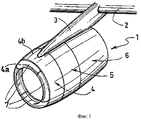
на фиг.1 представлено в аксонометрии схематическое изображение гондолы;figure 1 is a perspective view of a schematic illustration of a nacelle;
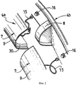
на фиг.2 в увеличенном масштабе изображен фрагмент кромки воздухозаборника, выполненной из секций согласно изобретению;figure 2 on an enlarged scale shows a fragment of the edge of the air intake made of sections according to the invention;
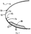
на фиг.3 представлен поперечный разрез секции согласно изобретению;figure 3 presents a cross section of a section according to the invention;
на фиг.4 в увеличенном масштабе представлена в разрезе секция согласно изобретению;figure 4 on an enlarged scale is a sectional view of a section according to the invention;
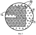
на фиг.5 представлен фрагмент нагревательного элемента в области звукопоглощающего устройства;figure 5 presents a fragment of a heating element in the area of a sound-absorbing device;
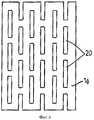
на фиг.6 схематически представлен один из вариантов исполнения части нагревательного элемента;6 schematically shows one embodiment of a portion of a heating element;
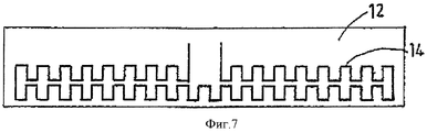
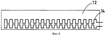
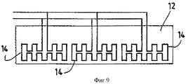
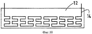
на фиг.7-10 представлены различные варианты исполнения электронагревательного элемента (элементов).7-10 presents various embodiments of the electric heating element (s).
Гондола 1 согласно изобретению, как показано на фиг.1, образует цилиндрическую полость для турбореактивного двигателя (не показан), обеспечивающую отвод создаваемых им воздушных потоков. Эта гондола 1 располагается под крылом 2, к которому она прикреплена посредством пилона 3. В ней также размещены различные узлы, необходимые для работы турбореактивного двигателя.The nacelle 1 according to the invention, as shown in FIG. 1, forms a cylindrical cavity for a turbojet engine (not shown), allowing the air flows created by it. This nacelle 1 is located under the wing 2, to which it is attached by means of a
В частности, гондола 1 содержит переднюю по потоку часть, образующую воздухозаборник 4, среднюю часть 5, вмещающую вентилятор (не показан) турбореактивного двигателя, и заднюю по потоку часть 6, вмещающую турбореактивный двигатель 2, в которой также находится система реверса тяги (не показана).In particular, the nacelle 1 comprises a downstream portion forming an air intake 4, a
Воздухозаборник 4 разделен на два элемента - кромку 4а, которая обеспечивает оптимальное всасывание в сторону турбореактивного двигателя воздуха, необходимого для питания его вентилятора и внутренних компрессоров, и задний по потоку элемент 4b, к которому крепится указанная кромка 4а и который обеспечивает надлежащий отвод воздуха в сторону лопастей вентилятора. Этот узел крепится по потоку перед кожухом вентилятора, являющегося составной частью средней части 5 гондолы.The air intake 4 is divided into two elements - an edge 4a, which provides optimal suction towards the turbojet engine of the air necessary to power its fan and internal compressors, and an
Кромка 4а воздухозаборника выполнена с помощью секций 7 согласно изобретению, прикрепленных по всему периметру гондолы 1 к заднему по потоку элементу 4b. Каждая секция 7 отделена от смежной секции посредством разделительного элемента 8, выполненного как одно целое с задним по потоку элементом 4b.The edge 4a of the air intake is made using sections 7 according to the invention, attached around the entire perimeter of the nacelle 1 to the
В данном конкретном примере кромка 4а воздухозаборника выполнена из четырех секций 7. Совершенно очевидно, что ее можно выполнить также из двух секций 7 в виде единой детали или же более чем из четырех секций 7.In this particular example, the edge of the air intake 4a is made of four sections 7. It is obvious that it can also be made of two sections 7 as a single part or more than four sections 7.
Каждая секция 7 содержит стенку 9, форма которой выбрана таким образом, чтобы придать кромке 4а нужный профиль, а также внутренний звукопоглощающий элемент 30 сотового типа, находящийся в контакте с обращенной к входу вентилятора зоной 10 стенки, содержащей множество отверстий 11, выполненных с равномерным шагом.Each section 7 contains a wall 9, the shape of which is selected in such a way as to give the edge 4a the desired profile, as well as an internal honeycomb sound-absorbing
Стенка 10 секции 7 имеет наружную обшивку 12, обращенную наружу кромки, внутреннюю обшивку 13, обращенную внутрь кромки, и электронагревательный элемент 14, установленный между внутренней обшивкой 13 и наружной обшивкой 12. Электронагревательный элемент 14 соединен с контактным выводом электропитания, который, в свою очередь, соединен с кабелем 15, вставляемым в разъем электропитания 16 на задней секции.The
Стенка 10 может быть оснащена электронагревательным элементом 14 лишь частично, в зависимости от того, какие зоны подлежат защите от обледенения. Так, на фиг.3 можно видеть, что стенка 10 оснащена электронагревательным элементом только в области звукопоглощающего элемента 30 на том участке стенки, который обращен к входу вентилятора. Следует обратить внимание, что электронагревательный элемент 14 не доходит до места крепления секции 7 к заднему по потоку элементу 4b и остается отделенным от средств соединения этих конструкций. Дело в том, что крепление секции 7 к заднему по потоку элементу 4b осуществляется, как правило, посредством заклепок (не показаны), которые не должны соприкасаться с электронагревательным элементом 14.The
Электронагревательный элемент 14 окружен защитным слоем типа смолы 17, который, в свою очередь, окружен слоями стекла 18, располагающимися по обе стороны от электронагревательного элемента 14.The
Наружная обшивка 12 обеспечивает наружный аэродинамический профиль кромки 4а. Она может быть выполнена из металла или какого-либо композитного материала, может быть предварительно отформованной или выполняться одновременно с установкой электронагревательного элемента 14. Толщина наружной обшивки 12 является относительно небольшой, что обеспечивает хорошую теплопередачу в направлении наружу кромки. Толщина кромки, например, может составлять несколько десятых долей миллиметра.The
Внутренняя обшивка 13 покрывает электронагревательный элемент 14 и завершает стенку 10. Как и наружная обшивка 12, она может быть выполнена из металла или композитного материала, может быть предварительно отформована или выполняться во время установки электронагревательного элемента 14. Следует иметь в виду, что внутренняя обшивка 13 и наружная обшивка 12 могут иметь разную толщину.The
Дополнительно можно добавить к внутренней обшивке 12 специальную отражающую полосу (не показана), которая будет располагаться между нагревательным элементом 14 и внутренней обшивкой 13, обеспечивая снижение потерь тепла со стороны внутренней обшивки 13 с целью концентрации рассеяния тепла в направлении наружной обшивки 12. Это позволит уменьшить потребление электроэнергии секцией 7 для обеспечения требуемой защиты от обледенения.Additionally, a special reflective strip (not shown) can be added to the
Различные слои, составляющие стенку 10 конструкции 7, соединяются друг с другом посредством специального связующего материала типа клея или смолы (не показан).The various layers constituting the
В качестве электронагревательного элемента 14 можно применить вырезной металлический резистор, резистивную органическую или металлическую ткань, а также резистивную органическую фольгу. Особенно предпочтительной формой этого элемента является форма змеевика. Разумеется, необходимо убедиться в том, что поверхность электронагревательного элемента 14 позволяет достичь требуемой противообледенительной температуры.As the
Выполнение электронагревательного элемента 14 в форме змеевика позволяет усилить связь между различными слоями. Эту связь можно дополнительно увеличить, выполнив в электронагревательном элементе 14 перфорацию или даже прорези 20 (см. фиг.6), позволяющие связующему материалу проникать в эту перфорацию, обеспечивая тем самым более тесное взаимодействие разных слоев. Надо иметь в виду, что если электронагревательный элемент 14 выполнен вместе с защитным слоем 17 из смолы, то этот узел должен содержать перфорацию 20.The implementation of the
Тот же принцип выполнения перфорации 20 для усиления сцепления между слоями может быть применен и для отражающей полосы.The same principle of
На фиг.4 иллюстрируется чередование различных слоев, составляющих стенку секции.Figure 4 illustrates the alternation of the various layers that make up the wall of the section.
В области внутреннего звукопоглощающего элемента 30 в стенке 10 выполнена перфорация по всей ее толщине. На фиг.5 подробно представлен находящийся в этой зоне электронагревательный элемент 14.In the region of the internal sound-absorbing
Следует отметить, что толщина стенки 10, перфорированной в области звукопоглощающего элемента 30, имеет большое значение для акустических свойств и поэтому не должна превышать некоторую предельную величину. Наличие нагревательного элемента 14 несколько повышает указанную толщину. Однако, поскольку звукопоглощающее устройство 30 расположено по направлению забора воздуха, стенка 10 в этом месте менее чувствительна к воздействиям. Таким образом, можно уменьшить в этой зоне толщину наружной обшивки 12, что позволит компенсировать указанное увеличение, обусловленное наличием нагревательного элемента 14.It should be noted that the thickness of the
Как уже говорилось выше, питание электронагревательного элемента 14 осуществляется от питающего контактного вывода, подключенного посредством кабеля 15 к источнику электропитания. Этот контактный вывод проходит через внутреннюю обшивку 13 секции 7 возле центра последней, а затем подключается к кабелю 15, который в свою очередь подключается к источнику электропитания заднего по потоку элемента 4b воздухозаборника 4. Следует принять меры, чтобы этот питающий контактный вывод был защищен в процессе изготовления стенки 10 и, в частности, в ходе полимеризации внутренней обшивки 13 и наружной обшивки 12, а также смол в случае использования органических обшивок из композитного материала.As already mentioned above, the power of the
На фиг.7-10 представлены различные возможные конфигурации электронагревательного элемента 14. Можно, в частности, отметить, что в устройстве по фиг.9 применено несколько включенных параллельно нагревательных элементов. В результате в случае отказа одного из этих элементов остальные смогут продолжать выполнение функции защиты от обледенения.Figures 7-10 show various possible configurations of the
Можно также предусмотреть использование нескольких слоев нагревательных электрических элементов 14, размещаемых при необходимости в соответствии с различными конфигурациями.You can also provide for the use of several layers of heating
Хотя выше изобретение было описано применительно к отдельным конкретным вариантам его осуществления, следует понимать, что оно никоим образом не ограничивается этими вариантами и охватывает самые разнообразные технические эквиваленты рассмотренных здесь средств, а также их различные комбинации, при условии, что они не выходят за пределы объема изобретения.Although the invention has been described above in relation to individual specific embodiments, it should be understood that it is in no way limited to these options and encompasses a wide variety of technical equivalents of the means discussed here, as well as their various combinations, provided that they do not go beyond the scope inventions.
Claims (12)
Applications Claiming Priority (2)
| Application Number | Priority Date | Filing Date | Title |
|---|---|---|---|
| FR0602547 | 2006-03-24 | ||
| FR0602547A FR2898868B1 (en) | 2006-03-24 | 2006-03-24 | STRUCTURE FOR AIR ENTRANCE LAUNCHER WITH ELECTRIC DEFROSTING |
Publications (2)
| Publication Number | Publication Date |
|---|---|
| RU2008141473A RU2008141473A (en) | 2010-04-27 |
| RU2422331C2 true RU2422331C2 (en) | 2011-06-27 |
Family
ID=37460908
Family Applications (1)
| Application Number | Title | Priority Date | Filing Date |
|---|---|---|---|
| RU2008141473/11A RU2422331C2 (en) | 2006-03-24 | 2007-03-08 | Section of gondola air intake edge with electric ice protection and acoustic absorption zone |
Country Status (8)
| Country | Link |
|---|---|
| US (1) | US8240982B2 (en) |
| EP (1) | EP1999020B1 (en) |
| CN (1) | CN101405184B (en) |
| CA (1) | CA2644592C (en) |
| ES (1) | ES2440955T3 (en) |
| FR (1) | FR2898868B1 (en) |
| RU (1) | RU2422331C2 (en) |
| WO (1) | WO2007110494A1 (en) |
Families Citing this family (22)
| Publication number | Priority date | Publication date | Assignee | Title |
|---|---|---|---|---|
| FR2930234B1 (en) * | 2008-04-21 | 2010-07-30 | Aircelle Sa | DEFROSTING AND / OR ANTI-FRICTION SYSTEM FOR AIRCRAFT BOAT ATTACK. |
| FR2934566B1 (en) * | 2008-08-04 | 2011-03-11 | Aircelle Sa | METHOD FOR MANUFACTURING A DEFROSTING ASSEMBLY ON A PANEL OF A NACELLE |
| FR2938237B1 (en) | 2008-11-13 | 2011-05-20 | Aircelle Sa | NACELLE FOR TURBOREACTOR WITH UPSTREATABLE TRANSLATABLE HOOD |
| FR2941439B1 (en) * | 2009-01-28 | 2011-01-14 | Aircelle Sa | ELECTRIC DEFROSTING DEVICE AND CONTROL SYSTEM THEREFOR |
| FR2943038B1 (en) * | 2009-03-13 | 2012-07-27 | Aircelle Sa | DEFROSTING DEVICE, IN PARTICULAR FOR AN AIRCRAFT NACELLE |
| FR2980458B1 (en) * | 2011-09-28 | 2013-08-30 | Aircelle Sa | LIP ASSEMBLY FOR ELECTRIC DEFROSTING TURBOREACTOR BOOM NACELLE |
| FR2980774B1 (en) * | 2011-10-03 | 2013-10-25 | Airbus Operations Sas | AIRCRAFT NACELLE COMPRISING A HOT AIR SUPPLY DEVICE OF A PANEL COMBINING ACOUSTIC AND FROZEN TREATMENTS |
| USD693068S1 (en) * | 2012-02-02 | 2013-11-05 | Foshan Shunde Xinshengyuan Electrical Applicances Co., Ltd. | Pet hair dryer |
| US8919494B2 (en) * | 2012-07-31 | 2014-12-30 | Rohr, Inc. | Electric heater for integration into an aircraft acoustic panel |
| US9488067B2 (en) * | 2014-01-14 | 2016-11-08 | The Boeing Company | Aircraft anti-icing systems having deflector vanes |
| US9656761B2 (en) | 2014-04-30 | 2017-05-23 | The Boeing Company | Lipskin for a nacelle and methods of making the same |
| US9604438B2 (en) | 2014-04-30 | 2017-03-28 | The Boeing Company | Methods and apparatus for noise attenuation in an engine nacelle |
| US9938852B2 (en) * | 2014-04-30 | 2018-04-10 | The Boeing Company | Noise attenuating lipskin assembly and methods of assembling the same |
| US9708072B2 (en) | 2014-04-30 | 2017-07-18 | The Boeing Company | Aircraft engine nacelle bulkheads and methods of assembling the same |
| US10368401B2 (en) | 2014-06-03 | 2019-07-30 | Aurora Flight Sciences Corporation | Multi-functional composite structures |
| US10167550B2 (en) | 2014-06-03 | 2019-01-01 | Aurora Flight Sciences Corporation | Multi-functional composite structures |
| US10285219B2 (en) | 2014-09-25 | 2019-05-07 | Aurora Flight Sciences Corporation | Electrical curing of composite structures |
| CN106081122A (en) * | 2016-06-01 | 2016-11-09 | 中国航空工业集团公司西安飞机设计研究所 | A kind of aircraft deicing device |
| FR3060650B1 (en) * | 2016-12-20 | 2019-05-31 | Airbus Operations | AIR INTAKE STRUCTURE FOR AN AIRCRAFT NACELLE |
| IT201700067602A1 (en) * | 2017-06-19 | 2018-12-19 | Leonardo Spa | AIR INTAKE FOR ENGINE GONDOLA FOR A AIRCRAFT AND ITS PROCEDURE FOR THE REALIZATION. |
| US10655539B2 (en) * | 2017-10-16 | 2020-05-19 | Rolls-Royce North America Technologies Inc. | Aircraft anti-icing system |
| FR3085303B1 (en) * | 2018-09-05 | 2020-11-20 | Airbus Operations Sas | SOUNDPROOFING PANEL WITH AN ALVEOLAR CORE AND AN DEFROSTING SYSTEM |
Family Cites Families (19)
| Publication number | Priority date | Publication date | Assignee | Title |
|---|---|---|---|---|
| GB885131A (en) * | 1958-04-24 | 1961-12-20 | Goodrich Co B F | Apparatus for and method of making a heating structure |
| FR1377304A (en) * | 1963-05-29 | 1964-11-06 | Pneumatiques, Caoutchouc Manufacture Et Plastiques Kleber-Colombes | Thermal defroster and its manufacturing process |
| GB1117843A (en) * | 1966-02-25 | 1968-06-26 | Rolls Royce | Improvements relating to anti-icing heating apparatus |
| US4688757A (en) | 1986-08-11 | 1987-08-25 | Dresser Industries, Inc. | Soft seat Y pattern globe valve |
| EP0459216A3 (en) * | 1990-06-01 | 1993-03-17 | The Bfgoodrich Company | Electrical heater de-icer |
| CA2176359C (en) * | 1993-11-30 | 2004-01-27 | David Charles Lawson | An electrically conductive composite heater and method of manufacture |
| FR2756254B1 (en) * | 1996-11-27 | 1999-01-29 | Eurocopter France | DEVICE FOR HEATING AN AERODYNAMIC PROFILE |
| FR2756253B1 (en) * | 1996-11-27 | 1999-01-29 | Eurocopter France | RESISTIVE ELEMENTS FOR HEATING AN AERODYNAMIC PROFILE, AND DEVICE FOR HEATING AN AERODYNAMIC PROFILE INCORPORATING SUCH ELEMENTS |
| US5934617A (en) * | 1997-09-22 | 1999-08-10 | Northcoast Technologies | De-ice and anti-ice system and method for aircraft surfaces |
| US6725645B1 (en) * | 2002-10-03 | 2004-04-27 | General Electric Company | Turbofan engine internal anti-ice device |
| US7588212B2 (en) * | 2003-07-08 | 2009-09-15 | Rohr Inc. | Method and apparatus for noise abatement and ice protection of an aircraft engine nacelle inlet lip |
| FR2866000B1 (en) * | 2004-02-11 | 2007-04-06 | Eurocopter France | HEATING MATERIAL COMPOSED OF ELECTRICALLY CONDUCTIVE FIBERS. |
| NL1025744C2 (en) * | 2004-03-16 | 2005-01-18 | Stork Fokker Aesp Bv | Laminate with metal layers, used for aerospace applications, contains electrical heating layer |
| WO2006136748A2 (en) * | 2005-06-22 | 2006-12-28 | Airbus France | Anti-icing and deicing system for aircraft engine pod with resistive mat |
| US7291815B2 (en) * | 2006-02-24 | 2007-11-06 | Goodrich Corporation | Composite ice protection heater and method of producing same |
| US7923668B2 (en) * | 2006-02-24 | 2011-04-12 | Rohr, Inc. | Acoustic nacelle inlet lip having composite construction and an integral electric ice protection heater disposed therein |
| FR2898869B1 (en) * | 2006-03-24 | 2008-12-12 | Aircelle Sa | ELECTRIC DEGIVER NACELLE AIR INLET LAUNDRY |
| FR2928625B1 (en) * | 2008-03-14 | 2012-11-30 | Aircelle Sa | ELECTRIC DEFROSTING DEVICE |
| FR2935357B1 (en) * | 2008-09-03 | 2010-08-27 | Aircelle Sa | METHOD FOR MANUFACTURING A NACELLE ELEMENT |
-
2006
- 2006-03-24 FR FR0602547A patent/FR2898868B1/en not_active Expired - Fee Related
-
2007
- 2007-03-08 CA CA2644592A patent/CA2644592C/en not_active Expired - Fee Related
- 2007-03-08 EP EP07731110.8A patent/EP1999020B1/en active Active
- 2007-03-08 ES ES07731110.8T patent/ES2440955T3/en active Active
- 2007-03-08 US US12/161,194 patent/US8240982B2/en active Active
- 2007-03-08 CN CN2007800103858A patent/CN101405184B/en not_active Expired - Fee Related
- 2007-03-08 WO PCT/FR2007/000413 patent/WO2007110494A1/en active Application Filing
- 2007-03-08 RU RU2008141473/11A patent/RU2422331C2/en not_active IP Right Cessation
Also Published As
| Publication number | Publication date |
|---|---|
| CN101405184B (en) | 2013-06-12 |
| US8240982B2 (en) | 2012-08-14 |
| EP1999020B1 (en) | 2013-10-09 |
| CN101405184A (en) | 2009-04-08 |
| WO2007110494A1 (en) | 2007-10-04 |
| RU2008141473A (en) | 2010-04-27 |
| FR2898868A1 (en) | 2007-09-28 |
| ES2440955T3 (en) | 2014-01-31 |
| CA2644592C (en) | 2015-01-06 |
| EP1999020A1 (en) | 2008-12-10 |
| CA2644592A1 (en) | 2007-10-04 |
| US20110120076A1 (en) | 2011-05-26 |
| FR2898868B1 (en) | 2008-12-12 |
Similar Documents
| Publication | Publication Date | Title |
|---|---|---|
| RU2422331C2 (en) | Section of gondola air intake edge with electric ice protection and acoustic absorption zone | |
| US8181900B2 (en) | Acoustic coating for an aircraft incorporating a frost treatment system by joule effect | |
| US8733688B2 (en) | Aircraft leading edge | |
| RU2471680C2 (en) | Coating for acoustic treatment including function for hot air processing of ice crust | |
| US5841079A (en) | Combined acoustic and anti-ice engine inlet liner | |
| US7963362B2 (en) | Acoustic panel having a variable acoustic characteristic | |
| US6557799B1 (en) | Acoustic treated thrust reverser bullnose fairing assembly | |
| US10486821B2 (en) | Jet engine anti-icing and noise-attenuating air inlets | |
| EP1495963B1 (en) | Method and apparatus for noise abatement and ice protection of an aircraft engine nacelle inlet lip | |
| US8584363B2 (en) | Method for making an acoustic panel for the air intake lip of a nacelle | |
| US7291815B2 (en) | Composite ice protection heater and method of producing same | |
| US4858721A (en) | Acoustic panel for sound insulating linings of gas ducts | |
| RU2492115C2 (en) | Turbojet nacelle air intake edge | |
| US20020139899A1 (en) | Process for de-icing by forced circulation of a fluid, an air intake cowling of a reaction motor and device for practicing the same | |
| US20100126798A1 (en) | Process for the production of an acoustically resistive structure, the acoustically resistive structure thus obtained, and coating using such a structure | |
| RU2500585C2 (en) | Turbojet nacelle air intake | |
| US20020139900A1 (en) | Process for de-icing an air intake cowling of a reaction motor and device for practicing the same | |
| US20110139927A1 (en) | Panel for an air intake of an aircraft nacelle that ensures optimized acoustic treatment and frost treatment | |
| US9630702B2 (en) | Noise attenuation for an open rotor aircraft propulsion system | |
| US20170283032A1 (en) | Aircraft including a wing with improved acoustic treatment | |
| US11643967B2 (en) | Nacelle air intake provided with a mixed ice protection system | |
| US20130040117A1 (en) | Wall reinforced composite material | |
| EP3418199B1 (en) | Air inlet for an aircraft engine nacelle and method of manufacturing such air inlet | |
| RU2521824C2 (en) | Assembly of elements connected by device protecting surface of one of said elements |
Legal Events
| Date | Code | Title | Description |
|---|---|---|---|
| MM4A | The patent is invalid due to non-payment of fees |
Effective date: 20160309 |