RU2500585C2 - Turbojet nacelle air intake - Google Patents
Turbojet nacelle air intake Download PDFInfo
- Publication number
- RU2500585C2 RU2500585C2 RU2011118077/11A RU2011118077A RU2500585C2 RU 2500585 C2 RU2500585 C2 RU 2500585C2 RU 2011118077/11 A RU2011118077/11 A RU 2011118077/11A RU 2011118077 A RU2011118077 A RU 2011118077A RU 2500585 C2 RU2500585 C2 RU 2500585C2
- Authority
- RU
- Russia
- Prior art keywords
- air intake
- panel
- edge
- additional segment
- wall
- Prior art date
Links
Images


Classifications
-
- F—MECHANICAL ENGINEERING; LIGHTING; HEATING; WEAPONS; BLASTING
- F02—COMBUSTION ENGINES; HOT-GAS OR COMBUSTION-PRODUCT ENGINE PLANTS
- F02K—JET-PROPULSION PLANTS
- F02K1/00—Plants characterised by the form or arrangement of the jet pipe or nozzle; Jet pipes or nozzles peculiar thereto
- F02K1/78—Other construction of jet pipes
- F02K1/82—Jet pipe walls, e.g. liners
- F02K1/822—Heat insulating structures or liners, cooling arrangements, e.g. post combustion liners; Infra-red radiation suppressors
-
- B—PERFORMING OPERATIONS; TRANSPORTING
- B64—AIRCRAFT; AVIATION; COSMONAUTICS
- B64D—EQUIPMENT FOR FITTING IN OR TO AIRCRAFT; FLIGHT SUITS; PARACHUTES; ARRANGEMENTS OR MOUNTING OF POWER PLANTS OR PROPULSION TRANSMISSIONS IN AIRCRAFT
- B64D29/00—Power-plant nacelles, fairings, or cowlings
- B64D29/06—Attaching of nacelles, fairings or cowlings
-
- B—PERFORMING OPERATIONS; TRANSPORTING
- B64—AIRCRAFT; AVIATION; COSMONAUTICS
- B64D—EQUIPMENT FOR FITTING IN OR TO AIRCRAFT; FLIGHT SUITS; PARACHUTES; ARRANGEMENTS OR MOUNTING OF POWER PLANTS OR PROPULSION TRANSMISSIONS IN AIRCRAFT
- B64D33/00—Arrangements in aircraft of power plant parts or auxiliaries not otherwise provided for
- B64D33/02—Arrangements in aircraft of power plant parts or auxiliaries not otherwise provided for of combustion air intakes
-
- F—MECHANICAL ENGINEERING; LIGHTING; HEATING; WEAPONS; BLASTING
- F02—COMBUSTION ENGINES; HOT-GAS OR COMBUSTION-PRODUCT ENGINE PLANTS
- F02C—GAS-TURBINE PLANTS; AIR INTAKES FOR JET-PROPULSION PLANTS; CONTROLLING FUEL SUPPLY IN AIR-BREATHING JET-PROPULSION PLANTS
- F02C7/00—Features, components parts, details or accessories, not provided for in, or of interest apart form groups F02C1/00 - F02C6/00; Air intakes for jet-propulsion plants
- F02C7/04—Air intakes for gas-turbine plants or jet-propulsion plants
-
- B—PERFORMING OPERATIONS; TRANSPORTING
- B64—AIRCRAFT; AVIATION; COSMONAUTICS
- B64D—EQUIPMENT FOR FITTING IN OR TO AIRCRAFT; FLIGHT SUITS; PARACHUTES; ARRANGEMENTS OR MOUNTING OF POWER PLANTS OR PROPULSION TRANSMISSIONS IN AIRCRAFT
- B64D33/00—Arrangements in aircraft of power plant parts or auxiliaries not otherwise provided for
- B64D33/02—Arrangements in aircraft of power plant parts or auxiliaries not otherwise provided for of combustion air intakes
- B64D2033/0206—Arrangements in aircraft of power plant parts or auxiliaries not otherwise provided for of combustion air intakes comprising noise reduction means, e.g. acoustic liners
-
- B—PERFORMING OPERATIONS; TRANSPORTING
- B64—AIRCRAFT; AVIATION; COSMONAUTICS
- B64D—EQUIPMENT FOR FITTING IN OR TO AIRCRAFT; FLIGHT SUITS; PARACHUTES; ARRANGEMENTS OR MOUNTING OF POWER PLANTS OR PROPULSION TRANSMISSIONS IN AIRCRAFT
- B64D33/00—Arrangements in aircraft of power plant parts or auxiliaries not otherwise provided for
- B64D33/02—Arrangements in aircraft of power plant parts or auxiliaries not otherwise provided for of combustion air intakes
- B64D2033/0266—Arrangements in aircraft of power plant parts or auxiliaries not otherwise provided for of combustion air intakes specially adapted for particular type of power plants
- B64D2033/0286—Arrangements in aircraft of power plant parts or auxiliaries not otherwise provided for of combustion air intakes specially adapted for particular type of power plants for turbofan engines
-
- Y—GENERAL TAGGING OF NEW TECHNOLOGICAL DEVELOPMENTS; GENERAL TAGGING OF CROSS-SECTIONAL TECHNOLOGIES SPANNING OVER SEVERAL SECTIONS OF THE IPC; TECHNICAL SUBJECTS COVERED BY FORMER USPC CROSS-REFERENCE ART COLLECTIONS [XRACs] AND DIGESTS
- Y02—TECHNOLOGIES OR APPLICATIONS FOR MITIGATION OR ADAPTATION AGAINST CLIMATE CHANGE
- Y02T—CLIMATE CHANGE MITIGATION TECHNOLOGIES RELATED TO TRANSPORTATION
- Y02T50/00—Aeronautics or air transport
- Y02T50/60—Efficient propulsion technologies, e.g. for aircraft
Abstract
Description
Изобретение относится к гондоле турбореактивного двигателя.The invention relates to a nacelle of a turbojet engine.
Если говорить в общих чертах, гондола летательного аппарата включает в себя воздухозаборник, среднюю секцию и нижнюю по потоку секцию. Используемый в данной заявке термин «нижний по потоку» относится к направлению, соответствующему направлению потока холодного воздуха, поступающего в турбореактивный двигатель. По аналогии, термин «верхний по потоку» относится к противоположному направлению.Generally speaking, an aircraft nacelle includes an air intake, a middle section and a downstream section. Used in this application, the term "downstream" refers to the direction corresponding to the direction of flow of cold air entering the turbojet engine. By analogy, the term “upstream” refers to the opposite direction.
Воздухозаборник находится выше по потоку от турбореактивного двигателя, назначение которого состоит в приведении летательного аппарата в движение. Ниже по потоку от воздухозаборника расположена средняя секция, охватывающая собой вентилятор турбореактивного двигателя. Еще ниже по потоку располагается нижняя по потоку секция, в которой, как правило, находятся средства реверса тяги, охватывающие камеру сгорания турбореактивного двигателя. Гондола оканчивается соплом, выпускное отверстие которого находится ниже по потоку от турбореактивного двигателя.The air intake is located upstream of the turbojet engine, the purpose of which is to bring the aircraft into motion. Downstream of the air intake is the middle section, which encloses a fan of a turbojet engine. Still lower downstream is the downstream section, in which, as a rule, there are thrust reversers covering the combustion chamber of a turbojet engine. The nacelle ends with a nozzle, the outlet of which is located downstream of the turbojet engine.
Воздухозаборник содержит по меньшей мере одну внешнюю панель, по меньшей мере одну внутреннюю панель и воздухозаборную кромку, которая имеет внутреннюю стенку, вводимую в контакт с воздушным потоком, поступающим в турбореактивный двигатель. Внешние панели (внешняя панель) обычно представляют собой цельное продолжение воздухозаборной кромки. Говоря другими словами, обычные внешние панели (внешнюю панель) нельзя рассматривать как размещенные на воздухозаборной кромке в результате установки.The air intake comprises at least one outer panel, at least one inner panel and an air intake edge that has an inner wall that is brought into contact with the air stream entering the turbojet engine. External panels (external panel) are usually a one-piece continuation of the air intake edge. In other words, ordinary external panels (external panel) cannot be considered as placed on the air intake edge as a result of installation.
Что касается внутренних панелей (внутренней панели), то воздухозаборная кромка крепится к ним съемным образом. Следовательно, подвижная структура, включающая в себя воздухозаборную кромку и внешние панели (внешнюю панель), может совершать перемещение относительно неподвижной структуры, включающей в себя внутренние панели (внутреннюю панель). Такая подвижная структура позволяет получать доступ к оборудованию, помещенному внутри гондолы, в случае проведения работ по его техобслуживанию.As for the inner panels (inner panel), the air intake edge is attached to them in a removable manner. Therefore, the movable structure including the air intake edge and the outer panels (outer panel) can move relative to the fixed structure including the inner panels (inner panel). Such a movable structure allows access to equipment placed inside the nacelle in the event of maintenance work.
Кроме того, внутренние панели (внутренняя панель) могут быть снабжены по меньшей мере одной акустической панелью, в частности, сотового типа, способной поглощать акустические помехи, создаваемые работающим турбореактивным двигателем.In addition, the inner panels (inner panel) may be provided with at least one acoustic panel, in particular a honeycomb type, capable of absorbing acoustic noise caused by a working turbojet engine.
Гондола также содержит перегородку, которая обычно закреплена на воздухозаборной кромке и ограничивает собою полость, в которой размещены кабели или различные средства, обеспечивающие функционирование гондолы, в частности, средства удаления льда с воздухозаборной кромки.The nacelle also contains a partition, which is usually fixed to the air intake edge and defines a cavity in which cables or various means are provided for the nacelle to function, in particular ice removal means from the air intake edge.
Средняя секция охватывает вентилятор турбореактивного двигателя. Эта секция прикреплена к воздухозаборнику неподвижным образом с помощью внутренних панелей (внутренней панели) или подвижным - с помощью внешних панелей (внешней панели), при этом она обеспечивает непрерывность аэродинамического обтекания.The middle section covers the turbojet fan. This section is fixed to the air intake in a fixed manner with the help of internal panels (internal panel) or movable - with the help of external panels (external panel), while it provides continuous aerodynamic flow.
Для проведения операций по техобслуживанию оборудования, размещенного внутри воздухозаборника, указанную подвижную структуру смещают вверх по потоку относительно средней секции при помощи направляющих средств. Такие направляющие средства представлены, как правило, системой рельсов.To carry out maintenance operations on equipment located inside the air intake, said movable structure is displaced upstream of the middle section using guide means. Such guiding means are usually represented by a rail system.
Таким образом, при открытом положении, т.е. когда воздухозаборная кромка и внешние панели (внешняя панель) сдвинуты вверх по потоку, оператор получает доступ внутрь гондолы и может приступать к выполнению требуемых работ по техобслуживанию.Thus, in the open position, i.e. when the air intake edge and the outer panels (outer panel) are shifted upstream, the operator gains access to the inside of the nacelle and can begin to perform the required maintenance work.
Однако в условиях полета воздухозаборник находится в закрытом положении, при котором указанная подвижная структура скреплена с внутренними панелями (внутренней панели) и со средней секцией.However, in flight conditions, the air intake is in the closed position, in which said movable structure is bonded to the inner panels (inner panel) and to the middle section.
Зона сопряжения подвижной и неподвижной структур гондолы обычно находится вблизи вышеупомянутой перегородки. В этой связи воздухозаборная кромка снабжена расположенным вблизи перегородки средством сопряжения, которое, как правило, представлено нижним по потоку Г-образным концом, выполненным с возможностью скрепления с ответным средством, находящимся напротив него и принадлежащим к внутренней панели.The interface between the movable and fixed structures of the nacelle is usually located near the aforementioned partition. In this regard, the air intake edge is provided with interface means located near the partition, which, as a rule, is represented by a downstream L-shaped end that can be fastened with a response means located opposite it and belonging to the inner panel.
Однако на предполетной стадии, т.е. когда турбореактивный двигатель находится на фазе ускорения при еще неподвижном самолете, воздухозаборная кромка подвергается действию высоких температур, достигающих 400°C. При таких тепловых нагрузках возникает значительное расширение материалов, из которых изготовлена воздухозаборная кромка. Это расширение приводит к существенному деформированию кромки, при котором создаются усилия, вытягивающие подвижную структуру вверх по потоку. В результате, в зоне сопряжения возникает большой зазор, разительно ухудшающий эксплуатационные характеристики турбореактивного двигателя.However, at the preflight stage, i.e. when the turbojet engine is in the acceleration phase while the aircraft is still stationary, the intake edge is exposed to high temperatures reaching 400 ° C. With such thermal loads, there is a significant expansion of the materials of which the air intake lip is made. This expansion leads to a significant deformation of the edge, which creates forces that pull the movable structure upstream. As a result, a large gap arises in the interface zone, dramatically worsening the operational characteristics of the turbojet engine.
Более того, поскольку внутренние панели (внутренняя панель) изготовлены, как правило, из композитных материалов, они подвергаются действию значительных тепловых нагрузок, ведущих к разрушению конструкции.Moreover, since the inner panels (inner panel) are made, as a rule, of composite materials, they are exposed to significant thermal loads, leading to the destruction of the structure.
Соответственно основная задача изобретения заключается в разработке воздухозаборника для гондолы, лишенного указанных выше недостатков.Accordingly, the main objective of the invention is to develop an air intake for the nacelle, devoid of the above disadvantages.
В соответствии с первым аспектом изобретения, поставленная задача решена путем создания воздухозаборника для гондолы турбореактивного двигателя, обеспечивающего направленное пропускание воздушного потока к вентилятору турбореактивного двигателя и содержащего по меньшей мере одну внешнюю панель, по меньшей мере одну внутреннюю панель и воздухозаборную кромку, которая снабжена внутренней стенкой, вводимой в контакт с воздушным потоком, поступающим в турбореактивный двигатель, а также перегородку, отделяющую воздухозаборную кромку от остальной части гондолы. Предложенный воздухозаборник характеризуется тем, что воздухозаборная кромка снабжена добавочным сегментом, выполненным с возможностью прикрепления к внутренней панели и проходящим по существу по линии продолжения внутренней стенки в сторону нижней по потоку части воздухозаборника на длину, примерно равную по меньшей мере максимальному расстоянию между перегородкой и воздухозаборной кромкой.In accordance with the first aspect of the invention, the problem is solved by creating an air intake for a nacelle of a turbojet engine, providing directed transmission of air flow to the fan of the turbojet engine and containing at least one outer panel, at least one inner panel and an air intake edge that is provided with an inner wall brought into contact with the air flow entering the turbojet engine, as well as the partition separating the air intake edge o t of the rest of the gondola. The proposed air intake is characterized in that the air intake edge is provided with an additional segment adapted to be attached to the inner panel and extending substantially along the line of extension of the internal wall towards the downstream part of the air intake by a length approximately equal to at least the maximum distance between the partition and the air intake edge .
Таким образом, предложенный воздухозаборник содержит воздухозаборную кромку, внутренняя стенка которой снабжена добавочным сегментом, проходящим за пределы перегородки в сторону нижней по потоку части воздухозаборника. Это значит, что зона сопряжения, обеспечиваемая этим добавочным сегментом, смещена вниз по потоку на большее расстояние по сравнению с зоной сопряжения, присущей системам известного уровня техники. Благодаря этой особенности, указанная зона сопряжения больше не подвергается тепловым нагрузкам или подвергается им лишь в очень незначительной степени, и, следовательно, деформация воздухозаборной кромки уже не происходит, что исключает вероятность возникновения зазора в указанной зоне.Thus, the proposed air intake comprises an air intake edge, the inner wall of which is provided with an additional segment extending beyond the partition towards the downstream part of the air intake. This means that the mating zone provided by this additional segment is shifted downstream by a greater distance compared to the mating zone inherent in prior art systems. Due to this feature, the specified mating zone is no longer subjected to thermal stresses or is exposed to them only to a very small extent, and, therefore, deformation of the intake edge does not occur anymore, which eliminates the possibility of a gap in the specified zone.
При этом не затрудняется доступ к находящемуся внутри гондолы оборудованию, равно как и к внутренним панелям (внутренней панели), в частности, к акустическому экрану.At the same time, access to the equipment inside the gondola, as well as to the internal panels (internal panel), in particular, to the acoustic screen, is not impeded.
В соответствии с другими вариантами изобретения, предложенный воздухозаборник характеризуется перечисленными ниже одним или несколькими необязательными признаками, которые можно рассматривать как по отдельности, так и в разнообразных комбинациях:In accordance with other variants of the invention, the proposed air intake is characterized by the following one or more optional features that can be considered both individually and in various combinations:
- добавочный сегмент содержит элемент сопряжения, выполненный с возможностью прикрепления к ответному элементу сопряжения, установленному на внутренней панели; в результате, становится возможным прикреплять воздухозаборную кромку к внутренней панели съемным образом;- the additional segment contains a mating element configured to attach to the mating response element mounted on the inner panel; as a result, it becomes possible to attach the air intake edge to the inner panel in a removable manner;
- добавочный сегмент установлен на внутренней стенке воздухозаборной кромки; в результате, при реализации изобретения становится возможным использовать обычные воздухозаборные кромки;- the additional segment is installed on the inner wall of the intake edge; as a result, when implementing the invention, it becomes possible to use conventional air intake edges;
- добавочный сегмент представляет собой конструктивную панель с ячеистой сердцевиной, что позволяет повысить механическую прочность этого сегмента;- the additional segment is a structural panel with a cellular core, which allows to increase the mechanical strength of this segment;
- указанная конструктивная панель является акустической, что позволяет увеличить акустическую поверхность и, тем самым, улучшить акустические свойства гондолы;- the specified structural panel is acoustic, which allows to increase the acoustic surface and, thereby, improve the acoustic properties of the nacelle;
- добавочный сегмент представляет собой по существу непрерывное продолжение внутренней стенки воздухозаборной кромки, что облегчает сборку воздухозаборника;- the additional segment is a substantially continuous extension of the inner wall of the air intake edge, which facilitates the assembly of the air intake;
- внутренняя стенка и добавочный сегмент представляют собой конструктивные панели с ячеистыми сердцевинами, что позволяет увеличить акустическую поверхность воздухозаборника;- the inner wall and the additional segment are structural panels with honeycomb cores, which allows to increase the acoustic surface of the air intake;
- на добавочном сегменте в зоне сопряжения с внутренней панелью установлена усиливающая перегородка, которая повышает конструктивную прочность подвижной структуры, но не приводит к существенному возрастанию ее массы.- a reinforcing partition is installed on the additional segment in the interface zone with the inner panel, which increases the structural strength of the movable structure, but does not lead to a significant increase in its mass.
В соответствии с другим аспектом изобретения, предложена гондола для турбореактивного двигателя, снабженная указанным воздухозаборником.In accordance with another aspect of the invention, there is provided a nacelle for a turbojet engine equipped with said air intake.
Далее изобретение описано более подробно со ссылкой на приложенные чертежи, причем приведенное описание не следует рассматривать как ограничение объема патентных притязаний данного изобретения. На указанных чертежах:The invention is further described in more detail with reference to the attached drawings, and the description should not be construed as limiting the scope of patent claims of this invention. In the indicated drawings:
фиг.1 в аксонометрии изображает гондолу, снабженную предложенным воздухозаборником, который показан в своем раскрытом положении;figure 1 in a perspective view depicts a nacelle equipped with the proposed air intake, which is shown in its open position;
фиг.2 в продольном сечении изображает фрагмент предложенного воздухозаборника, который показан в своем закрытом положении;figure 2 in longitudinal section shows a fragment of the proposed air intake, which is shown in its closed position;
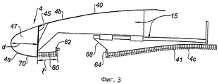
фиг.3 в продольном сечении изображает фрагмент показанного на фиг.2 воздухозаборника, находящегося в раскрытом положении;figure 3 in longitudinal section depicts a fragment shown in figure 2 of the inlet in the open position;
фиг.4 в продольном сечении изображает альтернативный вариант показанного на фиг.2 воздухозаборника, находящегося в закрытом положении;figure 4 in longitudinal section depicts an alternative embodiment shown in figure 2 of the inlet in the closed position;
фиг.5 в продольном сечении изображает другой альтернативный вариант показанного на фиг.2 воздухозаборника, который показан в своем раскрытом положении;5 is a longitudinal sectional view showing another alternative embodiment of the air intake shown in FIG. 2, which is shown in its open position;
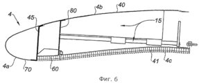
фиг.6 в продольном сечении изображает еще один альтернативный вариант показанного на фиг.2 воздухозаборника, находящегося в закрытом положении.FIG. 6 is a longitudinal sectional view showing another alternative embodiment of the inlet shown in FIG. 2 in a closed position.
Как следует из фиг.1, гондола 1, снабженная предложенным воздухозаборником, образует трубчатый корпус турбореактивного двигателя (не показан), обеспечивающий направленное пропускание создаваемых им воздушных потоков с образованием внутренних и внешних линий обтекания, необходимых для достижения оптимальных эксплуатационных показателей. Внутри гондолы находятся различные компоненты, необходимые для работы турбореактивного двигателя, а также некоторые вспомогательные системы, например, система реверса тяги.As follows from figure 1, the nacelle 1, equipped with the proposed air intake, forms a tubular housing of a turbojet engine (not shown), providing directional transmission of the air flows created by it with the formation of internal and external flow lines necessary to achieve optimal performance. Inside the nacelle are various components necessary for the operation of a turbojet engine, as well as some auxiliary systems, for example, a thrust reversal system.
Гондола 1 пилоном 3 прикреплена к какой-либо неподвижной структуре летательного аппарата, например к крылу 2.Gondola 1
Если говорить более подробно, гондола 1 включает в себя предложенный воздухозаборник 4, расположенный в верхней по потоку части, среднюю секцию 5, охватывающую вентилятор (не показан) турбореактивного двигателя, и нижнюю по потоку секцию 6, которая охватывает турбореактивный двигатель и в которой обычно размещена система реверса тяги (не показана).In more detail, the nacelle 1 includes the proposed
В состав средней секции 5 входит кожух 9, прикрепленный одним из своих концов к воздухозаборнику 4 с обеспечением непрерывности линий обтекания.The composition of the
Воздухозаборник 4 разделен на три зоны. Первая зона, находящаяся выше всего по потоку, представляет собой воздухозаборную кромку 4a, обеспечивающую оптимальный забор воздуха, нагнетаемого в направлении турбореактивного двигателя для его подвода к вентилятору и внутренним компрессорам турбореактивного двигателя. Вторая зона - это секция 4b, присоединенная к одному из концов воздухозаборной кромки 4a и включающая по меньшей мере одну внешнюю панель 40. Третья зона - секция 4c, присоединенная к другому концу воздухозаборной кромки 4a и включающая по меньшей мере одну внутреннюю панель 41.The
Внутренние панели (внутренняя панель) 41 обеспечивают надлежащее проведение воздуха к лопастям (не показаны) вентилятора. Поэтому эти панели (панель) 41 прикреплены своим нижним по потоку концом с помощью крепежных скоб к верхнему по потоку концу кожуха 9. В результате, внутренние панели (внутренняя панель) 41 образуют вместе со средней секцией 5 структуру, которая является неподвижной относительно гондолы 1. Кроме того, эти панели (панель) могут включать в себя акустический экран, служащий для ослабления шума, обусловленного работой турбореактивного двигателя и вибрациями указанной структуры. Такой акустический экран образован, как правило, сотовой или любой иной известной структурой, способной поглощать шум.The inner panels (inner panel) 41 ensure proper air flow to the fan blades (not shown). Therefore, these panels (panel) 41 are attached with their downstream end using fastening brackets to the upstream end of the
Внутренние панели (внутреннюю панель) 41 обычно изготавливают из композитного материала, содержащего углерод, или даже из алюминия.The inner panels (inner panel) 41 are usually made of a composite material containing carbon, or even aluminum.
Согласно изобретению, воздухозаборная кромка 4a прикреплена к внешним панелям (внешней панели) 40 с образованием единого отсоединяемого элемента, называемого подвижной структурой. В этой связи воздухозаборная кромка 4a может быть выполнена за одно целое с внешними панелями (внешней панелью) 40.According to the invention, the
Внешние панели (внешнюю панель) 40 изготавливают, как правило, из композитного материала, содержащего углерод, или даже из алюминия.The outer panels (outer panel) 40 are made, as a rule, of a composite material containing carbon, or even aluminum.
Воздухозаборную кромку 4а выполняют, как правило, из алюминия, титана или любого другого известного высокотемпературного композитного материала.The
Чтобы обеспечить возможность отвода подвижной структуры вверх по потоку от гондолы 1, гондолу обычно снабжают направляющими средствами 15, обеспечивающими по существу прямолинейное перемещение внешних панелей (внешней панели) 40 в направлении вверх по потоку от гондолы 1, с тем чтобы можно было раскрыть воздухозаборник 4 для проведения техобслуживания. В качестве примера системы рельсов можно назвать системы, описанные в заявке FR 2906568, например, рельсовые каретки; расположенный в желобе рельс, взаимодействующий с направляющей системой; систему роликовых салазок, взаимодействующих с соответствующим рельсом; а также продольный валик, совершающий скользящее перемещение через соответствующее отверстие.In order to allow the movable structure to be taken upstream from the nacelle 1, the nacelle is usually provided with guiding means 15 that provide substantially rectilinear movement of the outer panels (outer panel) 40 in an upstream direction from the nacelle 1 so that the
Предложенный воздухозаборник 4 содержит также перегородку 45, отделяющую воздухозаборную кромку 4a от остальной части воздухозаборника. Эта перегородка ограничивает полость 47, в которой размещается различное оборудование, способствующее надлежащему функционированию гондолы 1, например, противообледенительные устройства.The proposed
Если рассмотреть предложенный воздухозаборник 4 в продольном сечении, то можно видеть, что максимальное расстояние между перегородкой 45 и воздухозаборной кромкой 4a - это расстояние, обозначенное как d. В данном случае максимальное расстояние d соответствует расстоянию между перегородкой 45 и наиболее удаленной от нее в продольном сечении точкой воздухозаборной кромки 4a. Данное расстояние d равно, как правило, протяженности полости 47.If we consider the proposed
Перегородка 45 изготовлена, как правило, из алюминия, титана или любого другого известного высокотемпературного композитного материала.The
Воздухозаборная кромка 4a содержит также добавочный сегмент 60, выполненный с возможностью прикрепления к внутренней панели 41 и проходящий за пределы перегородки 45, по существу по линии продолжения внутренней стенки 70, на длину l, примерно равную по меньшей мере указанному максимальному расстоянию d между перегородкой 45 и воздухозаборной кромкой 4a.The
Поскольку добавочный сегмент 60 проходит в направлении нижней по потоку части предложенного воздухозаборника, а в более общем смысле, гондолы 1, зона сопряжения между внутренними панелями 41 и добавочным сегментом 60 уже не испытывает действие деформации воздухозаборной кромки 4a, или испытывает его лишь в очень незначительной степени. Соответственно, в указанной зоне уже не возникает зазор между внутренней панелью 41 и добавочным сегментом 60, или этот зазор очень незначителен. Благодаря отсутствию такого зазора возрастает срок службы воздухозаборника 4 по сравнению с воздухозаборниками известного уровня техники и снижается вероятность разрыва зоны крепления в условиях полета летательного аппарата. Кроме того, благодаря сохранению непрерывности линий обтекания, не нарушаются аэродинамические характеристики.Since the
Следует также отметить, что в такой системе уже не может возникнуть зазор в указанной зоне сопряжения, обусловленный тепловой деформацией воздухозаборной кромки 4a, что позволяет сохранить надежное крепление в условиях полета летательного аппарата.It should also be noted that in such a system there can no longer be a gap in the indicated interface zone due to thermal deformation of the
Длина l добавочного сегмента 60 лежит обычно в пределах от 50 до 400 мм, в частности от 150 до 300 мм, например, равна 200 мм. При такой длине добавочный сегмент 60 обеспечивает зону сопряжения, не подверженную действию деформаций воздухозаборной кромки 4а или подверженную им лишь в незначительной степени.The length l of the
Добавочный сегмент 60 выполняют обычно из алюминия или углеродного композитного материала.The
В соответствии с предпочтительным вариантом изобретения, представленным на фиг.2 и 3, добавочный сегмент 60 установлен на внутренней стенке 70 воздухозаборной кромки 4a. Данное обстоятельство позволяет применять настоящее изобретение в отношении обычных известных воздухозаборных кромок. Установку добавочного сегмента 60 можно осуществить, например, при помощи соединительных накладок или любых иных известных средств.In accordance with the preferred embodiment of the invention shown in FIGS. 2 and 3, an
В данном случае в качестве добавочного сегмента 60 целесообразно использовать конструктивную панель с ячеистой сердцевиной, что позволит в еще большей степени повысить механическую прочность этого добавочного сегмента 60.In this case, it is advisable to use a structural panel with a honeycomb core as an
Согласно предпочтительному варианту изобретения, указанная конструктивная панель представляет собой акустическую панель, что позволяет увеличить площадь акустической поверхности и, тем самым, улучшить акустические характеристики гондолы 1.According to a preferred embodiment of the invention, said structural panel is an acoustic panel, which allows to increase the acoustic surface area and, thereby, improve the acoustic characteristics of the nacelle 1.
Чтобы повысить эффективность поглощения шума, акустическую обработку внутренней панели 41 и добавочного сегмента 60 можно выполнять по-разному. В частности, для получения разных величин акустического сопротивления, можно изменить некоторые параметры акустической панели, например, глубину акустических ячеек, количество акустических слоев, диаметр акустических отверстий. Можно также предусмотреть переходную зону между двумя участками акустической обработки.In order to increase the noise absorption efficiency, the acoustic processing of the
В соответствии с одним из предпочтительных вариантов изобретения, добавочный сегмент 60 снабжен элементом 62 сопряжения, выполненным с возможностью скрепления с ответным элементом 64 сопряжения, установленным на внутренней панели 41. В результате такого решения становится возможным прикреплять воздухозаборную кромку 4а к внутренней панели 41 разъемным образом. Элемент 64 сопряжения находится по существу напротив элемента 62 сопряжения, при этом он имеет форму, являющуюся по существу комплементарной форме указанного элемента 62.According to one preferred embodiment of the invention, the
В качестве элементов 62 и 64 сопряжения можно использовать любые сопрягаемые элементы, известные из уровня техники. При этом элементы 62 и 64 сопряжения могут также выполнять функцию центрирования подвижной структуры относительно неподвижной структуры. В качестве таких средств можно назвать жесткие центрирующие средства типа центрирующих штырей, взаимодействующих с соответствующими отверстиями, и/или гибкие средства типа упругих лапок, обеспечивающие конструктивную непрерывность. В случае использования упругой лапки, ее помещают на линии продолжения добавочного сегмента 60. В качестве примера подобных упругих лапок можно привести лапки, описанные в международной заявке WO 2008/040877.As
В качестве примера средств центрирования добавочного сегмента 60 и внутренней панели 41 можно назвать средства, описанные в заявке FR 2906568.As an example of the centering means of the
Элемент 62 сопряжения может быть закреплен на нижнем по потоку конце поверхности добавочного сегмента 60 и ориентирован внутрь предложенного воздухозаборника 4. В альтернативном случае этот элемент 62 сопряжения образует продолжение нижнего по потоку конца добавочного сегмента 60.The
Конструкция направляющих средств 15 может выступать вверх по потоку за пределы зоны сопряжения внутренней панели 41. Если требуется зафиксировать конец указанной конструкции, выходящий за пределы внутренней панели 41, то можно предусмотреть стяжку 68, закрепляемую на элементе 64 сопряжения внутренней панели или на неакустической обшивке указанной панели 41 и направленную внутрь воздухозаборника 4. В качестве стяжки 68 можно использовать любое известное средство, пригодное для конкретной ситуации, в частности, крепежную скобу.The design of the guide means 15 may protrude upstream beyond the mating zone of the
В соответствии с предпочтительным вариантом изобретения, представленным на сриг.4, добавочный сегмент 60 является непрерывным продолжением внутренней стенки 70. Такое техническое решение упрощает сборку предложенного воздухозаборника 4. В случае, когда внутренняя стенка 70 представляет собой металлический лист, покрытый внешней обшивкой, добавочный сегмент 60 тоже можно выполнить в виде листа, покрытого внешней обшивкой. В соответствии с вариантом изобретения, представленным на фиг.5, внутренняя стенка 70 и добавочный сегмент 60 представляют собой конструктивные панели с ячеистой сердцевиной, подвергнутые при необходимости акустической обработке. Как указано выше, добавочный сегмент 60 и внутренняя стенка 70 могут иметь акустическую обработку, отличную от обработки внутренней панели 41. Подобным же образом, по-разному можно выполнить и акустическую обработку внутренней стенки 70 и добавочного сегмента 60, придав им разные значения акустических сопротивлений. В результате удается изменить некоторые параметры акустической панели, например, глубину акустических ячеек, количество ячеистых слоев, диаметр акустических отверстий.According to the preferred embodiment of the invention shown in Fig. 4, the
В соответствии с вариантом изобретения, представленным на фиг.6, на добавочном сегменте 60 в зоне сопряжения с внутренней панелью 41 установлена усиливающая перегородка 80, которая повышает конструктивную прочность подвижной структуры, но не приводит к существенному возрастанию ее массы. Усиливающую перегородку 80 крепят обычно ниже по потоку от обычной перегородки 45 и напротив нее. В качестве примера материала для усиливающей перегородки 80 можно назвать углеродный акустический материал, при использовании которого масса гондолы 1 существенно не изменяется.In accordance with the embodiment of the invention shown in FIG. 6, a reinforcing
Claims (9)
Applications Claiming Priority (3)
| Application Number | Priority Date | Filing Date | Title |
|---|---|---|---|
| FR0805553A FR2936777B1 (en) | 2008-10-08 | 2008-10-08 | AIR INTAKE STRUCTURE FOR A NACELLE FOR TURBOJET ENGINE |
| FR08/05553 | 2008-10-08 | ||
| PCT/FR2009/000893 WO2010040907A1 (en) | 2008-10-08 | 2009-07-21 | Air intake structure for a turbine engine nacelle |
Publications (2)
| Publication Number | Publication Date |
|---|---|
| RU2011118077A RU2011118077A (en) | 2012-11-20 |
| RU2500585C2 true RU2500585C2 (en) | 2013-12-10 |
Family
ID=40673956
Family Applications (1)
| Application Number | Title | Priority Date | Filing Date |
|---|---|---|---|
| RU2011118077/11A RU2500585C2 (en) | 2008-10-08 | 2009-07-21 | Turbojet nacelle air intake |
Country Status (8)
| Country | Link |
|---|---|
| US (1) | US20110192134A1 (en) |
| EP (1) | EP2344383A1 (en) |
| CN (1) | CN102171101A (en) |
| BR (1) | BRPI0917880A2 (en) |
| CA (1) | CA2733602A1 (en) |
| FR (1) | FR2936777B1 (en) |
| RU (1) | RU2500585C2 (en) |
| WO (1) | WO2010040907A1 (en) |
Cited By (1)
| Publication number | Priority date | Publication date | Assignee | Title |
|---|---|---|---|---|
| RU2806229C2 (en) * | 2019-04-26 | 2023-10-30 | Сафран Насель | Air intake for turbojet engine nacelle |
Families Citing this family (10)
| Publication number | Priority date | Publication date | Assignee | Title |
|---|---|---|---|---|
| FR2984280B1 (en) * | 2011-12-15 | 2013-12-20 | Aircelle Sa | AIR INTAKE STRUCTURE FOR TURBOREACTOR NACELLE |
| US9783315B2 (en) * | 2012-02-24 | 2017-10-10 | Rohr, Inc. | Nacelle with longitudinal translating cowling and rotatable sleeves |
| FR2993862B1 (en) * | 2012-07-30 | 2015-08-21 | Turbomeca | AIR INLET FOR HELICOPTER ENGINE WITH INCREASED BYPASS CIRCULATION |
| US9211955B1 (en) * | 2012-12-10 | 2015-12-15 | The Boeing Company | Methods and apparatus for supporting engines and nacelles relative to aircraft wings |
| FR3004700B1 (en) | 2013-04-19 | 2015-04-03 | Aircelle Sa | NACELLE FOR AIRCRAFT AIRCRAFT AIRCRAFT WITH EXTENDED LIP |
| US9702375B2 (en) | 2013-07-16 | 2017-07-11 | United Technologies Corporation | Liner attaching scheme |
| US10837362B2 (en) | 2016-10-12 | 2020-11-17 | General Electric Company | Inlet cowl for a turbine engine |
| CN109110143B (en) * | 2018-09-07 | 2020-09-04 | 叶加军 | Unmanned aerial vehicle engine carries out a mouthful device |
| FR3095194B1 (en) * | 2019-04-17 | 2021-08-13 | Safran Aircraft Engines | Turbojet nacelle air inlet comprising a deflection device to promote a thrust reversal phase |
| US20230294833A1 (en) * | 2022-03-16 | 2023-09-21 | General Electric Company | Ice protection systems for aircraft |
Citations (4)
| Publication number | Priority date | Publication date | Assignee | Title |
|---|---|---|---|---|
| SU1413860A1 (en) * | 1985-07-04 | 2005-02-20 | Ю.А. Куранов | ANTI-SURVIVAL SYSTEM OF AIR INTAKE ACCESSORIES FOR AIRCRAFT |
| WO2006136748A2 (en) * | 2005-06-22 | 2006-12-28 | Airbus France | Anti-icing and deicing system for aircraft engine pod with resistive mat |
| RU2007110423A (en) * | 2006-03-22 | 2008-09-27 | Снекма (Fr) | ANTI-CLEANING SYSTEM OF THE ENTRANCE CONE OF THE AIRCRAFT GAS TURBINE ENGINE |
| FR2906568B1 (en) * | 2006-10-02 | 2012-01-06 | Aircelle Sa | DEPOSITABLE AIR INTAKE STRUCTURE FOR TURBOJET NACELLE. |
Family Cites Families (9)
| Publication number | Priority date | Publication date | Assignee | Title |
|---|---|---|---|---|
| US4817756A (en) * | 1985-08-26 | 1989-04-04 | Aeronautic Development Corp. Ltd. | Quiet nacelle system and hush kit |
| FR2661213B1 (en) * | 1990-04-19 | 1992-07-03 | Snecma | AVIATION ENGINE WITH VERY HIGH DILUTION RATES AND OF THE SAID TYPE FRONT CONTRAFAN. |
| GB9120658D0 (en) * | 1991-09-27 | 1991-11-06 | Short Brothers Plc | Ducted fan turbine engine |
| GB9301457D0 (en) * | 1993-01-26 | 1993-03-17 | Short Brothers Plc | An aircraft propulsuve power unit |
| GB9407632D0 (en) * | 1994-04-18 | 1994-06-08 | Short Brothers Plc | An aircraft propulsive power unit |
| US6340135B1 (en) * | 2000-05-30 | 2002-01-22 | Rohr, Inc. | Translating independently mounted air inlet system for aircraft turbofan jet engine |
| US7588212B2 (en) * | 2003-07-08 | 2009-09-15 | Rohr Inc. | Method and apparatus for noise abatement and ice protection of an aircraft engine nacelle inlet lip |
| FR2887519B1 (en) * | 2005-06-22 | 2008-10-10 | Airbus France Sas | ANTI-FRICTION AND DEFROSTING SYSTEM OF AN AIRCRAFT ENGINE NACELLE WITH RESISTIVE CARPETS |
| US8197191B2 (en) * | 2009-04-14 | 2012-06-12 | Rohr, Inc. | Inlet section of an aircraft engine nacelle |
-
2008
- 2008-10-08 FR FR0805553A patent/FR2936777B1/en not_active Expired - Fee Related
-
2009
- 2009-07-21 CA CA2733602A patent/CA2733602A1/en not_active Abandoned
- 2009-07-21 US US13/122,888 patent/US20110192134A1/en not_active Abandoned
- 2009-07-21 WO PCT/FR2009/000893 patent/WO2010040907A1/en active Application Filing
- 2009-07-21 RU RU2011118077/11A patent/RU2500585C2/en not_active IP Right Cessation
- 2009-07-21 CN CN2009801388168A patent/CN102171101A/en active Pending
- 2009-07-21 EP EP09784280A patent/EP2344383A1/en not_active Withdrawn
- 2009-07-21 BR BRPI0917880A patent/BRPI0917880A2/en not_active IP Right Cessation
Patent Citations (4)
| Publication number | Priority date | Publication date | Assignee | Title |
|---|---|---|---|---|
| SU1413860A1 (en) * | 1985-07-04 | 2005-02-20 | Ю.А. Куранов | ANTI-SURVIVAL SYSTEM OF AIR INTAKE ACCESSORIES FOR AIRCRAFT |
| WO2006136748A2 (en) * | 2005-06-22 | 2006-12-28 | Airbus France | Anti-icing and deicing system for aircraft engine pod with resistive mat |
| RU2007110423A (en) * | 2006-03-22 | 2008-09-27 | Снекма (Fr) | ANTI-CLEANING SYSTEM OF THE ENTRANCE CONE OF THE AIRCRAFT GAS TURBINE ENGINE |
| FR2906568B1 (en) * | 2006-10-02 | 2012-01-06 | Aircelle Sa | DEPOSITABLE AIR INTAKE STRUCTURE FOR TURBOJET NACELLE. |
Cited By (1)
| Publication number | Priority date | Publication date | Assignee | Title |
|---|---|---|---|---|
| RU2806229C2 (en) * | 2019-04-26 | 2023-10-30 | Сафран Насель | Air intake for turbojet engine nacelle |
Also Published As
| Publication number | Publication date |
|---|---|
| BRPI0917880A2 (en) | 2015-11-24 |
| FR2936777B1 (en) | 2010-10-22 |
| WO2010040907A1 (en) | 2010-04-15 |
| CA2733602A1 (en) | 2010-04-15 |
| CN102171101A (en) | 2011-08-31 |
| FR2936777A1 (en) | 2010-04-09 |
| EP2344383A1 (en) | 2011-07-20 |
| RU2011118077A (en) | 2012-11-20 |
| US20110192134A1 (en) | 2011-08-11 |
Similar Documents
| Publication | Publication Date | Title |
|---|---|---|
| RU2500585C2 (en) | Turbojet nacelle air intake | |
| RU2470839C2 (en) | System of guides for turbojet nacelle | |
| US8646723B2 (en) | Device for connecting an air inlet with an aircraft nacelle actuator assembly | |
| RU2541369C2 (en) | Jet nozzle bearer, jet nozzle and jet nozzle pod | |
| RU2422331C2 (en) | Section of gondola air intake edge with electric ice protection and acoustic absorption zone | |
| JP5037572B2 (en) | Auxiliary power unit and its inlet duct | |
| EP2792597B1 (en) | Inner cowl structure for aircraft turbine engine | |
| RU2387864C2 (en) | Turbojet engine with high bypass ratio | |
| US8579078B2 (en) | Acoustic panel for a turbojet engine nacelle, with in-built fasteners | |
| US20140216846A1 (en) | Method of manufacturing a sound absorbing panel | |
| RU2471681C2 (en) | Turbojet engine pod | |
| RU2524321C2 (en) | Turbojet nacelle | |
| EP2863039B1 (en) | Inverted track beam attachment flange | |
| US20150136875A1 (en) | System and method for mounting of thrust reverser to pylon | |
| US11084600B2 (en) | Nacelle inlet with reinforcement structure | |
| RU2500588C2 (en) | Turbojet nacelle | |
| EP3620632B1 (en) | Acoustic fairing | |
| US9410485B2 (en) | Composite panel having a built-in duct | |
| RU2474717C1 (en) | Gas turbine engine reverser assembly | |
| CN113727911B (en) | Nacelle inlet duct and nacelle comprising such an inlet duct | |
| US11542865B2 (en) | Air inflow lip for turbojet nacelle | |
| CN113950574A (en) | Thrust reverser cascade including acoustic treatment | |
| RU2803661C2 (en) | Nacelle air intake with acoustic panel | |
| RU2804492C2 (en) | Nacelle air intake and nacelle containing such air intake | |
| US11753968B2 (en) | Nacelle cowling structure for a turbomachine |
Legal Events
| Date | Code | Title | Description |
|---|---|---|---|
| MM4A | The patent is invalid due to non-payment of fees |
Effective date: 20150722 |