RU2419787C2 - System and method to control pipelines by pulsed eddy currents - Google Patents
System and method to control pipelines by pulsed eddy currents Download PDFInfo
- Publication number
- RU2419787C2 RU2419787C2 RU2008126263/28A RU2008126263A RU2419787C2 RU 2419787 C2 RU2419787 C2 RU 2419787C2 RU 2008126263/28 A RU2008126263/28 A RU 2008126263/28A RU 2008126263 A RU2008126263 A RU 2008126263A RU 2419787 C2 RU2419787 C2 RU 2419787C2
- Authority
- RU
- Russia
- Prior art keywords
- sensors
- eddy current
- pipeline
- pulsed eddy
- many
- Prior art date
Links
Images


Classifications
-
- G—PHYSICS
- G01—MEASURING; TESTING
- G01N—INVESTIGATING OR ANALYSING MATERIALS BY DETERMINING THEIR CHEMICAL OR PHYSICAL PROPERTIES
- G01N27/00—Investigating or analysing materials by the use of electric, electrochemical, or magnetic means
- G01N27/72—Investigating or analysing materials by the use of electric, electrochemical, or magnetic means by investigating magnetic variables
- G01N27/82—Investigating or analysing materials by the use of electric, electrochemical, or magnetic means by investigating magnetic variables for investigating the presence of flaws
- G01N27/90—Investigating or analysing materials by the use of electric, electrochemical, or magnetic means by investigating magnetic variables for investigating the presence of flaws using eddy currents
- G01N27/9013—Arrangements for scanning
- G01N27/902—Arrangements for scanning by moving the sensors
Landscapes
- Chemical & Material Sciences (AREA)
- Chemical Kinetics & Catalysis (AREA)
- Electrochemistry (AREA)
- Physics & Mathematics (AREA)
- Health & Medical Sciences (AREA)
- Life Sciences & Earth Sciences (AREA)
- Analytical Chemistry (AREA)
- Biochemistry (AREA)
- General Health & Medical Sciences (AREA)
- General Physics & Mathematics (AREA)
- Immunology (AREA)
- Pathology (AREA)
- Investigating Or Analyzing Materials By The Use Of Magnetic Means (AREA)
Abstract
Description
УРОВЕНЬ ТЕХНИКИBACKGROUND
Настоящее изобретение относится, в общем, к неразрушающему контролю трубопроводов и, в частности, к способу и устройству для контроля электропроводных структур с применением импульсных вихревых токов.The present invention relates, in General, to non-destructive testing of pipelines and, in particular, to a method and apparatus for monitoring electrical conductive structures using pulsed eddy currents.
Трубопроводы широко используются в ряде отраслей промышленности для транспортировки больших количеств материалов из одного места в другое. Использование трубопроводов обеспечивает дешевизну и эффективность транспортировки ряда текучих сред типа нефти и/или газа. По трубопроводам может также осуществляться транспортировка порошкообразных материалов и других твердых частиц малого размера, суспендированных в жидкостях. Подземные и подводные (глубоководные) трубопроводы в основном используются для транспортировки огромных количеств продуктов переработки нефти и газа, имеющих важное значение для отраслей промышленности, связанных с поставками энергоресурсов, причем обычно такая транспортировка осуществляется под высоким давлением, при экстремальных температурах и при высоких скоростях потока.Pipelines are widely used in a number of industries to transport large quantities of materials from one place to another. The use of pipelines provides low cost and efficient transportation of a number of fluids such as oil and / or gas. Pipelines can also transport powdered materials and other small solid particles suspended in liquids. Underground and underwater (deepwater) pipelines are mainly used to transport huge quantities of oil and gas products, which are important for industries related to the supply of energy resources, and usually such transportation is carried out under high pressure, at extreme temperatures and at high flow rates.
По мере старения инфраструктуры трубопровода дефекты в составляющих его трубах могут вызывать ухудшение целостности трубопровода. Коррозия трубопровода может быть обусловлена небольшими слабыми участками, оседанием грунта, проектами локального строительства, сейсмической активностью, погодой и просто износом в процессе нормальной эксплуатации и может приводить к дефектам и аномалиям в трубопроводе. Таким образом, изъяны или дефекты и аномалии могут появляться на поверхности трубопровода в форме коррозии, механических повреждений, усталости, трещин, напряжений, коррозионных трещин, водородных растрескиваний или деформаций в виде вмятин или складок.As the pipeline infrastructure ages, defects in its constituent pipes can cause a deterioration in the integrity of the pipeline. Pipeline corrosion can be caused by small weak areas, subsidence, local construction projects, seismic activity, weather, and just wear and tear during normal operation and can lead to defects and anomalies in the pipeline. Thus, flaws or defects and anomalies may appear on the surface of the pipeline in the form of corrosion, mechanical damage, fatigue, cracks, stresses, corrosion cracks, hydrogen cracking or deformation in the form of dents or folds.
Эксплуатация и защита действующих трубопроводных сетей является сложной задачей. В существующих современных системах линейного контроля используют устройства, известные как приборы контроля трубопроводов (PIG), для прохождения секций трубы in situ и предоставления данных, которые могут быть подвергнуты оценке с целью определения структурных дефектов. В процессе прохождения внутри трубопровода такие PIGи собирают данные от многочисленных датчиков. Длина типичного единичного пробега PIGа может составлять более 100 км. Использование PIGа позволяет осуществлять оценку целостности секции трубопровода без дорогостоящего извлечения и удаления изоляции с целью получения доступа к внешней стенке и проводить неразрушающий контроль секции трубопровода.The operation and protection of existing piping networks is challenging. Current state-of-the-art linear inspection systems use devices, known as piping control devices (PIGs), to pass pipe sections in situ and provide data that can be evaluated to determine structural defects. During the passage through the pipeline, such PIGs collect data from numerous sensors. The typical PIG unit mileage can be over 100 km. Using PIG allows you to evaluate the integrity of the pipeline section without expensive extraction and removal of insulation in order to gain access to the outer wall and to conduct non-destructive testing of the pipeline section.
Для сбора информации о трубопроводах в PIGах могут быть использованы датчики на основе широкого диапазона технологий. Примеры технологий, которые могут быть использованы, включают в себя рассеяние магнитного потока (MFL), ультразвук (UT) или вихревые токи (EC). Каждая из этих технологий имеет свои ограничения. Например, системы MFL основаны на постоянных магнитах с сильными полями, являющихся большими, тяжелыми и имеющих значительную силу сопротивления перемещению. В результате, PIGи с использованием технологии MFL подходят для контроля трубопроводов с относительно плавными изгибами. Способ с использованием UT предполагает механический контакт со стенками трубы и не подходит для газовых труб или загрязненных стенок. Существующие EC-PIGи обычно используются для контроля немагнитных металлических трубопроводов. Проблемой труб из углеродистой стали является обусловленная их магнитной проницаемостью относительно малая глубина проникновения вихревых токов, решение которой заключается в переходе на низкие частоты с использованием катушек большой индуктивности для обеспечения большой глубины проникновения и интеграции участков большой площади с целью предотвращения локальных изменений магнитной проницаемости. Необходимость большой глубины проникновения магнитного поля и интеграции участков большой площади делает EC-PIGи неподходящими для использования в условиях суженных трубопроводов, имеющих относительно остроугольные изгибы.Sensors based on a wide range of technologies can be used to collect piping information in PIGs. Examples of technologies that can be used include magnetic flux scattering (MFL), ultrasound (UT) or eddy currents (EC). Each of these technologies has its own limitations. For example, MFL systems are based on permanent magnets with strong fields, which are large, heavy, and have significant resistance to displacement. As a result, PIGs using MFL technology are suitable for monitoring pipelines with relatively smooth bends. The UT method involves mechanical contact with the pipe walls and is not suitable for gas pipes or dirty walls. Existing EC-PIGs are commonly used to control non-magnetic metal piping. The problem of carbon steel pipes is the relatively small penetration depth of eddy currents due to their magnetic permeability, the solution of which is to switch to low frequencies using large inductance coils to provide a large penetration depth and integrate sections of a large area in order to prevent local changes in magnetic permeability. The need for a large depth of penetration of the magnetic field and the integration of large areas makes the EC-PIG and unsuitable for use in narrow pipelines with relatively acute-angled bends.
Для преодоления некоторых из вышеупомянутых проблем были разработаны технологии возбуждения EC автономным источником поля и в результате переходного процесса. Однако технологии возбуждения EC автономным источником поля и в результате переходного процесса не позволяют облегчить проведение контроля трубопроводов большого диаметра, изготовленных из толстой углеродистой стали, с высоким пространственным разрешением для обнаружения участков точечной коррозии с помощью перемещающегося PIGа. Так как в системах возбуждения EC автономным источником поля используется пространственное разделение возбуждающего и воспринимающего элементов, большие участки, расположенные рядом с резкими поворотами и вентилями, остаются не подвергнутыми контролю. Кроме того, технологии возбуждения EC автономным источником поля и в результате переходного процесса не обеспечивают снижения потребления энергии для автоматических PIGов. Все это позволяет сделать вывод о целесообразности создания PIGа, адаптированного к облегчению контроля внутренней поверхности трубопроводов, имеющих резкие повороты и вентили, с уменьшенным рабочим зазором.To overcome some of the aforementioned problems, EC excitation technologies have been developed as an autonomous field source and as a result of a transient process. However, EC excitation technology by an autonomous field source and as a result of the transient process does not make it easier to control large diameter pipelines made of thick carbon steel with high spatial resolution for detecting pitting corrosion sites using a moving PIG. Since in EC excitation systems an autonomous field source uses the spatial separation of the excitation and sensing elements, large sections located next to sharp turns and valves remain uncontrolled. In addition, EC excitation technology by an autonomous field source and as a result of the transient process does not provide a reduction in energy consumption for automatic PIGs. All this allows us to conclude that it is advisable to create a PIG adapted to facilitate control of the inner surface of pipelines having sharp turns and valves with a reduced working gap.
СУЩНОСТЬ ИЗОБРЕТЕНИЯSUMMARY OF THE INVENTION
В нескольких словах, в соответствии с одним типичным примером осуществления настоящего изобретения предложено устройство контроля трубопроводов импульсными вихревыми токами. Устройство контроля трубопроводов импульсными вихревыми токами содержит множество ступеней, разнесенных в продольном направлении одна от другой и адаптированных к перемещению между сжатым состоянием и растянутым состоянием, и множество датчиков, размещенных вокруг, по меньшей мере, участка окружности каждой из множества ступеней в сжатом состоянии, по меньшей мере, с одним зазором между датчиками в каждой из множества ступеней в растянутом состоянии, причем множество датчиков размещено так, что, по меньшей мере, один зазор в первой одной из множества ступеней совмещен с участком второй одной из множества ступеней, имеющей размещенные на ней датчики.In a few words, in accordance with one typical embodiment of the present invention, there is provided an apparatus for monitoring pipelines by pulsed eddy currents. The control device of pipelines by pulsed eddy currents contains many steps spaced longitudinally from one another and adapted to move between the compressed state and the extended state, and many sensors placed around at least a portion of the circle of each of the many steps in the compressed state, with at least one gap between the sensors in each of the plurality of steps in an extended state, the plurality of sensors being arranged such that at least one gap in the first one th of the plurality of stages is aligned with a second portion of one of the plurality of stages having sensors placed on it.
Раскрыт также способ оценки трубопровода. В типичном примере осуществления этот способ содержит этапы, на которых устройство измерения импульсных вихревых токов перемещают сквозь трубопровод, причем устройство измерения импульсных вихревых токов содержит множество ступеней, причем каждая из множества ступеней адаптирована к перемещению между сжатым состоянием, при котором множество датчиков размещено вокруг, по меньшей мере, участка окружности каждой из множества ступеней без зазора между ними, и растянутым состоянием, при котором между датчиками, установленными на каждой из множества ступеней, существует, по меньшей мере, один зазор и множество датчиков размещено так, что зазор между датчиками, размещенными вокруг первой одной из множества ступеней в растянутом состоянии совмещен с и смещен в продольном направлении от местоположения, по меньшей мере, некоторых из множества датчиков вокруг, по меньшей мере, второй одной из множества ступеней, и размещают устройство измерения импульсных вихревых токов в сжатом состоянии для прохождения через суженный участок трубопровода.A method for evaluating a pipeline is also disclosed. In a typical embodiment, this method comprises the steps of a pulsed eddy current measuring device moving through a pipeline, the eddy current measuring device comprising a plurality of steps, each of the plurality of steps being adapted to move between a compressed state in which a plurality of sensors are arranged around at least a portion of the circumference of each of the many steps without a gap between them, and a stretched state in which between the sensors mounted on each and of the plurality of steps, there is at least one gap and the plurality of sensors are arranged such that the gap between the sensors placed around the first one of the plurality of steps in an extended state is aligned with and offset in the longitudinal direction from the location of at least some of the plurality sensors around at least the second one of the many steps, and place the device for measuring pulsed eddy currents in a compressed state to pass through a narrowed section of the pipeline.
КРАТКОЕ ОПИСАНИЕ ЧЕРТЕЖЕЙBRIEF DESCRIPTION OF THE DRAWINGS
Эти и другие признаки, особенности и преимущества настоящего изобретения станут более понятными после прочтения приводимого ниже подробного описания, сопровождаемого ссылками на прилагаемые чертежи, на которых одинаковые позиции обозначают одинаковые детали на всех чертежах, причемThese and other signs, features and advantages of the present invention will become clearer after reading the following detailed description, followed by links to the accompanying drawings, in which like numbers indicate like parts in all the drawings,
фиг. 1 - блок-схема системы контроля трубопроводов согласно типичному примеру осуществления настоящего изобретения;FIG. 1 is a block diagram of a piping control system according to a typical embodiment of the present invention;
фиг. 2 - поперечное сечение прибора контроля трубопроводов (PIG) согласно типичному примеру осуществления настоящего изобретения;FIG. 2 is a cross-sectional view of a piping monitoring device (PIG) according to a typical embodiment of the present invention;
фиг. 3 - схематичный вид многоступенчатого PIGа согласно типичному примеру осуществления настоящего изобретения;FIG. 3 is a schematic view of a multi-stage PIG according to a typical embodiment of the present invention;
фиг. 4 - схематичный вид сектора датчиков многоступенчатого PIGа согласно типичному примеру осуществления настоящего изобретения;FIG. 4 is a schematic view of a sector of multi-stage PIG sensors according to a typical embodiment of the present invention;
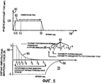
фиг. 5 - график сигналов импульсных вихревых токов (PEC), используемый для объяснения принципа действия PIGа согласно типичному примеру осуществления настоящего изобретения;FIG. 5 is a graph of pulse eddy current (PEC) signals used to explain the principle of operation of a PIG according to a typical embodiment of the present invention;
фиг. 6 - блок-схема, иллюстрирующая типичный пример осуществления электрической схемы, которая может быть использована для обработки данных, полученных с помощью PIGа согласно типичному примеру осуществления настоящего изобретения; иFIG. 6 is a block diagram illustrating a typical embodiment of an electrical circuit that can be used to process data obtained using a PIG according to a typical embodiment of the present invention; and
фиг. 7 - блок-схема последовательности типичных этапов работы датчика PEC согласно типичному примеру осуществления настоящего изобретения.FIG. 7 is a flowchart of typical steps for operating a PEC sensor according to a typical embodiment of the present invention.
ПОДРОБНОЕ ОПИСАНИЕDETAILED DESCRIPTION
Типичные примеры осуществления настоящего изобретения касаются проверки эффективности трубопроводов. В частности, прибор контроля трубопроводов (PIG) содержит множество ступеней датчиков, каждая из которых содержит множество секторов датчиков. Для получения информации о возможных дефектах или ухудшении состояния стенок трубопровода от датчиков в PIGе используется технология импульсных вихревых токов (PEC). Как поясняется ниже, использование технологии PEC позволяет размещать датчики таким образом, что PIG может находиться как в сжатом состоянии, так и в растянутом состоянии. В сжатом состоянии PIG может проходить относительно остроугольные изгибы в трубопроводе.Typical embodiments of the present invention relate to piping efficiency testing. In particular, the Pipeline Monitoring Instrument (PIG) comprises a plurality of sensor stages, each of which contains a plurality of sensor sectors. In order to obtain information about possible defects or deterioration of the pipe walls from sensors, PIG uses the technology of pulsed eddy currents (PEC). As explained below, the use of PEC technology allows the sensors to be placed in such a way that the PIG can be both in a compressed state and in a stretched state. In a compressed state, the PIG can undergo relatively acute-angled bends in the pipeline.
На фиг. 1 представлен схематичный вид системы контроля трубопроводов, в целом обозначенной ссылочной позицией 10. Система 10 контроля трубопроводов, адаптированная к контролю трубопровода 12, содержит прибор 14 контроля трубопроводов (PIG). PIG 14 представляет собой сканирующее устройство, размещаемое в трубопроводе и используемое для сбора данных о состоянии стенок трубопровода 12. Данные могут быть подвергнуты анализу с целью определения потенциальных дефектов типа слабых мест и т.п. в стенках трубопровода. PIG 14 может перемещаться по длине трубопровода с потоком текучей среды в трубопроводе. В типичном примере осуществления, иллюстрированном на фиг. 1, для получения данных о состоянии стенок трубопровода 12 в PIGе 14 используются датчики или зонды импульсных вихревых токов (PEC).In FIG. 1 is a schematic view of a piping control system, generally indicated at 10.
PIG 14 содержит первую ступень 16 датчиков и вторую ступень 18 датчиков. Конструкция первой ступени 16 датчиков и второй ступени 18 датчиков такова, что каждая из них может находиться в растянутом состоянии и в сжатом состоянии. В сжатом состоянии первая ступень 16 датчиков и вторая ступень 18 датчиков могут иметь достаточно малый диаметр, чтобы обеспечить PIG 14 возможность прохождения относительно остроугольных изгибов внутри трубопровода 12 по сравнению с препятствиями, которые этот прибор может проходить при растянутом состоянии ступеней 16, 18 датчиков.PIG 14 comprises a
В примере осуществления, иллюстрированном на фиг. 1, PIG 14 дополнительно содержит позиционный компонент (POC) 20, который определяет положение и ориентацию PIG 14 в трубопроводе 12. Кроме того, PIG 14 включает в себя систему 22 сбора данных (DAS) для приема данных, собираемых первой ступенью 16 датчиков и второй ступенью 18 датчиков. Источник 24 питания (PS) обеспечивает подачу питания на первую ступень 16 датчиков, вторую ступень 18 датчиков, POC 20 и DAS 22, а также и на другие ассоциированные компоненты PIG 14. Специалистам в данной области техники очевидно, что PIG 14 может дополнительно содержать дополнительные компоненты типа встроенных часов для проставление метки времени на каждую запись, полученную с помощью DAS 22 или т.п. Точно так же система 10 контроля трубопроводов может включать в себя дополнительные компоненты, подобные магнитометрам или магнитным регистраторам, одометрам и внешним часам, предназначенным для записи положения и всего расстояния, пройденного прибором PIG 14.In the embodiment illustrated in FIG. 1,
Фиг. 2 - поперечное сечение PIGа 14, представленного на фиг. 1, проходящее через центральную ось 36 прибора. Чертеж в целом обозначен ссылочной позицией 26. Поперечное сечение, представленное на фиг. 2, иллюстрирует работу одной из ступеней датчиков, представленных на фиг. 1. В иллюстративных целях на фиг. 2 представлена первая ступень 16 датчиков (фиг. 1). Первая ступень 16 датчиков содержит множество секторов 28, 30, 32 и 34 датчиков. Секторы 28, 30, 32 и 34 датчиков, показанные на фиг. 2 штрихпунктирными линиями, находятся в сжатом состоянии. Позициями 128, 130, 132 и 134 обозначены соответственно те же самые секторы датчиков, находящиеся в растянутом положении относительно центральной оси 36.FIG. 2 is a cross-sectional view of the PIG-14 of FIG. 1 passing through the
Каждый из множества секторов 28, 30, 32 и 34 датчиков прикреплен к механизму 38 расширения, который может содержать пружину, гидравлическую систему или т.п., для перемещения соответствующего сектора датчиков между сжатым состоянием и растянутым состоянием. В сжатое положении диаметр PIGа 14 может составлять приблизительно 60-70% от его значения в растянутом состоянии. Перемещение ступеней 16, 18 датчиков в сжатое состояние позволяет PIGу 14 свободно проходить через относительно остроугольные изгибы или другие препятствия в трубопроводе 12.Each of the plurality of
Фиг. 3 - схематичный вид, демонстрирующий ступени 16, 18 датчиков многоступенчатого PIGа 14, представленного на фиг. 1. Чертеж в целом обозначен ссылочной позицией 40. Первая ступень 16 датчиков и вторая ступень 18 датчиков показаны на фиг. 3 штриховыми линиями. Первая ступень 16 датчиков содержит секторы 30, 32 и 34 датчиков. Каждый из секторов датчиков 30, 32 и 34 содержит множество датчиков 42, которые в данном документе могут также именоваться приемниками. Точно так же вторая ступень 18 датчиков содержит сектор 44 датчиков и сектор 46 датчиков. Каждый из секторов 44, 46 датчиков содержит множество приемников 42. В типичном примере осуществления датчики размещены на секторах датчиков первой ступени 16 датчиков и второй ступени 18 датчиков так, что в растянутом состоянии и первая ступень 16 датчиков, и вторая ступень 18 датчиков могут полностью охватывать трубопровод по окружности. Кроме того, положение секторов 44, 46 датчиков относительно секторов 30, 32 и 34 датчиков может быть таким, что при растянутом состоянии обеих ступеней датчиков секторы 44 и 46 датчиков второй ступени 18 датчиков будут охватывать участки окружности трубопровода, соответствующие зазорам между секторами 30, 32 и 34 датчиков первой ступени 16 датчиков. Следовательно, при растянутом состоянии ступеней 16, 18 датчиков может быть обеспечен полный охват трубопровода 12 по окружности.FIG. 3 is a schematic view showing the
Для получения данных о состоянии трубопровода 12 через посредство датчиков целесообразно, чтобы PIG 14 (фиг. 1) был адаптирован к использованию технологии возбуждения импульсных вихревых токов (PEC). В системе PEC используется направление сигналов PEC в сторону стенок трубопровода 12, а также прием и измерение отраженных сигналов. Технология PEC отличается от технологии возбуждения вихревых токов автономным источником поля. В системе возбуждения вихревых токов автономным источником поля возбуждение катушки возбуждения обеспечивается сигналом синусоидального тока. Для получения эффективных результатов катушка возбуждения должна быть физически отделена от датчиков относительно большим расстоянием, чтобы облегчить прием отраженного сигнала от трубопровода, подвергаемого проверке.To obtain data on the condition of the
В отличие от этого в системе PEC входной сигнал синусоидальной формы замещается последовательностью импульсов тока возбуждения. Возбуждение катушки возбуждения осуществляется в течение длительности начального импульса. Затем предусмотрена стабилизация тока. Отраженные сигналы достигают датчиков в течение периода стабилизации. Это позволяет наблюдать относительно малые изменения, соответствующие потенциальному повреждению в трубопроводе 12. Кроме того, система PEC позволяет сделать PIG 14 более компактным, так как катушка возбуждения может быть размещена на более близком расстоянии от принимающих датчиков. В типичном примере осуществления катушка возбуждения может быть размещена рядом с одним или более из принимающих датчиков.In contrast, in the PEC system, the sinusoidal input signal is replaced by a train of excitation current pulses. Excitation of the excitation coil is carried out during the duration of the initial pulse. Then, current stabilization is provided. The reflected signals reach the sensors during the stabilization period. This allows you to observe relatively small changes corresponding to potential damage in the
Для ясности на фиг. 3 представлены только три сектора датчиков первой ступени 16 датчиков и два сектора датчиков второй ступени 18 датчиков. Специалистам в данной области техники очевидно, что точное число секторов датчиков в ступени датчиков не является существенной особенностью настоящего изобретения. Более того, в основу выбора числа секторов датчиков может быть положен ряд конструкционных соображений, включая наличие достаточного числа секторов датчиков во второй ступени датчиков для обеспечения соответствия числу зазоров между секторами датчиков в первой ступени датчиков при растянутом состоянии ступеней датчиков.For clarity, FIG. 3 shows only three sensor sectors of the
Описываемое выше расположение датчиков обеспечивает возможность равномерного охвата поверхности во время контроля трубопровода. Если в качестве примера предположить, что в каждой ступени PIGа имеется четыре ступени, то диаметр можно считать разделенным на четыре шага в окружном направлении между секторами датчиков. Для сбора импульсных откликов от стенки трубопровода, имеющего шаг 4,9 мм в окружном направлении, в трубопроводе с внутренним диаметром 300 мм может потребоваться в общей сложности 192 приемных датчика или преобразователя. Если предположить наличие двух ступеней датчиков и четырех сектора датчиков в каждой ступени, то каждый сектор может иметь 24 датчика, размещенных в виде четырех линеек из шести датчиков, расположенных в сетке пространственных координат с шагом 19,6 мм. Для обеспечения полного охвата поверхности трубопровода 12 с сеткой, деление которой составляет 4,9 мм, линейки могут быть последовательно смещены в окружном направлении на 4,9 мм.The arrangement of sensors described above provides the possibility of uniform coverage of the surface during pipeline control. If, as an example, it is assumed that there are four steps in each PIG stage, then the diameter can be considered divided into four steps in the circumferential direction between the sectors of the sensors. A total of 192 receiving sensors or transducers may be required to collect impulse responses from a wall of a pipe having a 4.9 mm pitch in the circumferential direction in a pipe with an internal diameter of 300 mm. If we assume that there are two sensor stages and four sensor sectors in each stage, then each sector can have 24 sensors placed in the form of four rulers of six sensors located in a spatial coordinate grid with a pitch of 19.6 mm. To ensure full coverage of the surface of the
Комбинация катушки возбуждения большой площади и относительно малых приемных датчиков может обеспечить высокое разрешение изображения стенки трубопровода 12, формируемого вихревыми токами. В описываемом примере для одновременного возбуждения всех восьми катушек возбуждения системе может потребоваться только один возбуждающий импульс. Для облегчения измерения импульсного отклика на вихревые токи, индуцированные только соседней катушкой возбуждения, датчики могут быть размещены настолько близко к виткам катушки возбуждения, насколько это возможно.The combination of a large area excitation coil and relatively small receiving sensors can provide a high resolution image of the
Фиг. 4 - схематичное изображение сектора датчиков многоступенчатого PIGа согласно типичному примеру осуществления настоящего изобретения. Чертеж в целом обозначен ссылочной позицией 48. Фиг. 4 иллюстрирует типичный пример осуществления, который может быть использован для каждого из секторов датчиков, представленных на фиг. 3. В иллюстративных целях на фиг. 4 представлен сектор 30 датчиков первой ступени 16 датчиков. Средством возбуждения соответствующих датчиков в секторе 30 датчиков служит катушка 74 возбуждения. Катушка возбуждения используется для инжекции импульсного магнитного потока в стенку трубопровода 12. Как поясняется ниже со ссылками на фиг. 5, эту инжекцию целесообразно осуществлять с помощью прямоугольного импульса электрического тока от генератора импульсов (см. фиг. 6).FIG. 4 is a schematic illustration of a multi-stage PIG sensor sector according to a typical embodiment of the present invention. The drawing is generally indicated at 48. FIG. 4 illustrates a typical embodiment that may be used for each of the sensor sectors of FIG. 3. For illustrative purposes, in FIG. 4 shows a
Сектор 30 датчиков содержит множество преобразователей 50, 52, 54, 56, 58 и 60, размещенных в виде вертикальных линеек, как показано на фиг. 4. На фиг. 4 каждый из преобразователей 50, 52, 54, 56, 58 и 60 имеет свою собственную ссылочную позицию, но в целом они соответствуют датчикам 42, представленным на фиг. 3. В качестве примера на фиг. 4 показан сектор 30 датчиков, однако подобным образом могут быть размещены и другие секторы датчиков данной ступени датчиков. Линейки, образованные преобразователями 50, 52, 54, 56 и 58, смещены одна относительно другой на четверти диаметра преобразователей. То есть преобразователи размещены так, что центровая линия 64 преобразователя 50 (в составе второй линейки слева) проходит через преобразователь 58 (четвертой и последней линейки слева) приблизительно на расстоянии четверти диаметра от верхней части датчика 58. Центровая линия 68 датчика 52 (в составе первой линейки слева) проходит через преобразователь 58 приблизительно на расстоянии четверти диаметра от нижней части датчика 58. Центровая линия 70 преобразователя 60 (в составе третьей линейки слева) проходит между датчиком 58 и датчиком 62. Наконец, центровая линия 72 преобразователя 54 проходит через датчик 62 приблизительно на расстоянии одной четверти диаметра от верхней части датчика 62. Типичное расположение датчиков, представленное на фиг. 4, обеспечивает охват трубопровода 12 с перекрытием.The
Представленный на фиг. 5 график служит для объяснения использования технологии PEC в PIGе 14 (фиг. 1). График в целом обозначен ссылочной позицией 76. Ось 78 X в верхней части графика 76 соответствует времени в миллисекундах. Ось 80 Y в верхней части графика 76 соответствует индукционному току через катушку возбуждения типа катушки 74 возбуждения (фиг. 4). Сигнал 82 индукционного тока PEC представлен графиком в системе координат, образованной осью 78 X и осью 80 Y. На фиг. 5 показано быстрое нарастание индукционного тока приблизительно в течение 0,01 мс до относительно устойчивого уровня, длящегося приблизительно в течение 0,01-50 мс, и последующее его резкое снижение.Presented in FIG. 5, the graph serves to explain the use of PEC technology in PIG 14 (FIG. 1). The graph is generally indicated at 76. The 78 X axis at the top of
В нижней части фиг. 5 представлен соответствующий сигнал напряжения, индуцированного в приемных датчиках типа преобразователей 52, 54, 56, 58, 60 и 62, показанных на фиг. 4. Ось 86 X в нижней части графика соответствует времени в миллисекундах. Ось 88 Y соответствует сигнальному напряжению. Сигнал 90 напряжения датчиков иллюстрирует соответствующее напряжение датчиков в зависимости от сигнала индукционного тока в верхней части графика на фиг. 5. Как показано, сигнал 90 напряжения датчиков имеет относительно высокий уровень в период быстрого нарастания индукционного тока 82. Затем, в период стабилизации сигнала 82 индукционного тока PEC наблюдается медленное снижение значения сигнала 90 напряжения. Так как на сигнал, принимаемый преобразователями, могут оказывать влияние поврежденные участки трубопровода, то значение сигнала 90 напряжения датчиков в различные моменты времени может соответствовать повреждению трубопровода 12. Путем измерения значения сигнала 90 напряжения датчиков в различные моменты времени можно создать математическую модель эффективности трубопровода типа трубопровода 12. Как показано на фиг. 5, на основе измерений сигнала 90 напряжения датчиков может быть выведено уравнение аппроксимации параметризованной кривой. Во время операции измерений может быть определено и сохранено несколько параметрических коэффициентов 92, соответствующих сигналу 90 напряжения датчиков. Более того, хранение во встроенной памяти PIGа 14 только коэффициентов является выгодным с экономической точки зрения, так как позволяет сохранить данные, соответствующие представлению расширенной секции трубопровода 12, для более поздней оценки. Параметрические коэффициенты 92 могут быть позднее использованы для восстановления сигнала 90 напряжения датчиков с целью определения потенциальных аномалий на поверхности трубопровода 12.At the bottom of FIG. 5 shows the corresponding voltage signal induced in the receiving sensors of the type of converters 52, 54, 56, 58, 60, and 62 shown in FIG. 4. The 86 X axis at the bottom of the graph corresponds to the time in milliseconds. The 88 Y axis corresponds to the signal voltage. The
Для определения параметрических коэффициентов 92, характеризующих состояние трубопровода, к фактическому значению, полученному для сигнала 90 напряжения датчиков, может быть применена подпрограмма сжатия. Считается, что эта форма параметризации обеспечивает базис для достаточной оценки стенок трубопровода 12 в типичном диапазоне условий отслаивания датчика, значений проницаемости образца, его удельной проводимости и толщины, ожидаемых во время нормальной работы датчика импульсных вихревых токов для его предполагаемой работы.To determine the
Фиг. 6 - блок-схема, демонстрирующая типичный пример осуществления электрической схемы, которая может быть использована для обработки данных, полученных с помощью PIGа 14. Блок-схема в целом обозначена ссылочной позицией 110. Для подачи сигнала PEC на типичный сектор 30 датчиков модуль 112 управления адаптирован к управлению генератором 114 импульсов. В примере осуществления, иллюстрированном фиг. 6, данные от каждой из четырех линеек датчиков на секторе 30 датчиков поступают на соответствующую схему 116, 118, 120 или 122 предварительной обработки. Модули 116, 118, 120 и 122 предварительной обработки выполняют предварительную фильтрацию и ограничение амплитуды на данные. После обработки с помощью схем предварительной обработки данные поступают на соответствующие схемы 124, 126, 128 или 130 полиномиальной аппроксимации. Алгоритм обработки, используемый схемами 124, 126, 128 и 130 полиномиальной аппроксимации, может обеспечивать аппроксимацию полиномиальной кривой к отклику на импульсные вихревые токи, позволяющую определять полиномиальные коэффициенты, рассмотренные выше со ссылками на фиг. 5. Полученные коэффициенты записываются для каждого датчика в каждой точке замера во встроенное устройство хранения данных типа системы 22 сбора данных. Хранение только полиномиальных коэффициентов позволяет уменьшить объем данных, хранимых во встроенном запоминающем устройстве, в 50-100 раз. Для уменьшения числа каналов сбора данных во время сбора данных может быть использовано дополнительное мультиплексирование. Наконец, описанный алгоритм включает в себя в качестве части подпрограммы аппроксимации кривых функцию низкочастотной фильтрации.FIG. 6 is a block diagram showing a typical embodiment of an electrical circuit that can be used to process data obtained using
По окончании контроля трубопровода система 22 сбора данных может быть подключена к компьютеру для восстановления собранных данных. Если данные соответствуют параметрическим коэффициентам, как описывается выше, то с целью вычисления значения толщины в любой точке, подвергнутой контролю, к полиномиальным коэффициентам применяется передаточная функция. Коэффициенты полученного сигнала используются для аппроксимации нелинейной передаточной функции, связывающей коэффициенты аппроксимации с толщиной, проницаемостью, удельной проводимостью и отслаиванием контрольных образцов, отклики от которых были подвергнуты измерению. При проведении последующих операций контроля трубопровода с неизвестными физическими параметрами осуществляется параметризация измеренного отклика на импульсные вихревые токи и для интерпретации коэффициентов аппроксимации и оценки физических параметров и отслаивания датчика используется предварительно вычисленная передаточная функция. Для создания соответствующей передаточной функции для каждого датчика согласно его положению на секторе датчиков и на ступени датчиков может быть разработано заказное программное обеспечение. Использование вихревых токов позволяет осуществлять построение и анализ двумерных изображений поверхности трубопровода, подвергаемого контролю. Для локализации мест нежелательного истончения стенок могут быть использованы традиционные способы обработки и анализа изображений. Такие места могут быть подвергнуты ремонтным операциям.At the end of the pipeline inspection, the
На фиг. 7 представлена блок-схема последовательности типичных этапов работы датчика PEC согласно типичному примеру осуществления настоящего изобретения. В целом эта блок-схема обозначена ссылочной позицией 132. Процесс начинается с этапа 134. На этапе 136 устройство измерения импульсных вихревых токов типа PIGа, представленного на фиг. 1, проходит через трубопровод. Как описывается выше, устройство измерения импульсных вихревых токов содержит множество ступеней. Каждая из множества ступеней адаптирована к перемещению между сжатым состоянием, при котором множество датчиков размещено вокруг, по меньшей мере, участка окружности каждой из множества ступеней без зазора между ними, и растянутым состоянием, при котором между датчиками, установленными на каждой из множества ступеней, существует, по меньшей мере, один зазор. Множество датчиков размещено так, что зазор между датчиками, размещенными вокруг первой одной из множества ступеней в растянутом состоянии совмещен с и смещен в продольном направлении от местоположения, по меньшей мере, некоторых из множества датчиков вокруг, по меньшей мере, второй одной из множества ступеней.In FIG. 7 is a flowchart of typical steps for operating a PEC sensor according to a typical embodiment of the present invention. In general, this flowchart is denoted by
На этапе 138 устройство измерения импульсного вихревого тока размещается в сжатом состоянии для облегчения прохождения через суженный участок трубопровода.At step 138, the pulse eddy current measurement device is placed in a compressed state to facilitate passage through a narrowed portion of the pipeline.
Выше в данном документе были проиллюстрированы и описаны только некоторые признаки изобретения, однако специалистам в данной области техники очевидна возможность внесения в него различных изменений и дополнений. Поэтому следует понимать, что прилагаемая формула изобретения предполагает охват всех таких изменений и дополнений, не выходящих за пределы существа изобретения.Above in this document, only certain features of the invention were illustrated and described, however, it is obvious to those skilled in the art that various changes and additions can be made thereto. Therefore, it should be understood that the appended claims are intended to encompass all such changes and additions that are within the scope of the invention.
Claims (22)
множество ступеней, разнесенных в продольном направлении одна от другой и адаптированных к перемещению между сжатым состоянием и растянутым состоянием; и множество датчиков импульсных вихревых токов, размещенных вокруг, по меньшей мере, участка окружности каждой из множества ступеней в сжатом состоянии, по меньшей мере, с одним зазором между датчиками импульсных вихревых токов в каждой из множества ступеней в растянутом состоянии, причем множество датчиков импульсных вихревых токов размещено так, что, по меньшей мере, один зазор в первой одной из множества ступеней совмещен с участком второй одной из множества ступеней, имеющей размещенные на ней датчики импульсных вихревых токов, так, что полный охват трубопровода по окружности обеспечен посредством датчиков импульсных вихревых токов.1. A device for monitoring pipelines by pulsed eddy currents, containing
many steps spaced in the longitudinal direction from one another and adapted to move between the compressed state and the extended state; and a plurality of pulsed eddy current sensors located around at least a circumferential portion of each of the plurality of steps in a compressed state, with at least one gap between the pulsed eddy current sensors in each of the plurality of stages in a stretched state, the plurality of pulsed eddy current sensors currents is arranged so that at least one gap in the first one of the many stages is aligned with the section of the second one of the many stages having pulsed eddy current sensors located on it, so then the full coverage of the pipeline around the circumference is provided by means of pulsed eddy current sensors.
множество ступеней, разнесенных в продольном направлении одна от другой и адаптированных к перемещению между сжатым состоянием и растянутым состоянием; и множество датчиков импульсных вихревых токов, размещенных вокруг, по меньшей мере, участка окружности каждой из множества ступеней в сжатом состоянии, по меньшей мере, с одним зазором между датчиками импульсных вихревых токов в каждой из множества ступеней в растянутом состоянии, причем множество датчиков импульсных вихревых токов размещено так, что, по меньшей мере, один зазор в первой одной из множества ступеней совмещен с участком второй одной из множества ступеней, имеющей размещенные на ней датчики импульсных вихревых токов и так, что полный охват трубопровода по окружности обеспечен посредством датчиков импульсных вихревых токов;
модуль сбора данных, который адаптирован к приему данных, соответствующих состоянию трубопровода, от множества датчиков; и
источник питания, который адаптирован к подаче питания на модуль сбора данных.9. A piping control device (PIG) comprising
many steps spaced in the longitudinal direction from one another and adapted to move between the compressed state and the extended state; and a plurality of pulsed eddy current sensors located around at least a circumferential portion of each of the plurality of steps in a compressed state, with at least one gap between the pulsed eddy current sensors in each of the plurality of stages in a stretched state, the plurality of pulsed eddy current sensors the currents are arranged so that at least one gap in the first one of the many stages is aligned with the section of the second one of the many stages having pulsed eddy current sensors on it and so that full coverage of the pipeline around the circumference is provided by means of pulsed eddy current sensors;
a data collection module that is adapted to receive data corresponding to the state of the pipeline from a plurality of sensors; and
a power supply that is adapted to supply power to the data acquisition module.
перемещают устройство измерения импульсных вихревых токов через трубопровод, где устройство измерения импульсных вихревых токов содержит множество ступеней, причем каждая из множества ступеней адаптирована к перемещению между сжатым состоянием, при котором множество датчиков импульсных вихревых токов размещено вокруг, по меньшей мере, участка окружности каждой из множества ступеней без зазора между ними, и растянутым состоянием, при котором между датчиками, установленными на каждой из множества ступеней, существует, по меньшей мере, один зазор и множество датчиков импульсных вихревых токов размещено так, что зазор между датчиками импульсных вихревых токов, размещенными вокруг первой одной из множества ступеней в растянутом состоянии, совмещен с и смещен в продольном направлении от местоположения, по меньшей мере, некоторых из множества датчиков импульсных вихревых токов вокруг, по меньшей мере, второй одной из множества ступеней так, что полный охват трубопровода по окружности обеспечен посредством датчиков импульсных вихревых токов; и размещают устройство измерения импульсных вихревых токов в сжатом состоянии для прохождения через суженный участок трубопровода.18. A method for evaluating a pipeline, comprising the steps of:
moving the pulse eddy current measuring device through a pipeline, where the pulse eddy current measuring device comprises a plurality of steps, each of the plurality of steps being adapted to move between a compressed state in which a plurality of eddy current pulse transducers are placed around at least a portion of a circle of each of the plurality steps without a gap between them, and a stretched state in which between the sensors installed on each of the many steps there is at least one gap and a plurality of pulsed eddy current sensors are arranged such that the gap between the pulsed eddy current sensors placed around the first one of the plurality of steps in an extended state is aligned with and offset in the longitudinal direction from the location of at least some of the plurality of pulsed eddy sensors currents around at least the second one of the many stages so that the full coverage of the pipeline around the circumference is provided by means of pulsed eddy current sensors; and place the device for measuring pulsed eddy currents in a compressed state for passage through a narrowed section of the pipeline.
Applications Claiming Priority (2)
| Application Number | Priority Date | Filing Date | Title |
|---|---|---|---|
| US11/290,916 US7402999B2 (en) | 2005-11-30 | 2005-11-30 | Pulsed eddy current pipeline inspection system and method |
| US11/290,916 | 2005-11-30 |
Publications (2)
| Publication Number | Publication Date |
|---|---|
| RU2008126263A RU2008126263A (en) | 2010-01-10 |
| RU2419787C2 true RU2419787C2 (en) | 2011-05-27 |
Family
ID=37866336
Family Applications (1)
| Application Number | Title | Priority Date | Filing Date |
|---|---|---|---|
| RU2008126263/28A RU2419787C2 (en) | 2005-11-30 | 2006-11-29 | System and method to control pipelines by pulsed eddy currents |
Country Status (8)
| Country | Link |
|---|---|
| US (1) | US7402999B2 (en) |
| EP (1) | EP1957968A1 (en) |
| JP (1) | JP5216598B2 (en) |
| CN (2) | CN101360995A (en) |
| CA (1) | CA2630050C (en) |
| NO (1) | NO20082653L (en) |
| RU (1) | RU2419787C2 (en) |
| WO (1) | WO2007064677A1 (en) |
Cited By (2)
| Publication number | Priority date | Publication date | Assignee | Title |
|---|---|---|---|---|
| RU2688030C1 (en) * | 2018-06-27 | 2019-05-17 | Дмитрий Леонидович Грохольский | Control non-uniformity method of wall thickness of pipelines |
| RU2703496C1 (en) * | 2016-07-01 | 2019-10-17 | Иллинойс Тул Воркс Инк. | Integrated system and method for three-axis scanning in situ and detection of defects in object during static and cyclic test |
Families Citing this family (25)
| Publication number | Priority date | Publication date | Assignee | Title |
|---|---|---|---|---|
| US7706988B2 (en) * | 2008-03-14 | 2010-04-27 | Blade Energy Partners, Inc. | Method for improved crack detection and discrimination using circumferential magnetic flux leakage |
| FR2931242B1 (en) * | 2008-05-14 | 2010-06-11 | Snecma | PROBE INTENDED FOR CURRENT FOUCAULT CONTROL OF THE SURFACE OF A CIRCONFERENTIAL ALVEOLE OF A TURBOREACTOR DISC |
| US8378667B2 (en) * | 2009-05-22 | 2013-02-19 | Tdw Delaware Inc. | System and method for detecting the passage of an object in pipeline including shielded magnetometer and a microcontroller with adaptive thresholding detection means |
| US8264221B2 (en) * | 2009-07-31 | 2012-09-11 | Olympus Ndt | Eddy current probe assembly adjustable for inspecting test objects of different sizes |
| WO2011020059A1 (en) * | 2009-08-14 | 2011-02-17 | Paul Lott | Pipeline inspection apparatus and method |
| JP5562629B2 (en) * | 2009-12-22 | 2014-07-30 | 三菱重工業株式会社 | Flaw detection apparatus and flaw detection method |
| US8633713B2 (en) * | 2011-04-11 | 2014-01-21 | Crts, Inc. | Internal pipe coating inspection robot |
| JP6006990B2 (en) * | 2011-06-10 | 2016-10-12 | 日立Geニュークリア・エナジー株式会社 | Eddy current testing probe |
| US8884614B2 (en) * | 2011-10-31 | 2014-11-11 | General Electric Company | Eddy current array probe |
| WO2013190504A1 (en) * | 2012-06-21 | 2013-12-27 | Eddyfi Ndt Inc. | High resolution eddy current array probe |
| FR3008490B1 (en) * | 2013-07-10 | 2015-08-07 | Snecma | DEVICE FOR INSPECTING A SURFACE OF AN ELECTRICALLY CONDUCTIVE PIECE |
| JP2017138099A (en) * | 2014-06-19 | 2017-08-10 | コニカミノルタ株式会社 | Nondestructive inspection apparatus |
| MX2017000035A (en) * | 2014-07-11 | 2017-04-10 | Halliburton Energy Services Inc | Micro-focused imaging of wellbore pipe defects. |
| WO2016057814A1 (en) * | 2014-10-10 | 2016-04-14 | Exxam Systems, LLC | Eddy current pipeline inspection apparatus and method |
| CN105334260A (en) * | 2015-11-09 | 2016-02-17 | 四川大学 | Steel tube pulse magnetization magnetic flux leakage detecting device |
| CA2951848C (en) | 2015-12-15 | 2024-01-16 | Eddyfi Ndt Inc. | Pulsed eddy current testing with dual-purpose coils |
| US10302594B2 (en) * | 2016-02-01 | 2019-05-28 | General Electric Technology Gmbh | Apparatus and method for determining the integrity of a tube |
| US10401325B2 (en) | 2016-08-11 | 2019-09-03 | Novitech, Inc. | Magnetizers for pigging tools |
| US10260854B2 (en) | 2016-12-07 | 2019-04-16 | Probe Technology Services, Inc. | Pulsed eddy current casing inspection tool |
| US10746698B2 (en) | 2017-01-31 | 2020-08-18 | Exxam Systems, LLC | Eddy current pipeline inspection using swept frequency |
| CN109491306B (en) * | 2017-09-11 | 2024-01-23 | 清华大学 | Dynamic magnetic detection probe and electromagnetic array method |
| CN108303086B (en) * | 2018-02-09 | 2023-12-15 | 北京零偏科技有限责任公司 | Built-in underground pipeline inertial positioning instrument of odometer |
| WO2020028990A1 (en) * | 2018-08-08 | 2020-02-13 | Pure Technologies Ltd. | Method and apparatus to detect flaws in metallic pipe |
| CN113702490B (en) * | 2021-08-27 | 2024-04-30 | 重庆邮电大学 | Method for estimating corrosion amount of concrete internal steel bars based on eddy current heat conduction |
| US12523633B2 (en) | 2024-02-06 | 2026-01-13 | Novitech Inc. | Magnetizers for pigging tools having rotational elements |
Citations (4)
| Publication number | Priority date | Publication date | Assignee | Title |
|---|---|---|---|---|
| US3225293A (en) * | 1964-02-20 | 1965-12-21 | Fenton M Wood | Apparatus for inspecting pipe for defects |
| WO1995000840A1 (en) * | 1993-06-21 | 1995-01-05 | Atlantic Richfield Company | Detection of cracks with transient electromagnetic diffusion inspection method |
| US6196075B1 (en) * | 1997-10-22 | 2001-03-06 | Pipetronix Gmbh | Device for inspection of pipes |
| RU2240549C1 (en) * | 2003-09-25 | 2004-11-20 | ЗАО "Нефтегазкомплектсервис" | Pipe flaw detector |
Family Cites Families (37)
| Publication number | Priority date | Publication date | Assignee | Title |
|---|---|---|---|---|
| US3483466A (en) * | 1967-11-03 | 1969-12-09 | American Mach & Foundry | Pipeline inspection apparatus for detection of longitudinal defects |
| US3539915A (en) * | 1967-11-03 | 1970-11-10 | American Mach & Foundry | Pipeline inspection apparatus for detection of longitudinal defects by flux leakage inspection of circumferential magnetic field |
| US3967194A (en) * | 1974-03-15 | 1976-06-29 | Vetco Offshore Industries | Method for flaw location in a magnetizable pipeline by use of magnetic markers positioned outside of said pipeline |
| DE3511076A1 (en) * | 1985-03-27 | 1986-10-09 | Kopp AG International Pipeline Services, 4450 Lingen | MOLCH FOR ELECTROMAGNETIC TESTS ON PIPELINE WALLS OF STEEL AND METHOD THEREFOR |
| US4675604A (en) * | 1985-08-28 | 1987-06-23 | Exxon Production Research Co. | Computerized and motorized electromagnetic flux leakage internal diameter tubular inspection device |
| US4808924A (en) * | 1987-02-19 | 1989-02-28 | Atomic Energy Of Canada Limited | Circumferentially compensating eddy current probe with alternately polarized transmit coils and receiver coils |
| GB2219975B (en) | 1988-06-23 | 1992-05-20 | Hodgkinson & Corby Limited | Standing frame assembly |
| FR2668605B1 (en) * | 1990-10-31 | 1994-03-18 | Commissariat A Energie Atomique | HOSE TUBE INSPECTION PROBE WITH ROTATING CONTROL HEAD. |
| JPH0577760U (en) * | 1991-05-28 | 1993-10-22 | 原子燃料工業株式会社 | Metal thin tube inspection device |
| CA2076205C (en) * | 1992-08-14 | 1999-04-20 | Valentino S. Cecco | Differential transmit-receive eddy current probe incorporating bracelets of multi-coil units |
| JP3180853B2 (en) * | 1993-02-02 | 2001-06-25 | 東京瓦斯株式会社 | Receiving unit in remote field eddy current type flaw detector |
| US5565633A (en) * | 1993-07-30 | 1996-10-15 | Wernicke; Timothy K. | Spiral tractor apparatus and method |
| US5479100A (en) * | 1994-05-10 | 1995-12-26 | Gas Research Institute | Method for detecting anomalies in pipes |
| JP3428734B2 (en) * | 1994-08-01 | 2003-07-22 | 東京瓦斯株式会社 | Metal tube flaw detector and metal tube flaw detection method |
| JPH0949825A (en) * | 1995-08-04 | 1997-02-18 | Genshiryoku Eng:Kk | Eddy current flaw detection probe |
| JPH10160710A (en) * | 1996-11-27 | 1998-06-19 | Nippon Hihakai Keisoku Kenkyusho:Kk | Split type flaw detection sensor and conductive tube flaw detection method |
| US6232773B1 (en) * | 1998-09-05 | 2001-05-15 | Bj Services Company | Consistent drag floating backing bar system for pipeline pigs and method for using the same |
| AUPP813499A0 (en) * | 1999-01-13 | 1999-02-04 | Rock Solid Research Pty. Ltd. | A subsurface pipeline inspection probe |
| US6429759B1 (en) * | 2000-02-14 | 2002-08-06 | General Electric Company | Split and angled contacts |
| JP2002005893A (en) * | 2000-06-20 | 2002-01-09 | Tokyo Gas Co Ltd | Defect determination method and sensor calibration method in pipe inspection device |
| US6414483B1 (en) * | 2000-07-27 | 2002-07-02 | General Electric Company | Eddy current inspection method and apparatus for detecting flaws in an electrically conductive component |
| JP2002062279A (en) * | 2000-08-22 | 2002-02-28 | Tokyo Gas Co Ltd | Leakage flux pig |
| US6720775B2 (en) * | 2001-06-12 | 2004-04-13 | General Electric Company | Pulsed eddy current two-dimensional sensor array inspection probe and system |
| US6911826B2 (en) * | 2001-06-12 | 2005-06-28 | General Electric Company | Pulsed eddy current sensor probes and inspection methods |
| US6451089B1 (en) * | 2001-07-25 | 2002-09-17 | Phelps Dodge Corporation | Process for direct electrowinning of copper |
| US6670808B2 (en) * | 2001-08-27 | 2003-12-30 | General Electric Company | Self reference eddy current probe, measurement system, and measurement method |
| US6545469B1 (en) * | 2001-10-31 | 2003-04-08 | General Electric Company | Embedded eddy current inspection apparatus, system, and method |
| AU2003228219A1 (en) * | 2002-02-25 | 2003-09-09 | General Electric Company | Method for communicating information bundled in digital message packets |
| US6707297B2 (en) * | 2002-04-15 | 2004-03-16 | General Electric Company | Method for in-situ eddy current inspection of coated components in turbine engines |
| US6794963B2 (en) * | 2002-04-24 | 2004-09-21 | General Electric Company | Magnetic device for a magnetic trip unit |
| US6812697B2 (en) * | 2002-09-24 | 2004-11-02 | General Electric Company | Molded eddy current array probe |
| DE10300383B4 (en) | 2003-01-09 | 2005-05-12 | Windhoff Bahn- Und Anlagentechnik Gmbh | Pipeline pig |
| JP2004251839A (en) * | 2003-02-21 | 2004-09-09 | Jfe Steel Kk | Pipe surface inspection system |
| US6888347B2 (en) * | 2003-09-12 | 2005-05-03 | General Electric Company | Omnidirectional eddy current probes, array probes, and inspection systems |
| US6922641B2 (en) * | 2003-09-17 | 2005-07-26 | General Electric Company | System and method for monitoring defects in structures |
| US7005851B2 (en) * | 2003-09-30 | 2006-02-28 | General Electric Company | Methods and apparatus for inspection utilizing pulsed eddy current |
| US6847207B1 (en) * | 2004-04-15 | 2005-01-25 | Tdw Delaware, Inc. | ID-OD discrimination sensor concept for a magnetic flux leakage inspection tool |
-
2005
- 2005-11-30 US US11/290,916 patent/US7402999B2/en not_active Expired - Lifetime
-
2006
- 2006-11-29 CN CNA2006800515336A patent/CN101360995A/en active Pending
- 2006-11-29 JP JP2008543406A patent/JP5216598B2/en not_active Expired - Fee Related
- 2006-11-29 CA CA2630050A patent/CA2630050C/en not_active Expired - Fee Related
- 2006-11-29 RU RU2008126263/28A patent/RU2419787C2/en not_active IP Right Cessation
- 2006-11-29 EP EP06844615A patent/EP1957968A1/en not_active Ceased
- 2006-11-29 CN CN2012101251031A patent/CN102680569A/en active Pending
- 2006-11-29 WO PCT/US2006/045637 patent/WO2007064677A1/en not_active Ceased
-
2008
- 2008-06-13 NO NO20082653A patent/NO20082653L/en not_active Application Discontinuation
Patent Citations (4)
| Publication number | Priority date | Publication date | Assignee | Title |
|---|---|---|---|---|
| US3225293A (en) * | 1964-02-20 | 1965-12-21 | Fenton M Wood | Apparatus for inspecting pipe for defects |
| WO1995000840A1 (en) * | 1993-06-21 | 1995-01-05 | Atlantic Richfield Company | Detection of cracks with transient electromagnetic diffusion inspection method |
| US6196075B1 (en) * | 1997-10-22 | 2001-03-06 | Pipetronix Gmbh | Device for inspection of pipes |
| RU2240549C1 (en) * | 2003-09-25 | 2004-11-20 | ЗАО "Нефтегазкомплектсервис" | Pipe flaw detector |
Cited By (2)
| Publication number | Priority date | Publication date | Assignee | Title |
|---|---|---|---|---|
| RU2703496C1 (en) * | 2016-07-01 | 2019-10-17 | Иллинойс Тул Воркс Инк. | Integrated system and method for three-axis scanning in situ and detection of defects in object during static and cyclic test |
| RU2688030C1 (en) * | 2018-06-27 | 2019-05-17 | Дмитрий Леонидович Грохольский | Control non-uniformity method of wall thickness of pipelines |
Also Published As
| Publication number | Publication date |
|---|---|
| US20070120559A1 (en) | 2007-05-31 |
| CA2630050C (en) | 2015-08-04 |
| NO20082653L (en) | 2008-06-13 |
| CN101360995A (en) | 2009-02-04 |
| WO2007064677A1 (en) | 2007-06-07 |
| CA2630050A1 (en) | 2007-06-07 |
| US7402999B2 (en) | 2008-07-22 |
| JP2009517694A (en) | 2009-04-30 |
| EP1957968A1 (en) | 2008-08-20 |
| CN102680569A (en) | 2012-09-19 |
| JP5216598B2 (en) | 2013-06-19 |
| RU2008126263A (en) | 2010-01-10 |
Similar Documents
| Publication | Publication Date | Title |
|---|---|---|
| RU2419787C2 (en) | System and method to control pipelines by pulsed eddy currents | |
| US8949042B1 (en) | AUV pipeline inspection using magnetic tomography | |
| US5963030A (en) | Pipe inspection apparatus and process | |
| Usarek et al. | Inspection of gas pipelines using magnetic flux leakage technology | |
| JP5522699B2 (en) | Nondestructive inspection apparatus and nondestructive inspection method using pulse magnetism | |
| US7038444B2 (en) | System and method for in-line stress measurement by continuous Barkhausen method | |
| US20090031813A1 (en) | Nondestructive inspection apparatus and nondestructive inspection method using guided wave | |
| Jarvis et al. | Performance evaluation of a magnetic field measurement NDE technique using a model assisted Probability of Detection framework | |
| Brockhaus et al. | In-line inspection (ILI) methods for detecting corrosion in underground pipelines | |
| US20190178844A1 (en) | Differential magnetic evaluation for pipeline inspection | |
| Yuan et al. | Inner circumferential current field testing system with TMR sensor arrays for inner-wall cracks inspection in aluminum tubes | |
| EP4411365A1 (en) | Internal duct integrity inspection equipment using magnetic metal memory | |
| CN103512483B (en) | Overhead pipe wall thickness corrosion scanning and detecting system | |
| US7565252B2 (en) | Method for automatic differentiation of weld signals from defect signals in long-range guided-wave inspection using phase comparison | |
| US10788456B2 (en) | Eddy current inspection device for nondestructive testing | |
| Singh et al. | Development of magnetic flux leakage technique for examination of steam generator tubes of prototype fast breeder reactor | |
| Lei et al. | Ultrasonic pig for submarine oil pipeline corrosion inspection | |
| RU2724582C1 (en) | Method of non-contact detection of availability, location and degree of danger of concentrators of mechanical stresses in metal of ferromagnetic structures | |
| Khajouei et al. | Wall thinning and damage detection techniques in pipelines | |
| KR101977921B1 (en) | A nondestructive testing apparatus including spiral direction current induction means | |
| Qi | Experimental study of interference factors and simulation on oil-gas pipeline magnetic flux leakage density signal | |
| RU2838440C1 (en) | Method and device of double magnetization for detection and identification of cracks in steel pipelines | |
| Lee et al. | A review of real time visualization of eddy currents in a small bore-piping system using solid-state Hall sensor arrays | |
| MX2008007011A (en) | Pulsed eddy current pipeline inspection system and method | |
| Goldfine et al. | MWM®-Array Electromagnetic Techniques for Crack Sizing, Weld Assessment, Wall Loss/Thickness Measurement and Mechanical Damage Profilometry |
Legal Events
| Date | Code | Title | Description |
|---|---|---|---|
| MM4A | The patent is invalid due to non-payment of fees |
Effective date: 20161130 |