RU2415912C2 - Fermenter system for bio-technical processes - Google Patents
Fermenter system for bio-technical processes Download PDFInfo
- Publication number
- RU2415912C2 RU2415912C2 RU2007149323/13A RU2007149323A RU2415912C2 RU 2415912 C2 RU2415912 C2 RU 2415912C2 RU 2007149323/13 A RU2007149323/13 A RU 2007149323/13A RU 2007149323 A RU2007149323 A RU 2007149323A RU 2415912 C2 RU2415912 C2 RU 2415912C2
- Authority
- RU
- Russia
- Prior art keywords
- tank
- fermenter
- reservoir
- transparent element
- cells
- Prior art date
Links
Images
Classifications
-
- C—CHEMISTRY; METALLURGY
- C12—BIOCHEMISTRY; BEER; SPIRITS; WINE; VINEGAR; MICROBIOLOGY; ENZYMOLOGY; MUTATION OR GENETIC ENGINEERING
- C12M—APPARATUS FOR ENZYMOLOGY OR MICROBIOLOGY; APPARATUS FOR CULTURING MICROORGANISMS FOR PRODUCING BIOMASS, FOR GROWING CELLS OR FOR OBTAINING FERMENTATION OR METABOLIC PRODUCTS, i.e. BIOREACTORS OR FERMENTERS
- C12M23/00—Constructional details, e.g. recesses, hinges
- C12M23/22—Transparent or translucent parts
-
- A—HUMAN NECESSITIES
- A61—MEDICAL OR VETERINARY SCIENCE; HYGIENE
- A61P—SPECIFIC THERAPEUTIC ACTIVITY OF CHEMICAL COMPOUNDS OR MEDICINAL PREPARATIONS
- A61P31/00—Antiinfectives, i.e. antibiotics, antiseptics, chemotherapeutics
- A61P31/12—Antivirals
-
- C—CHEMISTRY; METALLURGY
- C12—BIOCHEMISTRY; BEER; SPIRITS; WINE; VINEGAR; MICROBIOLOGY; ENZYMOLOGY; MUTATION OR GENETIC ENGINEERING
- C12M—APPARATUS FOR ENZYMOLOGY OR MICROBIOLOGY; APPARATUS FOR CULTURING MICROORGANISMS FOR PRODUCING BIOMASS, FOR GROWING CELLS OR FOR OBTAINING FERMENTATION OR METABOLIC PRODUCTS, i.e. BIOREACTORS OR FERMENTERS
- C12M23/00—Constructional details, e.g. recesses, hinges
- C12M23/58—Reaction vessels connected in series or in parallel
-
- C—CHEMISTRY; METALLURGY
- C12—BIOCHEMISTRY; BEER; SPIRITS; WINE; VINEGAR; MICROBIOLOGY; ENZYMOLOGY; MUTATION OR GENETIC ENGINEERING
- C12M—APPARATUS FOR ENZYMOLOGY OR MICROBIOLOGY; APPARATUS FOR CULTURING MICROORGANISMS FOR PRODUCING BIOMASS, FOR GROWING CELLS OR FOR OBTAINING FERMENTATION OR METABOLIC PRODUCTS, i.e. BIOREACTORS OR FERMENTERS
- C12M27/00—Means for mixing, agitating or circulating fluids in the vessel
- C12M27/02—Stirrer or mobile mixing elements
-
- C—CHEMISTRY; METALLURGY
- C12—BIOCHEMISTRY; BEER; SPIRITS; WINE; VINEGAR; MICROBIOLOGY; ENZYMOLOGY; MUTATION OR GENETIC ENGINEERING
- C12M—APPARATUS FOR ENZYMOLOGY OR MICROBIOLOGY; APPARATUS FOR CULTURING MICROORGANISMS FOR PRODUCING BIOMASS, FOR GROWING CELLS OR FOR OBTAINING FERMENTATION OR METABOLIC PRODUCTS, i.e. BIOREACTORS OR FERMENTERS
- C12M41/00—Means for regulation, monitoring, measurement or control, e.g. flow regulation
- C12M41/12—Means for regulation, monitoring, measurement or control, e.g. flow regulation of temperature
- C12M41/18—Heat exchange systems, e.g. heat jackets or outer envelopes
- C12M41/22—Heat exchange systems, e.g. heat jackets or outer envelopes in contact with the bioreactor walls
Abstract
Description
Настоящее изобретение относится к системе ферментера для применения в биотехнических процессах, в частности для культивирования клеток.The present invention relates to a fermenter system for use in biotechnological processes, in particular for cell culture.
Биотехнические процессы для аэробного или анаэробного культивирования животных или микробных клеток обычно проводят в биореакторах, часто называемых ферментерами. При этом выбор конкретного биореактора имеет решающее значение для эффективности процесса. Ферментеры должны обеспечивать оптимальные условия с точки зрения выращивания микроорганизмов и метаболической активности. Можно приобрести биореакторы сравнительно небольших лабораторных размеров на 1-10 литров, а также промышленных размеров на 16000 литров и более. Точный размер ферментера зависит от годовой потребности в продукте, конкретного процесса и режима эксплуатации.Biotechnological processes for aerobic or anaerobic cultivation of animals or microbial cells are usually carried out in bioreactors, often called fermenters. In this case, the choice of a particular bioreactor is crucial for the efficiency of the process. Fermenters should provide optimal conditions in terms of microbial growth and metabolic activity. You can buy bioreactors of relatively small laboratory sizes of 1-10 liters, as well as industrial sizes of 16,000 liters or more. The exact size of the fermenter depends on the annual need for the product, the specific process and mode of operation.
Термин «ферментер» или «система ферментера» относится, в общем, к устройству, которое можно применять для аэробного или анаэробного культивирования клеток. Данная система может содержать, по меньшей мере, один резервуар ферментера, который можно герметично закрывать таким образом, что содержимое резервуара изолировано от среды снаружи системы, что исключает загрязнение определенной клеточной культуры, выращиваемой в системе ферментера. Резервуар содержит несколько впускных узлов или выпускных узлов, ведущих в/из резервуара, которые служат для подсоединения патрубков и трубопроводов для управляемого ввода и/или отведения жидкостей или газов, например, компонентов питательных сред или кислорода. Данные трубы и патрубки, подсоединенные к резервуару, также входят в состав системы ферментера. Как правило, данные части чистят и стерилизуют за один этап вместе с резервуаром.The term “fermenter” or “fermenter system” refers, in general, to a device that can be used for aerobic or anaerobic cell culture. This system may contain at least one fermenter tank, which can be hermetically sealed so that the contents of the tank are isolated from the environment outside the system, which eliminates contamination of a particular cell culture grown in the fermenter system. The tank contains several inlet nodes or outlet nodes leading to / from the tank, which are used to connect nozzles and pipelines for the controlled input and / or discharge of liquids or gases, for example, components of nutrient media or oxygen. These pipes and nozzles connected to the tank are also part of the fermenter system. As a rule, these parts are cleaned and sterilized in one step together with the tank.
Наиболее широко применяемым типом ферментера является резервуар с механическим перемешиванием. Данный тип реактора обычно состоит из цилиндрического резервуара из нержавеющей стали, который закрывают сверху, и в который установлена разнообразная арматура типа вентильной арматуры и патрубков (например, для измерительных головок или другого вспомогательного оборудования).The most widely used type of fermenter is a tank with mechanical stirring. This type of reactor usually consists of a cylindrical stainless steel tank, which is closed on top, and in which a variety of valves such as valves and nozzles are installed (for example, for measuring heads or other auxiliary equipment).
Стерильность системы ферментера является ключевым требованием для его успешной работы. В частности, в контексте производства веществ для фармацевтического применения (например, вакцин или активных средств), требуется исключить любое загрязнение клеточной культуры в ферментере. Поэтому систему ферментера в целом, содержащую вспомогательное оборудование и культуральную среду, стерилизуют перед применением. Однако известные ферментеры обладают некоторыми конструктивными недостатками, которые могут приводить к неудовлетворительной стерилизации системы ферментера перед применением, что, в свою очередь, может стать причиной загрязнения. В альтернативном варианте, загрязнение клеточной культуры в ферментере может происходить в результате этапов обработки во время работы системы.The sterility of the fermenter system is a key requirement for its successful operation. In particular, in the context of the production of substances for pharmaceutical use (for example, vaccines or active agents), any contamination of the cell culture in the fermenter must be excluded. Therefore, the fermenter system as a whole, containing auxiliary equipment and culture medium, is sterilized before use. However, known fermenters have some design flaws that can lead to poor sterilization of the fermenter system before use, which, in turn, can cause contamination. Alternatively, contamination of the cell culture in the fermenter may occur as a result of processing steps during system operation.
В связи с этим, тупики трубопроводов представляют собой распространенный источник загрязнения в системах ферментеров, применяемых в настоящее время. Тупиками трубопроводов обычно называют части труб или патрубков, или части более сложного трубопроводного сборочного узла, например, трубопроводной сети или системы каналов, которые не полностью заполняются жидкостью или газом, протекающим по ним. До таких мест не достать надлежащим образом во время стерилизации ферментера, и остатки культуральной среды от предыдущего производственного цикла могут задерживаться в данных зонах, что, в свою очередь, может вызвать загрязнение культуры при последующей ферментации с использованием данной системы. В частности, зону вентильной арматуры в трубопроводе часто нельзя стерилизовать удовлетворительно. Поэтому существует потребность в создании системы ферментера, содержащей вентильную арматуру, которая не содержит тупиков, чтобы гарантировать надлежащую стерилизацию.In this regard, pipe dead ends are a common source of contamination in the fermenter systems currently in use. Pipes are usually referred to as pipe or pipe parts, or parts of a more complex pipeline assembly, such as a pipe network or duct system, that are not completely filled with liquid or gas flowing through them. Such places cannot be reached properly during sterilization of the fermenter, and the residues of the culture medium from the previous production cycle may linger in these areas, which, in turn, can cause contamination of the culture during subsequent fermentation using this system. In particular, the valve area in the pipeline often cannot be sterilized satisfactorily. Therefore, there is a need for a fermenter system comprising valve fittings that does not contain dead ends to ensure proper sterilization.
В процессах биотехнического производства часто необходимо контролировать процесс путем оптического наблюдения за содержимым в закрытом резервуаре. Поэтому в стенку резервуара вмонтируют смотровые отверстия, которые содержат прозрачный элемент, обычно, стеклянное окно, через которое пользователь может смотреть внутрь резервуара. Из-за конденсата на прозрачном окне могут создаваться помехи видимости сквозь окно. При этом в технике известен способ установки очистителя внутри резервуара, который приводят в действие снаружи для очистки окна. Однако выяснилось, что сквозное соединение, посредством которого включают движение очистителя, оказывается причиной загрязнения, поскольку обычно трудно обеспечить эффективную стерилизацию сквозного соединения.In biotechnological production processes, it is often necessary to control the process by optical observation of the contents in a closed tank. Therefore, inspection holes are mounted in the wall of the tank, which contain a transparent element, usually a glass window through which the user can look into the tank. Condensation on the transparent window may interfere with visibility through the window. Moreover, a technique is known in the art for installing a cleaner inside a tank, which is driven externally to clean a window. However, it turned out that the through connection, through which the movement of the cleaner is turned on, is the cause of contamination, since it is usually difficult to ensure effective sterilization of the through connection.
Следовательно, существует потребность в создании резервуара ферментера, внутренний объем которого можно контролировать оптически и который можно также эффективно стерилизовать.Therefore, there is a need to create a fermenter tank, the internal volume of which can be controlled optically and which can also be effectively sterilized.
Биореакторы для культивирования клеток нуждаются в мешалке для гомогенного распределения клеток, питательных веществ, газов и тепла. В традиционных системах ферментеров вал мешалки приводится напрямую снаружи резервуара. Из-за такой конструкции существует вероятность появления загрязнений на вращающемся двухстороннем механическом уплотнении. В известных технических устройствах стерильный конденсат пара подавали между двумя парами колец во избежание загрязнения ферментационного резервуара. Однако установлено, что данный способ также не пригоден для исключения риска загрязнения. Вследствие этого существует потребность в резервуаре ферментера с усовершенствованной системой мешалки, которая не препятствует стерилизации ферментера.Cell culture bioreactors need an agitator to homogenously distribute cells, nutrients, gases and heat. In traditional fermenter systems, the agitator shaft is driven directly outside the tank. Due to this design, there is the possibility of contamination on a rotating double-sided mechanical seal. In known technical devices, sterile steam condensate was introduced between two pairs of rings in order to avoid contamination of the fermentation tank. However, it was found that this method is also not suitable to eliminate the risk of contamination. As a consequence, there is a need for a fermenter tank with an improved agitator system that does not interfere with sterilization of the fermenter.
Во время стерилизации системы ферментера пар пропускают через резервуары и трубопроводы, что приводит к значительному повышению температуры материалов системы ферментера. В частности, из-за повышения температуры расширяются стенка и трубопроводы резервуара. Данное расширение вызывает напряжение и внутренние нагрузки в материале, которые могут иметь следствием разрывы и трещины. В свою очередь, в данных разрывах и трещинах могут возникать загрязнения, которые вряд ли можно удалить просто пропусканием пара по трубопроводам системы ферментера. Следовательно, существует потребность в системе ферментера, в которой снижен риск образования трещин и разрывов во время стерилизации.During sterilization of the fermenter system, steam is passed through tanks and pipelines, which leads to a significant increase in the temperature of the materials of the fermenter system. In particular, due to an increase in temperature, the wall and pipelines of the tank expand. This expansion causes stress and internal stresses in the material, which may result in tears and cracks. In turn, contamination can occur in these breaks and cracks, which can hardly be removed simply by passing steam through the pipelines of the fermenter system. Therefore, there is a need for a fermenter system in which the risk of cracking and tearing during sterilization is reduced.
В процессах культивирования клеток культуральную жидкость часто предпочтительно перегружать из одного резервуара в другой для увеличения числа клеток. Среда для клеточной культуры в периодических процессах обладает способностью производить в конце одного цикла лишь 10-кратное увеличение количества клеток по сравнению с исходным количеством клеток. Поэтому специалисты в области культивирования клеток получают большое количество клеток в первом реакторе ферментера. Когда достигнута некоторая плотность клеток часть клеточной культуры перегружают в дополнительный резервуар ферментера со свежей культуральной средой. Такую перегрузку обычно производят несколько раз, при этом объем резервуаров ферментера увеличивается с каждым этапом перегрузки. Обычно осуществляют 3-10-кратное увеличение объема. В известных технических устройствах перекачивание облегчается за счет применения насосов, которые заставляют жидкость перетекать из одного резервуара в направлении питающего резервуара. Однако такое перекачивание приводит к образованию пены, которая может навредить клеткам в культуре из-за создания поверхностной нагрузки. Следовательно, существует также потребность в создании системы ферментера, применение которой исключает образование пены и поверхностную нагрузку.In cell culture processes, it is often preferable to transfer the culture fluid from one reservoir to another to increase the number of cells. The medium for cell culture in batch processes has the ability to produce at the end of one cycle only a 10-fold increase in the number of cells compared to the original number of cells. Therefore, specialists in the field of cell culture receive a large number of cells in the first fermenter reactor. When a certain cell density is reached, part of the cell culture is transferred to an additional fermenter reservoir with fresh culture medium. This overload is usually done several times, while the volume of the fermenter tanks increases with each stage of overload. Usually carry out a 3-10-fold increase in volume. In known technical devices, pumping is facilitated by the use of pumps that cause fluid to flow from one tank in the direction of the feed tank. However, such pumping leads to the formation of foam, which can harm cells in the culture due to the creation of a surface load. Therefore, there is also a need to create a fermenter system, the use of which eliminates the formation of foam and surface load.
Поэтому с учетом известного уровня техники, целью настоящего изобретения является создание резервуара ферментера и системы ферментера, соответственно, в которых устранены вышеупомянутые недостатки.Therefore, in view of the prior art, it is an object of the present invention to provide a fermenter reservoir and a fermenter system, respectively, in which the aforementioned disadvantages are eliminated.
В соответствии с первым аспектом настоящего изобретения, данная цель достигается с помощью резервуара ферментера, содержащего наружную стенку, заключающую объем резервуара, со смотровым отверстием, обеспеченным в наружной стенке для контроля процессов внутри объема резервуара, причем смотровое отверстие содержит прозрачный элемент, а сам прозрачный элемент снабжен нагревательным устройством.In accordance with the first aspect of the present invention, this goal is achieved by using a fermenter tank containing an outer wall enclosing the volume of the tank, with a viewing hole provided in the outer wall for monitoring processes within the volume of the tank, the viewing hole containing a transparent element and the transparent element itself equipped with a heating device.
Благодаря нагревательному устройству конденсат, который образовался на внутренней поверхности прозрачного элемента, можно удалять без потребности в механическом соединении сквозь стенку резервуара. Это снижает риск загрязнений в системе ферментера.Thanks to the heating device, the condensate that has formed on the inner surface of the transparent element can be removed without the need for a mechanical connection through the wall of the tank. This reduces the risk of contamination in the fermenter system.
В предпочтительном варианте осуществления, нагревательное устройство содержит нагревательный проводник, сформированный на поверхности прозрачного элемента. Тем самым обеспечивается преимущество, состоящее в том, что поверхность прозрачного элемента можно эффективно нагревать небольшим количеством тепловой энергии. В другом варианте осуществления нагревательное устройство содержит внутренний нагревательный проводник, который встроен в прозрачный элемент, что также приводит к эффективному нагреванию прозрачного элемента.In a preferred embodiment, the heating device comprises a heating conductor formed on the surface of the transparent element. This provides the advantage that the surface of the transparent element can be effectively heated with a small amount of thermal energy. In another embodiment, the heating device comprises an internal heating conductor that is integrated in the transparent element, which also leads to efficient heating of the transparent element.
В альтернативном варианте или дополнительно, снаружи объема резервуара можно обеспечить нагревательную лампу в качестве нагревательного устройства для нагревания прозрачного элемента. Данная схема обладает такими преимуществами, как исключение необходимости видоизменения прозрачного элемента и возможность применения общепринятых смотровых отверстий, что дает возможность дооборудовать уже установленное смотровое отверстие.Alternatively or additionally, a heating lamp can be provided outside the tank volume as a heating device for heating the transparent element. This scheme has such advantages as eliminating the need to modify the transparent element and the possibility of using generally accepted inspection openings, which makes it possible to retrofit an already installed inspection opening.
В соответствии с другим аспектом настоящего изобретения, вышеупомянутая цель достигается с помощью резервуара ферментера, содержащего наружную стенку, заключающую объем резервуара, с перемешивающим элементом, расположенным внутри объема резервуара, и приводным средством, расположенным снаружи резервуара, для вращательного привода перемешивающего элемента, причем перемешивающий элемент снабжен первым магнитным элементом, а приводное средство снабжено вторым магнитным элементом, и первый магнитный элемент и второй магнитный элемент связаны магнитными силами.In accordance with another aspect of the present invention, the aforementioned object is achieved by using a fermenter tank having an outer wall enclosing a volume of the tank, with a stirring element located inside the volume of the reservoir, and drive means located outside the reservoir for rotationally driving the stirring element, the stirring element provided with a first magnetic element, and drive means provided with a second magnetic element, and the first magnetic element and the second magnetic element connected by magnetic forces.
Благодаря магнитной связи риск загрязнения в системе ферментера существенно снижается по сравнению с известными техническими устройствами, в которых применяется механическая связь посредством вала, проходящего сквозь стенку резервуара. Магнитная связь обеспечивает возможность полной изоляции перемешивающего элемента внутри резервуара от приводного средства снаружи резервуара.Due to the magnetic coupling, the risk of contamination in the fermenter system is significantly reduced compared to the known technical devices that use mechanical coupling through a shaft passing through the tank wall. Magnetic coupling makes it possible to completely isolate the mixing element inside the tank from the drive means outside the tank.
В предпочтительном варианте осуществления перемешивающий элемент содержит вал мешалки с первым магнитным элементом, установленным на валу мешалки. Более того, приводное средство содержит ведущий вал со вторым магнитным элементом, установленным на ведущем валу.In a preferred embodiment, the stirring member comprises a stirrer shaft with a first magnetic element mounted on the stirrer shaft. Moreover, the drive means comprises a drive shaft with a second magnetic element mounted on the drive shaft.
Для обеспечения хорошей магнитной связи между магнитными элементами резервуар, в предпочтительном варианте, содержит выемку в наружной стенке, при этом выемка имеет кольцевую стенку, выступающую в объем резервуара, причем второй магнитный элемент расположен внутри выемки. При этом первый магнитный элемент расположен вблизи кольцевой стенки.To ensure good magnetic coupling between the magnetic elements, the reservoir preferably comprises a recess in the outer wall, the recess having an annular wall protruding into the volume of the reservoir, the second magnetic element being located inside the recess. In this case, the first magnetic element is located near the annular wall.
В соответствии с третьим аспектом настоящего изобретения, вышеупомянутая цель достигается посредством резервуара ферментера, содержащего наружную стенку, заключающую объем резервуара, причем стенка содержит впускной узел для ввода или отвода газа или жидкости внутрь или из объема резервуара и соединительную трубу к устройству подачи газа или жидкости, причем соединительная труба содержит первую секцию, продолжающуюся вдоль первой оси, вторую секцию, соединенную с первой секцией и продолжающуюся вдоль второй оси, причем вторая ось, по существу, перпендикулярна первой оси, и третью секцию, соединенную со второй секцией и продолжающуюся вдоль третьей оси, причем третья ось, по существу, параллельна первой оси и отнесена на некоторое расстояние от первой оси.According to a third aspect of the present invention, the aforementioned object is achieved by means of a fermenter tank having an outer wall enclosing a volume of the tank, the wall comprising an inlet assembly for introducing or discharging gas or liquid into or out of the volume of the tank and a connecting pipe to the gas or liquid supply device, moreover, the connecting pipe contains a first section extending along the first axis, a second section connected to the first section and extending along the second axis, the second axis essentially perpendicular to the first axis, and a third section connected to the second section and extending along the third axis, the third axis being substantially parallel to the first axis and spaced some distance from the first axis.
Контур, образованный первой, второй и третьей секциями, может изгибаться вдоль секций, когда секции расширяются в результате повышения температуры материала во время стерилизации. Это ослабляет напряжения в трубопроводах и, следовательно, риск образования трещин. В предпочтительном варианте осуществления во второй секции обеспечен соединительный узел, и данный соединительный узел содержит впускной вентиль. Благодаря данному конструктивному средству, впускной вентиль защищен от напряжения и внутреннего усилия, которые возникают во время стерилизации системы. Кроме того, при посредстве трех секций можно продувать соединение между впускным вентилем и резервуаром. Таким образом, трубопровод между впускным вентилем и резервуаром не образует тупика.The contour formed by the first, second, and third sections can bend along the sections when the sections expand as a result of an increase in material temperature during sterilization. This reduces stress in the pipelines and therefore the risk of cracking. In a preferred embodiment, a connecting unit is provided in the second section, and the connecting unit comprises an inlet valve. Thanks to this design tool, the inlet valve is protected from voltage and internal forces that occur during system sterilization. In addition, through the three sections, the connection between the inlet valve and the tank can be purged. Thus, the pipeline between the inlet valve and the tank does not form a dead end.
В соответствии с другим аспектом настоящего изобретения, предлагается система ферментера с резервуаром, заключающим объем резервуара, и трубопроводом для распределения жидкостей в системе ферментера, причем трубопровод содержит переключающий вентиль, причем переключающий вентиль содержит корпус вентиля, множество выпускных стоек, проходную трубу, проходящую через корпус вентиля от первого торца до второго торца, множество отверстий в корпусе вентиля и множество вентильных элементов, вставленных в отверстия, причем первый торец и второй торец сообщаются с источником подачи жидкости, отверстия сообщаются с выпускными стойками, и отверстия пересекают проходную трубу.In accordance with another aspect of the present invention, there is provided a fermenter system with a reservoir enclosing a reservoir volume and a fluid distribution pipe in the fermenter system, the conduit comprising a switching valve, the switching valve comprising a valve body, a plurality of outlet posts, a pipe passing through the body valve from the first end to the second end, many holes in the valve body and many valve elements inserted into the holes, the first end and second The swarm end communicates with the fluid supply source, the openings communicate with the outlet racks, and the openings cross the passage pipe.
Благодаря непосредственному соединению между проходной трубой и отверстиями, что обеспечивается пересечением между отверстиями и проходной трубой, вентиль в соответствии с настоящим изобретением не содержит секций, которые остаются недостижимыми во время стерилизации паром, который пропускают по проходной трубе. В связи с этим, следует упомянуть, что пересечение в контексте настоящего изобретения уже существует, если часть стенки проходной трубы пересекается отверстиями. Канал из проходной трубы в отверстия перекрывается непосредственно вентильными элементами, и не остается пространства, которое бы не продувалось, когда по трубопроводу пропускают пар.Due to the direct connection between the passage pipe and the holes, which is ensured by the intersection between the holes and the passage pipe, the valve in accordance with the present invention does not contain sections that remain unattainable during sterilization by the steam that is passed through the passage pipe. In this regard, it should be mentioned that an intersection in the context of the present invention already exists if a part of the wall of the passage pipe is intersected by openings. The channel from the passage pipe into the openings is blocked directly by the valve elements, and there is no space left that would not be blown when steam is passed through the pipeline.
В соответствии с другим аспектом настоящего изобретения, предлагается система ферментера, которая содержит первый резервуар ферментера, второй резервуар ферментера и трубу для перекачки, соединяющую первый резервуар и второй резервуар, причем труба для перекачки соединена с нижней секцией первого резервуара и нижней секцией второго резервуара.In accordance with another aspect of the present invention, there is provided a fermenter system that comprises a first fermenter tank, a second fermenter tank and a transfer pipe connecting the first tank and the second tank, the transfer pipe being connected to a lower section of the first tank and a lower section of the second tank.
Благодаря трубе для перекачки перегрузка питательной среды из первого резервуара во второй резервуар может происходить, когда повышают давление в первом резервуаре. В данном случае, повышенное давление в первом резервуаре вынуждает часть питательной среды перемещаться по трубе для перекачки во второй резервуар. При этом можно исключить насосы и, тем самым устранить обусловленный насосами эффект пенообразования.Thanks to the transfer pipe, overloading of the nutrient medium from the first tank to the second tank can occur when the pressure in the first tank is increased. In this case, the increased pressure in the first tank forces a part of the nutrient medium to move along the pipe for transferring to the second tank. In this case, pumps can be eliminated and thereby eliminate the effect of foaming caused by the pumps.
В предпочтительном варианте осуществления в трубе для перекачки обеспечен перепускной клапан, который позволяет регулировать расход потока между резервуарами. Кроме того, в предпочтительном варианте в стенке первого резервуара обеспечивают впускной узел для подачи давления, который позволяет подавать среду под давлением, предпочтительно, сжатый воздух, для повышения давления внутри первого резервуара.In a preferred embodiment, a bypass valve is provided in the transfer pipe to control the flow rate between the tanks. In addition, in a preferred embodiment, an inlet assembly for supplying pressure is provided in the wall of the first tank, which allows the medium to be supplied under pressure, preferably compressed air, to increase the pressure inside the first tank.
Вышеупомянутые аспекты, касающиеся резервуаров и систем ферментера, соответственно, можно также применять в любой их возможной комбинации.The above aspects regarding tanks and fermenter systems, respectively, can also be applied in any possible combination.
Ниже приведено описание предпочтительных вариантов осуществления настоящего изобретения со ссылками на прилагаемые чертежи, на которых:The following is a description of preferred embodiments of the present invention with reference to the accompanying drawings, in which:
Фиг.1 - вид резервуара ферментера в соответствии с настоящим изобретением;Figure 1 - view of the tank of the fermenter in accordance with the present invention;
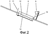
Фиг.2 - сечение смотрового отверстия, снабженного нагревательными устройствами, для резервуара ферментера в соответствии с настоящим изобретением;Figure 2 is a cross section of a viewing hole provided with heating devices for the fermenter tank in accordance with the present invention;
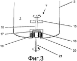
Фиг.3 - сечение нижней части резервуара ферментера в соответствии с настоящим изобретением;Figure 3 is a cross section of the lower part of the fermenter tank in accordance with the present invention;
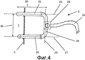
Фиг.4 - сечение впускного узла, установленного в резервуар ферментера в соответствии с настоящим изобретением;Figure 4 is a cross section of an inlet assembly mounted in a fermenter tank in accordance with the present invention;
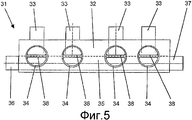
Фиг.5 - вид сверху на впускной вентиль в соответствии с настоящим изобретением, и5 is a top view of the intake valve in accordance with the present invention, and
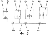
Фиг.6 - изображение системы ферментера в соответствии с настоящим изобретением, содержащей, по меньшей мере, два резервуара.6 is a depiction of a fermenter system in accordance with the present invention, containing at least two tanks.
На фиг.1 показан резервуар 1 ферментера для биотехнических процессов, который содержит наружную стенку 2. Нижняя часть резервуара 1 дополнительно снабжена второй стенкой 3, так что нижняя часть содержит двойную стенку с рубашкой. Теплоноситель можно пропускать через промежуточное пространство 4 для нагревания питательной среды внутри резервуара 1. Кроме того, анализирующие зонды 5 обеспечены внутри резервуара 1 для измерения необходимых параметров, типа температуры и давления.Figure 1 shows the
В верхней части резервуара 1 расположены два впускных патрубка 6, через которые можно подавать газ или жидкость в резервуар 1, и которые соединены с переключающим вентилем, который описан ниже. Кроме того, верхняя часть снабжена смотровым отверстием 7, которое дает возможность оптически контролировать процессы внутри резервуара 1, избегая проблему контакта содержимого с атмосферой.In the upper part of the
Смотровое отверстие 7 подробно изображено на фиг.2 и содержит прозрачный элемент 8 со стеклянным участком и изолированной рамой, например, герметично уплотненное двойное вставленное стекло и U-образные рамы из PVC (поливинилхлорида). В альтернативном варианте можно применить другие материалы вместо стекла, например пластик или боросиликатное стекло, кварц, известково-натриевое стекло или закаленное стекло.The
Из-за повышенной температуры внутри резервуара 1 во время проведения процесса на прозрачном элементе 8 может конденсироваться влага. Данный конденсат мешает пользователю смотреть сквозь прозрачный элемент 8. Для удаления конденсата с поверхности элемента 8 в данном предпочтительном варианте осуществления обеспечено несколько нагревательных устройств для нагревания прозрачного элемента 8. Данные нагревательные устройства можно использовать поочередно или группой.Due to the increased temperature inside the
В качестве первого средства по удалению контакта установлена нагревательная лампа 9 снаружи резервуара 1 вблизи смотрового отверстия 7 таким образом, что прозрачный элемент 8 можно было облучать нагревательной лампой 9, чтобы нагревать весь прозрачный элемент 8. При этом отсутствует необходимость в модификации прозрачного элемента 8, и можно применять обычные смотровые отверстия 7.As a first means for removing contact, a
В качестве дополнительного нагревательного устройства, предпочтительно, внутренняя поверхность прозрачного элемента 8 снабжена проводником 10 для нагревания поверхности, который подсоединен к источнику питания (не показанному) кабелем 11. При наличии нагревательного проводника 10 на поверхности прозрачный элемент 8 можно эффективно нагревать небольшим количеством тепловой энергии.As an additional heating device, preferably, the inner surface of the
Более того, в прозрачный элемент 8 для нагревания всего прозрачного элемента 8 встроен внутренний нагревательный проводник 12. Внутренний нагревательный проводник 12 также может быть присоединен к источнику питания (не показанному) линией 13.Moreover, an
Благодаря нагревательным устройствам, содержащим нагревательную лампу 9 и нагревательные проводники 10, 12, можно надежно удалять конденсат с внутренней поверхности прозрачного элемента 8 без необходимости в обеспечении сквозной механической подачи, которая требуется в случае с очистителем, и ее уплотнений, которые часто являются причиной загрязнений.Thanks to the heating devices comprising the
На фиг.3 подробно представлен второй аспект настоящего изобретения. Перемешивающий элемент 14 расположен в нижней части резервуара 1 ферментера. Он содержит лопасти 15 мешалки, которые установлены на валу 16 мешалки. Вал 16 мешалки на его нижнем конце снабжен первым магнитным элементом 17. Наружная стенка 2 резервуара 1 содержит в нижней части выемку 18 с кольцевой стенкой 19, которая выступает в резервуар 1. Первый магнитный элемент 17 сформирован кольцеобразно и окружает кольцевую стенку 19 и, следовательно, расположен сопряженно с выемкой 18. Второй магнитный элемент 20 расположен внутри выемки 18 и установлен на ведущем валу 21, который подсоединен к электродвигателю (не показанному) для приведения ведущего вала 21 во вращательное движение. Кроме того, как вал 16 мешалки, так и ведущий вал 21 расположены так, чтобы располагаться вдоль общей оси вращения.Figure 3 presents in detail the second aspect of the present invention. A stirring element 14 is located at the bottom of the
Нежесткое соединение ведущего вала 21 с валом 16 мешалки обеспечивается связью магнитных элементов 17, 20 посредством магнитных сил. Это обеспечивает возможность вращательного привода на перемешивающий элемент 14 без механического сквозного соединения, что значительно снижает риск загрязнения резервуара 1 ферментера по сравнению с известными техническими устройствами, в которых применяется механическая связь с валом, проходящим сквозь стенку резервуара. Магнитная связь обеспечивает полную изоляцию перемешивающего элемента 14 внутри резервуара 1 от ведущего средства снаружи резервуара 1.A non-rigid connection of the
Третий аспект настоящего изобретения представлен на фиг.4, где изображен впускной узел 6 для ввода или отвода газа или жидкости внутрь или из резервуара 1. Впускной узел 6 содержит соединительную трубу к устройству (не показанному) подачи газа или жидкости, причем соединительная труба содержит первую секцию 22, которая продолжается вдоль первой оси 23, и которая присоединена одним концом к резервуару 1. Первая секция 22 подходит ко второй секции 24, которая продолжается вдоль второй оси 25. Вторая ось 25, по существу, перпендикулярна первой оси 23. И, наконец, впускной узел 6 содержит третью секцию 26, соединенную со второй секцией 24 и продолжающуюся вдоль третьей оси 27, причем третья ось 27, по существу, параллельна первой оси и отнесена на некоторое расстояние от первой оси 23. В соответствии с предпочтительным вариантом осуществления, третья секция ведет обратно к резервуару 1, что означает, что секциями 22, 24, 26 образован контур. В альтернативном варианте третья секция может вести к питающим устройствам, например, чанам для хранения культуральной среды или чему-то подобному. Кроме того, вторая секция 24 содержит соединительный узел с впускным вентилем 28. Питающая труба 29, ведущая к источнику (не показанному) подачи сред, подсоединена к впускному вентилю 28.A third aspect of the present invention is shown in FIG. 4, which shows an
Контур, образованный секциями 22, 24, 26, может изгибаться в направлении стрелок 30, когда секции 22, 24, 26 расширяются в результате повышения температуры материала во время стерилизации. Данная способность к растягиванию ослабляет напряжения в трубопроводах и, следовательно, риск образования трещин. Кроме того, контур, образованный тремя секциями 22, 24, 26, позволяет продувать трубу впускного узла 6 между резервуаром 1 и впускным вентилем 28. Пар может поступать в первую секцию 22 и может протекать через вторую и третью секции 24, 26 обратно в резервуар 1. Следовательно, труба между резервуаром 1 и впускным вентилем 28 не представляет тупика.The contour formed by
На фиг.5 подробно показан переключающий вентиль 31, применяемый в системе ферментера в соответствии с настоящим изобретением. Переключающий вентиль 31 применяется для распределения, например, очищающих жидкостей или пара в разные места внутри резервуара ферментера. Переключающий вентиль 31 представляет собой многопутевой распределитель и содержит корпус вентиля 32, который снабжен четырьмя выпускными стойками 33 и четырьмя отверстиями 34, причем отверстия 34 сообщаются с выпускными стойками 33. Более того, в данном предпочтительном варианте осуществления корпус вентиля 32 сформирован в виде одной детали для исключения сварных соединений. Проходная труба 35 проходит через корпус вентиля 32 от первого торца 36 до второго торца 37, и отверстия 34 пересекают проходную трубу 35. Пересечение в контексте настоящего изобретения уже существует, если часть стенки проходной трубы 35 пересекается отверстиями 34, как это имеет место в данном случае. Оба торца 36 и 37 сообщаются с устройством (не показанным) подачи очищающей жидкости. Таким образом, образован контур, и можно продувать проходную трубу 35.Figure 5 shows in detail the switching
Вентильные элементы 38 вставлены в отверстия 34 и могут переключаться между закрытым положением и открытым положением, при этом в открытом положении проходная труба 35 сообщается с выпускными стойками 33.The
Непосредственное соединение между проходной трубой 35 и отверстиями 34 исключает такие секции в трубопроводах, в которых невозможно было бы создать удовлетворительный поток во время стерилизации очищающей жидкостью, которую пропускают по проходной трубе 35. Канал из проходной трубы 35 в отверстия 34 перекрываются непосредственно вентильными элементами 38, и не остается пространства, которое бы не продувалось, когда по трубопроводу пропускают очищающую жидкость.The direct connection between the
На фиг.6 изображена система ферментера, которая содержит в данном предпочтительном варианте четыре резервуара 1a, 1b, 1c и 1d ферментера. Кроме того, обеспечена труба 39 для перекачки, соединяющая резервуары 1a, 1b, 1c и 1d. Резервуары 1a, 1b, 1c и 1d содержат присоединительные патрубки в нижней секции, и труба 39 для перекачки присоединена к данным присоединительным патрубкам. Перепускные клапаны 40a, 40b и 40c размещены в трубе 39 для перекачки между резервуарами 1a, 1b, 1c и 1d, чтобы обеспечивать возможность перекрывания соединения между разными резервуарами 1a, 1b, 1c и 1d.FIG. 6 shows a fermenter system which, in this preferred embodiment, comprises four
В данном предпочтительном варианте осуществления второй резервуар 1a имеет больший объем, чем первый резервуар 1b, и объем резервуара становится больше по мере движения от первого резервуара 1a к четвертому резервуару 1d. Резервуары 1a, 1b, 1c и 1d снабжены также впускными патрубками 41a, 41b, 41c и 41d для подачи давления. Через впускные патрубки 41a, 41b, 41c и 41d для подачи давления, в один из резервуаров 1а, 1b, 1с и 1d можно подавать среду под давлением, предпочтительно, сжатый воздух для повышения давления внутри данного резервуара.In this preferred embodiment, the
При наличии трубы 39 для перекачки передача питательной среды из первого резервуара 1a во второй резервуар 1b может происходить, когда давление в первом резервуаре 1a повышают подачей, предпочтительно, сжатого воздуха через впускной патрубок 41a для подачи давления. В данном случае, повышенное давление в первом резервуаре 1a заставляет питательную среду перемещаться по трубе 39 для перекачки во второй резервуар 1b, при условии, что перепускной клапан 40a открыт, а перепускной клапан 40b перекрыт. Таким же образом питательную среду можно перегружать из второго резервуара 1b в третий резервуар 1c посредством перекрывания перепускных клапанов 40a и 40c и посредством подачи сжатого воздуха во второй резервуар через впускной патрубок 41b для подачи давления. Таким образом, благодаря трубе 39 для перекачки, можно исключить насосы и, тем самым, устранить вызываемый насосами эффект пенообразования. В частности, можно добиться «плавной» перегрузки культуральной жидкости и клеток, так как нарастание давления можно регулировать, чтобы добиваться лишь слабого течения в трубе 39 для перекачки.In the presence of a
Резервуар 1 и систему ферментера в соответствии с настоящим изобретением можно применять для культивирования клеток, в частности, для культивирования клеток для разведения вируса при производстве вакцины, особенно, субъединичной или расщепленной вакцины.The
В еще более частном случае, упомянутый вирус является респираторным вирусом или вирусом гриппа (пандемическим или ежегодным штаммом), или вирусом полиомиелита, или вирусом, связанным с заболеванием, передаваемым половым путем, например, вирусом иммунодефицита человека (ВИЧ), вирусом бородавки человека (HPV), вирусом герпеса простого (HSV) или вирусом гепатита C (HCV). В частности, клетки являются животными клетками, например, клетками MDCK (Madine Darby Canine Kidney (почек собаки)), клетками Vero, клетками per.C.6, клетками фибропластов куриного эмбриона (CEF) или клетками CHO (яичников китайских хомячков).In an even more particular case, said virus is a respiratory virus or influenza virus (pandemic or annual strain), or polio virus, or a virus associated with a sexually transmitted disease, for example, human immunodeficiency virus (HIV), human wart virus (HPV ), herpes simplex virus (HSV) or hepatitis C virus (HCV). In particular, the cells are animal cells, for example, MDCK (Madine Darby Canine Kidney (dog kidney) cells, Vero cells, per.C.6 cells, chicken embryo fibroplast (CEF) cells or CHO (Chinese hamster ovary) cells.
Следовательно, настоящее изобретение относится также к способу разведения клеток, в котором клетки культивируют в резервуаре ферментера или системе ферментера в соответствии с прилагаемой формулой изобретения. Условия, подходящие для разведения, зависят от используемых клеток и хорошо известны специалисту в данной области. В соответствии с изобретением, клетки могут быть животными клетками. В предпочтительном варианте клетки могут быть клетками MDCK, клетками Vero, клетками per.C.6, клетками фибропластов куриного эмбриона (CEF) или клетками CHO.Therefore, the present invention also relates to a method for breeding cells in which cells are cultured in a fermenter tank or fermenter system in accordance with the attached claims. The conditions suitable for dilution depend on the cells used and are well known to the person skilled in the art. In accordance with the invention, the cells may be animal cells. In a preferred embodiment, the cells may be MDCK cells, Vero cells, per.C.6 cells, chicken embryo fibroplast cells (CEF), or CHO cells.
В соответствии с дополнительным аспектом изобретения предлагается способ получения противовирусной вакцины, содержащий этап культивирования клеток в резервуаре ферментера или системе ферментера в соответствии с прилагаемой формулой изобретения. В предпочтительном варианте способ дополнительно содержит этапы, заключающиеся в том, что клетки инфицируют вирусом и затем культивируют в условиях, которые допускают развитие вируса. И, наконец, вирус собирают из культуральной жидкости в соответствии с известными способами, и перерабатывают в материал, который может быть применен как сырье для изготовления вакцины по рецептуре. Вакцина может быть субъединичной или расщепленной вакциной. В соответствии с изобретением, клетки могут быть животными клетками, предпочтительно клетками MDCK, клетками Vero, клетками per.C.6, клетками фибропластов куриного эмбриона (CEF) или клетками CHO. В еще более частном случае, упомянутый вирус является респираторным вирусом или вирусом гриппа (пандемическим или ежегодным штаммом), или вирусом полиомиелита, или вирусом, связанным с заболеванием, передаваемым половым путем, например, вирусом иммунодефицита человека (ВИЧ), вирусом бородавки человека (HPV), вирусом герпеса простого (HSV) или вирусом гепатита C (HCV).In accordance with a further aspect of the invention, there is provided a method for preparing an antiviral vaccine comprising the step of culturing cells in a fermenter tank or fermenter system in accordance with the appended claims. In a preferred embodiment, the method further comprises the steps that the cells are infected with a virus and then cultured under conditions that allow the development of the virus. And finally, the virus is collected from the culture fluid in accordance with known methods, and processed into material that can be used as raw material for the manufacture of vaccines according to the recipe. The vaccine may be a subunit or split vaccine. According to the invention, the cells can be animal cells, preferably MDCK cells, Vero cells, per.C.6 cells, chicken embryo fibroplast cells (CEF), or CHO cells. In an even more particular case, said virus is a respiratory virus or influenza virus (pandemic or annual strain), or polio virus, or a virus associated with a sexually transmitted disease, for example, human immunodeficiency virus (HIV), human wart virus (HPV ), herpes simplex virus (HSV) or hepatitis C virus (HCV).
Данный способ может дополнительно содержать этапы, состоящие в том, что, по меньшей мере, один компонент вируса или вирус изолируют от клеточной культуры. В дополнительном варианте осуществления способ дополнительно содержит изготовление вакцины по рецептуре с применением компонента вируса или вируса, полученного из клеточной культуры. Составление по рецептуре может содержать этап смешения компонента(ов) вируса или вируса с фармацевтически допустимыми носителями, вспомогательными веществами и/или наполнителями. Кроме того, в зависимости от характера вакцинации, возможно, потребуется инактивировать вирус перед изготовлением вакцины по рецептуре. В данной области известен ряд способов инактивирования вируса, и их можно применить с данной целью.The method may further comprise the steps of at least one component of the virus or virus being isolated from the cell culture. In a further embodiment, the method further comprises formulating the vaccine using a virus component or virus derived from cell culture. Formulation may include the step of mixing the component (s) of the virus or virus with pharmaceutically acceptable carriers, excipients and / or excipients. In addition, depending on the nature of the vaccination, it may be necessary to inactivate the virus before the vaccine is formulated. A number of methods for inactivating a virus are known in the art and can be used for this purpose.
Claims (5)
Applications Claiming Priority (2)
| Application Number | Priority Date | Filing Date | Title |
|---|---|---|---|
| EP05011607.8 | 2005-05-30 | ||
| EP05011607A EP1728852A1 (en) | 2005-05-30 | 2005-05-30 | Fermenter system for biotechnical processes |
Related Child Applications (1)
| Application Number | Title | Priority Date | Filing Date |
|---|---|---|---|
| RU2010150611/10A Division RU2010150611A (en) | 2005-05-30 | 2010-12-09 | FERMENTER SYSTEM FOR BIOTECHNICAL PROCESSES |
Publications (2)
| Publication Number | Publication Date |
|---|---|
| RU2007149323A RU2007149323A (en) | 2009-07-20 |
| RU2415912C2 true RU2415912C2 (en) | 2011-04-10 |
Family
ID=35355431
Family Applications (2)
| Application Number | Title | Priority Date | Filing Date |
|---|---|---|---|
| RU2007149323/13A RU2415912C2 (en) | 2005-05-30 | 2006-05-26 | Fermenter system for bio-technical processes |
| RU2010150611/10A RU2010150611A (en) | 2005-05-30 | 2010-12-09 | FERMENTER SYSTEM FOR BIOTECHNICAL PROCESSES |
Family Applications After (1)
| Application Number | Title | Priority Date | Filing Date |
|---|---|---|---|
| RU2010150611/10A RU2010150611A (en) | 2005-05-30 | 2010-12-09 | FERMENTER SYSTEM FOR BIOTECHNICAL PROCESSES |
Country Status (10)
| Country | Link |
|---|---|
| US (1) | US20090202589A1 (en) |
| EP (2) | EP1728852A1 (en) |
| JP (1) | JP4917597B2 (en) |
| KR (1) | KR20080020622A (en) |
| CN (1) | CN101208420A (en) |
| AU (1) | AU2006254378B2 (en) |
| BR (1) | BRPI0611014A2 (en) |
| CA (1) | CA2610306A1 (en) |
| RU (2) | RU2415912C2 (en) |
| WO (1) | WO2006128641A2 (en) |
Cited By (2)
| Publication number | Priority date | Publication date | Assignee | Title |
|---|---|---|---|---|
| RU193750U1 (en) * | 2019-01-25 | 2019-11-13 | Унибио А/С | Advanced Loop Fermenter |
| RU2814474C2 (en) * | 2019-01-25 | 2024-02-29 | Унибио А/С | Improved loop fermenter |
Families Citing this family (17)
| Publication number | Priority date | Publication date | Assignee | Title |
|---|---|---|---|---|
| KR100988701B1 (en) * | 2008-06-23 | 2010-10-18 | 한용규 | fermentation and refrigeration apparatus for lactic acid bacteria or yeast |
| EP2398887A1 (en) * | 2009-02-18 | 2011-12-28 | Universiti Sains Malaysia | A solid state fermentation (ssf) system |
| KR20170053733A (en) | 2009-02-24 | 2017-05-16 | 리터 파마슈티컬즈 인코오포레이티드 | Prebiotic formulations and methods of use |
| US9550971B2 (en) * | 2009-04-14 | 2017-01-24 | Therapeutic Proteins International, LLC | Universal bioreactors and methods of use |
| IT1395068B1 (en) | 2009-08-07 | 2012-09-05 | Inalco Spa | PROCESS FOR THE PRODUCTION OF ULTRAPURI GALATTO-OLIGOSACCARIDES |
| WO2014042827A2 (en) | 2012-09-17 | 2014-03-20 | Hyclone Laboratories, Inc. | Fluid manifold system with rotatable port assembly |
| KR101248541B1 (en) * | 2012-12-24 | 2013-04-03 | 김성현 | A corn fermentation device |
| WO2015175412A1 (en) * | 2014-05-12 | 2015-11-19 | Ritter Pharmaceuticals, Inc. | Methods and systems for galactooligosac-charides manufacture |
| DE102015226022A1 (en) | 2014-12-19 | 2016-06-23 | Technische Universität Dresden | Functionally integrative bioreactor |
| KR101956304B1 (en) * | 2016-09-06 | 2019-03-11 | 한국화학연구원 | Cell culture vessel |
| CN109943462A (en) * | 2017-12-21 | 2019-06-28 | 南京蓝色气候能源技术有限公司 | A kind of anaerobic fermentation tank |
| CN108342302A (en) * | 2018-05-21 | 2018-07-31 | 芜湖裕优机械科技有限公司 | A kind of stirring-type biological fermentation tank and its method for disinfection |
| CN108504573A (en) * | 2018-06-19 | 2018-09-07 | 汇森生物设备镇江有限公司 | A kind of uniform cell culture medium automatic fermenter of sterilizing |
| CN108715810B (en) * | 2018-06-19 | 2023-05-09 | 汇森生物设备镇江有限公司 | High-performance plant cell full-automatic fermentation tank |
| CN110885725A (en) * | 2018-09-08 | 2020-03-17 | 贵州轻工职业技术学院 | Movable transparent solid-state method white spirit fermentation tank |
| KR102255887B1 (en) * | 2019-03-19 | 2021-05-25 | (주) 텔로팜 | Plant tissue culture apparatus |
| KR102438355B1 (en) * | 2020-08-19 | 2022-09-01 | 주식회사 에이치시티엠 | System for collecting virus in air |
Family Cites Families (21)
| Publication number | Priority date | Publication date | Assignee | Title |
|---|---|---|---|---|
| NL301543A (en) * | 1962-12-10 | |||
| US3523331A (en) * | 1968-07-30 | 1970-08-11 | Du Pont Canada | Heated extrusion vent port monitoring window |
| US4039775A (en) * | 1975-10-01 | 1977-08-02 | Fisher Scientific Company | Uniform temperature incubator |
| US5135853A (en) * | 1983-07-22 | 1992-08-04 | Rensselaer Polytechnic Institute | Three compartment bioreactor and method of use |
| US4703010A (en) * | 1986-05-02 | 1987-10-27 | The Board Of Regents For The University Of Oklahoma | Electrolytic bioreactor assembly and method |
| US4952510A (en) * | 1987-01-02 | 1990-08-28 | Bio-North, Inc. | Apparatus for detecting and culturing microorganisms using a biphasic culture vessel |
| JPH01137964A (en) * | 1987-11-24 | 1989-05-30 | Terumo Corp | Culture vessel |
| JP2624735B2 (en) * | 1988-01-11 | 1997-06-25 | 株式会社日立製作所 | Culture tank and its cleaning method |
| DE3818776C2 (en) * | 1988-06-02 | 1994-06-30 | Maerkl Herbert | Process for culturing cells in a fermenter and performing the process of certain fermenters |
| US5043431A (en) * | 1989-09-11 | 1991-08-27 | Codon | Method and apparatus for the production of TGF-β |
| JPH0530957A (en) * | 1991-07-30 | 1993-02-09 | Ebara Corp | Apparatus for culturing |
| EP0682697A4 (en) * | 1993-01-29 | 1997-07-30 | New Brunswick Scientific Co | Method and apparatus for anchorage and suspension cell culture. |
| US5661029A (en) * | 1994-05-12 | 1997-08-26 | Biomed | Biological culture growth and observation device |
| JPH09140375A (en) * | 1995-11-24 | 1997-06-03 | Kawata Kogyo Kk | Production of malted rice and apparatus used therefor |
| US5958756A (en) * | 1996-01-26 | 1999-09-28 | Reynell; Christopher Paul | Method and apparatus for treating waste |
| JP3548761B2 (en) * | 1996-07-12 | 2004-07-28 | 株式会社東海ヒット | Transparent thermostatic culture vessel for microscope observation |
| DE19705425A1 (en) * | 1997-02-13 | 1998-08-20 | Buehler Ag | Screen wiper, especially for inspection glass fittings |
| US5977526A (en) * | 1999-03-05 | 1999-11-02 | Board Of Regents The University Of Texas | Heater for high vacuum optical view port |
| US6837613B2 (en) * | 2001-04-10 | 2005-01-04 | Levtech, Inc. | Sterile fluid pumping or mixing system and related method |
| US6555365B2 (en) * | 2000-12-07 | 2003-04-29 | Biocrystal, Ltd. | Microincubator comprising a cell culture apparatus and a transparent heater |
| JP3852109B2 (en) * | 2002-04-02 | 2006-11-29 | 栗田工業株式会社 | Methane fermentation treatment equipment |
-
2005
- 2005-05-30 EP EP05011607A patent/EP1728852A1/en not_active Withdrawn
-
2006
- 2006-05-26 AU AU2006254378A patent/AU2006254378B2/en not_active Ceased
- 2006-05-26 CA CA002610306A patent/CA2610306A1/en not_active Abandoned
- 2006-05-26 JP JP2008513989A patent/JP4917597B2/en not_active Expired - Fee Related
- 2006-05-26 CN CNA2006800189411A patent/CN101208420A/en active Pending
- 2006-05-26 US US11/915,877 patent/US20090202589A1/en not_active Abandoned
- 2006-05-26 RU RU2007149323/13A patent/RU2415912C2/en not_active IP Right Cessation
- 2006-05-26 KR KR1020077029144A patent/KR20080020622A/en not_active Application Discontinuation
- 2006-05-26 BR BRPI0611014-2A patent/BRPI0611014A2/en not_active IP Right Cessation
- 2006-05-26 WO PCT/EP2006/005033 patent/WO2006128641A2/en active Application Filing
- 2006-05-26 EP EP06753895A patent/EP1885838A2/en not_active Withdrawn
-
2010
- 2010-12-09 RU RU2010150611/10A patent/RU2010150611A/en not_active Application Discontinuation
Cited By (2)
| Publication number | Priority date | Publication date | Assignee | Title |
|---|---|---|---|---|
| RU193750U1 (en) * | 2019-01-25 | 2019-11-13 | Унибио А/С | Advanced Loop Fermenter |
| RU2814474C2 (en) * | 2019-01-25 | 2024-02-29 | Унибио А/С | Improved loop fermenter |
Also Published As
| Publication number | Publication date |
|---|---|
| AU2006254378B2 (en) | 2011-11-03 |
| AU2006254378A1 (en) | 2006-12-07 |
| EP1728852A1 (en) | 2006-12-06 |
| WO2006128641A2 (en) | 2006-12-07 |
| RU2007149323A (en) | 2009-07-20 |
| JP4917597B2 (en) | 2012-04-18 |
| CA2610306A1 (en) | 2006-12-07 |
| KR20080020622A (en) | 2008-03-05 |
| RU2010150611A (en) | 2012-06-20 |
| BRPI0611014A2 (en) | 2010-08-10 |
| JP2008541741A (en) | 2008-11-27 |
| CN101208420A (en) | 2008-06-25 |
| US20090202589A1 (en) | 2009-08-13 |
| WO2006128641A3 (en) | 2007-04-19 |
| EP1885838A2 (en) | 2008-02-13 |
Similar Documents
| Publication | Publication Date | Title |
|---|---|---|
| RU2415912C2 (en) | Fermenter system for bio-technical processes | |
| US11274274B2 (en) | Inactivation of viruses | |
| US9683208B2 (en) | Horizontal single use pressurizable modular multi-agitator microbial fermentator | |
| US20100028990A1 (en) | Sterile bioreactor bag with integrated drive unit | |
| WO2008157181A1 (en) | Bioreactor probe connection system | |
| JP6242391B2 (en) | Photobioreactor for liquid culture | |
| CN100497583C (en) | Safety high-efficient continuous enclosed type cell culture and virus production-inactivation system | |
| EP2853584A1 (en) | Single-use bioreactor with baffle and a process for manufacturing and operating the same | |
| CN108641925A (en) | A kind of microbiological incubator | |
| KR101770418B1 (en) | Living Thing Cultivation Machine with Special Valve | |
| RU86184U1 (en) | FERMENTATION UNIT FOR CULTIVATION OF MICRO-ORGANISMS | |
| CN103548577B (en) | System and method for producing and culturing liquid spawns of edible fungus | |
| CN203537926U (en) | Edible fungus liquid culture production and cultivation system | |
| KR20110087820A (en) | A bioreactor easy to sterilize and liquid cultivation methods using the same | |
| RU2292387C2 (en) | Installation for culturing microorganisms | |
| CN208949277U (en) | A kind of biological medicine high-efficient culture case | |
| KR20050013269A (en) | Multi-functional bio-reactor with high photo-transmittance | |
| CN217838935U (en) | Bacterial fermentation device | |
| CN218654171U (en) | A agitating unit for powder | |
| CN220846133U (en) | Yeast culture equipment with environmental monitoring function | |
| CN220201924U (en) | Device for continuous sampling in bioreactor culture process | |
| CN218026124U (en) | Honeycomb culture system | |
| CN102416186B (en) | Regular disinfection method for continuous unicellular alga culture system and vapor disinfection system thereof | |
| KR100968029B1 (en) | A bioreactor easy to sterilize, and liquid cultivation methods using the same | |
| CN212375278U (en) | Thing networking water purifier bacterial colony detection device |
Legal Events
| Date | Code | Title | Description |
|---|---|---|---|
| MM4A | The patent is invalid due to non-payment of fees |
Effective date: 20140527 |