KR20080020622A - Fermenter system for biotechnical processes - Google Patents
Fermenter system for biotechnical processes Download PDFInfo
- Publication number
- KR20080020622A KR20080020622A KR1020077029144A KR20077029144A KR20080020622A KR 20080020622 A KR20080020622 A KR 20080020622A KR 1020077029144 A KR1020077029144 A KR 1020077029144A KR 20077029144 A KR20077029144 A KR 20077029144A KR 20080020622 A KR20080020622 A KR 20080020622A
- Authority
- KR
- South Korea
- Prior art keywords
- vessel
- fermentor
- fermenter
- cells
- volume
- Prior art date
Links
Images


Classifications
-
- C—CHEMISTRY; METALLURGY
- C12—BIOCHEMISTRY; BEER; SPIRITS; WINE; VINEGAR; MICROBIOLOGY; ENZYMOLOGY; MUTATION OR GENETIC ENGINEERING
- C12M—APPARATUS FOR ENZYMOLOGY OR MICROBIOLOGY; APPARATUS FOR CULTURING MICROORGANISMS FOR PRODUCING BIOMASS, FOR GROWING CELLS OR FOR OBTAINING FERMENTATION OR METABOLIC PRODUCTS, i.e. BIOREACTORS OR FERMENTERS
- C12M23/00—Constructional details, e.g. recesses, hinges
- C12M23/22—Transparent or translucent parts
-
- A—HUMAN NECESSITIES
- A61—MEDICAL OR VETERINARY SCIENCE; HYGIENE
- A61P—SPECIFIC THERAPEUTIC ACTIVITY OF CHEMICAL COMPOUNDS OR MEDICINAL PREPARATIONS
- A61P31/00—Antiinfectives, i.e. antibiotics, antiseptics, chemotherapeutics
- A61P31/12—Antivirals
-
- C—CHEMISTRY; METALLURGY
- C12—BIOCHEMISTRY; BEER; SPIRITS; WINE; VINEGAR; MICROBIOLOGY; ENZYMOLOGY; MUTATION OR GENETIC ENGINEERING
- C12M—APPARATUS FOR ENZYMOLOGY OR MICROBIOLOGY; APPARATUS FOR CULTURING MICROORGANISMS FOR PRODUCING BIOMASS, FOR GROWING CELLS OR FOR OBTAINING FERMENTATION OR METABOLIC PRODUCTS, i.e. BIOREACTORS OR FERMENTERS
- C12M23/00—Constructional details, e.g. recesses, hinges
- C12M23/58—Reaction vessels connected in series or in parallel
-
- C—CHEMISTRY; METALLURGY
- C12—BIOCHEMISTRY; BEER; SPIRITS; WINE; VINEGAR; MICROBIOLOGY; ENZYMOLOGY; MUTATION OR GENETIC ENGINEERING
- C12M—APPARATUS FOR ENZYMOLOGY OR MICROBIOLOGY; APPARATUS FOR CULTURING MICROORGANISMS FOR PRODUCING BIOMASS, FOR GROWING CELLS OR FOR OBTAINING FERMENTATION OR METABOLIC PRODUCTS, i.e. BIOREACTORS OR FERMENTERS
- C12M27/00—Means for mixing, agitating or circulating fluids in the vessel
- C12M27/02—Stirrer or mobile mixing elements
-
- C—CHEMISTRY; METALLURGY
- C12—BIOCHEMISTRY; BEER; SPIRITS; WINE; VINEGAR; MICROBIOLOGY; ENZYMOLOGY; MUTATION OR GENETIC ENGINEERING
- C12M—APPARATUS FOR ENZYMOLOGY OR MICROBIOLOGY; APPARATUS FOR CULTURING MICROORGANISMS FOR PRODUCING BIOMASS, FOR GROWING CELLS OR FOR OBTAINING FERMENTATION OR METABOLIC PRODUCTS, i.e. BIOREACTORS OR FERMENTERS
- C12M41/00—Means for regulation, monitoring, measurement or control, e.g. flow regulation
- C12M41/12—Means for regulation, monitoring, measurement or control, e.g. flow regulation of temperature
- C12M41/18—Heat exchange systems, e.g. heat jackets or outer envelopes
- C12M41/22—Heat exchange systems, e.g. heat jackets or outer envelopes in contact with the bioreactor walls
Abstract
Description
본 발명은 생물기술 과정에서, 특히 세포배양에 사용되는 발효장치 시스템에 관한 것이다.The present invention relates to a fermentor system used in biotechnological processes, in particular for cell culture.
동물 또는 미생물 세포의 호기성 또는 혐기성 배양을 위한 생물기술 과정은 일반적으로 주로 발효장치라고 하는 생물반응기에서 수행된다. 여기서, 특정한 생물반응기의 선택이 과정의 효율에 중요하다. 발효장치는 유기물 성장과 대사활성의 측면에서 최적조건을 제공해야 한다. 이것은 1 내지 10 리터의 비교적 적은 실험실 규모로 구입될 수 있을 뿐 아니라, 16,000 리터 이상까지 산업적인 규모로 구입될 수도 있다. 발효장치의 정확한 크기는 연간 필요한 산물, 해당 과정 및 작동방식에 좌우된다.Biotechnological processes for aerobic or anaerobic cultivation of animal or microbial cells are generally carried out in bioreactors, mainly called fermenters. Here, the selection of specific bioreactors is important for the efficiency of the process. The fermenter should provide optimum conditions in terms of organic growth and metabolic activity. It can be purchased on a relatively small laboratory scale of 1 to 10 liters, as well as on an industrial scale up to 16,000 liters or more. The exact size of the fermenter will depend on the product required annually, the process and the mode of operation.
용어 "발효장치" 또는 "발효장치 시스템"은 일반적으로 세포의 호기성 또는 혐기성 배양에 사용될 수 있는 장치를 말한다. 이러한 시스템은 하나 이상의 발효장치 용기를 포함할 수 있으며, 이 용기는 용기 내용물이 시스템 외부 환경과 분리되는 방식으로 밀봉됨으로써 발효장치 시스템에서 성장되는 어떤 세포 배양물의 오염을 피할 수 있다. 용기는 용기에 이르는 몇 개의 입구 및 출구를 포함하며, 이 것들은 제어된 도입 및/또는 배지 성분 또는 산소와 같은 액체 또는 기체의 제거를 위한 파이프 및 배관을 연결하는데 사용된다. 용기에 연결된 이들 관 및 파이프도 또한 발효장치 시스템의 부품이다. 일반적으로, 이들 부품은 한 단계에서 용기와 함께 세정 및 멸균된다.The term "fermenter" or "fermenter system" generally refers to a device that can be used for aerobic or anaerobic culture of cells. Such a system may include one or more fermentor vessels, which may be sealed in such a way that the vessel contents are separated from the environment outside the system to avoid contamination of any cell culture grown in the fermentor system. The vessel includes several inlets and outlets leading to the vessel, which are used to connect pipes and tubing for controlled introduction and / or removal of liquids or gases such as media components or oxygen. These tubes and pipes connected to the vessel are also part of the fermentor system. Generally, these parts are cleaned and sterilized together with the container in one step.
가장 광범하게 사용되는 종류의 발효장치는 교반 탱크 용기이다. 이 종류의 반응기는 일반적으로 상부가 폐쇄되고 밸브 및 파이프와 같은 각종 보강재(예를 들어, 프로브 또는 다른 부속 장치를 계측하기 위한)가 장착되어 있는 스테인리스 스틸제 원통형 용기로 구성된다.The most widely used type of fermenter is a stirred tank vessel. Reactors of this kind generally consist of a cylindrical vessel made of stainless steel with a closed top and equipped with various reinforcements such as valves and pipes (eg for measuring probes or other accessories).
발효장치 시스템의 멸균은 성공적인 작업에 중요한 요건이다. 특히, 제약용도(예를 들어, 백신 또는 활성제) 물질의 생산과 관련하여, 발효장치 안의 세포 배양물의 어떤 오염은 배제되어야 한다. 따라서, 부속 장치와 배양 배지를 포함하는 전체 발효장치 시스템이 사용 전에 멸균된다. 그러나, 공지된 발효장치는 사용 전 발효장치 시스템의 불충분한 멸균을 가져올 수 있고, 차례로 오염의 원인이 될 수 있는 어떤 구성상의 결함을 공유한다. 또는 달리, 발효장치 안 세포 배양물의 오염은 시스템 작업 도중의 공정 단계로 인한 결과로서 발생할 수 있다.Sterilization of fermentor systems is an important requirement for successful operation. In particular, with regard to the production of pharmaceutical use (eg vaccines or active agents) substances, any contamination of the cell culture in the fermentation apparatus should be excluded. Thus, the entire fermentor system, including the accessory device and the culture medium, is sterilized before use. Known fermenters, however, may result in insufficient sterilization of the fermentor system prior to use, which in turn shares certain structural defects that may cause contamination. Alternatively, contamination of the cell culture in the fermentor may occur as a result of process steps during system operation.
이와 관련하여, 데드렉(deadleg)이 현재 사용되는 발효장치 시스템에서 공통적인 오염원이다. 데드렉은 일반적으로 관이나 파이프, 또는 연관류나 덕트라인과 같은 더 복잡한 도관 조립에서 그것을 통한 액체나 기체의 흐름에 의해 완전히 관개되지 않는 부분을 말한다. 이들 부위는 발효장치의 멸균 동안 부적절하게 전파되고, 초기 생산작업에서 남은 배양 배지가 이들 영역에 포착될 수 있으며, 차례로 이 시스템을 사용한 그 다음번 발효시에 배양물의 오염을 일으킬 수 있다. 특히, 배관의 밸브 영역은 대체로 충분히 멸균될 수 없다. 따라서, 적절한 멸균을 확보하기 위해 데드렉으로부터 자유로운 밸브를 가진 발효장치 시스템을 제공하는 것이 필요하다. In this regard, deadleg is a common contaminant in fermentor systems currently in use. Dead rec is generally the part that is not completely irrigated by a flow of liquid or gas through it in a pipe or pipe, or in more complex conduit assemblies such as plumbing or ductlines. These sites are improperly propagated during sterilization of the fermentor, and the culture medium remaining in the initial production run can be captured in these areas, which in turn can cause contamination of the culture at the next fermentation using this system. In particular, the valve region of the piping is usually not sufficiently sterilized. Therefore, it is necessary to provide a fermentor system with a valve free from the dead rack to ensure proper sterilization.
생물기술 생산 과정에서는 대체로 밀폐 용기 안의 육즙을 시각적으로 관찰함으로써 과정을 모니터하는 것이 필수적이다. 따라서, 사용자가 용기 내부를 볼 수 있는 투명 부재, 일반적으로는 유리창을 가진 뷰포트(view port)가 용기 벽에 설치된다. 투명 창 상의 응축물로 인해 이 창을 통해 보는 것이 방해될 수 있다. 여기서, 선행기술에서는 창을 세정하는 외부 가동식 와이퍼를 용기 내부에 장착하는 것이 공지되어 있다. 그러나, 와이퍼의 동작시키는 수단에 의한 피드-스루(feed-through)가 오염의 원인이라는 것이 밝혀졌는데, 피드-스루의 효과적인 멸균은 일반적으로 달성되기 어렵기 때문이다.In biotechnology production, it is usually essential to monitor the process by visually observing the juice in a closed container. Thus, a viewport with a transparent member, generally a glass window, through which the user can see the inside of the container, is installed on the container wall. Condensation on the transparent window can interfere with viewing through this window. Here, it is known in the prior art to mount an externally movable wiper for cleaning a window inside a container. However, it has been found that feed-through by means of operating the wiper is the source of contamination, since effective sterilization of the feed-through is generally difficult to achieve.
따라서, 내부 체적을 시각적으로 모니터할 수 있으며, 또한 발효장치 용기가 효과적으로 멸균될 수 있는 발효장치 용기를 제공할 필요가 있다.Therefore, there is a need to provide a fermentor vessel which can visually monitor the internal volume and also allow the fermentor vessel to be sterilized effectively.
세포를 배양하기 위한 생물반응기에는 세포, 영양물, 기체 및 열을 균질하게 분포시키기 위한 교반장치가 필요하다. 종래의 발효장치 시스템에서 교반장치 샤프트는 용기 외부에서 직접 구동된다. 이 구성에서는 회전하는 이중 기계 밀봉부에서 오염이 일어날 가능성이 있다. 발효 용기의 오염을 피하기 위해 선행기술에서는 2개의 링 쌍 사이에 멸균 스팀 응축물을 사용하였다. 그러나, 이 방법은 오염 위험을 차단하기에는 적합하지 않은 것으로 또한 밝혀졌다. 결국, 발효장치의 멸균을 방해하지 않는 개선된 교반장치 시스템을 가진 발효장치 용기가 필요하다.Bioreactors for culturing cells require a stirrer to homogeneously distribute cells, nutrients, gases and heat. In a conventional fermentor system, the agitator shaft is driven directly outside the vessel. In this configuration, there is a possibility that contamination occurs in the rotating double mechanical seal. Prior art used sterile steam condensation between two ring pairs to avoid contamination of the fermentation vessel. However, it has also been found that this method is not suitable for blocking the risk of contamination. Consequently, there is a need for a fermentor vessel having an improved agitator system that does not interfere with sterilization of the fermentor.
발효장치 시스템을 멸균하는 동안 스팀이 용기 및 배관을 통해 나아가고, 그 결과 발효장치 시스템 제재의 온도가 상당히 증가한다. 특히, 온도 증가로 인해서 용기 벽과 배관이 팽창한다. 이런 팽창은 제재에 인장력 및 응력을 초래하여 파단 및 균열이 생길 수 있다. 차례로, 이들 파단 및 균열에서 오염이 일어날 수 있으며, 이 오염은 발효장치 시스템의 배관을 통해 스팀을 보내는 것만으로는 제거되기 힘들 수 있다. 따라서, 멸균하는 동안 균열 및 파단이 형성될 위험이 감소된 발효장치 시스템이 필요하다.Steam sterilizes through the vessel and piping during sterilization of the fermentor system, resulting in a significant increase in the temperature of the fermentor system formulation. In particular, the increase in temperature causes the vessel walls and piping to expand. This expansion can cause tensile forces and stresses in the material, resulting in breaks and cracks. In turn, contamination can occur at these fractures and cracks, which can be difficult to remove simply by sending steam through the piping of the fermentor system. Thus, there is a need for a fermentor system that reduces the risk of cracks and fractures forming during sterilization.
세포배양 과정 동안, 세포의 수를 증가시키기 위해 배양 육즙을 한 용기에서 다른 용기로 수송하는 것이 대체로 바람직하다. 뱃치 과정에서 세포배양 배지는 1회 계대가 끝났을 때 초기 세포수에 비하여 단지 10배의 세포수를 생성할 수 있을 뿐이다. 따라서, 세포배양 분야의 기술자들은 제 1 발효장치 용기에서 많은 수의 세포를 생산한다. 어떤 세포밀도에 도달했을 때, 세포 배양물의 일부가 신선한 배양 배지가 있는 추가의 발효장치 용기로 수송된다. 이러한 수송은 일반적으로 몇 번 반복되며, 발효장치 용기의 체적은 각 수송 단계마다 증가한다. 체적의 규모증가는 일반적으로 3 내지 10배까지 행해진다. 선행기술에서 수송은 한 용기에서 급송 용기의 방향으로 흐르도록 액체를 내보내는 펌프의 사용에 의해 촉진된다. 그러나, 이러한 수송은 거품의 형성을 초래하며, 이것은 전단응력을 생성함으로써 배양중인 세포에 손상을 줄 수 있다. 따라서, 거품생성 및 전단응력을 피할 수 있는 발효장치 시스템을 제공하는 것이 또한 필요하다.During the cell culture process, it is generally desirable to transport the culture broth from one vessel to another to increase the number of cells. The cell culture medium in the batch process can only produce 10 times the number of cells compared to the initial cell number at the end of one passage. Thus, those skilled in the art of cell culture produce a large number of cells in a first fermentor vessel. When a certain cell density is reached, part of the cell culture is transported to an additional fermentor vessel with fresh culture medium. This transport is generally repeated several times, and the volume of the fermentor vessel increases with each transport step. The increase in volume is generally done up to three to ten times. Transportation in the prior art is facilitated by the use of a pump that pumps liquid out of one vessel in the direction of the feeding vessel. However, this transport results in the formation of bubbles, which can damage the cells in culture by creating shear stresses. Therefore, it is also necessary to provide a fermentor system that can avoid foaming and shear stress.
선행기술에 기초하여, 본 발명의 목적은 상기 언급된 단점들을 극복한 발효장치 용기 및 발효장치 시스템을 제공하는 것이다.Based on the prior art, it is an object of the present invention to provide a fermentor vessel and a fermenter system which overcome the above mentioned disadvantages.
본 발명의 제 1 양태에 따라서, 상기 목적은 용기 체적을 둘러싼 외벽을 가지며, 외벽에는 용기 체적 안의 과정을 점검하기 위한 뷰포트가 제공되고, 뷰포트는 투명 부재를 가지며, 투명 부재에는 가열장치가 제공된 발효장치 용기에 의해서 달성된다.According to a first aspect of the invention, the object has an outer wall surrounding the container volume, the outer wall is provided with a viewport for checking the process in the container volume, the viewport has a transparent member, and the transparent member is provided with a heating device. Achieved by the device container.
가열장치로 인해, 투명 부재의 내부 표면에 형성된 응축물이 용기 벽을 통한 기계적 피드-스루의 필요 없이 제거될 수 있다. 이것은 발효장치 시스템에서 오염의 위험을 줄인다.Due to the heating device, condensate formed on the inner surface of the transparent member can be removed without the need for mechanical feed-through through the vessel wall. This reduces the risk of contamination in the fermentor system.
바람직한 구체예에서, 가열장치는 투명 부재의 표면에 형성된 가열 와이어를 포함한다. 이것은 투명 부재의 표면이 소량의 가열 에너지에 의해서도 효과적으로 가열될 수 있다는 이점을 가진다. 다른 구체예에서, 가열장치는 투명 부재에 통합된 내부 가열 와이어를 포함하며, 이것 또한 투명 부재를 효과적으로 가열한다.In a preferred embodiment, the heating device comprises a heating wire formed on the surface of the transparent member. This has the advantage that the surface of the transparent member can be effectively heated even by a small amount of heating energy. In another embodiment, the heating device includes an internal heating wire integrated into the transparent member, which also effectively heats the transparent member.
대신하여, 또는 추가하여, 용기 체적 외부에 배치된 가열 램프가 투명 부재를 가열하기 위한 가열장치로서 제공될 수 있다. 이 셋업은 투명 부재를 변형하는 것이 필요하지 않다는 이점을 가지며, 일반적인 뷰포트가 사용될 수 있으므로, 이미 설치된 뷰포트를 개조하는 것이 가능하다.Alternatively, or in addition, a heating lamp disposed outside the container volume may be provided as a heating device for heating the transparent member. This setup has the advantage that it is not necessary to deform the transparent member, and since a general viewport can be used, it is possible to modify a viewport already installed.
본 발명의 다른 양태에 따라서, 상기 목적은 용기 체적을 둘러싼 외벽을 가지며, 용기 체적 내부에 교반 요소가 배치되고, 교반 요소를 회전 구동시키기 위한 구동 수단이 용기 외부에 배치되며, 교반 수단에 제 1 자기 요소가 제공되고, 구동 수단에 제 2 자기 요소가 제공되어, 자기력에 의해 제 1 자기 요소와 제 2 자기 요소가 커플링되는 발효장치 용기에 의해서 달성된다.According to another aspect of the present invention, the object has an outer wall surrounding the vessel volume, wherein a stirring element is disposed inside the vessel volume, a drive means for rotationally driving the stirring element is arranged outside the vessel, and the first stirring means is provided in the first stirring means. A magnetic element is provided and a drive means is provided with a second magnetic element, which is achieved by a fermentor vessel in which the first magnetic element and the second magnetic element are coupled by a magnetic force.
자기 커플링으로 인해, 용기 벽을 관통하는 샤프트에 의한 기계적 커플링이 사용되었던 선행기술에 비해 발효장치 시스템의 오염 위험이 상당히 감소한다. 자기 커플링은 용기 내부의 교반장치 요소와 용기 외부의 구동 수단의 완전한 분리를 허용한다.Due to the magnetic coupling, the risk of contamination of the fermentor system is significantly reduced compared to the prior art in which mechanical coupling by a shaft through the vessel wall was used. The magnetic coupling allows for complete separation of the agitator element inside the vessel and the drive means outside the vessel.
바람직한 구체예에서, 교반 요소는 교반장치 샤프트를 포함하며, 이 교반장치 샤프트 상에 제 1 자기 요소가 장착된다. 또한, 구동 수단은 구동 샤프트를 포함하며, 이 구동 샤프트 상에 제 2 자기 요소가 장착된다.In a preferred embodiment, the stirring element comprises an agitator shaft, on which a first magnetic element is mounted. The drive means also comprise a drive shaft, on which the second magnetic element is mounted.
자기 요소들 간의 양호한 자기 커플링을 달성하기 위하여, 용기는 외벽에 홈을 가지는 것이 바람직하며, 홈은 용기 체적 쪽으로 돌출된 환상 벽을 가지고, 홈 내부에 제 2 자기 요소가 배치된다. 여기서, 제 1 자기 요소는 환상 벽에 인접하여 배치된다.In order to achieve good magnetic coupling between the magnetic elements, the container preferably has a groove in the outer wall, the groove having an annular wall projecting towards the container volume, in which the second magnetic element is arranged. Here, the first magnetic element is arranged adjacent to the annular wall.
본 발명의 제 3 양태에 따라서, 상기 목적은 용기 체적을 둘러싼 외벽을 가지며, 이 벽이 용기 체적에 기체 또는 액체를 도입하거나 용기 체적으로부터 추출하기 위한 입구, 및 기체 또는 액체 공급장치에 이르는 연결관을 포함하는 발효장치 용기에 의해 달성되는데, 여기서 연결관은 제 1 축을 따라서 연장된 제 1 구역, 제 1 구역에 연결되고 제 2 축을 따라서 연장된 제 2 구역, 및 제 2 구역에 연결되고 제 3 축을 따라서 연장된 제 3 구역을 포함하며, 이때 제 2 축은 본질적으로 제 1 축에 수직이고, 제 3 축은 제 1 축에 평행하게 이격되어 있다. According to a third aspect of the invention, the object has an outer wall surrounding the vessel volume, the wall leading to an inlet for introducing or extracting gas or liquid into the vessel volume and to a gas or liquid supply device. Achieved by a fermentor vessel comprising a first zone extending along a first axis, a second zone connected to a first zone and extending along a second axis, and connected to a third zone and a third zone. A third zone extending along the axis, wherein the second axis is essentially perpendicular to the first axis, and the third axis is spaced parallel to the first axis.
제 1 구역, 제 2 구역 및 제 3 구역에 의해서 형성된 루프는 멸균 동안 제재의 온도 증가로 인해 이 구역들이 팽창할 때, 이 구역들을 따라서 구부러질 수 있다. 이것은 배관 내 인장력을 감소시켜 균열 형성의 위험을 줄인다. 바람직한 구체예에서, 제 2 구역에 접합부가 제공되며, 접합부는 입구 밸브를 포함한다. 이런 구성 수단에 의해, 입구 밸브는 시스템을 멸균하는 동안 발생하는 인장력 및 응력으로부터 보호된다. 더욱이, 세 구역에 의해, 입구 밸브와 용기 사이의 연결부를 청소하는 것이 가능하다. 따라서, 입구 밸브와 용기 사이의 배관이 데드렉을 나타내지 않는다.The loop formed by the first, second and third zones may bend along these zones when these zones expand due to the temperature increase of the material during sterilization. This reduces the tensile forces in the pipe and reduces the risk of crack formation. In a preferred embodiment, the junction is provided in a second zone, the junction comprising an inlet valve. By this means of construction, the inlet valve is protected from tension and stresses that occur during sterilization of the system. Furthermore, with three zones it is possible to clean the connection between the inlet valve and the container. Thus, the piping between the inlet valve and the vessel does not represent a dead rack.
본 발명의 다른 양태에 따라서, 용기 체적을 둘러싼 용기 및 발효장치 시스템 안에 액체를 분포시키기 위한 배관을 갖는 발효장치 시스템이 제공되며, 배관은 스위치 밸브를 포함하고, 스위치 밸브는 밸브 본체, 복수 개의 출구 스터드, 제 1 단부에서 제 2 단부까지 밸브 본체를 관통하여 지나가는 통로관, 밸브 본체에 있는 복수 개의 구멍, 및 구멍에 삽입된 복수 개의 밸브 요소를 가지며, 제 1 단부와 제 2 단부는 액체 공급원과 연통되어 있고, 구멍은 출구 스터드와 연통되어 있는 한편 통로관과 교차되어 있다.According to another aspect of the invention, there is provided a fermentor system having a vessel surrounding a vessel volume and piping for distributing liquid in the fermentor system, the piping including a switch valve, the switch valve comprising a valve body, a plurality of outlets. A stud, a passage tube passing through the valve body from the first end to the second end, a plurality of holes in the valve body, and a plurality of valve elements inserted into the holes, the first end and the second end having a liquid supply source; In communication there is a hole communicating with the outlet stud and intersecting the passageway.
구멍과 통로관의 교차에 의해 달성된 통로관과 구멍 사이의 직접 연결로 인해, 본 발명에 따른 밸브는 통로관을 통해 나아가는 스팀으로 멸균하는 동안 도달될 수 없는 구역들을 갖지 않는다. 이와 관련하여, 통로관의 벽 일부가 구멍과 교차하고 있는 경우, 본 발명에서 의미하는 교차는 이미 존재하고 있다는 것이 언급되어야 한다. 구멍 쪽의 통로관의 개구는 밸브 요소에 의해 직접 폐쇄되며, 어떤 공간도 스팀이 배관을 통해 나아갈 때 청소되지 않은 상태로 남지 않는다.Due to the direct connection between the passageway and the aperture achieved by the intersection of the aperture and the passageway, the valve according to the invention does not have zones that cannot be reached during sterilization with steam going through the passageway. In this regard, it should be mentioned that if a part of the wall of the passageway intersects the hole, the intersection meant in the present invention already exists. The opening of the passageway on the side of the hole is closed directly by the valve element, and no space remains uncleaned as steam passes through the pipe.
본 발명의 또 다른 양태에 따라서, 제 1 발효장치 용기, 제 2 발효장치 용기 및 제 1 용기와 제 2 용기를 연결하는 수송관을 포함하는 발효장치 시스템이 제공되며, 수송관은 제 1 용기의 하단 구역 및 제 2 용기의 하단 구역에 연결된다.According to yet another aspect of the present invention, there is provided a fermentor system comprising a first fermentor vessel, a second fermentor vessel and a conduit connecting the first vessel and the second vessel, wherein the conduit It is connected to the lower section and the lower section of the second vessel.
제 1 용기 내의 압력이 증가할 때, 수송관에 의해 제 1 용기에서 제 2 용기로 육즙의 수송이 일어나는 것이 가능하다. 이 경우, 제 1 용기 내의 증가된 압력이 육즙의 일부를 밀어내어 육즙이 수송관을 통해 제 1 용기로 이동된다. 여기서, 펌프가 생략될 수 있으며, 펌프의 거품생성 효과가 제거된다.When the pressure in the first vessel is increased, it is possible for the transport of the juice to take place from the first vessel to the second vessel by means of the transport tube. In this case, the increased pressure in the first container pushes a portion of the juice out so that the juice is moved through the transport tube to the first container. Here, the pump can be omitted, the foaming effect of the pump is eliminated.
바람직한 구체예에서, 용기 사이의 흐름의 제어를 허용하는 수송 밸브가 수송관에 제공된다. 더욱이, 제 1 용기의 벽에 압축 매체, 바람직하게는 압축공기의 도입을 허용하는 압력 입구를 제공하는 것이 바람직하며, 이로써 제 1 용기 내부의 압력이 증가한다.In a preferred embodiment, a transport valve is provided in the conduit to allow control of the flow between the vessels. Moreover, it is desirable to provide a pressure inlet in the wall of the first vessel that allows the introduction of a compressed medium, preferably compressed air, thereby increasing the pressure inside the first vessel.
발효장치 용기 및 시스템과 관련된 상기 언급된 양태들은 또한 각기 가능한 대로 서로 조합하여 적용될 수 있다.The above-mentioned aspects relating to fermentor vessels and systems can also be applied in combination with each other as possible.
다음에, 본 발명의 바람직한 구체예가 첨부된 도면을 참조하여 설명되는데, 여기서Next, preferred embodiments of the present invention are described with reference to the accompanying drawings, in which
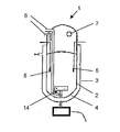
도 1은 본 발명에 따른 발효장치 용기,1 is a fermentation apparatus container according to the present invention,
도 2는 본 발명에 따른 발효장치 용기 가열장치가 장착된 뷰포트의 단면도,2 is a cross-sectional view of a viewport equipped with a fermentor vessel heating apparatus according to the present invention;
도 3은 본 발명의 발효장치 용기의 하단 부분의 단면도,3 is a cross-sectional view of the lower portion of the fermentor vessel of the present invention,
도 4는 본 발명에 따른 발효장치 용기에 설치된 입구의 단면도,Figure 4 is a cross-sectional view of the inlet installed in the fermentation apparatus container according to the present invention,
도 5는 본 발명에 따른 입구 밸브의 상단도, 그리고5 is a top view of an inlet valve according to the invention, and
도 6은 하나 이상의 발효 용기를 포함하는 본 발명의 발효장치 시스템6 is a fermentor system of the present invention comprising one or more fermentation vessels.
을 나타낸다.Indicates.
도 1에 외벽(2)을 포함하는 생물기술 공정 위한 발효장치 용기(1)가 도시된다. 용기(1)의 하부 부분에는 제 2의 벽(3)이 추가로 제공되며, 이로써 하부 부분은 이중 재킷 벽을 가지게 된다. 용기(1) 안의 육즙을 가열하기 위한 가열 매체가 중간 공간(4)을 통해 이어질 수 있다. 또한, 온도 및 압력 같은 관련된 파라미터들을 측정하기 위한 분석용 프로브(5)가 용기(1) 내부에 제공된다.1, a
용기(1)의 상부 부분에는 2개의 입구 포트(6)가 배치되고, 이것을 통해 기체나 액체가 용기(1) 쪽으로 흐를 수 있으며, 이것은 하기 설명되는 스위치 밸브까지 연결된다. 더욱이, 상부 부분에는 뷰포트(7)가 제공되는데, 이것을 사용하여 육즙과 외부 대기가 접촉하게 되는 문제 없이 용기(1) 내부의 과정을 시각적으로 점검하는 것이 가능하다. 뷰포트(7)는 도 2에 상세히 도시되는데, 이것은 유리 부분을 가진 투명 부재(8)와 격리 테두리, 예를 들어 밀봉된 이중 글레이즈 유리와 PVC-U-프레임을 포함한다. 또는 달리, 플라스틱, 또는 붕규산 유리, 석영, 소다석회-실리카 유리, 또는 강화유리와 같은 유리 이외의 다른 제재가 사용될 수도 있다.In the upper part of the
공정 동안 용기(1) 내부의 온도 증가로 인해 투명 부재(8) 상에 습기가 응축될 가능성이 있다. 이 응축물은 사용자가 투명 부재(8)를 통해 보는 것을 방해한다. 이 바람직한 구체예에서, 부재(8)의 표면에서 응축물을 제거하기 위하여, 투명 부재(8)를 가열하기 위한 몇 가지 가열장치가 제공된다. 이들 가열장치는 하나를 선택하여 또는 조합하여 사용될 수 있다.During the process, there is a possibility of condensation of moisture on the
제 1 수단으로서, 뷰포트(7)에 인접한 용기(1) 외부에 가열 램프(9)가 배치되고, 이로써 투명 부재(8)가 가열 램프(9)에 의해 조사되어 전체 투명 부재(8)가 가열된다. 이 방식에서는 투명 부재(8)를 변형하는 것이 필요하지 않으며, 일반적인 뷰포트(7)가 사용될 수 있다.As a first means, a
추가의 가열장치로서, 바람직하게는 케이블(11)에 의해 전원(도시하지 않음)에 연결된 표면 가열 와이어(10)가 투명 부재(8)의 내부 표면에 제공된다. 표면의 가열 와이어(10)를 사용하여 투명 부재(8)는 소량의 가열 에너지로 효과적으로 가열될 수 있다.As a further heating device, a
더욱이, 내부 가열 와이어(12)가 투명 부재(8) 안에 통합되어 전체 투명 부재(8)가 가열된다. 내부 가열 와이어(12)도 또한 라인(13)에 의해 전원(도시하지 않음)에 연결될 수 있다. 가열 램프(9) 및 가열 와이어(10, 12)를 포함하는 가열장치로 인해, 와이퍼의 경우 필요한 기계적 피드-스루와 흔히 오염의 원인이 되는 이것의 밀봉를 제공할 필요 없이, 투명 부재(8)의 내부 표면에서 응축물을 확실히 제거하는 것이 가능하다. Moreover, the
도 3에 본 발명의 제 2 양태가 상세히 묘사된다. 발효장치 용기(1)의 하단 부분에 교반 요소(14)가 배치된다. 이것은 교반장치 샤프트(16) 상에 장착된 교반 날개(15)를 포함한다. 교반장치 샤프트(16)의 하단부에 제 1 자기 요소(17)가 제공된다. 용기(1)의 외벽(2)에는 하단 부분에 홈(18)이 있고, 여기서 환상 벽(19)이 용기(1) 쪽으로 돌출하여 있다. 제 1 자기 요소(17)는 환상으로 형성되어 환상 벽(19)을 둘러싸고 있고, 따라서 홈(18)에 인접하여 배치된다. 홈(18)의 내부에는 제 2 자기 요소(20)가 배치되어 구동 샤프트(21) 상에 장착되며, 구동 샤프트(21)는 구동 샤프트(21)를 회전 구동시키는 모터(도시하지 않음)에 연결된다. 더욱이, 교반장치 샤프트(16)와 구동 샤프트(21)는 모두 공통 회전축을 따라 연장하여 배치된다.In figure 3 a second aspect of the invention is depicted in detail. In the lower part of the
구동 샤프트(21)와 교반장치 샤프트(16) 사이의 비-양성 연결이 자기력을 통한 자기 요소들(17, 20)의 커플링에 의해 달성된다. 이로써, 기계적 피드-스루 없이 교반 요소(14)의 회전 구동이 가능해지고, 이것은 용기 벽을 통과하는 샤프트에 의한 기계적 커플링이 사용되었던 선행기술에 비해 발효장치 용기(1)의 오염 위험을 매우 감소시킨다. 자기 커플링은 용기(1) 내부의 교반 요소(14)와 용기(1) 외부의 구동 수단의 완전한 분리를 허용한다. Non-positive connection between the
본 발명의 제 3 양태가 도 4에 도시되는데, 이것은 용기(1)에 기체 또는 액체를 도입하거나 용기(1)로부터 추출하기 위한 입구(6)를 도시한다. 입구(6)는 기체 또는 액체 공급장치(도시하지 않음)에 이르는 연결관을 포함하며, 연결관은 제 1 축(23)을 따라 연장되어 한 단부에서 용기(1)에 연결된 제 1 구역(22)을 포함한다. 제 1 구역(22)은 제 2 구역(24)까지 이어지고, 제 2 구역(24)은 제 2 축(25)을 따라 연장된다. 제 2 축(25)은 본질적으로 제 1 축(23)에 수직이다. 마지막으로, 입구(6)는 제 2 구역(24)에 연결되고 제 3 축(27)을 따라서 연장되는 제 3 구역(26)을 포함하며, 이때 제 3 축(27)은 본질적으로 제 1 축(23)에 평행하게 이격되어 있다. 바람직한 구체예에 따라서, 제 3 구역은 용기(1)까지 다시 이어지며, 이것은 구역들(22, 24, 26)에 의해 루프가 형성된다는 것을 의미한다. 또는 달리, 제 3 구역은 공급장치, 예를 들어 배양 배지 저장탱크 등에 이어질 수 있다. 더욱이, 제 2 구역(24)은 입구 밸브(28)와의 접합부를 포함한다. 입구 밸브(28)에 배지 공급원(도시하지 않음)까지 이어지는 공급관(29)이 연결된다.A third aspect of the invention is shown in FIG. 4, which shows an
구역들(22, 24, 26)에 의해 형성된 루프는, 멸균하는 동안 제재의 온도 증가로 인해 이 구역들(22, 24, 26)이 팽창할 때 화살표(30) 방향으로 구부러질 수 있다. 이런 팽창력은 배관 내 인장력을 감소시켜 균열이 형성될 위험을 줄인다. 더욱이, 이들 구역(22, 24, 26)에 의해 형성된 루프는 용기(1)와 입구 밸브(28) 사이의 입구(6)의 관의 청소를 가능하게 한다. 스팀이 제 1 구역(22)으로 들어가서 제 2 구역(24) 및 제 3 구역(26)을 지나 다시 용기(1) 쪽으로 흐를 수 있다. 따라서, 용기(1)와 입구 밸브(28) 사이의 관이 데드렉을 나타내지 않는다.The loop formed by the
도 5는 본 발명에 따른 발효장치 시스템에 사용된 스위치 밸브(31)를 상세히 도시한다. 스위치 밸브(31)는, 예를 들어 세정액 또는 스팀을 발효장치 용기 내부의 서로 다른 위치들에 분포시키기 위해서 이용된다. 스위치 밸브(31)는 멀티포트 밸브이며, 4개의 출구 스터드(33)와 4개의 구멍(34)이 있는 밸브 몸체(32)를 포함하며, 구멍(34)은 출구 스터드(33)와 연통되어 있다. 더욱이, 이 바람직한 구체예에서, 밸브 몸체(32)는 조인트 용접을 피하기 위해서 단일 피스로 형성된다. 통로관(35)이 제 1 단부(36)에서 제 2 단부(37)까지 밸브 몸체(32)를 통과해 지나가고, 구멍(34)이 통로관(35)과 교차되어 있다. 이 경우와 마찬가지로, 통로관(35)의 벽 일부가 구멍(34)과 교차하는 경우, 본 발명에서 의미하는 교차는 이미 존재하는 것이다. 제 1 단부(36)와 제 2 단부(37)는 모두 세정액 공급원(도시하지 않음)과 연통되어 있다. 따라서, 루프가 형성되고 통로관(35)이 청소될 수 있다.5 shows in detail the
밸브 요소(38)가 구멍(34)에 삽입되며, 폐쇄 위치와 개방 위치 사이에서 전환될 수 있는데, 개방 위치에서 통로관(35)이 출구 스터드(33)와 연통된다.The
통로관(35)과 구멍(34) 사이의 직접 연결은 통로관(35)을 통해 나아가는 세정액으로 멸균하는 동안 배관 내에 충분한 흐름이 도달될 수 없는 구역들을 제거한다. 구멍(34) 쪽의 통로관(35)의 개구는 밸브 요소(38)에 의해 직접 폐쇄되며, 어떤 공간도 세정제가 배관을 통해 나아갈 때 청소되지 않은 상태로 남지 않는다.The direct connection between the
이 바람직한 구체예에서, 4개의 발효장치 용기(1a, 1b, 1c 및 1b)를 포함하는 발효장치 시스템이 도 6에 도시된다. 더 나아가, 용기들(1a, 1b, 1c 및 1b)을 연결하는 수송관(39)이 제공된다. 용기들(1a, 1b, 1c 및 1b)은 하단 구역에 포트를 가지며, 이들 포트에 수송관(39)이 연결된다. 용기들(1a, 1b, 1c 및 1b) 사이의 수송관(39)에 수송 밸브(40a, 40b 및 40c)가 배치되어, 상이한 용기들(1a, 1b, 1c 및 1b) 사이의 연결의 폐쇄를 허용한다.In this preferred embodiment, a fermentor system comprising four
이 바람직한 구체예에서, 제 2 용기(1b)는 제 1 용기(1a)보다 큰 체적을 가지는데, 용기 체적은 제 1 용기(1a)에서 제 4 용기(1b) 쪽으로 증가한다. 더 나아가, 압력 입구(41a, 41b, 41c 및 41d)가 용기(1a, 1b, 1c 및 1b)에 제공된다. 압력 입구(41a, 41b, 41c 및 41d)를 통해서 압축 매체, 바람직하게는 압축공기가 용기(1a, 1b, 1c 및 1b) 중 하나에 도입되어 이 용기의 압력을 증가시킬 수 있다.In this preferred embodiment, the
바람직하게 압축공기를 압력 입구(41a)를 통해 도입함으로써 제 1 용기(1a)의 압력이 증가할 때, 수송관(39)을 사용하여 제 1 용기(1a)에서 제 2 용기(1b)로 육즙의 수송이 일어나는 것이 가능하다. 이 경우, 수송 밸브(40a)가 열리고 수송 밸브(40b)는 닫힌 상태에서 제 1 용기(1a) 내의 증가된 압력이 육즙을 밀어내어 육즙이 수송관(39)을 통해 제 2 용기(1b)로 이동된다. 동일한 방식으로, 육즙은 수송 밸브(40a 및 40c)가 닫힌 상태에서 압력 입구(41b)를 통해 제 2 용기로 압축공기를 도입함으로써 제 2 용기(1b)에서 제 3 용기(1c)로 수송될 수 있다. 이와 같이, 수송관(39)으로 인해 펌프가 생략될 수 있고, 펌프의 거품생성 효과가 제거된다. 특히, 압력 증가를 제어하여 수송관(39) 내에 단지 적은 흐름만이 있도록 할 수 있으므로, 배양 육즙 및 세포의 "평탄한" 수송을 달성하는 것이 가능하다.Preferably, when the pressure in the
본 발명의 발효장치 용기(1) 및 시스템은 세포배양, 특히 백신, 더 구체적으로는 아단위 백신 또는 분할 백신의 생산을 목적으로 바이러스를 증식시키기 위한 세포배양에서 사용될 수 있다. 더 구체적으로, 상기 바이러스는 호흡기 바이러스, 또는 인플루엔자 바이러스(유행성 균 또는 매년 발생하는 균), 또는 폴리오 바이러스, 또는 인간 면역결핍 바이러스(HIV), 인간 유두종 바이러스(HPV), 단순 헤르페스 바이러스(HSV) 또는 C-형 간염 바이러스(HCV)와 같은 성적 접촉에 의해 감염되는 질환과 관련된 바이러스들이다. 더 구체적으로, 세포는 MDCK 세포, Vero 세포, per.C.6 세포, 병아리 배아 섬유아세포(CEF) 세포, 또는 CHO 세포와 같은 동물 세포들이다.The
따라서, 본 발명은 또한 세포를 증식시키는 방법에 관한 것이며, 여기서 세포는 첨부된 청구항들에 따른 발효장치 용기 또는 발효장치 시스템에서 배양된다. 적합한 증식조건은 사용된 세포에 좌우되며, 당업자에게 잘 공지되어 있다. 본 발명에 따라서, 세포는 동물 세포일 수 있다. 바람직하게, 세포는 MDCK 세포, Vero 세포, per.C.6 세포, 병아리 배아 섬유아세포(CEF) 세포 또는 CHO 세포일 수 있다.Accordingly, the invention also relates to a method of propagating cells, wherein the cells are cultured in a fermentor vessel or fermentor system according to the appended claims. Suitable proliferation conditions depend on the cells used and are well known to those skilled in the art. According to the invention, the cell may be an animal cell. Preferably, the cells can be MDCK cells, Vero cells, per.C.6 cells, chick embryo fibroblast (CEF) cells or CHO cells.
더 이상의 양태에 따라서, 본 발명은 바이러스 백신 제조 방법을 제공하며, 이 방법은 첨부된 청구항들에 따른 발효장치 용기 또는 발효장치 시스템에서 세포를 증식시키는 단계를 포함한다. 바람직하게, 상기 방법은 바이러스를 세포를 감염시킨 다음, 이어서 바이러스의 증식을 허용하는 조건하에서 배양하는 단계를 포함한다. 마지막으로, 공지된 방법에 따라서 배양 육즙으로부터 바이러스를 수거하고, 백신 조제의 기본 재료로서 사용될 수 있는 재료로 가공한다. 백신은 아단위 백신 또는 분할 백신일 수 있다. 본 발명에 따라서, 세포는 동물 세포, 바람직하게 MDCK 세포, Vero 세포, per.C.6 세포, 병아리 배아 섬유아세포(CEF) 세포 또는 CHO 세포일 수 있다. 더 구체적으로, 상기 바이러스는 호흡기 바이러스, 또는 인플루엔자 바이러스(유행성 균 또는 매년 발생하는 균), 또는 폴리오 바이러스, 또는 인간 면역결핍 바이러스(HIV), 인간 유두종 바이러스(HPV), 단순 헤르페스 바이러스(HSV) 또는 C-형 간염 바이러스(HCV)와 같은 성적 접촉에 의해 감염되는 질환과 관련된 바이러스들이다. According to a further aspect, the present invention provides a method for producing a viral vaccine, the method comprising propagating cells in a fermentor vessel or fermentor system according to the appended claims. Preferably, the method comprises infecting the virus with a cell and then culturing under conditions that allow the virus to proliferate. Finally, the virus is harvested from the culture broth according to known methods and processed into a material that can be used as a basic material for vaccine preparation. The vaccine can be a subunit vaccine or a split vaccine. According to the invention, the cells can be animal cells, preferably MDCK cells, Vero cells, per.C.6 cells, chick embryo fibroblast (CEF) cells or CHO cells. More specifically, the virus may be a respiratory virus, or an influenza virus (pandemic or annual), or a polio virus, or human immunodeficiency virus (HIV), human papilloma virus (HPV), herpes simplex virus (HSV), or Viruses associated with diseases that are infected by sexual contact, such as hepatitis C virus (HCV).
이 방법은 바이러스의 하나 또는 몇 가지 성분 또는 바이러스를 세포 배양물로부터 분리하는 단계를 더 포함할 수 있다. 더 이상의 구체예에서, 본 방법은 세포 배양물로부터 획득된 바이러스 성분 또는 바이러스를 사용하여 백신을 조제하는 단계를 포함한다. 조제는 바이러스의 성분(들) 또는 바이러스와 제약학적으로 허용되는 담체, 보조제 및/또는 부형제를 혼합하는 단계를 포함할 수 있다. 더 나아가, 백신접종의 성질에 따라서, 바이러스는 백신 조제 전에 불활성화될 수도 있다. 바이러스 불활성화를 위한 많은 방법이 본 분야에 공지되어 있으며, 이 목적을 위해 사용될 수 있다.The method may further comprise the step of separating one or several components of the virus or virus from the cell culture. In a further embodiment, the method comprises preparing a vaccine using a viral component or virus obtained from the cell culture. The preparation may comprise mixing the component (s) or virus of the virus with a pharmaceutically acceptable carrier, adjuvant and / or excipient. Furthermore, depending on the nature of the vaccination, the virus may be inactivated prior to vaccine preparation. Many methods for virus inactivation are known in the art and can be used for this purpose.
Claims (33)
Applications Claiming Priority (2)
| Application Number | Priority Date | Filing Date | Title |
|---|---|---|---|
| EP05011607.8 | 2005-05-30 | ||
| EP05011607A EP1728852A1 (en) | 2005-05-30 | 2005-05-30 | Fermenter system for biotechnical processes |
Publications (1)
| Publication Number | Publication Date |
|---|---|
| KR20080020622A true KR20080020622A (en) | 2008-03-05 |
Family
ID=35355431
Family Applications (1)
| Application Number | Title | Priority Date | Filing Date |
|---|---|---|---|
| KR1020077029144A KR20080020622A (en) | 2005-05-30 | 2006-05-26 | Fermenter system for biotechnical processes |
Country Status (10)
| Country | Link |
|---|---|
| US (1) | US20090202589A1 (en) |
| EP (2) | EP1728852A1 (en) |
| JP (1) | JP4917597B2 (en) |
| KR (1) | KR20080020622A (en) |
| CN (1) | CN101208420A (en) |
| AU (1) | AU2006254378B2 (en) |
| BR (1) | BRPI0611014A2 (en) |
| CA (1) | CA2610306A1 (en) |
| RU (2) | RU2415912C2 (en) |
| WO (1) | WO2006128641A2 (en) |
Cited By (4)
| Publication number | Priority date | Publication date | Assignee | Title |
|---|---|---|---|---|
| KR100988701B1 (en) * | 2008-06-23 | 2010-10-18 | 한용규 | fermentation and refrigeration apparatus for lactic acid bacteria or yeast |
| KR101248541B1 (en) * | 2012-12-24 | 2013-04-03 | 김성현 | A corn fermentation device |
| WO2018048181A3 (en) * | 2016-09-06 | 2018-05-03 | 한국화학연구원 | Cell culture receptacle |
| KR20220022804A (en) * | 2020-08-19 | 2022-02-28 | 주식회사 에이치시티엠 | System for collecting virus in air |
Families Citing this family (14)
| Publication number | Priority date | Publication date | Assignee | Title |
|---|---|---|---|---|
| EP2398887A1 (en) * | 2009-02-18 | 2011-12-28 | Universiti Sains Malaysia | A solid state fermentation (ssf) system |
| KR20170053733A (en) | 2009-02-24 | 2017-05-16 | 리터 파마슈티컬즈 인코오포레이티드 | Prebiotic formulations and methods of use |
| US9550971B2 (en) * | 2009-04-14 | 2017-01-24 | Therapeutic Proteins International, LLC | Universal bioreactors and methods of use |
| IT1395068B1 (en) | 2009-08-07 | 2012-09-05 | Inalco Spa | PROCESS FOR THE PRODUCTION OF ULTRAPURI GALATTO-OLIGOSACCARIDES |
| WO2014042827A2 (en) | 2012-09-17 | 2014-03-20 | Hyclone Laboratories, Inc. | Fluid manifold system with rotatable port assembly |
| WO2015175412A1 (en) * | 2014-05-12 | 2015-11-19 | Ritter Pharmaceuticals, Inc. | Methods and systems for galactooligosac-charides manufacture |
| DE102015226022A1 (en) | 2014-12-19 | 2016-06-23 | Technische Universität Dresden | Functionally integrative bioreactor |
| CN109943462A (en) * | 2017-12-21 | 2019-06-28 | 南京蓝色气候能源技术有限公司 | A kind of anaerobic fermentation tank |
| CN108342302A (en) * | 2018-05-21 | 2018-07-31 | 芜湖裕优机械科技有限公司 | A kind of stirring-type biological fermentation tank and its method for disinfection |
| CN108504573A (en) * | 2018-06-19 | 2018-09-07 | 汇森生物设备镇江有限公司 | A kind of uniform cell culture medium automatic fermenter of sterilizing |
| CN108715810B (en) * | 2018-06-19 | 2023-05-09 | 汇森生物设备镇江有限公司 | High-performance plant cell full-automatic fermentation tank |
| CN110885725A (en) * | 2018-09-08 | 2020-03-17 | 贵州轻工职业技术学院 | Movable transparent solid-state method white spirit fermentation tank |
| RU193750U1 (en) * | 2019-01-25 | 2019-11-13 | Унибио А/С | Advanced Loop Fermenter |
| KR102255887B1 (en) * | 2019-03-19 | 2021-05-25 | (주) 텔로팜 | Plant tissue culture apparatus |
Family Cites Families (21)
| Publication number | Priority date | Publication date | Assignee | Title |
|---|---|---|---|---|
| NL301543A (en) * | 1962-12-10 | |||
| US3523331A (en) * | 1968-07-30 | 1970-08-11 | Du Pont Canada | Heated extrusion vent port monitoring window |
| US4039775A (en) * | 1975-10-01 | 1977-08-02 | Fisher Scientific Company | Uniform temperature incubator |
| US5135853A (en) * | 1983-07-22 | 1992-08-04 | Rensselaer Polytechnic Institute | Three compartment bioreactor and method of use |
| US4703010A (en) * | 1986-05-02 | 1987-10-27 | The Board Of Regents For The University Of Oklahoma | Electrolytic bioreactor assembly and method |
| US4952510A (en) * | 1987-01-02 | 1990-08-28 | Bio-North, Inc. | Apparatus for detecting and culturing microorganisms using a biphasic culture vessel |
| JPH01137964A (en) * | 1987-11-24 | 1989-05-30 | Terumo Corp | Culture vessel |
| JP2624735B2 (en) * | 1988-01-11 | 1997-06-25 | 株式会社日立製作所 | Culture tank and its cleaning method |
| DE3818776C2 (en) * | 1988-06-02 | 1994-06-30 | Maerkl Herbert | Process for culturing cells in a fermenter and performing the process of certain fermenters |
| US5043431A (en) * | 1989-09-11 | 1991-08-27 | Codon | Method and apparatus for the production of TGF-β |
| JPH0530957A (en) * | 1991-07-30 | 1993-02-09 | Ebara Corp | Apparatus for culturing |
| EP0682697A4 (en) * | 1993-01-29 | 1997-07-30 | New Brunswick Scientific Co | Method and apparatus for anchorage and suspension cell culture. |
| US5661029A (en) * | 1994-05-12 | 1997-08-26 | Biomed | Biological culture growth and observation device |
| JPH09140375A (en) * | 1995-11-24 | 1997-06-03 | Kawata Kogyo Kk | Production of malted rice and apparatus used therefor |
| US5958756A (en) * | 1996-01-26 | 1999-09-28 | Reynell; Christopher Paul | Method and apparatus for treating waste |
| JP3548761B2 (en) * | 1996-07-12 | 2004-07-28 | 株式会社東海ヒット | Transparent thermostatic culture vessel for microscope observation |
| DE19705425A1 (en) * | 1997-02-13 | 1998-08-20 | Buehler Ag | Screen wiper, especially for inspection glass fittings |
| US5977526A (en) * | 1999-03-05 | 1999-11-02 | Board Of Regents The University Of Texas | Heater for high vacuum optical view port |
| US6837613B2 (en) * | 2001-04-10 | 2005-01-04 | Levtech, Inc. | Sterile fluid pumping or mixing system and related method |
| US6555365B2 (en) * | 2000-12-07 | 2003-04-29 | Biocrystal, Ltd. | Microincubator comprising a cell culture apparatus and a transparent heater |
| JP3852109B2 (en) * | 2002-04-02 | 2006-11-29 | 栗田工業株式会社 | Methane fermentation treatment equipment |
-
2005
- 2005-05-30 EP EP05011607A patent/EP1728852A1/en not_active Withdrawn
-
2006
- 2006-05-26 AU AU2006254378A patent/AU2006254378B2/en not_active Ceased
- 2006-05-26 CA CA002610306A patent/CA2610306A1/en not_active Abandoned
- 2006-05-26 JP JP2008513989A patent/JP4917597B2/en not_active Expired - Fee Related
- 2006-05-26 CN CNA2006800189411A patent/CN101208420A/en active Pending
- 2006-05-26 US US11/915,877 patent/US20090202589A1/en not_active Abandoned
- 2006-05-26 RU RU2007149323/13A patent/RU2415912C2/en not_active IP Right Cessation
- 2006-05-26 KR KR1020077029144A patent/KR20080020622A/en not_active Application Discontinuation
- 2006-05-26 BR BRPI0611014-2A patent/BRPI0611014A2/en not_active IP Right Cessation
- 2006-05-26 WO PCT/EP2006/005033 patent/WO2006128641A2/en active Application Filing
- 2006-05-26 EP EP06753895A patent/EP1885838A2/en not_active Withdrawn
-
2010
- 2010-12-09 RU RU2010150611/10A patent/RU2010150611A/en not_active Application Discontinuation
Cited By (4)
| Publication number | Priority date | Publication date | Assignee | Title |
|---|---|---|---|---|
| KR100988701B1 (en) * | 2008-06-23 | 2010-10-18 | 한용규 | fermentation and refrigeration apparatus for lactic acid bacteria or yeast |
| KR101248541B1 (en) * | 2012-12-24 | 2013-04-03 | 김성현 | A corn fermentation device |
| WO2018048181A3 (en) * | 2016-09-06 | 2018-05-03 | 한국화학연구원 | Cell culture receptacle |
| KR20220022804A (en) * | 2020-08-19 | 2022-02-28 | 주식회사 에이치시티엠 | System for collecting virus in air |
Also Published As
| Publication number | Publication date |
|---|---|
| AU2006254378B2 (en) | 2011-11-03 |
| AU2006254378A1 (en) | 2006-12-07 |
| RU2415912C2 (en) | 2011-04-10 |
| EP1728852A1 (en) | 2006-12-06 |
| WO2006128641A2 (en) | 2006-12-07 |
| RU2007149323A (en) | 2009-07-20 |
| JP4917597B2 (en) | 2012-04-18 |
| CA2610306A1 (en) | 2006-12-07 |
| RU2010150611A (en) | 2012-06-20 |
| BRPI0611014A2 (en) | 2010-08-10 |
| JP2008541741A (en) | 2008-11-27 |
| CN101208420A (en) | 2008-06-25 |
| US20090202589A1 (en) | 2009-08-13 |
| WO2006128641A3 (en) | 2007-04-19 |
| EP1885838A2 (en) | 2008-02-13 |
Similar Documents
| Publication | Publication Date | Title |
|---|---|---|
| KR20080020622A (en) | Fermenter system for biotechnical processes | |
| EP2167637B1 (en) | Bioreactor probe connection system | |
| JP5281483B2 (en) | Stirred tank bioreactor | |
| US8822208B2 (en) | Bioreactor and method | |
| US20180362909A1 (en) | Method for Using a Disposable Bioreactor | |
| US20110201100A1 (en) | Single use cell culture bioreactor manifold system | |
| JP5893051B2 (en) | Alternating pneumatic membrane cell separation system | |
| MXPA06011837A (en) | Stirred-tank reactor system. | |
| KR20150056548A (en) | Disposable bottle reactor tank | |
| JPH10505503A (en) | A new sampling device for bioprocessing analysis | |
| EP2853584B1 (en) | Single-use bioreactor with baffles and a process for manufacturing and operating the same | |
| JP2004536567A (en) | Multi-sample fermenter and method of using same | |
| JP2004536567A5 (en) | ||
| EP3183334A1 (en) | Systems and methods for aseptic sampling | |
| CN208395171U (en) | A kind of biopharmaceutical liquids material transmitting isolating and protecting device | |
| US20120250450A1 (en) | External mixing device | |
| Oosterhuis et al. | Design, Applications, and Development of Single‐Use Bioreactors | |
| US4318992A (en) | Fermenter | |
| JPH0286762A (en) | Air scattering system | |
| KR102334488B1 (en) | Apparatus for culturing large-scale seed of microalgae | |
| CN220201924U (en) | Device for continuous sampling in bioreactor culture process | |
| KR102342765B1 (en) | Plant cell culture apparatus | |
| CN209128457U (en) | A kind of duct type attached cell culture domesticating device | |
| US20140038276A1 (en) | Reaction vessel | |
| Allman | Bioreactors: design, operation, and applications |
Legal Events
| Date | Code | Title | Description |
|---|---|---|---|
| A201 | Request for examination | ||
| E601 | Decision to refuse application |