RU2381038C2 - Multichannel coordinated infusion set - Google Patents
Multichannel coordinated infusion set Download PDFInfo
- Publication number
- RU2381038C2 RU2381038C2 RU2007114267/14A RU2007114267A RU2381038C2 RU 2381038 C2 RU2381038 C2 RU 2381038C2 RU 2007114267/14 A RU2007114267/14 A RU 2007114267/14A RU 2007114267 A RU2007114267 A RU 2007114267A RU 2381038 C2 RU2381038 C2 RU 2381038C2
- Authority
- RU
- Russia
- Prior art keywords
- infusion
- infusate
- syringe
- remaining
- volume
- Prior art date
Links
Images


Classifications
-
- A—HUMAN NECESSITIES
- A61—MEDICAL OR VETERINARY SCIENCE; HYGIENE
- A61M—DEVICES FOR INTRODUCING MEDIA INTO, OR ONTO, THE BODY; DEVICES FOR TRANSDUCING BODY MEDIA OR FOR TAKING MEDIA FROM THE BODY; DEVICES FOR PRODUCING OR ENDING SLEEP OR STUPOR
- A61M1/00—Suction or pumping devices for medical purposes; Devices for carrying-off, for treatment of, or for carrying-over, body-liquids; Drainage systems
- A61M1/36—Other treatment of blood in a by-pass of the natural circulatory system, e.g. temperature adaptation, irradiation ; Extra-corporeal blood circuits
- A61M1/3687—Chemical treatment
-
- A—HUMAN NECESSITIES
- A61—MEDICAL OR VETERINARY SCIENCE; HYGIENE
- A61M—DEVICES FOR INTRODUCING MEDIA INTO, OR ONTO, THE BODY; DEVICES FOR TRANSDUCING BODY MEDIA OR FOR TAKING MEDIA FROM THE BODY; DEVICES FOR PRODUCING OR ENDING SLEEP OR STUPOR
- A61M5/00—Devices for bringing media into the body in a subcutaneous, intra-vascular or intramuscular way; Accessories therefor, e.g. filling or cleaning devices, arm-rests
- A61M5/14—Infusion devices, e.g. infusing by gravity; Blood infusion; Accessories therefor
- A61M5/168—Means for controlling media flow to the body or for metering media to the body, e.g. drip meters, counters ; Monitoring media flow to the body
- A61M5/16886—Means for controlling media flow to the body or for metering media to the body, e.g. drip meters, counters ; Monitoring media flow to the body for measuring fluid flow rate, i.e. flowmeters
- A61M5/16895—Means for controlling media flow to the body or for metering media to the body, e.g. drip meters, counters ; Monitoring media flow to the body for measuring fluid flow rate, i.e. flowmeters by monitoring weight change, e.g. of infusion container
-
- A—HUMAN NECESSITIES
- A61—MEDICAL OR VETERINARY SCIENCE; HYGIENE
- A61M—DEVICES FOR INTRODUCING MEDIA INTO, OR ONTO, THE BODY; DEVICES FOR TRANSDUCING BODY MEDIA OR FOR TAKING MEDIA FROM THE BODY; DEVICES FOR PRODUCING OR ENDING SLEEP OR STUPOR
- A61M1/00—Suction or pumping devices for medical purposes; Devices for carrying-off, for treatment of, or for carrying-over, body-liquids; Drainage systems
- A61M1/14—Dialysis systems; Artificial kidneys; Blood oxygenators ; Reciprocating systems for treatment of body fluids, e.g. single needle systems for hemofiltration or pheresis
-
- A—HUMAN NECESSITIES
- A61—MEDICAL OR VETERINARY SCIENCE; HYGIENE
- A61M—DEVICES FOR INTRODUCING MEDIA INTO, OR ONTO, THE BODY; DEVICES FOR TRANSDUCING BODY MEDIA OR FOR TAKING MEDIA FROM THE BODY; DEVICES FOR PRODUCING OR ENDING SLEEP OR STUPOR
- A61M1/00—Suction or pumping devices for medical purposes; Devices for carrying-off, for treatment of, or for carrying-over, body-liquids; Drainage systems
- A61M1/34—Filtering material out of the blood by passing it through a membrane, i.e. hemofiltration or diafiltration
- A61M1/342—Adding solutions to the blood, e.g. substitution solutions
- A61M1/3441—Substitution rate control as a function of the ultrafiltration rate
- A61M1/3451—Substitution rate control as a function of the ultrafiltration rate the difference in weight between both ultra-filtrate and substitution reservoir being used as control signal
-
- A—HUMAN NECESSITIES
- A61—MEDICAL OR VETERINARY SCIENCE; HYGIENE
- A61M—DEVICES FOR INTRODUCING MEDIA INTO, OR ONTO, THE BODY; DEVICES FOR TRANSDUCING BODY MEDIA OR FOR TAKING MEDIA FROM THE BODY; DEVICES FOR PRODUCING OR ENDING SLEEP OR STUPOR
- A61M5/00—Devices for bringing media into the body in a subcutaneous, intra-vascular or intramuscular way; Accessories therefor, e.g. filling or cleaning devices, arm-rests
- A61M5/14—Infusion devices, e.g. infusing by gravity; Blood infusion; Accessories therefor
- A61M5/142—Pressure infusion, e.g. using pumps
- A61M5/14212—Pumping with an aspiration and an expulsion action
- A61M5/14232—Roller pumps
-
- A—HUMAN NECESSITIES
- A61—MEDICAL OR VETERINARY SCIENCE; HYGIENE
- A61M—DEVICES FOR INTRODUCING MEDIA INTO, OR ONTO, THE BODY; DEVICES FOR TRANSDUCING BODY MEDIA OR FOR TAKING MEDIA FROM THE BODY; DEVICES FOR PRODUCING OR ENDING SLEEP OR STUPOR
- A61M5/00—Devices for bringing media into the body in a subcutaneous, intra-vascular or intramuscular way; Accessories therefor, e.g. filling or cleaning devices, arm-rests
- A61M5/14—Infusion devices, e.g. infusing by gravity; Blood infusion; Accessories therefor
- A61M5/142—Pressure infusion, e.g. using pumps
- A61M5/145—Pressure infusion, e.g. using pumps using pressurised reservoirs, e.g. pressurised by means of pistons
- A61M5/1452—Pressure infusion, e.g. using pumps using pressurised reservoirs, e.g. pressurised by means of pistons pressurised by means of pistons
-
- A—HUMAN NECESSITIES
- A61—MEDICAL OR VETERINARY SCIENCE; HYGIENE
- A61M—DEVICES FOR INTRODUCING MEDIA INTO, OR ONTO, THE BODY; DEVICES FOR TRANSDUCING BODY MEDIA OR FOR TAKING MEDIA FROM THE BODY; DEVICES FOR PRODUCING OR ENDING SLEEP OR STUPOR
- A61M5/00—Devices for bringing media into the body in a subcutaneous, intra-vascular or intramuscular way; Accessories therefor, e.g. filling or cleaning devices, arm-rests
- A61M5/14—Infusion devices, e.g. infusing by gravity; Blood infusion; Accessories therefor
- A61M5/168—Means for controlling media flow to the body or for metering media to the body, e.g. drip meters, counters ; Monitoring media flow to the body
- A61M5/16886—Means for controlling media flow to the body or for metering media to the body, e.g. drip meters, counters ; Monitoring media flow to the body for measuring fluid flow rate, i.e. flowmeters
-
- A—HUMAN NECESSITIES
- A61—MEDICAL OR VETERINARY SCIENCE; HYGIENE
- A61M—DEVICES FOR INTRODUCING MEDIA INTO, OR ONTO, THE BODY; DEVICES FOR TRANSDUCING BODY MEDIA OR FOR TAKING MEDIA FROM THE BODY; DEVICES FOR PRODUCING OR ENDING SLEEP OR STUPOR
- A61M5/00—Devices for bringing media into the body in a subcutaneous, intra-vascular or intramuscular way; Accessories therefor, e.g. filling or cleaning devices, arm-rests
- A61M5/14—Infusion devices, e.g. infusing by gravity; Blood infusion; Accessories therefor
- A61M5/168—Means for controlling media flow to the body or for metering media to the body, e.g. drip meters, counters ; Monitoring media flow to the body
- A61M5/172—Means for controlling media flow to the body or for metering media to the body, e.g. drip meters, counters ; Monitoring media flow to the body electrical or electronic
-
- Y—GENERAL TAGGING OF NEW TECHNOLOGICAL DEVELOPMENTS; GENERAL TAGGING OF CROSS-SECTIONAL TECHNOLOGIES SPANNING OVER SEVERAL SECTIONS OF THE IPC; TECHNICAL SUBJECTS COVERED BY FORMER USPC CROSS-REFERENCE ART COLLECTIONS [XRACs] AND DIGESTS
- Y02—TECHNOLOGIES OR APPLICATIONS FOR MITIGATION OR ADAPTATION AGAINST CLIMATE CHANGE
- Y02A—TECHNOLOGIES FOR ADAPTATION TO CLIMATE CHANGE
- Y02A90/00—Technologies having an indirect contribution to adaptation to climate change
- Y02A90/10—Information and communication technologies [ICT] supporting adaptation to climate change, e.g. for weather forecasting or climate simulation
Abstract
Description
Область техники, к которой относится изобретениеFIELD OF THE INVENTION
Настоящее изобретение, в общем, относится к отслеживанию количества медицинской жидкости, подаваемой насосом, и более конкретно, к точному отслеживанию количества остающейся медицинской жидкости, и расчету скорости потока для полной ее подачи в течение заданного периода времени.The present invention generally relates to tracking the amount of medical fluid supplied by a pump, and more particularly, to accurately tracking the amount of remaining medical fluid, and calculating a flow rate for full flow thereof over a given period of time.
Уровень техникиState of the art
Известны инфузионные системы, которые содержат множество насосных модулей для инфузии, которые включают в себя систему насосов для инфузии с центральным управлением, в которой насосные модули и модули отслеживания избирательно присоединяют к центральному модулю управления. Центральный модуль управления управляет внутренними установками и программированием установленных модулей и принимает и отображает информацию, получаемую от них. Каждый модуль может быть отсоединен от центрального модуля управления.Infusion systems are known that comprise a plurality of infusion pump modules, which include a centrally controlled infusion pump system in which pump modules and tracking modules are selectively coupled to a central control module. The central control module controls the internal settings and programming of the installed modules and receives and displays the information received from them. Each module can be disconnected from the central control module.
Из-за неточностей инфузионной системы точность ее работы может составлять плюс - минус 5% или больше при работе в течение длительных периодов и под действием других факторов, таких как перелив пакетов для внутривенного (IV, ВВ) вливания или перерывы подачи потока, требуемый объем лекарственного средства может не быть влит в течение заданного периода времени, и инфузия может опережать график или отставать от графика, в некоторых случаях на час или два. Работник клиники, то есть специалист, квалифицированный в клинической практике, медицине, психиатрии или психологии, должен затем вручную увеличивать или уменьшать скорость потока для компенсации этих факторов, как только проблема будет распознана. Перерывы в приеме медикамента могут привести к неудобствам и задержкам для пациента и клинических работников, а также потенциально могут отрицательно влиять на терапевтическую эффективность лечения. Токсичность лекарства также может стать проблемой, в случае когда скорость инфузии будет повышена в конце вливания, с тем чтобы обеспечить окончание процедуры в заданное время.Due to inaccuracies in the infusion system, the accuracy of its operation can be plus or
Один из подходов, которые используют клинические врачи для решения указанной выше проблемы, состоит во взвешивании ВВ пакета для определения точного объема пакета. Такой подход является не полностью удовлетворительным, поскольку пакет должен быть тщательно взвешен в аптеке, и вес пустого пакета должен быть вычтен из общего веса пакета. Различия в точности шкалы и коррекция удельного веса (плотности) раствора (которая обычно неизвестна) приводят к дополнительным неточностям. Обычно работник клиники устанавливает скорость потока при вливании на основе полученного объема раствора. Этот способ не позволяет выполнить точную коррекцию скорости потока из-за перерывов подачи потока после начала инфузии и, таким образом, может не обеспечить подачу медицинского средства для инфузии в тело пациента в течение требуемого периода времени. После окончания инфузии, во время которой происходили перерывы, у работника клиники часто остается значительный объем остаточного медикамента в ВВ пакете или в трубках, которые требуется промыть или выбросить. Если остаточный объем будет выброшен, пациент может не получить полную дозу, назначенную клиническим работником, в результате чего снижается эффект медикамента.One approach that clinicians use to solve the above problem is to weigh the BB packet to determine the exact volume of the packet. This approach is not entirely satisfactory because the package must be carefully weighed at the pharmacy and the weight of the empty package must be subtracted from the total weight of the package. Differences in the accuracy of the scale and the correction of the specific gravity (density) of the solution (which is usually unknown) lead to additional inaccuracies. Typically, a clinic worker sets the flow rate for infusion based on the volume of solution obtained. This method does not allow for accurate correction of the flow rate due to interruptions in the flow of the stream after the start of the infusion and, thus, may not ensure the delivery of the medication for infusion into the patient’s body for the required period of time. After the end of the infusion, during which interruptions took place, the clinic employee often has a significant amount of residual medication in the BB bag or in tubes that need to be flushed or discarded. If the residual volume is ejected, the patient may not receive the full dose prescribed by the clinical worker, as a result of which the effect of the medication is reduced.
В связи с этим была идентифицирована постоянная потребность в создании системы медицинской инфузии, которая позволила бы точно вливать медикамент в течение заданных периодов времени.In this regard, the constant need was identified for the creation of a medical infusion system that would allow the medication to be precisely infused over predetermined time periods.
Сущность изобретенияSUMMARY OF THE INVENTION
Вкратце и в общих чертах, настоящее изобретение направлено на инфузионную систему, которая подает первый инфузат, предпочтительно медикамент, в венозный катетер, и второй инфузат, предпочтительно нейтральный раствор-носитель, в венозный катетер пациента. Инфузионная система также включает в себя измерительное устройство, которое определяет количество неподанного первого инфузата, остающегося в системе. Кроме того, инфузионная система включает в себя систему управления, которая управляет подачей первого инфузата и которая позволяет вводить заданный объем подаваемого первого инфузата в период времени, в течение которого должно произойти вливание объема первого инфузата. Система управления также соединена с первым и вторым устройствами подачи и устройством измерения для определения оптимальной скорости потока вливания первого инфузата на основе заданного первого объема инфузата, заданного периода времени инфузии и определенного количества неподанного первого инфузата, остающегося в системе, и управления первым устройством подачи для подачи первого инфузата с оптимальной скоростью потока инфузии.Briefly and broadly, the present invention is directed to an infusion system that delivers a first infusion, preferably a medicament, to a venous catheter, and a second infusion, preferably a neutral carrier solution, to a patient's venous catheter. The infusion system also includes a measuring device that determines the amount of non-delivered first infusate remaining in the system. In addition, the infusion system includes a control system that controls the flow of the first infusate and which allows you to enter a predetermined volume of the supplied first infusate in the period of time during which the infusion of the volume of the first infusate should occur. The control system is also connected to the first and second feeding devices and a measuring device for determining an optimal infusion flow rate of the first infusate based on a predetermined first infusion volume, a predetermined infusion time period and a certain amount of unsuitable first infusate remaining in the system, and controlling the first infeed device first infusion with optimal infusion flow rate.
В соответствии с другим аспектом изобретения дополнительно предложена инфузионная система, содержащая первое устройство подачи, которое подает инфузионный ультрафильтрат в гемофильтр, и первое устройство измерения, которое определяет количество инфузионного ультрафильтрата в инфузионной системе. Инфузионная система также включает в себя второе устройство подачи, которое принимает извлеченный из тела пациента ультрафильтрат из гемофильтра, и второе устройство измерения, которое определяет количество извлеченного ультрафильтрата в инфузионной системе. Кроме того, инфузионная система включает в себя систему управления, которая связана с первым и вторым устройствами подачи и первым и вторым модулями измерения, для определения оптимальной скорости потока в гемофильтр и из него на основе определенных количеств инфузионного ультрафильтрата и удаленного ультрафильтрата в инфузионной системе, и заданной желательной разности давлений между вливаемым и удаляемым ультрафильтратами, и для управления первым и вторым модулями подачи, соответственно.In accordance with another aspect of the invention, there is further provided an infusion system comprising a first infusion device that supplies the infusion ultrafiltrate to the hemofilter and a first measuring device that determines the amount of infusion ultrafiltrate in the infusion system. The infusion system also includes a second feeding device that receives the ultrafiltrate removed from the patient’s body from the hemofilter, and a second measuring device that determines the amount of ultrafiltrate recovered in the infusion system. In addition, the infusion system includes a control system that is connected to the first and second feeding devices and the first and second measurement modules to determine the optimal flow rate to and from the hemofilter based on certain amounts of the infusion ultrafiltrate and the removed ultrafiltrate in the infusion system, and the desired desired pressure difference between the infused and removed ultrafiltrates, and for controlling the first and second feed modules, respectively.
В других аспектах изобретения предложен способ инфузии первого инфузата в тело пациента. Работник клиники или сама система определяют общий объем первого инфузата, который должен быть подан в тело пациента. Работник клиники затем устанавливает период времени, в течение которого требуется влить общий объем первого инфузата, например двадцать четыре часа. Датчик положения шприцевого насоса или датчик веса насоса большого объема детектирует остающееся количество первого инфузата, который должен быть влит. Система управления постоянно рассчитывает остающееся время заданного периода. Насос большого объема (LVP, НБО) подает второй инфузат в линию инфузии пациента, в то время как шприцевой насос или комбинация НБО и датчика веса подает первый инфузат в венозный катетер. Система управления, предпочтительно, постоянно и автоматически регулирует скорость потока инфузии на основе остаточного количества первого инфузата, который должен быть влит, и остающегося времени заданного периода времени. Этапы детектирования, расчета, подачи, инфузии и регулирования, предпочтительно, повторяют до тех пор, пока не будет влит общий объем первого инфузата.In other aspects of the invention, there is provided a method for infusing a first infusion into a patient's body. The clinic employee or the system itself determines the total volume of the first infusate, which must be fed into the patient’s body. The clinic worker then sets a period of time during which it is necessary to infuse the total volume of the first infusion, for example twenty-four hours. A syringe pump position sensor or a large volume pump weight sensor detects the remaining amount of the first infusate to be infused. The control system constantly calculates the remaining time of a given period. A large volume pump (LVP, NBO) delivers a second infusion into the patient's infusion line, while a syringe pump or a combination of NBO and a weight sensor delivers the first infusion into the venous catheter. The control system preferably continuously and automatically adjusts the infusion flow rate based on the residual amount of the first infusion to be infused and the remaining time of a predetermined time period. The steps of detecting, calculating, dispensing, infusion and regulation are preferably repeated until the total volume of the first infusion is poured.
В других аспектах предложен способ инфузии ультрафильтрата в тело пациента, содержащий этапы подачи инфузионного ультрафильтрата в гемофильтр, измерение количества инфузионного ультрафильтрата в инфузионной системе, получение ультрафильтрата, извлеченного из тела пациента, из гемофильтра, измерение количества извлеченного ультрафильтрата в инфузионной системе и регулирование скорости потока на этапах подачи и приема на основе измеренных количеств инфузионного и извлеченного ультрафильтрата в инфузионной системе и заданной требуемой разности давлений между инфузионным и извлеченным ультрафильтратами.In other aspects, there is provided a method for infusing an ultrafiltrate into a patient’s body, comprising the steps of supplying an infusion ultrafiltrate to a hemofilter, measuring the amount of infusion ultrafiltrate in the infusion system, obtaining an ultrafiltrate recovered from the patient’s body from the hemofilter, measuring the amount of ultrafiltrate recovered in the infusion system, and adjusting the flow rate to the stages of supply and reception based on the measured quantities of infusion and recovered ultrafiltrate in the infusion system and a given requirement my pressure difference between infusion and removed ultrafiltrate.
Новые свойства настоящего изобретения, а также само изобретение как в отношении его структуры, так и его работы лучше всего будут понятны из следующих чертежей, которые следует рассматривать совместно с прилагаемым описанием.The new features of the present invention, as well as the invention itself, both in terms of its structure and its operation, will be best understood from the following drawings, which should be read in conjunction with the attached description.
Краткое описание чертежейBrief Description of the Drawings
На фиг.1 показана схема многоканальной координированной инфузионной системы в соответствии с аспектами настоящего изобретения, представляющая медицинские жидкости, подаваемые из двух разных источников жидкости, приемник (пакет для жидкости) и шприц, накачиваемый в общую линию ВВ подачи для инфузии в тело пациента, с использованием двух насосов для инфузии, под общим управлением модуля программирования;Figure 1 shows a diagram of a multi-channel coordinated infusion system in accordance with aspects of the present invention, representing medical fluids supplied from two different fluid sources, a receiver (fluid bag) and a syringe pumped into a common supply line BB for infusion into a patient’s body, with the use of two infusion pumps, under the general control of a programming module;
на фиг.2 показан вид с увеличением модуля программирования, представленного на фиг.1;figure 2 shows a view with an increase in the programming module shown in figure 1;
на фиг.3 показан график, представляющий зависимость скорости потока от времени во время сеанса инфузии;figure 3 shows a graph representing the dependence of the flow rate on time during the infusion session;
на фиг.4А-4V показаны экраны интерфейса пользователя, представляемые модулем программирования на фиг.1, когда выполняется программирование инфузии из двух разных источников, представленных на фиг.1;4A-4V show the user interface screens represented by the programming module of FIG. 1 when infusion programming is performed from two different sources shown in FIG. 1;
на фиг.5 показана блок-схема последовательности операций способа инфузии медикаментов в тело пациента в соответствии с инфузионной системой на фиг.1-4;figure 5 shows a block diagram of a sequence of operations of the method of infusion of drugs into the patient's body in accordance with the infusion system in figure 1-4;
на фиг.6 показана схема другого варианта выполнения многоканальной скоординированной инфузионной системы в соответствии с аспектами настоящего изобретения, представляющая медицинские жидкости, расположенные в двух разных источниках жидкости, и насос большого объема для инфузии, имеющий датчик веса;6 is a diagram of another embodiment of a multi-channel coordinated infusion system in accordance with aspects of the present invention, representing medical fluids located in two different fluid sources and a large infusion pump having a weight sensor;
жидкости накачивают в общий венозный катетер для инфузии в тело пациента под общим управлением модуля программирования;fluids are pumped into a common venous catheter for infusion into the patient’s body under the general control of a programming module;
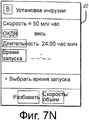
на фиг.7А-7U показаны экраны интерфейса пользователя, представляемые модулем программирования на фиг.6, когда выполняется программирование инфузии из двух разных источников, показанных на фиг.6;on figa-7U shows the user interface screens presented by the programming module in Fig.6, when programming is carried out infusion from two different sources shown in Fig.6;
на фиг.8 показана схема дополнительного варианта выполнения многоканальной скоординированной инфузионной системы в соответствии с аспектами настоящего изобретения, представляющая удаление и замену ультрафильтратов через комбинацию насоса большого объема для инфузии - датчика веса, для инфузии в тело пациента под общим управлением модуля программирования;on Fig shows a diagram of an additional embodiment of a multi-channel coordinated infusion system in accordance with aspects of the present invention, representing the removal and replacement of ultrafiltrates through a combination of a large volume pump for infusion - weight sensor, for infusion into the patient's body under the general control of a programming module;
на фиг.9 показана блок-схема - последовательность операций способа удаления и замены ультрафильтратов в соответствии с инфузионной системой на фиг.8.in Fig.9 shows a flowchart - a sequence of operations of a method of removing and replacing ultrafiltrates in accordance with the infusion system in Fig.8.
Подробное описание изобретенияDETAILED DESCRIPTION OF THE INVENTION
Рассмотрим более подробно чертежи, на которых одинаковыми ссылочными позициями обозначены аналогичные или соответствующие элементы на нескольких видах, многоканальная координированная инфузионная система в соответствии с изобретением вливает заданный объем медикамента в течение определенного заданного периода, например 1000 мл химиотерапевтического агента в течение 24 часов.Let us consider in more detail the drawings, in which the same reference numbers indicate similar or corresponding elements in several forms, the multichannel coordinated infusion system in accordance with the invention infuses a predetermined volume of medication over a given predetermined period, for example, 1000 ml of a chemotherapeutic agent within 24 hours.
Настоящее изобретение поясняется на примере, в котором в тело пациента выполняют вливание химиотерапевтического медикамента или другого медикамента. Следует понимать, что такой пример предназначен только для иллюстрации.The present invention is illustrated by an example in which an infusion of a chemotherapeutic drug or other drug is infused into a patient’s body. It should be understood that such an example is for illustration only.
Обычно химиотерапевтический медикамент вливают в течение множества сеансов, продолжающихся много дней. Из-за неточностей некоторых инфузионных систем или перерывов в подаче при вливании вливание может опережать график или отставать от него на много часов к концу сеанса инфузии. Настоящее изобретение решает эту проблему, и иллюстративные варианты его выполнения представлены ниже. В одном варианте выполнения устройства точной передачи жидкости, например, используется датчик веса в комбинации с инфузионным насосом большого объема (НБО), где устройство передачи жидкости управляется с помощью модуля управления с применением микропроцессора.Typically, a chemotherapeutic drug is infused over multiple sessions over many days. Due to inaccuracies in some infusion systems or interruptions in infusion flow, the infusion may be ahead of the schedule or be behind it by many hours by the end of the infusion session. The present invention solves this problem, and illustrative options for its implementation are presented below. In one embodiment of an accurate fluid transfer device, for example, a weight sensor is used in combination with a large volume infusion pump (NBO), where the fluid transfer device is controlled by a microprocessor-based control module.
Шприцевые насосы обычно состоят из цилиндра, в котором содержится жидкость, которую выталкивают путем перемещения поршня. Поршень обычно перемещается внутри цилиндра с помощью механизма привода, который включает в себя двигатель, соединенный через зубчатое колесо или колеса с головкой привода, для обеспечения относительно постоянного потока, не содержащего импульсы. В соответствии с аспектом настоящего изобретения предложено средство точного вливания заданного объема жидкости в течение заданного периода времени. Вместо программирования определенной скорости потока работник клиники может запрограммировать определенный объем, который должен быть влит в течение определенного периода времени, и система автоматически регулирует скорость потока в пределах установленных параметров на основе остающегося объема, который должен быть влит, и остающегося периода инфузии. Система также адаптируется к любым изменениям при запуске и остановке системы ввиду обстоятельств, которые могут возникнуть во время инфузии, таких как закупорка или наличие воздуха в инфузионной линии или по некоторым другим причинам, когда инфузия должна быть мгновенно остановлена.Syringe pumps typically consist of a cylinder containing fluid that is ejected by moving the piston. The piston is typically moved inside the cylinder by a drive mechanism that includes an engine coupled through a gear or wheels to the drive head to provide a relatively constant pulse-free flow. In accordance with an aspect of the present invention, there is provided a means for accurately infusing a predetermined volume of liquid over a predetermined period of time. Instead of programming a specific flow rate, the clinic worker can program a specific volume that must be poured over a certain period of time, and the system automatically adjusts the flow rate within the set parameters based on the remaining volume that must be poured and the remaining infusion period. The system also adapts to any changes when starting and stopping the system due to circumstances that may occur during infusion, such as blockage or air in the infusion line or for some other reason when the infusion should be stopped immediately.
Обычно растворы медикаментов поставляют в концентрированной форме и их требуется разбавить перед инфузией в тело пациента. Поскольку шприцы обычно содержат относительно малые объемы жидкости по сравнению с пакетами внутривенных капельниц, при этом многие медикаменты, поставляемые внутри шприцов, поставляют в концентрированной форме, их требуется разбавлять во время приема. Настоящее изобретение позволяет непрерывно разбавлять концентрированные медикаменты внутри шприцов, используя нейтральный раствор - носитель, такой как нормальный физиологический раствор, подаваемый через насос большого объема (НБО).Usually, drug solutions are supplied in concentrated form and must be diluted before infusion into the patient's body. Since syringes usually contain relatively small volumes of fluid compared to intravenous dropper bags, and many of the medications delivered inside the syringes are delivered in concentrated form, they must be diluted during administration. The present invention allows continuous dilution of concentrated medicines inside syringes using a neutral carrier solution, such as normal saline, delivered through a large volume pump (NBO).
На фиг.1 показан вид многоканальной скоординированной инфузионной системы 10 в соответствии с одним вариантом выполнения изобретения. Многоканальная скоординированная инфузионная система 10 включает в себя программируемую систему ухода за пациентом, аналогичную раскрытой в патенте США № 5,713,856 автора Eggers, выданном 3 февраля 1998 г., который приведен здесь в качестве ссылочного материала. Программируемая система ухода за пациентом включает в себя модуль (PCU, МУП) 12 ухода за пациентом в комбинации, по меньшей мере, с двумя функциональными модулями 14 и 16. МУП 12 включает в себя систему управления и, в общем, выполняет четыре функции в системе ухода за пациентом: он обеспечивает физическое соединение системы со структурами, такими как стойки для ВВ установок и поручни кровати; он подает питание в систему; он обеспечивает интерфейс между системой и внешними устройствами, за исключением определенной информации; обеспечивает большую часть интерфейса пользователя с системой.Figure 1 shows a view of a multi-channel coordinated
На фиг.2 показан вид с увеличением МУП 12, показанного на фиг.1. МУП 12 включает в себя информационный дисплей 18, который может быть дисплеем любого типа, таким как жидкокристаллический дисплей. Дисплей 18 можно использовать во время установки и выполнения процедур для облегчения ввода и редактирования данных. Дисплей 18 также можно использовать для отображения различных рабочих параметров, как описано со ссылкой на фиг.4 и 7. МУП 12, кроме того, может содержать множество аппаратных кнопок 20 и программных кнопок S1-S14 для ввода данных и команд. Аппаратные кнопки 20 могут включать в себя цифровые аппаратные кнопки 22, кнопки 24 навигации (такие как кнопки перемещения вверх и вниз), кнопку 26 ВВОД, кнопку 28 ОТМЕНА и кнопку 30 ВАРИАНТЫ ВЫБОРА. Существуют другие общие кнопки, такие как ПИТАНИЕ и ОТКЛЮЧЕНИЕ ЗВУКА, используемая для отключения звукового сигнала тревоги. Цифровые аппаратные кнопки 22 частично можно использовать для ввода цифровых данных, в то время как остальные аппаратные кнопки, а также программные кнопки S1-S14 можно использовать для ввода команд управления. В этом варианте выполнения предусмотрены пять программных кнопок S1-S5 с левой стороны дисплея 18, пять программных кнопок S6-S10 с правой стороны дисплея 18 и четыре программные кнопки S11-S14, расположенные под дисплеем 18.Figure 2 shows a view with an increase in
И снова, как показано на фиг.1, имеется два функциональных модуля 14 и 16. установленных на МУП 12. Функциональные модули 14 и 16 предпочтительно закрепляют с возможностью съема на МУП 12 и могут быть заменены другими функциональными модулями, как описано в патенте США № 5,713,856. Следует понимать, что хотя два функциональных модуля 14 и 16 показаны на фиг.1, разное количество функциональных модулей может быть внедрено в систему 10 ухода за пациентом.And again, as shown in FIG. 1, there are two
Первый функциональный модуль 16, предпочтительно, представляет собой насос для инфузии или тому подобное. Более конкретно, первый функциональный модуль 16, предпочтительно, представляет собой парентеральный насос большого объема (НБО) со скоростью потока приблизительно 1000-2000 мл/ч или больше. Основная задача первого функционального модуля 16 в данном варианте выполнения состоит в подаче разбавляющего раствора 32 в ВВ линию 34, вставленную в тело пациента через канал разбавления инфузии (канал А) в данном случае, НБО 16. Разбавляющий раствор может представлять собой любой нейтральный раствор, такой как нормальный физиологический раствор, и обычно содержится в приемнике, таком как ВВ пакет 36.The first
Второй функциональный модуль 14, предпочтительно, представляет собой синхронизированный насос для инфузии малого объема, такой как шприцевый насос. Основная задача второго функционального модуля 14 в данном варианте выполнения состоит в подаче концентрированного медикамента в ВВ линию 34 через канал инфузии медикамента (канал В) в данном случае, шприцевой насос 14. Медикамент может быть медикаментом любого типа в жидкой форме, например химиотерапевтическим агентом.The second
Шприцевой насос 14 в соответствии с одним вариантом выполнения включает в себя систему детектирования размера шприца, имеющего датчик 38, такой как линейный привод, для измерения диаметра шприца, который затем используют для определения, с помощью справочной таблицы или тому подобное, типа используемого шприца. Например, шприц, имеющий диаметр двадцать мм, может иметь объем пятьдесят мл. Однако могут использоваться другие шприцы с таким же диаметром, поэтому в соответствии с одним вариантом выполнения работнику клиники представляется запрос на подтверждение размера шприца, как будет описано со ссылкой на фиг.4J.The
Шприцевой насос 14, кроме того, может включать в себя измерительное устройство 40, такое как точный датчик линейного положения, который определяет, насколько переместился поршень 42 шприца и насколько еще требуется переместить поршень 42, пока он не достигнет окончания рабочего хода подачи. Положение поршня, вместе с размером шприца, позволяет процессору многоканальной координированной инфузионной системы 10 (см. патент США № 5,713,856) точно определить объем медикамента, остающегося в шприце. Такое определение может выполняться постоянно в режиме реального времени, если это требуется.The
При использовании системы управления МУП 12 связывается с функциональными модулями 14 и 16 и измерительным устройством 40 для определения оптимальной скорости потока инфузии первого инфузата на основе определенного количества неподанного первого инфузата, остающегося в системе, заданного объема жидкости, которая должна быть влита, и заданного периода времени инфузии. Система управления МУП 12 затем управляет скоростью потока функциональных модулей 14 и 16, соответственно.When using the control system, the
На фиг.3 показан график 44 зависимости скорости 46 потока от времени 48 во время типичного сеанса вливания. Канал А обычно установлен для вливания фармакологически инертного (нейтрального) или раствора-носителя, такого как солевой раствор, с поддержанием скорости потока до тех пор, пока медикамент не будет загружен и не начнется инфузия. Обычно канал А, канал разбавления, работает непрерывно для поддержания ВВ линии "открытой", хотя это не является необходимым условием. Такой исходный поток разбавления называется инфузией 50 поддержания. Другая заданная скорость 52 потока разбавления по каналу А устанавливается для начала инфузии, одновременно с началом инфузии 54 медикамента по каналу В. Если инфузия по каналу А или каналу В будет прервана в позиции 56 или 58, по какой-либо причине, оба канала А и В одновременно остановятся. После повторного запуска первоначально остановленного канала оба канала повторно одновременно начинают накачку в позициях 60 и 62. МУП 12 автоматически регулирует скорость инфузии медикамента (канал В) так, чтобы влить остаточное количество требуемого заданного объема медикамента в течение остающегося времени в выделенном заданном периоде времени. После того как предписанный медикамент будет полностью влит, канал инфузии медикамента автоматически останавливается в позиции 64. Канал разбавления (канал А), однако, может продолжить вливание для инфузии 66 поддержания.Figure 3 shows a
На фиг.4А-4V показаны экраны интерфейса, используемые совместно с вариантом выполнения изобретения. Со ссылкой на фиг.4А-4V будет описан пример интерфейса пользователя и системы управления.4A-4V show interface screens used in conjunction with an embodiment of the invention. With reference to FIGS. 4A-4V, an example of a user interface and a control system will be described.
На фиг.4А показан основной экран 70 интерфейса программирования. Эти данные 70 основного экрана программирования отображают, когда инфузионная система работает или когда система находится в состоянии покоя или не работает. Обычно при нажатии на программную кнопку (S1-S14 на фиг.2) рядом с отображаемой функцией активизируется эта функция или команда, отображаемая рядом с кнопкой на экране дисплея. Буквами "А" и "В" обозначены модули инфузии канала А и канала В, соединенные с системой. Если больше модулей подключено к системе, дополнительная буква будет отображаться для каждого модуля. Функции или команды " влитый объем" или "громкость сигнала тревоги" также могут быть доступны через программные кнопки. При нажатии на аппаратную кнопку "варианты выбора" (ссылочная позиция 30 на фиг.2) отображается экран 72 варианта выбора на фиг.4В. На фиг.4В показан первый экран 72 интерфейса вариантов выбора. Множество вариантов выбора, относящихся к общей работе, отображается на экране. При нажатии на программную кнопку S14 (фиг.2) "СТРАНИЦА ВНИЗ" представляется второй экран 74 вариантов выбора, который показан на фиг.4С.On figa shows the
Варианты 74 выбора, более конкретно относящиеся к инфузии, представлены на фиг.4С. При нажатии на программную кнопку S1 рядом с надписью "многоканальная инфузия" может быть предоставлен доступ к функциям, относящимся к другим аспектам настоящего изобретения.
На фиг.4D представлен интерфейс 76 для многоканальной инфузии. Этот интерфейс относится к установкам потока поддержания солевого раствора через канал А. Система представляет установленные по умолчанию значения скорости потока для инфузии поддержания. Работник клиники может затем ввести требуемую скорость потока в миллилитрах в час (мл/ч), как показано на фиг.4Е. Например, скорость потока поддержания 10 мл/ч введена с использованием цифровых аппаратных кнопок. При нажатии программной кнопки рядом с надписью "VTBI" (ОКДВ, "объем, который должен быть влит") будет отображаться экран 76 интерфейса, показанный на фиг.4F. Работник клиники может ввести точное или приблизительное значение объема жидкости поддержания, которая должна быть влита, например 1000 мл, как показано на фиг.4G. Программные кнопки, расположенные рядом с надписью "промывка" или "профиль", можно нажать для изменения одной из этих установок. Аппаратную кнопку "ВВОД" (ссылочная позиция 26 на фиг.2) можно нажать для подтверждения введенных переменных. На фиг.4Н показан экран 76 интерфейса подтверждения. Для работника клиники снова представляют запрос на подтверждение введенных переменных в качестве меры предосторожности. Для подтверждения снова нажимают аппаратную кнопку "ВВОД".On fig.4D presents the
На фиг.4I представлен обобщенный экран. Здесь показан канал А, который подает инфузию поддержания. Для перехода к каналу В подачи медикамента нажимают программную кнопку S2, расположенную рядом с обозначением на экране канал "В", в результате чего отображается интерфейс, показанный на фиг.4J. На фиг.4J показан экран подтверждения шприца. Свойство, специфичное для варианта выполнения шприцевого насоса в соответствии с изобретением, как показано на фиг.4J, состоит в том, что работник клиники должен идентифицировать тип используемого шприца (поскольку скорость потока зависит от скорости перемещения поршня и диаметра цилиндра шприца). Тип шприца может быть определен насосом автоматически, как описано выше, и отображается, как, например, в данном примере, как шприц IVAC 50 мл. Программные кнопки S7 или S8 затем можно нажать либо для подтверждения, или для изменения детектированного типа шприца. Если тип шприца представлен неправильно, будет отображаться экран интерфейса, на котором пользователь может выбрать другой тип шприца (не показан). Если тип шприца подтверждается, отображается интерфейс, показанный на фиг.4K.FIG. 4I shows a generalized screen. Channel A is shown here, which supplies a maintenance infusion. To go to the medication supply channel B, press the program button S2 located next to the channel symbol "B" on the screen, as a result of which the interface shown in Fig. 4J is displayed. FIG. 4J shows a syringe confirmation screen. A property specific to an embodiment of a syringe pump in accordance with the invention, as shown in FIG. 4J, is that the clinic worker must identify the type of syringe used (since the flow rate depends on the speed of the piston and the diameter of the syringe barrel). The type of syringe can be automatically determined by the pump, as described above, and displayed, as, for example, in this example, as a 50 ml IVAC syringe. The softkeys S7 or S8 can then be pressed either to confirm or to change the detected type of syringe. If the type of syringe is not presented correctly, an interface screen will be displayed on which the user can select a different type of syringe (not shown). If the type of syringe is confirmed, the interface shown in FIG. 4K is displayed.
Для работника клиники предоставляется запрос на ввод скорости потока при вливании медикамента, значение которой может быть введено с использованием цифровых аппаратных кнопок. Если работник клиники предпочитает влить определенный объем или весь объем шприца, нажимают на программную кнопку S2, расположенную рядом с надписью "ОКДВ". Работник клиники может либо ввести значение объема для вливания, или при нажатии на аппаратные кнопки вверх или вниз (ссылочная позиция 208 на фиг.2) или в результате повторного нажатия на программную кнопку S2 работник клиники может выбрать вливание всего содержимого шприца. Вливание всего содержимого шприца подтверждается надписью "ВЕСЬ" рядом с "ОКДВ", как показано на фиг.4L. Установка "ВЕСЬ", в качестве альтернативы, может быть установлена как принятая по умолчанию установка. При нажатии на программную кнопку S3 выбирают выбор ввода длительности при этом вливании, как показано на фиг.4М.For the clinic employee, a request is made to enter the flow rate when injecting the medication, the value of which can be entered using the digital hardware buttons. If the clinic employee prefers to pour a certain volume or the entire volume of the syringe, press the program button S2, located next to the inscription "OKVD". The clinic employee can either enter the volume for the infusion, or by pressing the hardware buttons up or down (reference position 208 in FIG. 2) or by pressing the softkey S2 again, the clinic employee can choose to inject the entire contents of the syringe. The infusion of the entire contents of the syringe is confirmed by the word “ALL” next to “OKDV”, as shown in FIG. 4L. The “ALL” setting, alternatively, can be set as the default setting. When you press the softkey S3, select the choice of input duration for this infusion, as shown in figm.
В соответствии с данным вариантом выполнения изобретения работник клиники обычно должен вливать заданный объем медикамента в течение заданного периода времени. Как показано на фиг.4L, работник клиники выбрал вливание всего объема шприца. Для ввода периода времени, в течение которого должен быть влит весь объем, работник клиники вводит требуемое время, используя цифровые аппаратные кнопки, например период 24 часа, как показано на фиг.4N. При нажатии на программную кнопку S4 можно ввести время начала вливания, как показано на фиг.4O.In accordance with this embodiment of the invention, the clinic worker typically needs to infuse a predetermined volume of medication over a predetermined period of time. As shown in FIG. 4L, the clinic worker selected an infusion of the entire volume of the syringe. To enter the period of time during which the entire volume must be poured, the clinic employee enters the required time using the digital hardware buttons, for example, a 24-hour period, as shown in Fig. 4N. When you press the softkey S4, you can enter the start time of the infusion, as shown in Fig.4O.
На фиг.4Р работник клиники ввел требуемое время начала вливания как 9:00. Система, в качестве альтернативы, может быть установлена на принятое по умолчанию использование текущего времени, и работник клиники может использовать аппаратные кнопки перемещения вверх или вниз для изменения времени начала. Задержка при вливании медикамента может быть желательной, чтобы предоставить для работника клиники время выполнить другую работу, такую как дать пациенту предварительно принимаемый медикамент, такой как противорвотное средство, перед подачей химиотерапевтического медикамента через другой шприц или канал инфузии.In FIG. 4P, the clinic employee entered the desired infusion start time as 9:00. The system, alternatively, can be set to the default use of the current time, and the clinic employee can use the hardware buttons to move up or down to change the start time. A delay in the infusion of the drug may be desirable in order to give the clinic worker time to do other work, such as giving the patient a previously taken medication, such as an antiemetic, before administering the chemotherapeutic drug through another syringe or infusion channel.
Как описано выше, медикамент обычно должен быть разбавлен нейтральным раствором, таким как солевой раствор, перед инфузией в тело пациента. Для установки канала разбавления работник клиники нажимает программную кнопку S12, ассоциированную с надписью "РАЗБАВЛЕНИЕ", в результате чего отображается экран интерфейса разбавления, показанный на фиг.4Q. Для ввода значения скорости потока разбавляющего раствора работник клиники нажимает программную кнопку S2, ассоциированную с надписью "СКОРОСТЬ", показанную на фиг.4R. Скорость потока, например 100 мл/ч, может быть введена, используя цифровые аппаратные кнопки. При нажатии на программную кнопку S3, ассоциированную с надписью "ОКДВ", работник клиники может ввести приблизительный объем раствора разбавления для инфузии, например 400 мл, как показано на фиг.4S. Здесь требуется только оценочное значение, поскольку более важный параметр представляет собой скорость потока разбавляющего раствора. Если во время инфузии в системе заканчивается разбавляющий раствор, будет подан звуковой сигнал, и оба канала А и В одновременно останавливаются, пока разбавляющий раствор не будет заменен, и система не будет повторно запущена. Для окончания этапа установки разбавляющего раствора работник клиники нажимает аппаратную кнопку "ВВОД" (ссылочная позиция 26 на фиг.2). Разбавляющий раствор вливают одновременно с медикаментом, и поэтому время начала и длительность являются одинаковыми как для канала А разбавления, так и для канала В инфузии медикамента.As described above, the medication should usually be diluted with a neutral solution, such as saline, before infusion into the patient's body. To set the dilution channel, the clinic employee presses the softkey S12 associated with the word “DILUTION”, as a result of which the dilution interface screen shown in FIG. 4Q is displayed. To enter the value of the flow rate of the dilution solution, the clinic employee presses the program button S2, associated with the inscription "SPEED", shown in fig.4R. A flow rate, for example 100 ml / h, can be entered using the digital hardware buttons. By pressing the softkey S3 associated with the inscription "OKDV", the clinic employee can enter the approximate volume of the dilution solution for infusion, for example 400 ml, as shown in figs. Here, only an estimated value is required, since a more important parameter is the flow rate of the dilution solution. If the dilution solution ends during infusion in the system, an audible signal will sound and both channels A and B will simultaneously stop until the dilution solution is replaced and the system is restarted. To complete the installation phase of the dilution solution, the clinic employee presses the hardware button "ENTER" (
На фиг.4Т показан экран 84 интерфейса для установки канала В, когда для работника клиники представляют запрос нажать аппаратную кнопку "ВВОД" для подтверждения установки. При нажатии кнопки "ВВОД" отображается интерфейс 86, показанный на фиг.4U. На фиг.4U показана инфузия одновременно по каналу А и каналу В на линии времени. Программные кнопки, ассоциированные с обоими каналами, можно нажимать для просмотра или изменения установки этого канала. Если дополнительные каналы подключены к системе, они также будут отображаться. Для запуска системы работник клиники нажимает программную кнопку S14, расположенную ниже надписи "НАЧАЛО". После запуска системы в работу отображается обобщенный экран 88, показанный на фиг.4V. В качестве примера инфузия потока поддержания начинается немедленно, и подача медикамента вместе с разбавляющим раствором начинается только в 9:00. После 9:00 экран изменяется и представляет, что выполняется инфузия всего содержания шприца, и длительность инфузии уменьшается с течением времени.FIG. 4T shows an
На фиг.5 показана блок-схема последовательности операций способа 98 инфузии медикамента в тело пациента в соответствии с инфузионной системой, описанной выше, и представленной на фиг.1-4. Работник клиники или сама система, как описано выше, определяют на этапе 90 общий объем медикамента, который должен быть влит в тело пациента, в котором может быть просто выполнено вливание всего содержимого ВВ пакета капельницы или шприца. Работник клиники затем выбирает на этапе 94 период, в течение которого должен быть влит общий объем медикамента, например двадцать четыре часа. Датчик 40 линейного положения постоянно детектирует на этапе 96 остающееся количество медикамента для вливания. Система управления постоянно рассчитывает на этапе 98 оставшееся время заданного периода. Насос подает на этапе 100 нейтральный раствор-носитель в ВВ линию, в то время как шприцевой насос начинает инфузию медикамента на этапе 102 в цепь инфузии. Система управления постоянно и автоматически регулирует на этапе 104 скорость потока инфузии канала В на основе оставшегося количества медикамента для вливания и остающегося времени заданного периода. Этапы 92-104 детектирования, расчета, подачи, вливания и регулирования повторяются на этапе 106 до тех пор, пока весь объем медикамента не будет влит.FIG. 5 shows a flowchart of a
На фиг.6 представлена многоканальная координированная инфузионная система 110 в соответствии с другим вариантом выполнения изобретения. Многоканальная координированная инфузионная система аналогична варианту выполнения со шприцевым насосом, описанному выше. Как и в предыдущем варианте выполнения, данная многоканальная координированная инфузионная система содержит МУП 12, включающий в себя систему управления, и НБО 16. Раствор 32 разбавления, содержащийся в ВВ пакете 36, перекачивают через канал А с помощью НБО в ВВ линии 34, соединенной с телом пациента. Система дополнительно включает в себя функциональный модуль 112, который содержит НБО 114 и датчик веса 116. Датчик веса связан через проводной или дистанционный канал связи (например, инфракрасной, радиочастотной связи) с МУП 12.Figure 6 presents a multi-channel
При использовании приемник 118, такой как ВВ пакет - капельница, неизвестного объема, но имеющий известный вес пустого пакета или сухой вес, содержащий медикамент 120, подвешивают к датчику веса 116. Работник клиники обычно идентифицирует приемник для подвешивания к датчику веса (например, коммерчески доступный пластиковый пакет для раствора объемом 250 мл) и вводит эту информацию вместе с приблизительным объемом и длительностью инфузии в МУП 12. Тип приемника и, следовательно, его сухой вес могут быть определены автоматически с помощью системы 122 детектирования приемника. Сухой вес может быть определен из базы данных в МУП, в которой запрограммированы названия изготовителей приемников и сухой вес приемников, или изготовитель может использовать штрих-код или другое информационное устройство на своих приемниках, которое может считывать МУП. Фармацевт может взвешивать сухой пакет и помещать штрих-код или другую электронную метку, или изготовитель может снабдить приемник идентификатором, который включает в себя имя изготовителя, номер модели и вес пакета в граммах. Вес жидкости в приемнике рассчитывают путем вычитания известного сухого веса для данного конкретного контейнера из веса нетто приемника, измеренного датчиком веса. Медикамент из пакета поступает по трубке 100 через НБО 114 (канал В) для соединения с ВВ линией 34.When using a
Процессор в многоканальной координированной инфузионной системе 110 (системе управления) автоматически определяет точную скорость потока вливания на основе заданного общего объема для инфузии, измеренного веса жидкости и остающегося времени периода, назначенного для инфузии. Такое определение может выполняться постоянно и в режиме реального времени, если это требуется. Неточности, связанные с разными значениями удельного веса жидкости, как правило, являются минимальными (поскольку большинство жидких медикаментов имеют близкие значения удельного веса, то есть аналогичные значения массы по отношению к массе воды, которые используются как стандарт), но могут учитываться многоканальной координированной инфузионной системой 110. Система поэтому автоматически определяет изменение веса приемника 118 и регулирует скорость инфузии медикамента через канал В, соответственно, для обеспечения полной подачи содержания приемника или указанного объема в течение заданного периода времени, назначенного для инфузии. Таким образом, система выполняет автоматическое регулирование с учетом периодов отсутствия потока из-за сигналов тревоги, состояния паузы и т.д.The processor in the multi-channel coordinated infusion system 110 (control system) automatically determines the exact infusion flow rate based on a predetermined total infusion volume, measured fluid weight, and remaining time for the infusion period. Such a determination can be performed continuously and in real time, if required. Inaccuracies associated with different values of the specific gravity of the liquid, as a rule, are minimal (since most liquid medicines have similar specific gravity values, that is, similar mass values relative to the mass of water that are used as a standard), but can be taken into account by a multi-channel
Функциональные модули 16 и 114 предпочтительно устанавливают с возможностью съема в модуле МУП 12 интерфейса, и их можно заменять другими функциональными модулями, как описано выше. Следует понимать, что хотя два функциональных модуля показаны на фиг.6, другое количество функциональных модулей может быть внедрено в систему 110 ухода за пациентом.The
Обычно НБО должен иметь положительное значение напора для точной работы. В варианте выполнения с датчиком веса, описанном выше, постоянный контроль над скоростью потока через канал В устраняет необходимость использования положительного напора. Описанная выше компоновка позволяет подавать все содержание неизвестного объема в точно заданный период времени. Она также позволяет подавать совместно контролируемые растворы разбавления и инфузии.Typically, the NBO should have a positive head value for accurate operation. In the embodiment with the weight sensor described above, constant monitoring of the flow rate through channel B eliminates the need for positive pressure. The layout described above allows you to submit all the contents of an unknown volume in a precisely defined period of time. It also allows the filing of co-controlled dilution and infusion solutions.
Фиг.2 и 3 в равной степени применимы для описанного выше варианта выполнения с датчиком веса.2 and 3 are equally applicable to the above-described embodiment with a weight sensor.
На фиг.7А-7U показаны интерфейсы пользователя, используемые совместно с приведенным выше вариантом выполнения с датчиком веса. МУП, используемый с этим вариантом выполнения, запрограммирован аналогично описанию, представленному для предыдущего варианта выполнения. Доступ к режиму многоканальной инфузии в соответствии с настоящим изобретением обеспечивается, как описано со ссылкой на фиг.4А-4С и представлено на фиг.7А-7С для полноты описания. Скорость потока поддержания для канала А устанавливают, как описано со ссылкой на фиг.4D-4Н и как показано на фиг.7D-7Н, для полноты описания. Обобщенный экран, на котором показана подача по каналу А инфузии поддержания, представлен на фиг.7I. При нажатии на программную кнопку S2, расположенную рядом с надписью "В", отображается экран 80 интерфейса для установки инфузии, как показано на фиг.7J.7A-7U show user interfaces used in conjunction with the above embodiment with a weight sensor. The CBM used with this embodiment is programmed similarly to the description provided for the previous embodiment. Access to the multi-channel infusion regimen in accordance with the present invention is provided as described with reference to FIGS. 4A-4C and shown in FIGS. 7A-7C for completeness. The support flow rate for channel A is set as described with reference to FIGS. 4D-4H and as shown in FIGS. 7D-7H for completeness of description. The generalized screen, which shows the infusion of the maintenance infusion channel A, is shown in FIG. 7I. When you press the soft button S2, located next to the inscription "B", the
Аналогично тому, что описано со ссылкой на фиг.4К-4Р и показано на фиг.7J-7O с целью полноты описания, вводят значение скорости потока "СКОРОСТЬ", объема для вливания "ОКДВ", длительности инфузии "ДЛИТЕЛЬНОСТЬ" и время начала инфузии "ВРЕМЯ НАЧАЛА" в МУП 80. Программирование скорости потока не является критичным для системы, если должен быть влит весь объем приемника, что обозначено надписью "ВЕСЬ". Это связано с тем, что скорость потока постоянно рассчитывается многоканальной координированной инфузионной системой, которая делит расчетный вес жидкости на количество часов и минут, остающихся в назначенном периоде для инфузии. Вес инфузионной жидкости в приемнике рассчитывают путем вычитания известного сухого веса этого конкретного контейнера из веса нетто приемника, измеренного датчиком веса.Similarly to that described with reference to FIGS. 4K-4P and shown in FIGS. 7J-7O for the purpose of completeness of description, the value of the flow rate "SPEED", the volume for infusion "OKD", the duration of the infusion "DURATION" and the start time of the infusion are entered "BEGINNING TIME" in
Инфузию разбавления по каналу затем устанавливают, как описано со ссылкой на фиг.4Q-4S и как показано на фиг.7Р-7R, для полноты описания. Экран 130 подтверждения установки инфузии затем представляют работнику клиники, как показано на фиг.7S. Работнику клиники представляют запрос нажать кнопку "ВВОД" для подтверждения установок, показанных на фиг.7S. При нажатии кнопки "ВВОД" отображается экран 86 интерфейса, показанный на фиг.7Т. На фиг.7Т показана инфузия по обоим каналам А и В на линии времени. Программные кнопки, ассоциированные с каждым из каналов, можно нажимать для просмотра или изменения установки этого канала. Если дополнительные каналы будут подключены к системе, они также будут отображаться. Для запуска системы работник клиники нажимает программную кнопку S14, расположенную под надписью "НАЧАЛО". После того как система начнет работу, отображается обобщенный экран 88, показанный на фиг.7U. В качестве примера, как описано в отношении предыдущего варианта выполнения, немедленно начинается вливание потока поддержания, и медикамент вместе с разбавляющим раствором начинают вливать только в 9:00. После 9:00 этот экран изменяется и представляет, что выполняется вливание всего содержимого приемника, и при этом длительность уменьшается с течением времени.The dilution channel infusion is then established as described with reference to Figs. 4Q-4S and as shown in Figs. 7P-7R for completeness. The infusion
Способ инфузии медикамента в тело пациента в соответствии с инфузионной системой по фиг.6-7 является таким же, как пояснялось со ссылкой на предшествующий вариант выполнения, за исключением того, что датчик положения датчика веса постоянно детектирует на этапе 96 остающееся количество медикамента для инфузии, и, используя комбинацию НБО и датчика веса, производят вливание медикамента на этапе 102 в цепь инфузии.The method for infusing a medication into the patient’s body in accordance with the infusion system of FIGS. 6-7 is the same as explained with reference to the previous embodiment, except that the weight sensor position sensor constantly detects at
На фиг.8 представлена многоканальная координированная инфузионная система 140 в соответствии с дополнительным вариантом выполнения изобретения. Многоканальная координированная инфузионная система обычно используется для непрерывной терапии с использованием аппарата искусственная почка (НТИП, CRRT), такого как непрерывная артериовенозная гемофильтрация (НАВГ, CAVH) или непрерывный артериовенозный гемодиализ (НАВГД, CAVHD), и, по существу, представляет собой замену нормальной процедуры гемодиализа для лежачего больного.On Fig presents a multi-channel
Для лечения пациентов с хронической почечной недостаточностью обычно используют процедуру нормального гемодиализа. Гемодиализ часто является очень тяжелой процедурой для пациента, поскольку выполняется большое количество замен жидкости и замен электролита, а также большое количество замен физиологического раствора во время очистки крови пациента в устройстве гемодиализа. Процедура обычно отбирает энергию пациента, делая его/ее усталым и слабым. Такие побочные эффекты еще более выражены у пациентов, страдающих критическими заболеваниями. Тело пациента часто не может выдержать процедуру, поскольку давление крови падает, и пациент имеет другие физиологические проблемы. Для преодоления экстремальной природы гемодиализа были разработаны процедуры НТИП (НАВГ и НАВГД). НТИП аналогична гемодиализу за исключением того, что пациент постоянно подключен к устройству (системе фильтрации), вместо нескольких часов изменяющегося приращения времени. В НТИП важно обеспечить точную регистрацию жидкостей диализа и внутривенных жидкостей, вводимых в тело пациента, и количества жидкостей, выходящих из тела пациента. Таким образом, должен обеспечиваться баланс массы, когда жидкости отбирают и заменяют из тела пациента. Сложные клинические проблемы и даже смертельные случаи могут произойти, если баланс этих жидкостей не будет тщательно отрегулирован. Преимущество такой терапии состоит в том, что она оказывает меньший стресс на тело пациента и обеспечивает непрерывное лечение в отличие от трех- четырехчасовых сеансов гемодиализа.For the treatment of patients with chronic renal failure, a normal hemodialysis procedure is usually used. Hemodialysis is often a very difficult procedure for the patient, since a large number of fluid changes and electrolyte changes are performed, as well as a large number of saline changes during patient blood purification in the hemodialysis device. The procedure usually draws off the patient's energy, making him / her tired and weak. Such side effects are even more pronounced in patients suffering from critical illnesses. The patient’s body often cannot stand the procedure because the blood pressure drops and the patient has other physiological problems. To overcome the extreme nature of hemodialysis, STIP procedures (NAVG and NAVGD) were developed. STIP is similar to hemodialysis, except that the patient is constantly connected to the device (filtration system), instead of several hours of changing time increment. At STIP, it is important to ensure accurate registration of dialysis fluids and intravenous fluids introduced into the patient’s body and the amount of fluids exiting the patient’s body. Thus, a mass balance should be ensured when fluids are removed and replaced from the patient’s body. Complex clinical problems and even deaths can occur if the balance of these fluids is not carefully regulated. The advantage of this therapy is that it has less stress on the patient’s body and provides continuous treatment in contrast to three to four hour hemodialysis sessions.
Цель этих процедур та же, что и у гемодиализа - очистить кровь, но процесс выполняется более постепенно. В НАВГ обычно используют внутриартериальное кровяное давление пациента для подачи крови к гемофильтру малого сопротивления. Для поддержания системного артериального давления крови пациент получает заменяющую жидкость. НАВГД представляет собой модификацию способа НАВГ, в котором используется инфузионный насос для перемещения раствора диализата в противотоке потоку крови, что добавляет возможность постоянного удаления растворенного вещества при отборе жидкости.The goal of these procedures is the same as for hemodialysis - to purify the blood, but the process is performed more gradually. In NAVH, the patient's intra-arterial blood pressure is usually used to supply blood to the low-resistance hemofilter. To maintain systemic blood pressure, the patient receives a replacement fluid. NAVGD is a modification of the NAVG method, in which an infusion pump is used to move the dialysate solution in countercurrent to the blood flow, which adds the possibility of constant removal of the solute during fluid withdrawal.
Как НАВГ, так и НАВГД обеспечивают непрерывную заместительную почечную терапию, что позволяет удалять растворенные вещества и производить модификацию объема и состава внеклеточной жидкости равномерно с течением времени. Нестабильных пациентов, которые часто не выдерживают резкого изменения объема жидкости и резкие изменения концентрации растворенных веществ, которые сопровождают стандартную процедуру гемодиализа, обычно можно безопасно лечить с использованием НАВГ или НАВГД.Both NAVG and NAVGD provide continuous renal replacement therapy, which allows you to remove dissolved substances and to modify the volume and composition of extracellular fluid evenly over time. Unstable patients, who often cannot withstand sudden changes in fluid volume and sudden changes in the concentration of dissolved substances that accompany the standard hemodialysis procedure, can usually be safely treated using NAVG or NAVGD.
В системе гемофильтрации используется малый фильтр, который является в высокой степени проницаемым для воды и малых растворенных веществ, но является непроницаемым для белков плазмы и формируемых элементов крови. Фильтр установлен в цепи, расположенной в дополнительном корпусе. По мере того как кровь протекает через гемофильтр, удаляют ультрафильтрат плазмы. Этот ультрафильтрат одновременно заменяют, используя жидкость с составом электролита, который либо аналогичен нормальной плазме или специально разработан для коррекции отклонений конкретного пациента. Схема гемофильтрации соединяет большую артерию и вену. Кровь обычно прокачивается через цепь сердцем, что позволяет благодаря артериально-венозному градиенту давления пациента обеспечить давление для привода в действие системы. Эта система, однако, не позволяет точно управлять описанным выше балансом массы жидкости.The hemofiltration system uses a small filter, which is highly permeable to water and small solutes, but impermeable to plasma proteins and formed blood elements. The filter is installed in a circuit located in an optional housing. As blood flows through the hemofilter, the plasma ultrafiltrate is removed. This ultrafiltrate is simultaneously replaced using a fluid with an electrolyte composition that is either analogous to normal plasma or specifically designed to correct deviations of a particular patient. A hemofiltration scheme connects the large artery and vein. Blood is usually pumped through the circuit by the heart, which allows the pressure to drive the system through the arterial-venous pressure gradient of the patient. This system, however, does not allow precise control of the liquid mass balance described above.
В настоящем изобретении фильтр 144 диализа подключен между артериально-венозным ("AV", "АВ") шунтом с одной стороны и двумя датчиками веса и комбинацией двух датчиков веса и модулей 146 и 148 НБО - с другой стороны. Оба модуля НБО в комбинации одновременно управляются одним МУП 150. Кровь 152 из тела пациента поступает в фильтр, и ультрафильтрат 154 удаляют и содержат в приемнике 156, оставляя только клеточные компоненты крови и белки плазмы крови. Ультрафильтрат 158 замены поступает в фильтр 144 через трубку 160 и смешивается с разделенными белками плазмы крови перед возвратом 162 крови в тело пациента. Скорость потока ультрафильтрата 154, удаляемого из тела пациента, отслеживают с помощью МУП 150, который управляет модулем 146 НБО. Аналогично, скорость потока ультрафильтрата 158, заменяемого в теле пациента, точно управляется МУП 150, который управляет модулем 104 НБО.In the present invention, a
В результате этого МУП 150 управляет модулем 148 НБО для точной подачи инфузии в ВВ линию на основе требуемого значения скорости потока. Модуль 146 НБО запрограммирован для точного отбора жидкости из линии путем измерения количества отбираемой жидкости. Система может быть запрограммирована для поддержания установленной разности между двумя инфузиями, для получения в результате точного положительного или отрицательного баланса. Аналогично описанным выше вариантам выполнения, поскольку два инфузионных модуля 146 и 148 запрограммированы одним и тем же МУП 150, когда один из инфузионных модулей останавливает работу по какой-либо причине, второй модуль также останавливается.As a result of this,
Повышенная точность, возможности контроля и программирования положительной или отрицательной разности давлений в системе НТИП могут быть достигнуты с использованием многоканальной координированной инфузионной системы 140, с применением датчиков веса и под управлением центральным МУП 150. Многоканальная координированная инфузионная система 140 также позволяет устранить такие состояния, как высокая разность входного и выходного давлений, которые существенно влияют на объем подачи или отбора.Increased accuracy, the ability to control and program a positive or negative pressure difference in the STIP system can be achieved using a multi-channel
На фиг.9 показана блок-схема последовательности операций способа 170 инфузии ультрафильтрата в тело пациента. Инфузионный ультрафильтрат вначале подают в гемофильтр на этапе 172. Датчик веса затем на этапе 174 измеряет количество инфузионного ультрафильтрата в инфузионной системе. Одновременно ультрафильтрат, отобранный из тела пациента, получают на этапе 176 из гемофильтра. Количество изъятого ультрафильтрата в инфузионной системе измеряют на этапе 178, после чего скорости потока в гемофильтр и из него регулируют на этапе 180. Регулировка основана на измеренных количествах инфузионного и извлеченного ультрафильтратов в инфузионной системе и заданного требуемого значения разности давлений между инфузионным и извлеченным ультрафильтратами. Способ 170 можно повторять 182 до тех пор, пока требуемый инфузионный ультрафильтрат не будет поставлен в тело пациента или удален из тела пациента.Figure 9 shows a flowchart of a
В то время как конкретные инфузионные системы и способы, которые были представлены и подробно описаны здесь, полностью позволяют выполнять описанные выше функции и обеспечивать указанные выше преимущества, следует понимать, что они представляют собой всего лишь иллюстрацию и предпочтительные в настоящее время варианты выполнения изобретения, и поэтому не предполагаются какие-либо ограничения в отношении представленных здесь деталей конструкции или дизайна, помимо того, что указано в приложенной формуле изобретения.While the specific infusion systems and methods that have been presented and described in detail here fully allow the functions described above and provide the above advantages, it should be understood that they are merely illustrative and currently preferred embodiments of the invention, and therefore, no limitations are imposed on the structural or design details presented herein, other than what is indicated in the appended claims.
Claims (27)
первый модуль подачи, который подает первый инфузат в инфузионную цепь;
второй модуль подачи, который подает второй инфузат в инфузионную цепь;
измерительное устройство, которое определяет количество не поданного первого инфузата, остающегося для инфузии; и систему управления, которая:
управляет подачей первого инфузата из первого модуля подачи и подачей второго инфузата из второго модуля подачи;
обеспечивает возможность ввода заданного объема первого инфузата для подачи и ввода заданного периода времени для инфузии заданного объема первого инфузата;
определяет время, остающееся в заданном периоде времени инфузии;
выполняет обмен данными с первым модулем подачи, вторым модулем подачи и измерительным устройством для определения оптимальной скорости потока инфузии первого инфузата на основе заданного первого объема инфузата, заданного периода времени инфузии, заданного количества не поданного первого инфузата, остающегося в системе, и определенного времени, оставшегося в заданном периоде времени инфузии; и
управляет первым модулем подачи для подачи первого инфузата с определенной оптимальной скоростью потока инфузии первого инфузата.1. An infusion system containing:
a first feed module that feeds the first infusion into the infusion chain;
a second feed module that feeds the second infusate to the infusion chain;
a measuring device that determines the amount of not supplied first infusate remaining for infusion; and a management system that:
controls the flow of the first infusate from the first feed module and the flow of the second infusate from the second feed module;
provides the ability to enter a predetermined volume of the first infusate to supply and enter a predetermined time period for infusion of a predetermined volume of the first infusate;
determines the time remaining in a given period of time infusion;
exchanges data with the first infusion module, the second infeed module and a measuring device to determine the optimal infusion flow rate of the first infusate based on a given first infusion volume, a given infusion time period, a given amount of the first infusion not supplied remaining in the system, and a certain time remaining in a given period of time infusion; and
controls the first feed module to deliver the first infusion with a certain optimal infusion flow rate of the first infusion.
определения общего объема первого инфузата, предназначенного для вливания;
установления периода, в течение которого общий объем первого инфузата должен быть влит;
детектирования остающегося количества первого инфузата для вливания;
расчета времени, остающегося в периоде;
подачи второго инфузата в инфузионную цепь;
инфузии первого инфузата в инфузионную цепь; и
автоматического регулирования инфузии, на основе остающегося количества первого инфузата, который должен быть влит за время, остающееся в периоде.16. A method of infusing a second infusate into the patient’s body, comprising the following steps:
determining the total volume of the first infusion intended for infusion;
establishing a period during which the total volume of the first infusion should be poured;
detecting the remaining amount of the first infusion infusion;
calculating the time remaining in the period;
supplying a second infusate to the infusion chain;
infusion of the first infusion into the infusion chain; and
automatic regulation of infusion, based on the remaining amount of the first infusate, which should be poured over the time remaining in the period.
Applications Claiming Priority (2)
| Application Number | Priority Date | Filing Date | Title |
|---|---|---|---|
| US10/943,761 | 2004-09-17 | ||
| US10/943,761 US20060064053A1 (en) | 2004-09-17 | 2004-09-17 | Multichannel coordinated infusion system |
Publications (2)
| Publication Number | Publication Date |
|---|---|
| RU2007114267A RU2007114267A (en) | 2008-10-27 |
| RU2381038C2 true RU2381038C2 (en) | 2010-02-10 |
Family
ID=35636894
Family Applications (1)
| Application Number | Title | Priority Date | Filing Date |
|---|---|---|---|
| RU2007114267/14A RU2381038C2 (en) | 2004-09-17 | 2005-09-16 | Multichannel coordinated infusion set |
Country Status (14)
| Country | Link |
|---|---|
| US (2) | US20060064053A1 (en) |
| EP (2) | EP1796760B1 (en) |
| JP (2) | JP4903148B2 (en) |
| KR (1) | KR20070065378A (en) |
| CN (1) | CN100591373C (en) |
| AU (1) | AU2005286934B2 (en) |
| BR (1) | BRPI0515454B1 (en) |
| CA (1) | CA2580633C (en) |
| HK (1) | HK1113094A1 (en) |
| NZ (2) | NZ590711A (en) |
| RU (1) | RU2381038C2 (en) |
| SG (1) | SG150532A1 (en) |
| WO (1) | WO2006034178A2 (en) |
| ZA (1) | ZA200702703B (en) |
Cited By (5)
| Publication number | Priority date | Publication date | Assignee | Title |
|---|---|---|---|---|
| RU2485983C2 (en) * | 2011-09-16 | 2013-06-27 | Максимильян Григорьевич Кравчик | Method for recovering sensor-motor function of central nervous system and peripheral nerves |
| RU2602219C1 (en) * | 2015-09-29 | 2016-11-10 | Общество с ограниченной ответственностью "Уровест" | Dosed liquid supply device |
| RU176905U1 (en) * | 2017-05-12 | 2018-02-01 | Общество с ограниченной ответственностью "Центр инновационных разработок Вирави" (ООО "Вирави") | Mobile stand for filtering blood and its components |
| RU178752U1 (en) * | 2017-05-12 | 2018-04-18 | Общество с ограниченной ответственностью "Центр инновационных разработок Вирави" (ООО "Вирави") | Mobile stand for filtering blood and its components |
| RU2662853C2 (en) * | 2013-02-08 | 2018-07-31 | Бакстер Корпорейшн Энглвуд | Code for patient care device configuration |
Families Citing this family (105)
| Publication number | Priority date | Publication date | Assignee | Title |
|---|---|---|---|---|
| US11213621B2 (en) | 2004-09-09 | 2022-01-04 | Reprieve Cardiovascular, Inc. | Fluid therapy method |
| US7758563B2 (en) * | 2004-09-09 | 2010-07-20 | Plc Medical Systems, Inc. | Patient hydration monitoring and maintenance system and method for use with administration of a diuretic |
| US7727222B2 (en) * | 2004-09-09 | 2010-06-01 | Plc Medical Systems, Inc. | Patient hydration system with taper down feature |
| US7938817B2 (en) * | 2004-09-09 | 2011-05-10 | Plc Medical Systems, Inc. | Patient hydration system and method |
| US7837667B2 (en) * | 2004-09-09 | 2010-11-23 | Plc Medical Systems, Inc. | Patient hydration system with abnormal condition sensing |
| US20080027409A1 (en) * | 2004-09-09 | 2008-01-31 | Rudko Robert I | Patient hydration/fluid administration system and method |
| US7736354B2 (en) * | 2004-09-09 | 2010-06-15 | Plc Medical Systems, Inc. | Patient hydration system with hydration state detection |
| US7758562B2 (en) * | 2004-09-09 | 2010-07-20 | Plc Medical Systems, Inc. | Patient hydration system with a redundant monitoring of hydration fluid infusion |
| US20070088333A1 (en) * | 2005-10-13 | 2007-04-19 | G&L Consulting, Llc | Method and system for infusing an osmotic solute into a patient and providing feedback control of the infusing rate |
| DE102006039675B4 (en) | 2006-08-24 | 2015-10-22 | Fresenius Medical Care Deutschland Gmbh | Method and device for filling an adding device of a therapy device |
| US8075513B2 (en) * | 2006-10-13 | 2011-12-13 | Plc Medical Systems, Inc. | Patient connection system for a balance hydration unit |
| WO2008120803A1 (en) * | 2007-04-02 | 2008-10-09 | Nipro Corporation | Continuous blood purification system provided with syringe pumps |
| US8137553B2 (en) | 2007-11-29 | 2012-03-20 | Fresenius Medical Care Holdings, Inc. | Priming system and method for dialysis systems |
| US8240636B2 (en) | 2009-01-12 | 2012-08-14 | Fresenius Medical Care Holdings, Inc. | Valve system |
| US8475399B2 (en) * | 2009-02-26 | 2013-07-02 | Fresenius Medical Care Holdings, Inc. | Methods and systems for measuring and verifying additives for use in a dialysis machine |
| US8105487B2 (en) | 2007-09-25 | 2012-01-31 | Fresenius Medical Care Holdings, Inc. | Manifolds for use in conducting dialysis |
| US8597505B2 (en) | 2007-09-13 | 2013-12-03 | Fresenius Medical Care Holdings, Inc. | Portable dialysis machine |
| US9358331B2 (en) | 2007-09-13 | 2016-06-07 | Fresenius Medical Care Holdings, Inc. | Portable dialysis machine with improved reservoir heating system |
| US9308307B2 (en) | 2007-09-13 | 2016-04-12 | Fresenius Medical Care Holdings, Inc. | Manifold diaphragms |
| CA2706919C (en) | 2007-11-29 | 2018-03-06 | Fresenius Medical Care Holdings, Inc. | System and method for conducting hemodialysis and hemofiltration |
| US9026370B2 (en) | 2007-12-18 | 2015-05-05 | Hospira, Inc. | User interface improvements for medical devices |
| CN101224315A (en) * | 2007-12-28 | 2008-07-23 | 李楠 | Infusion method of multiple medicine and velocity and device thereof |
| KR101039058B1 (en) * | 2008-01-15 | 2011-06-07 | 최종원 | Hemofiltration Apparatus |
| US7985202B2 (en) * | 2008-05-22 | 2011-07-26 | Nan Li | Infusion device for infusing multiple medicaments at different speeds |
| US8057679B2 (en) | 2008-07-09 | 2011-11-15 | Baxter International Inc. | Dialysis system having trending and alert generation |
| US10089443B2 (en) | 2012-05-15 | 2018-10-02 | Baxter International Inc. | Home medical device systems and methods for therapy prescription and tracking, servicing and inventory |
| US7959598B2 (en) | 2008-08-20 | 2011-06-14 | Asante Solutions, Inc. | Infusion pump systems and methods |
| US9289541B2 (en) * | 2008-08-22 | 2016-03-22 | Medtronic, Inc. | Surgical fluid management system |
| JP5145177B2 (en) * | 2008-09-12 | 2013-02-13 | 株式会社K&Y | Infusion pump system |
| NZ592652A (en) | 2008-10-30 | 2013-10-25 | Fresenius Med Care Hldg Inc | Modular, portable dialysis system |
| NL2002338C2 (en) * | 2008-12-18 | 2010-06-21 | Jamla Investments | DEVICE AND METHOD FOR DETERMINING THE QUANTITY IN A HOLDER HAVING A HOLDER, WHICH HOLDER IS COUPLED WITH FEED-OUT LINES FOR FEEDING AND DISPOSING THE LIQUID AND A DOSING DEVICE. |
| US10045734B2 (en) * | 2009-01-28 | 2018-08-14 | Plc Medical Systems, Inc. | Fluid replacement device |
| WO2010114932A1 (en) | 2009-03-31 | 2010-10-07 | Xcorporeal, Inc. | Modular reservoir assembly for a hemodialysis and hemofiltration system |
| US20100271218A1 (en) * | 2009-04-23 | 2010-10-28 | Carefusion 303, Inc. | Infusion tracking system |
| ES2793953T3 (en) | 2009-07-29 | 2020-11-17 | Icu Medical Inc | Fluid transfer procedures |
| US8480622B2 (en) * | 2009-12-18 | 2013-07-09 | Sims | Infusion pump |
| US20110152697A1 (en) * | 2009-12-18 | 2011-06-23 | K&Y Corporation | Circulatory Pressure Monitoring Using Infusion Pump Systems |
| CN102028990B (en) * | 2010-02-22 | 2013-05-29 | 缪学明 | Transfusion monitoring method |
| US8876793B2 (en) * | 2010-10-01 | 2014-11-04 | Smiths Medical Asd, Inc. | Flushing a fluid line from a medical pump |
| US9089642B2 (en) | 2011-06-20 | 2015-07-28 | Renaudia Medical, Llc | Distributed medication delivery system and method having autonomous delivery devices |
| US10556063B2 (en) | 2011-06-20 | 2020-02-11 | Renaudia Medical, Llc | Distributed medication delivery using autonomous delivery device |
| DE102011105916B4 (en) | 2011-06-29 | 2013-03-28 | Fresenius Medical Care Deutschland Gmbh | dialysis machine |
| RU2467692C1 (en) * | 2011-06-30 | 2012-11-27 | ФЕДЕРАЛЬНОЕ ГОСУДАРСТВЕННОЕ УЧРЕЖДЕНИЕ "РОССИЙСКИЙ НАУЧНЫЙ ЦЕНТР РАДИОЛОГИИ И ХИРУРГИЧЕСКИХ ТЕХНОЛОГИЙ" МИНИСТЕРСТВА ЗДРАВООХРАНЕНИЯ И СОЦИАЛЬНОГО РАЗВИТИЯ РОССИЙСКОЙ ФЕДЕРАЦИИ (ФГУ "РНЦРХТ" Минздравсоцразвития России) | Infusion system for rubidium-82 radiopharmaceuticals from generator |
| US20140135732A1 (en) * | 2011-07-15 | 2014-05-15 | Leon Spronken | Monitoring system for a medical liquid dispensing device |
| AU2012299169B2 (en) | 2011-08-19 | 2017-08-24 | Icu Medical, Inc. | Systems and methods for a graphical interface including a graphical representation of medical data |
| WO2013090709A1 (en) | 2011-12-16 | 2013-06-20 | Hospira, Inc. | System for monitoring and delivering medication to a patient and method of using the same to minimize the risks associated with automated therapy |
| MX352572B (en) | 2011-12-22 | 2017-11-29 | Icu Medical Inc | Fluid transfer devices and methods of use. |
| ES2741725T3 (en) | 2012-03-30 | 2020-02-12 | Icu Medical Inc | Air detection system and method to detect air in a pump of an infusion system |
| EP2879733B1 (en) | 2012-07-31 | 2019-06-05 | ICU Medical, Inc. | Patient care system for critical medications |
| AU2013356289A1 (en) * | 2012-12-07 | 2015-05-14 | Smiths Medical Asd, Inc. | Syringe characterization |
| US9201036B2 (en) | 2012-12-21 | 2015-12-01 | Fresenius Medical Care Holdings, Inc. | Method and system of monitoring electrolyte levels and composition using capacitance or induction |
| US9157786B2 (en) | 2012-12-24 | 2015-10-13 | Fresenius Medical Care Holdings, Inc. | Load suspension and weighing system for a dialysis machine reservoir |
| CN105163776B (en) * | 2013-02-05 | 2019-04-09 | 艾韦尼克斯股份有限公司 | Fluid flow measurement and control |
| US9339604B1 (en) * | 2013-02-20 | 2016-05-17 | MAAS Technologies Holding, LLC | Infusion systems with failure and alarm tolerant operating mode |
| AU2014268355B2 (en) | 2013-05-24 | 2018-06-14 | Icu Medical, Inc. | Multi-sensor infusion system for detecting air or an occlusion in the infusion system |
| ES2838450T3 (en) | 2013-05-29 | 2021-07-02 | Icu Medical Inc | Infusion set that uses one or more sensors and additional information to make an air determination relative to the infusion set |
| ES2845748T3 (en) | 2013-05-29 | 2021-07-27 | Icu Medical Inc | Infusion system and method of use that prevent oversaturation of an analog-digital converter |
| US9354640B2 (en) | 2013-11-11 | 2016-05-31 | Fresenius Medical Care Holdings, Inc. | Smart actuator for valve |
| CA2931195C (en) | 2013-11-25 | 2019-09-24 | Icu Medical, Inc. | Methods and systems for filling iv bags with therapeutic fluid |
| CA2938092A1 (en) * | 2014-02-11 | 2015-08-20 | Smiths Medical Asd, Inc. | Pump startup algorithms and related systems and methods |
| CA2939302C (en) | 2014-02-28 | 2021-12-28 | Hospira, Inc. | Infusion system and method which utilizes dual wavelength optical air-in-line detection |
| EP3119284B1 (en) | 2014-03-17 | 2022-04-20 | PLC Medical Systems, Inc. | Fluid therapy system |
| DK3119453T3 (en) | 2014-03-19 | 2019-04-15 | Bayer Healthcare Llc | SYSTEM FOR SPRAY INTERVENTION FOR AN INJECTOR |
| JP2017086097A (en) * | 2014-03-19 | 2017-05-25 | テルモ株式会社 | Insulin administration device |
| ES2839092T3 (en) * | 2014-05-29 | 2021-07-05 | Icu Medical Inc | Infusion set and pump with configurable closed loop delivery rate recovery |
| AU2015266706B2 (en) | 2014-05-29 | 2020-01-30 | Icu Medical, Inc. | Infusion system and pump with configurable closed loop delivery rate catch-up |
| US11344668B2 (en) | 2014-12-19 | 2022-05-31 | Icu Medical, Inc. | Infusion system with concurrent TPN/insulin infusion |
| US10463780B2 (en) * | 2015-01-29 | 2019-11-05 | Johnson & Johnson Surgical Vision, Inc. | Fluid depletion warning system for phacoemulsification surgical applications |
| US20160228639A1 (en) * | 2015-02-10 | 2016-08-11 | Hyeon Cheol ZIN | System and method of giving an injection of ringer |
| CN104645446A (en) * | 2015-02-14 | 2015-05-27 | 珠海市美瑞华医用科技有限公司 | Novel intelligent infusion pump |
| US10850024B2 (en) | 2015-03-02 | 2020-12-01 | Icu Medical, Inc. | Infusion system, device, and method having advanced infusion features |
| EP3277343A4 (en) * | 2015-03-30 | 2018-09-05 | Smiths Medical ASD, Inc. | Within-time infusion modes for infusion pumps |
| JP2018524718A (en) | 2015-06-25 | 2018-08-30 | ガンブロ・ルンディア・エービーGambro Lundia Ab | Medical device system and method with distributed database |
| CN114010874B (en) * | 2015-08-14 | 2024-04-12 | 巴克斯特国际公司 | Medical equipment data integration device and method |
| CN108136107B (en) | 2015-08-28 | 2021-08-03 | 拜耳医药保健有限公司 | System and method for syringe fluid fill verification and image recognition of power injector system features |
| CA3233913A1 (en) | 2015-12-04 | 2017-06-08 | Icu Medical, Inc. | Systems, methods, and components for transferring medical fluids |
| CN105536098B (en) * | 2015-12-15 | 2020-02-28 | 上海斐讯数据通信技术有限公司 | Intelligent drip transfusion system and control method thereof |
| US10275573B2 (en) | 2016-01-13 | 2019-04-30 | Bigfoot Biomedical, Inc. | User interface for diabetes management system |
| CN112933333B (en) | 2016-01-14 | 2023-03-28 | 比格福特生物医药公司 | Adjusting insulin delivery rate |
| CN105771033B (en) * | 2016-04-07 | 2018-06-29 | 温州大学 | Wireless infusion monitoring system and monitoring method based on Multi-sensor Fusion |
| US10444060B2 (en) | 2016-05-13 | 2019-10-15 | Adaptec Medical Devices LLC | Fluid container measurement system |
| EP4085944A1 (en) * | 2016-05-13 | 2022-11-09 | ICU Medical, Inc. | Infusion pump system with common line auto flush |
| EP3454751B1 (en) | 2016-05-13 | 2019-09-04 | Adaptec Medical Devices LLC | Fluid container measurement system employing load cell linkage member |
| AU2017277804B2 (en) | 2016-06-10 | 2022-05-26 | Icu Medical, Inc. | Acoustic flow sensor for continuous medication flow measurements and feedback control of infusion |
| US10532166B2 (en) | 2016-07-08 | 2020-01-14 | Bayer Heatlhcare Llc | System and method for identifying a fill volume of a fluid chamber |
| USD851745S1 (en) | 2016-07-19 | 2019-06-18 | Icu Medical, Inc. | Medical fluid transfer system |
| WO2018022640A1 (en) | 2016-07-25 | 2018-02-01 | Icu Medical, Inc. | Systems, methods, and components for trapping air bubbles in medical fluid transfer modules and systems |
| JP7201590B2 (en) * | 2016-11-15 | 2023-01-10 | インスレット コーポレイション | Basal insulin management |
| JP7153017B2 (en) | 2016-12-21 | 2022-10-13 | ガンブロ・ルンディア・エービー | A medical device system that includes an information technology infrastructure with a secure cluster domain that supports external domains |
| JP2018038891A (en) * | 2017-12-14 | 2018-03-15 | 株式会社根本杏林堂 | Portable injection device and control method for portable injection device |
| US10089055B1 (en) | 2017-12-27 | 2018-10-02 | Icu Medical, Inc. | Synchronized display of screen content on networked devices |
| USD928199S1 (en) | 2018-04-02 | 2021-08-17 | Bigfoot Biomedical, Inc. | Medication delivery device with icons |
| TWI680778B (en) * | 2018-06-04 | 2020-01-01 | 永磐科技股份有限公司 | Intravenous drip real-time monitoring system and method |
| US20210280290A1 (en) * | 2018-07-19 | 2021-09-09 | Koninklijke Philips N.V. | System and device to monitor multiple infusions |
| CN109675141B (en) * | 2019-01-31 | 2024-03-26 | 深圳中科生物医疗电子有限公司 | Infusion pump with position-adjustable transmission part |
| US11278671B2 (en) | 2019-12-04 | 2022-03-22 | Icu Medical, Inc. | Infusion pump with safety sequence keypad |
| WO2021113925A1 (en) * | 2019-12-11 | 2021-06-17 | Sadleir Laboratories Pty Ltd | Medication delivery system and method |
| US11590057B2 (en) | 2020-04-03 | 2023-02-28 | Icu Medical, Inc. | Systems, methods, and components for transferring medical fluids |
| USD977502S1 (en) | 2020-06-09 | 2023-02-07 | Insulet Corporation | Display screen with graphical user interface |
| WO2022020184A1 (en) | 2020-07-21 | 2022-01-27 | Icu Medical, Inc. | Fluid transfer devices and methods of use |
| CN111840697A (en) * | 2020-07-28 | 2020-10-30 | 首都医科大学附属北京儿童医院 | Vertical pump double-track synchronous infusion pump |
| CN114191647B (en) * | 2020-09-02 | 2024-02-20 | 深圳迈瑞科技有限公司 | Control method for multi-pump serial infusion and multi-pump serial infusion system |
| US11135360B1 (en) | 2020-12-07 | 2021-10-05 | Icu Medical, Inc. | Concurrent infusion with common line auto flush |
| US11844544B2 (en) | 2021-08-25 | 2023-12-19 | Medtronic Ps Medical, Inc. | Irrigation devices in debridement systems |
| CN115671481B (en) * | 2022-10-27 | 2023-06-13 | 深圳市美迪泰克医药有限公司 | Electronic booster capable of increasing injection and method thereof |
Family Cites Families (21)
| Publication number | Priority date | Publication date | Assignee | Title |
|---|---|---|---|---|
| EP0100682A1 (en) * | 1982-08-03 | 1984-02-15 | Peritronic Medical Industries Plc | Fluid flow control process and apparatus |
| JP2557402B2 (en) * | 1987-08-03 | 1996-11-27 | 株式会社島津製作所 | Flow control device for chemical injection |
| DE3851358D1 (en) * | 1987-02-27 | 1994-10-13 | Shimadzu Corp | Infusion rate control device. |
| DE3720665A1 (en) * | 1987-06-23 | 1989-01-05 | Schael Wilfried | DEVICE FOR HAEMODIALYSIS AND HAEMOFILTRATION |
| FR2680318B1 (en) * | 1991-08-14 | 1994-01-21 | Hospal Industrie | ARTIFICIAL KIDNEY AND ORDERING METHOD. |
| US5211849B1 (en) * | 1991-10-11 | 1997-05-27 | Childrens Hosp Medical Center | Hemofiltration system and method |
| US6471872B2 (en) * | 1991-10-11 | 2002-10-29 | Children's Hospital Medical Center | Hemofiltration system and method based on monitored patient parameters |
| US5219330A (en) * | 1991-11-26 | 1993-06-15 | Imed Corporation | Method and apparatus for preprogrammed infusion of iv medicaments |
| EP0649316B2 (en) * | 1992-10-15 | 2013-08-28 | The General Hospital Corporation | An infusion pump with an electronically loadable drug library |
| US5910252A (en) * | 1993-02-12 | 1999-06-08 | Cobe Laboratories, Inc. | Technique for extracorporeal treatment of blood |
| US5713856A (en) * | 1995-03-13 | 1998-02-03 | Alaris Medical Systems, Inc. | Modular patient care system |
| JP3928888B2 (en) * | 1996-03-01 | 2007-06-13 | 旭化成メディカル株式会社 | Blood purification equipment |
| US5957885A (en) * | 1996-11-06 | 1999-09-28 | Alaris Medical Systems, Inc. | Oximetry monitored, patient controlled analgesia system |
| EP1514562B1 (en) * | 1999-04-30 | 2009-04-22 | Children's Hospital Medical Center | Hemofiltration system |
| US6296450B1 (en) * | 1999-09-03 | 2001-10-02 | Baxter International Inc. | Systems and methods for control of pumps employing gravimetric sensing |
| DE19955368A1 (en) | 1999-11-17 | 2001-05-23 | Lre Technology Partner Gmbh | Infusion delivery apparatus, comprises a container and holder, a drop chamber, a throttling valve, and a weight measurement unit |
| IL137448A (en) * | 2000-07-23 | 2006-08-01 | Flomed Ltd | System and method for ensuring continuous fluid flow through a main conduit |
| JP3951174B2 (en) * | 2001-08-08 | 2007-08-01 | 株式会社ジェイ・エム・エス | Extracorporeal circulation device with internal filtration flow rate monitoring function |
| EP1314442A1 (en) * | 2001-11-26 | 2003-05-28 | Infomed S.A. | Intra- and extracorporeal purification device |
| US20050065817A1 (en) * | 2002-04-30 | 2005-03-24 | Mihai Dan M. | Separation of validated information and functions in a healthcare system |
| EP1543853B1 (en) * | 2002-08-08 | 2010-10-13 | Asahi Kasei Kuraray Medical Co., Ltd. | Blood purifying device |
-
2004
- 2004-09-17 US US10/943,761 patent/US20060064053A1/en not_active Abandoned
-
2005
- 2005-09-16 NZ NZ590711A patent/NZ590711A/en not_active IP Right Cessation
- 2005-09-16 RU RU2007114267/14A patent/RU2381038C2/en active
- 2005-09-16 SG SG200901191-7A patent/SG150532A1/en unknown
- 2005-09-16 EP EP05797881.9A patent/EP1796760B1/en active Active
- 2005-09-16 KR KR1020077008593A patent/KR20070065378A/en not_active Application Discontinuation
- 2005-09-16 BR BRPI0515454-5A patent/BRPI0515454B1/en active IP Right Grant
- 2005-09-16 CA CA2580633A patent/CA2580633C/en active Active
- 2005-09-16 WO PCT/US2005/033451 patent/WO2006034178A2/en active Application Filing
- 2005-09-16 NZ NZ587485A patent/NZ587485A/en not_active IP Right Cessation
- 2005-09-16 JP JP2007532577A patent/JP4903148B2/en active Active
- 2005-09-16 CN CN200580034317A patent/CN100591373C/en active Active
- 2005-09-16 AU AU2005286934A patent/AU2005286934B2/en active Active
- 2005-09-16 EP EP11176949A patent/EP2397172A1/en not_active Withdrawn
-
2007
- 2007-03-30 ZA ZA200702703A patent/ZA200702703B/en unknown
-
2008
- 2008-03-05 HK HK08102496.7A patent/HK1113094A1/en unknown
-
2011
- 2011-05-10 JP JP2011105429A patent/JP2011172983A/en active Pending
-
2013
- 2013-02-04 US US13/758,931 patent/US20130150821A1/en not_active Abandoned
Cited By (7)
| Publication number | Priority date | Publication date | Assignee | Title |
|---|---|---|---|---|
| RU2485983C2 (en) * | 2011-09-16 | 2013-06-27 | Максимильян Григорьевич Кравчик | Method for recovering sensor-motor function of central nervous system and peripheral nerves |
| RU2662853C2 (en) * | 2013-02-08 | 2018-07-31 | Бакстер Корпорейшн Энглвуд | Code for patient care device configuration |
| US11075012B2 (en) | 2013-02-08 | 2021-07-27 | Baxter Corporation Englewood | Code for patient care device configuration |
| US11894149B2 (en) | 2013-02-08 | 2024-02-06 | Baxter Corporation Englewood | Code for patient care device configuration |
| RU2602219C1 (en) * | 2015-09-29 | 2016-11-10 | Общество с ограниченной ответственностью "Уровест" | Dosed liquid supply device |
| RU176905U1 (en) * | 2017-05-12 | 2018-02-01 | Общество с ограниченной ответственностью "Центр инновационных разработок Вирави" (ООО "Вирави") | Mobile stand for filtering blood and its components |
| RU178752U1 (en) * | 2017-05-12 | 2018-04-18 | Общество с ограниченной ответственностью "Центр инновационных разработок Вирави" (ООО "Вирави") | Mobile stand for filtering blood and its components |
Also Published As
| Publication number | Publication date |
|---|---|
| KR20070065378A (en) | 2007-06-22 |
| CA2580633C (en) | 2015-05-05 |
| CA2580633A1 (en) | 2006-03-30 |
| JP2011172983A (en) | 2011-09-08 |
| CN101035578A (en) | 2007-09-12 |
| EP1796760B1 (en) | 2017-09-13 |
| SG150532A1 (en) | 2009-03-30 |
| AU2005286934B2 (en) | 2011-06-30 |
| BRPI0515454B1 (en) | 2022-04-05 |
| AU2005286934A1 (en) | 2006-03-30 |
| EP2397172A1 (en) | 2011-12-21 |
| US20130150821A1 (en) | 2013-06-13 |
| EP1796760A2 (en) | 2007-06-20 |
| CN100591373C (en) | 2010-02-24 |
| US20060064053A1 (en) | 2006-03-23 |
| NZ587485A (en) | 2011-10-28 |
| BRPI0515454A (en) | 2008-07-22 |
| RU2007114267A (en) | 2008-10-27 |
| ZA200702703B (en) | 2008-08-27 |
| JP2008513142A (en) | 2008-05-01 |
| WO2006034178A3 (en) | 2006-06-22 |
| HK1113094A1 (en) | 2008-09-26 |
| NZ590711A (en) | 2011-09-30 |
| JP4903148B2 (en) | 2012-03-28 |
| WO2006034178A2 (en) | 2006-03-30 |
Similar Documents
| Publication | Publication Date | Title |
|---|---|---|
| RU2381038C2 (en) | Multichannel coordinated infusion set | |
| JP2011172983A5 (en) | ||
| US7029456B2 (en) | Medical fluid therapy flow balancing and synchronization system | |
| US20210106738A1 (en) | Apparatus for extracorporeal treatment of blood including calculation of pre-blood pump infusion flow rate | |
| US5200090A (en) | Multiple fluid source isolation, metering and alarm system and method | |
| KR102013468B1 (en) | Medical apparatus for extracorporeal treatment of fluid and a process of calculating set flow rates in a medical apparatus for delivery or collection of fluids | |
| JP2001511400A (en) | Method and apparatus for performing peritoneal dialysis | |
| EP0522075B1 (en) | Multiple fluid source isolation, metering and alarm system and method | |
| AU2011203293B2 (en) | Multichannel coordinated infusion system | |
| JP3491675B2 (en) | Method for determining blood circuit configuration for dialysis | |
| JPH06233813A (en) | Hemocatharsis system |
Legal Events
| Date | Code | Title | Description |
|---|---|---|---|
| PD4A | Correction of name of patent owner |