RU2373329C1 - Culvert under bank - Google Patents
Culvert under bank Download PDFInfo
- Publication number
- RU2373329C1 RU2373329C1 RU2008128826/03A RU2008128826A RU2373329C1 RU 2373329 C1 RU2373329 C1 RU 2373329C1 RU 2008128826/03 A RU2008128826/03 A RU 2008128826/03A RU 2008128826 A RU2008128826 A RU 2008128826A RU 2373329 C1 RU2373329 C1 RU 2373329C1
- Authority
- RU
- Russia
- Prior art keywords
- gabions
- culvert
- tier
- water
- water supply
- Prior art date
Links
Images
Abstract
Description
Изобретение относится к строительству и может быть использовано при строительстве или реконструкции насыпи линейного сооружения с устройством водопропускных сооружений при пересечении малорасходных, преимущественно периодического действия водотоков.The invention relates to the construction and can be used in the construction or reconstruction of the embankment of a linear structure with the device culverts at the intersection of low-flow, mainly periodic action of watercourses.
Известны водопропускные сооружения в виде труб с отверстиями круглого, прямоугольного или овального сечения и с размерами до 4-5 м [1].Known culverts in the form of pipes with holes of round, rectangular or oval cross-section and with sizes up to 4-5 m [1].
Недостатками таких водопропускных сооружений являются их высокая стоимость и недостаточная надежность, так как жесткость труб негативно влияет на их работу. При слабых грунтах основания, особенно при сезонном промерзании грунтов вокруг трубы в результате морозного пучения и осадки может произойти раскрытие контакта трубы с вмещающими трубу грунтами.The disadvantages of such culverts are their high cost and lack of reliability, since the stiffness of the pipes adversely affects their operation. With weak base soils, especially with seasonal freezing of soils around the pipe as a result of frost heaving and precipitation, the contact of the pipe with the soil containing the pipe may open.
Для удержания грунта, прилегающего к таким водопропускным сооружениям, возводят подпорные стенки и оголовки, которые в настоящее время часто выполняют из габионов, представляющих собой заполненные каменным материалом сетчатые металлические корзины прямоугольной формы (Сборник типовых решений. Крепление оголовков водопропускных сооружений. Габионы Маккаферри. Приложение 1). Однако применяемые габионы не являются элементами конструкции самих труб водопропускных сооружений.To hold the soil adjacent to such culverts, retaining walls and heads are being erected, which are now often made of gabions, which are rectangular metal baskets filled with stone material (Collection of typical solutions. Fastening the ends of culverts. Gabions McCafferry. Appendix 1 ) However, the gabions used are not structural elements of the culverts themselves.
Известно водопропускное сооружение, включающее водопроводную (фильтрующую) часть, состоящую из сортированных камней заданных размеров, сопряженную с основанием и изолированную по бокам и сверху от тела насыпи полотном из геосинтетического материала (геотекстиль, дорнит и др.) [2].A culvert is known, including a water supply (filtering) part, consisting of sorted stones of a given size, paired with a base and isolated on the sides and above the body of the embankment with a cloth of geosynthetic material (geotextiles, dornite, etc.) [2].
Недостатки такого водопропускного сооружения заключаются в следующем:The disadvantages of such a culvert are as follows:
- при длительной эксплуатации в условиях слабого основания за счет неравномерного провала отдельных камней и их групп может произойти неравномерная осадка фильтрующей части и, в конечном счете, недопустимые деформации насыпи;- during prolonged use in conditions of a weak base due to the non-uniform failure of individual stones and their groups, uneven settlement of the filtering part and, ultimately, unacceptable deformation of the embankment can occur;
- сложность обеспечения расчетной пропускной способности сооружения, а также ее ограниченность - обычно до 5 м3/с [2];- the difficulty of ensuring the design capacity of the structure, as well as its limitedness - usually up to 5 m 3 / s [2];
- при эксплуатации сооружения происходит засорение водопроводной части вплоть до полного выхода ее из строя.- during the operation of the facility, the water supply is clogged up to its complete failure.
Там же [2] известно водопропускное сооружение, в котором над фильтрующей частью расположена водопропускная труба. Такое комбинированное сооружение частично свободно от 2-х последних вышеуказанных недостатков, однако усложняется конструкция выходного оголовка и водобоя, такой высоко поднятой трубы.In the same place [2] a culvert is known, in which a culvert is located above the filtering part. Such a combined structure is partially free from the last 2 above-mentioned disadvantages, however, the design of the outlet head and the water hole, such a high-raised pipe, is complicated.
Известно водопропускное сооружение, водопроводная часть которого выполнена в виде размещенных одна над другой горизонтально расположенных плит с вертикальными каналами и выступами на своих нижних поверхностях. Такие плиты имитируют фильтрующую каменную наброску, в которой созданы лабиринтные водопропускные каналы и которая сверху от тела насыпи изолирована полотном из геосинтетического материала [3].A culvert is known, the plumbing part of which is made in the form of horizontally placed plates placed one above the other with vertical channels and protrusions on their lower surfaces. Such plates imitate a filtering stone outline, in which labyrinth culverts are created and which are isolated from the embankment body with a sheet of geosynthetic material [3].
Это водопропускное сооружение не только пропускает через насыпь водоток, но и способствует удалению влаги из слабых грунтов основания и их проветривает, что повышает устойчивость насыпи над водотоком. Однако такое сооружение имеет высокую стоимость из-за расходования большого объема плит и затратного и сложного сопряжения таких жестких плит со слабым основанием и боковыми частями насыпи.This culvert not only passes a watercourse through the embankment, but also helps to remove moisture from the soft soils of the base and ventilates them, which increases the stability of the embankment over the watercourse. However, such a structure has a high cost due to the expenditure of a large volume of slabs and the costly and complex coupling of such rigid slabs with a weak base and lateral parts of the embankment.
Наиболее близким по технической сущности и достигаемому результату является водопропускное (водоотводящее) сооружение, в котором водопроводная (фильтрующая) часть выполнена из связанных между собой контейнеров с сортированным каменным материалом и заключена в поперечном сечении в гибкую оболочку (полотно). При этом контейнеры выполнены в виде сеток, например полипропиленовых, с ячейками 0,2×0,2 м, объемом 2,0-2,5 м3 и за счет связывания создают большую цельную конструкцию, что повышает устойчивость сооружения в сложных инженерно-геологических условиях [4].The closest in technical essence and the achieved result is a culvert (drainage) structure, in which the water supply (filtering) part is made of interconnected containers with sorted stone material and enclosed in cross section in a flexible shell (canvas). In this case, the containers are made in the form of nets, for example polypropylene, with 0.2 × 0.2 m cells, a volume of 2.0-2.5 m 3 and, due to bonding, create a large integral structure, which increases the stability of the structure in complex engineering and geological conditions [4].
Недостатки такого водопропускного сооружения заключаются в следующем:The disadvantages of such a culvert are as follows:
- сложно обеспечить расчетную пропускную способность сооружения, при этом ее пропускная способность остается ограниченной из-за чрезмерной сложности лабиринтных водопроводящих каналов, которые образуются между контейнерами хаотически с малыми, причем неопределенными размерами;- it is difficult to ensure the design capacity of the structure, while its capacity remains limited due to the excessive complexity of the labyrinth water channels, which are formed randomly between the containers with small, and uncertain sizes;
- при эксплуатации сооружения происходит засорение водопроводной части вплоть до полного выхода ее из строя, чему способствуют сетки контейнеров.- during the operation of the facility, the water supply is clogged up to its complete failure, which is facilitated by the grid of containers.
Эти недостатки ограничивают область применения водопропускного сооружения и снижают его надежность.These shortcomings limit the scope of the culvert and reduce its reliability.
Задачей, на решение которой направлено изобретение, является расширение области применения водопропускного сооружения и повышение его надежности. Технический результат от использования изобретения заключается в образовании в направлении продольной оси сооружения водопроводящих каналов с заданными в поперечном сечении размерами и в предотвращении засорения водопроводной части.The problem to which the invention is directed, is to expand the scope of the culvert and increase its reliability. The technical result from the use of the invention lies in the formation in the direction of the longitudinal axis of the construction of water supply channels with the dimensions set in cross section and in preventing clogging of the water supply.
Указанная задача решается, а технический результат достигается тем, что в водопропускном сооружении под насыпью, включающем водопроводную часть, выполненную из связанных между собой контейнеров с сортированным каменным материалом и заключенную в поперечном сечении в гибкую оболочку, согласно изобретению контейнеры выполнены в виде сетчатых металлических корзин прямоугольной формы, образующих после заполнения их каменным материалом коробчатые габионы. Габионы по высоте расположены, по меньшей мере, в один ярус и своими рядами образуют в направлении продольной оси водопропускного сооружения, по меньшей мере, один водопроводящий канал с заданными в поперечном сечении размерами. Потолок водопроводящего канала образован габионами вышерасположенного яруса или плоским элементом, а дно каждого водопроводящего канала образовано габионами нижерасположенного яруса или защитным элементом.This problem is solved, and the technical result is achieved by the fact that in the culvert under the embankment, comprising a plumbing part made of interconnected containers with sorted stone material and enclosed in cross section in a flexible shell, according to the invention, the containers are made in the form of rectangular metal baskets forms that form box gabions after filling them with stone material. Gabions in height are located at least in one tier and in their rows form at least one water supply channel with the dimensions specified in the cross section in the direction of the longitudinal axis of the culvert. The ceiling of the water supply channel is formed by gabions of an upstream tier or a flat element, and the bottom of each water supply channel is formed by gabions of an upstream tier or a protective element.
Дополнительно:Additionally:
- габионы расположены с образованием входного оголовка, который содержит вертикальную водоприемную стенку с входными отверстиями водопроводящих каналов и с закрепленной на ней сороудерживающей сеткой и дополнительно содержит водоприемное покрытие;- gabions are located with the formation of the inlet head, which contains a vertical water intake wall with inlet openings of the water supply channels and with a trash holding mesh fixed to it and further comprises a water intake coating;
- габионы расположены с образованием выходного оголовка и водобоя;- gabions are located with the formation of the outlet head and water hole;
- по меньшей мере, в пределах крайних водопроводящих каналов первого яруса установлены распорные элементы;- at least within the extreme water supply channels of the first tier spacer elements are installed;
- размеры ячеек сороудерживающей сетки, по меньшей мере, в два раза меньше размеров ячеек сеток корзин габионов.- the cell sizes of the trash retention mesh are at least two times smaller than the mesh sizes of the gabion baskets.
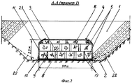
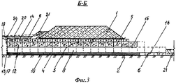
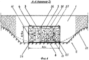
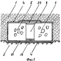
Предлагаемое изобретение иллюстрируется чертежами, на которых изображены: на фиг.1 - общий вид сооружения, план; на фиг.2 - разрез А-А на фиг.1, пример 1; на фиг.3 - разрез Б-Б на фиг.2, пример 1; на фиг.4 - разрез А-А на фиг.1, пример 2; на фиг.5 - одноярусная водопроводная часть сооружения с одним водопроводящим каналом, поперечный разрез.The present invention is illustrated by drawings, which depict: in Fig.1 - General view of the structure, plan; figure 2 is a section aa in figure 1, example 1; figure 3 is a section bB in figure 2, example 1; figure 4 is a section aa in figure 1, example 2; figure 5 is a single-tiered water part of the structure with one water channel, a cross section.
Пример 1 (фиг.1-3). Водопропускное сооружение расположено под насыпью 1 на относительно качественном основании 2 и включает водопроводную часть 3, заключенную в поперечном сечении в гибкую оболочку 4. Водопроводная часть 3 образована коробчатыми габионами (далее: габионы) 5 и 6, которые выполнены путем заполнения каменным материалом сетчатых металлических корзин прямоугольной формы [5].Example 1 (FIGS. 1-3). The culvert is located under the
Габионы 5 имеют размеры, например: длина L=1,5 м, ширина В=1,0 м, высота Н=1,0 м, а габионы 6 - соответственно: 3,0×1,0×0,5. Габионы 5 расположены в двух нижних ярусах. Эти габионы 5 своими рядами образуют в направлении продольной оси 7 водопропускного сооружения водопроводящие каналы (далее: каналы) 8 шириной, например, 0,25 м и каналы 9 (крайние в первом ярусе) шириной 0,125 м. Каналы 8 и 9 первого яруса перекрыты габионами 5 второго яруса, а дно этих каналов образовано защитным полотном 10. Каналы 8 второго яруса перекрыты габионами 6 третьего яруса, а дно этих каналов образовано габионами 5 первого яруса.
Указанные размеры габионов 5 и 6 и водопроводящих каналов 8 и 9 позволяют выполнить водопроводную часть 3 с вертикальными боковыми стенками 11, образовать входной оголовок 12 с вертикальной водоприемной стенкой 13 и водоприемным покрытием 14, а также выходной оголовок 15 и водобой 16. В водоприемной стенке 13 выполнены входные отверстия 17 каналов 8 и 9, а на самой стенке 13 закреплена сороудерживающая сетка 18, покрывающая всю наружную поверхность этой стенки 13. При этом размеры ячеек сороудерживающей сетки, по меньшей мере, в два раза меньше размеров ячеек сеток корзин габионов 5 и 6.The indicated dimensions of
В пределах крайних каналов 9 первого яруса установлены распорные элементы 19. Конструктивное выполнение этих распорных элементов 19 устанавливается проектом. При необходимости распорные элементы 19 могут быть установлены и в ряде каналов 8.Within the
Гибкая оболочка 4, а также защитное полотно 10 выполнены из геосинтетического материала, например геотекстиля (обычно нетканого), дорнита и других.The
На чертежах обозначены и другие элементы сооружения, а именно:In the drawings, other elements of the structure are indicated, namely:
20 - максимальный уровень воды;20 - maximum water level;
21 - крепление камнем;21 - mount with a stone;
22 - естественная поверхность основания;22 - natural surface of the base;
23 - крупнозернистый грунт;23 - coarse-grained soil;
24 - снег (с наледью).24 - snow (with ice).
Сооружение работает следующим образом.The construction works as follows.
При низких уровнях воды перед входным оголовком 12 вода движется под насыпью 1 по каналам 8 и 9 и фильтрует по порам габионов 5 первого (нижнего) яруса. При высоких уровнях воды дополнительно в работу включаются каналы 8 и габионы 5 второго яруса. При исключительно редком максимальном уровне воды 20 в работу включаются все каналы водопроводной части 3 и все ее габионы. При этом вода входит как через водоприемную стенку 13 входного оголовка 12, так и через его водоприемное покрытие 14. Последнее обстоятельство повышает полноту наполнения потоком каналов 8 и габионов 5 во втором ярусе, а также повышает работоспособность входного оголовка 12 в условиях занесения его снежными отложениями 24.At low water levels, in front of the inlet head 12, water moves under
При движении воды по фильтрующей части 3 происходит дренирование габионов 5 и 6 всех ярусов каналами 8 и 9. По мере приближения к выходному оголовку 15 вся вода из каналов 8 второго яруса может профильтровать через габионы 5 в каналы 8 и 9 первого яруса. Поэтому в случае отсутствия сороудерживающей сетки 18 может произойти засорение габионов 5 мусором, вошедшим через входные отверстия 17 каналов 8 второго яруса.When water moves along the filtering
Гибкая оболочка 4 предотвращает проникновение мелкодисперсных грунтов насыпи 1 и основания 2 в водопроводную часть 3 и вынос их потоком воды из насыпи, а полотно 10 совместно с гибкой оболочкой 4 защищает грунты основания 2 от размыва. Сороудерживающая сетка 18 защищает водопроводную часть 3, прежде всего ее фильтрующие габионы 5 и 6, от засорения, а энергия потока воды при выходе его из выходного оголовка 15 гасится в водобое 16.The
Пример 2 (фиг.4). Водопропускное сооружение расположено под насыпью 1 на относительно слабом основании 2 и характеризуется следующими, относительно примера 1, отличиями.Example 2 (figure 4). The culvert is located under the
1. Водопроводная часть 3 содержит постель 25, выполненную из матрасов Рена, которые представляют собой плоские прямоугольные габионы 26 небольшой толщины (матрацно-тюфячные габионы). Постель 25 расположена на гибкой оболочке 4 (взамен защитного полотна 10 или в дополнение к нему). Габионы 26 имеют размеры в метрах, например, 3,0×2,0×0,3.1. The
2. Габионы 5 первого и второго ярусов расположены друг над другом с образованием каналов 8 каждый шириной 0,25 м. Между этими ярусами и над ними расположены перекрытия, соответственно, 27 и 28, выполненные также из габионов 26.2.
Водопроводную часть 3 сооружения обычно выполняют многоярусной. По меньшей мере, она может состоять из одного яруса габионов, причем, как крайний случай, водопроводная часть 3 может содержать всего один канал, перекрытый плоским элементом 29 (фиг.5).The
Предлагаемое водопропускное сооружение по своей сути представляет собой комбинированное габионное сооружение, в котором вода под насыпью пропускается как по каналам, образованным габионами, так и по самим водопроницаемым габионам. При этом, если фильтрующую насыпь рекомендуется применять на водотоках с расчетным расходом до 5 м3/c [2], то в предлагаемом водопропускном сооружении такой расход может достигать 10 м3/c и более - в зависимости от размеров поперечного сечения водопроводной части сооружения и ее водопроводящих каналов.The proposed culvert is inherently a combined gabion structure in which water under the embankment is passed both through channels formed by gabions and through permeable gabions themselves. Moreover, if the filtering embankment is recommended to be used on waterways with a design flow rate of up to 5 m 3 / s [2], then in the proposed culvert, such a flow rate can reach 10 m 3 / s or more, depending on the size of the cross section of the water supply part of the structure its water channels.
Источники информацииInformation sources
1. Гибшман Е.Е. Мосты и сооружения на автомобильных дорогах. М.: Транспорт, 1973, стр.224, 225, фиг.114, 115.1. Gibshman E.E. Bridges and structures on the roads. M .: Transport, 1973, p. 244, 225, Fig. 114, 115.
2. Изыскания, проектирование и строительство железных дорог в районах вечной мерзлоты. ВСН 61-89 / Минтрансстрой СССР. - М.: ЦНИИС, 1990. Приложение 10, рис.1-3.2. Research, design and construction of railways in permafrost areas. BCH 61-89 / Ministry of Transport of the USSR. - M .: TsNIIS, 1990.
3. Патент Российской Федерации №2059031, кл. E01F 5/00, опубл. 27.04.1996.3. Patent of the Russian Federation No. 2059031, cl.
4. Патент Российской Федерации №2186170, кл. E01F 5/00, опубл. 27.07.2002.4. Patent of the Russian Federation No. 2186170, cl.
5. ГОСТ Р 52132-2003. Изделия из сетки для габионных конструкций. Технические условия.5. GOST R 52132-2003. Mesh products for gabion structures. Technical conditions
Claims (5)
Priority Applications (1)
| Application Number | Priority Date | Filing Date | Title |
|---|---|---|---|
| RU2008128826/03A RU2373329C1 (en) | 2008-07-14 | 2008-07-14 | Culvert under bank |
Applications Claiming Priority (1)
| Application Number | Priority Date | Filing Date | Title |
|---|---|---|---|
| RU2008128826/03A RU2373329C1 (en) | 2008-07-14 | 2008-07-14 | Culvert under bank |
Publications (1)
| Publication Number | Publication Date |
|---|---|
| RU2373329C1 true RU2373329C1 (en) | 2009-11-20 |
Family
ID=41477886
Family Applications (1)
| Application Number | Title | Priority Date | Filing Date |
|---|---|---|---|
| RU2008128826/03A RU2373329C1 (en) | 2008-07-14 | 2008-07-14 | Culvert under bank |
Country Status (1)
| Country | Link |
|---|---|
| RU (1) | RU2373329C1 (en) |
Cited By (2)
| Publication number | Priority date | Publication date | Assignee | Title |
|---|---|---|---|---|
| CN104018471A (en) * | 2014-06-16 | 2014-09-03 | 中国电建集团成都勘测设计研究院有限公司 | Blocking overflow dam structure |
| RU2567248C1 (en) * | 2014-08-21 | 2015-11-10 | Федеральное государственное бюджетное образовательное учреждение высшего профессионального образования "Дальневосточный государственный университет путей сообщения" (ДВГУПС) | Spillover on permafrost soils |
-
2008
- 2008-07-14 RU RU2008128826/03A patent/RU2373329C1/en active
Cited By (3)
| Publication number | Priority date | Publication date | Assignee | Title |
|---|---|---|---|---|
| CN104018471A (en) * | 2014-06-16 | 2014-09-03 | 中国电建集团成都勘测设计研究院有限公司 | Blocking overflow dam structure |
| CN104018471B (en) * | 2014-06-16 | 2016-07-13 | 中国电建集团成都勘测设计研究院有限公司 | Block overfall dam structure |
| RU2567248C1 (en) * | 2014-08-21 | 2015-11-10 | Федеральное государственное бюджетное образовательное учреждение высшего профессионального образования "Дальневосточный государственный университет путей сообщения" (ДВГУПС) | Spillover on permafrost soils |
Similar Documents
| Publication | Publication Date | Title |
|---|---|---|
| AU724847B2 (en) | Subsurface fluid drainage and storage systems | |
| CN108193758B (en) | Sponge urban road storing and draining structure | |
| JP2015183419A (en) | Ground formation method and ground structure | |
| KR101510615B1 (en) | Penetration type rainwater storage tank and construction method of the same | |
| RU2373329C1 (en) | Culvert under bank | |
| KR100821351B1 (en) | Constructing method of gabion used for ecological river | |
| RU2518634C2 (en) | Underflow filtering water intake of combined design | |
| KR101936013B1 (en) | Eco-friendly vegetative soil | |
| JP2963654B2 (en) | Ishiwari net revetment method | |
| TW201311971A (en) | Strata structure maintenance and underground water recharge/storage device | |
| RU2518452C2 (en) | Horizontal underground water intake of combined design | |
| RU2518456C2 (en) | Method to erect underflow filtering water intake of combined design | |
| CN213358503U (en) | Natural bank slope protective structure based on sponge city idea | |
| RU2375519C1 (en) | Culvert in conditions of permanently frozen soils on periodic water course | |
| RU2708769C1 (en) | Protective transport system of road structures and method of its erection | |
| KR100629152B1 (en) | Method and apparatus for earth and sand interception from erosion area | |
| JP2915389B1 (en) | Filtration type water storage tank device | |
| KR100449585B1 (en) | Vegetation revetment block and construction method using the same | |
| RU34945U1 (en) | Device for strengthening the slope of the soil structure | |
| RU2817417C2 (en) | Method of construction of combined water intake | |
| RU2614072C1 (en) | Combined drainage of earthworks | |
| RU2601802C1 (en) | Erection method of batter drainage earth structures | |
| CN213681983U (en) | Hydraulic engineering bank protection | |
| CN219862180U (en) | Grass planting ditch | |
| RU110760U1 (en) | DESIGN OF INPUT AND OUTPUT HEADS ON PIPELINES OF RAIN DRAINAGE |