RU2371814C2 - Method and device to assemble storage battery plates into packs and insert them into storage battery boxes - Google Patents
Method and device to assemble storage battery plates into packs and insert them into storage battery boxes Download PDFInfo
- Publication number
- RU2371814C2 RU2371814C2 RU2007123364/09A RU2007123364A RU2371814C2 RU 2371814 C2 RU2371814 C2 RU 2371814C2 RU 2007123364/09 A RU2007123364/09 A RU 2007123364/09A RU 2007123364 A RU2007123364 A RU 2007123364A RU 2371814 C2 RU2371814 C2 RU 2371814C2
- Authority
- RU
- Russia
- Prior art keywords
- plates
- packages
- section
- ears
- cassettes
- Prior art date
Links
- 238000000034 method Methods 0.000 title claims abstract description 42
- 238000003860 storage Methods 0.000 title abstract description 7
- 210000005069 ears Anatomy 0.000 claims abstract description 143
- 230000004907 flux Effects 0.000 claims abstract description 29
- 230000033001 locomotion Effects 0.000 claims description 77
- 238000009434 installation Methods 0.000 claims description 70
- 238000004140 cleaning Methods 0.000 claims description 16
- 238000005266 casting Methods 0.000 claims description 15
- 238000012545 processing Methods 0.000 claims description 13
- 238000005452 bending Methods 0.000 claims description 11
- 230000002441 reversible effect Effects 0.000 claims description 11
- 238000003780 insertion Methods 0.000 claims description 6
- 230000037431 insertion Effects 0.000 claims description 6
- 238000007781 pre-processing Methods 0.000 claims 2
- 238000002203 pretreatment Methods 0.000 claims 1
- 238000004870 electrical engineering Methods 0.000 abstract 1
- 239000000126 substance Substances 0.000 abstract 1
- 230000032258 transport Effects 0.000 description 25
- 210000002105 tongue Anatomy 0.000 description 21
- 229910000831 Steel Inorganic materials 0.000 description 10
- 239000010959 steel Substances 0.000 description 10
- 238000013461 design Methods 0.000 description 8
- 210000000883 ear external Anatomy 0.000 description 7
- 239000006260 foam Substances 0.000 description 7
- 230000006835 compression Effects 0.000 description 6
- 238000007906 compression Methods 0.000 description 6
- 230000001680 brushing effect Effects 0.000 description 5
- 230000009471 action Effects 0.000 description 4
- 229910000978 Pb alloy Inorganic materials 0.000 description 3
- 239000000463 material Substances 0.000 description 3
- 229910052751 metal Inorganic materials 0.000 description 3
- 239000002184 metal Substances 0.000 description 3
- 230000001681 protective effect Effects 0.000 description 3
- 125000006850 spacer group Chemical group 0.000 description 3
- 230000008901 benefit Effects 0.000 description 2
- 230000033228 biological regulation Effects 0.000 description 2
- 230000005540 biological transmission Effects 0.000 description 2
- 238000001035 drying Methods 0.000 description 2
- 238000010438 heat treatment Methods 0.000 description 2
- 238000004519 manufacturing process Methods 0.000 description 2
- 239000004033 plastic Substances 0.000 description 2
- 230000008569 process Effects 0.000 description 2
- 238000000926 separation method Methods 0.000 description 2
- 238000012546 transfer Methods 0.000 description 2
- 238000009423 ventilation Methods 0.000 description 2
- RZVAJINKPMORJF-UHFFFAOYSA-N Acetaminophen Chemical compound CC(=O)NC1=CC=C(O)C=C1 RZVAJINKPMORJF-UHFFFAOYSA-N 0.000 description 1
- 241000534414 Anotopterus nikparini Species 0.000 description 1
- 229930182670 Astin Natural products 0.000 description 1
- 206010051602 Laziness Diseases 0.000 description 1
- 244000089486 Phragmites australis subsp australis Species 0.000 description 1
- 235000014676 Phragmites communis Nutrition 0.000 description 1
- 239000002253 acid Substances 0.000 description 1
- 229910052782 aluminium Inorganic materials 0.000 description 1
- XAGFODPZIPBFFR-UHFFFAOYSA-N aluminium Chemical compound [Al] XAGFODPZIPBFFR-UHFFFAOYSA-N 0.000 description 1
- 238000007664 blowing Methods 0.000 description 1
- 239000000969 carrier Substances 0.000 description 1
- 230000008859 change Effects 0.000 description 1
- 238000001816 cooling Methods 0.000 description 1
- 230000007423 decrease Effects 0.000 description 1
- 230000001419 dependent effect Effects 0.000 description 1
- 238000006073 displacement reaction Methods 0.000 description 1
- 239000000428 dust Substances 0.000 description 1
- 238000009429 electrical wiring Methods 0.000 description 1
- 238000005516 engineering process Methods 0.000 description 1
- 238000000605 extraction Methods 0.000 description 1
- 238000011010 flushing procedure Methods 0.000 description 1
- 230000010354 integration Effects 0.000 description 1
- 238000012423 maintenance Methods 0.000 description 1
- 230000014759 maintenance of location Effects 0.000 description 1
- 230000013011 mating Effects 0.000 description 1
- 239000002245 particle Substances 0.000 description 1
- 239000004417 polycarbonate Substances 0.000 description 1
- 229920000515 polycarbonate Polymers 0.000 description 1
- 230000008707 rearrangement Effects 0.000 description 1
- 239000002893 slag Substances 0.000 description 1
- 239000010802 sludge Substances 0.000 description 1
- 230000001360 synchronised effect Effects 0.000 description 1
Images


Classifications
-
- B—PERFORMING OPERATIONS; TRANSPORTING
- B22—CASTING; POWDER METALLURGY
- B22D—CASTING OF METALS; CASTING OF OTHER SUBSTANCES BY THE SAME PROCESSES OR DEVICES
- B22D25/00—Special casting characterised by the nature of the product
- B22D25/02—Special casting characterised by the nature of the product by its peculiarity of shape; of works of art
- B22D25/04—Casting metal electric battery plates or the like
-
- H—ELECTRICITY
- H01—ELECTRIC ELEMENTS
- H01M—PROCESSES OR MEANS, e.g. BATTERIES, FOR THE DIRECT CONVERSION OF CHEMICAL ENERGY INTO ELECTRICAL ENERGY
- H01M10/00—Secondary cells; Manufacture thereof
- H01M10/04—Construction or manufacture in general
- H01M10/0404—Machines for assembling batteries
-
- H—ELECTRICITY
- H01—ELECTRIC ELEMENTS
- H01M—PROCESSES OR MEANS, e.g. BATTERIES, FOR THE DIRECT CONVERSION OF CHEMICAL ENERGY INTO ELECTRICAL ENERGY
- H01M10/00—Secondary cells; Manufacture thereof
- H01M10/04—Construction or manufacture in general
- H01M10/049—Processes for forming or storing electrodes in the battery container
-
- H—ELECTRICITY
- H01—ELECTRIC ELEMENTS
- H01M—PROCESSES OR MEANS, e.g. BATTERIES, FOR THE DIRECT CONVERSION OF CHEMICAL ENERGY INTO ELECTRICAL ENERGY
- H01M10/00—Secondary cells; Manufacture thereof
- H01M10/06—Lead-acid accumulators
- H01M10/12—Construction or manufacture
- H01M10/121—Valve regulated lead acid batteries [VRLA]
-
- H—ELECTRICITY
- H01—ELECTRIC ELEMENTS
- H01M—PROCESSES OR MEANS, e.g. BATTERIES, FOR THE DIRECT CONVERSION OF CHEMICAL ENERGY INTO ELECTRICAL ENERGY
- H01M10/00—Secondary cells; Manufacture thereof
- H01M10/06—Lead-acid accumulators
- H01M10/12—Construction or manufacture
- H01M10/14—Assembling a group of electrodes or separators
-
- H—ELECTRICITY
- H01—ELECTRIC ELEMENTS
- H01M—PROCESSES OR MEANS, e.g. BATTERIES, FOR THE DIRECT CONVERSION OF CHEMICAL ENERGY INTO ELECTRICAL ENERGY
- H01M10/00—Secondary cells; Manufacture thereof
- H01M10/06—Lead-acid accumulators
- H01M10/12—Construction or manufacture
- H01M10/16—Suspending or supporting electrodes or groups of electrodes in the case
-
- Y—GENERAL TAGGING OF NEW TECHNOLOGICAL DEVELOPMENTS; GENERAL TAGGING OF CROSS-SECTIONAL TECHNOLOGIES SPANNING OVER SEVERAL SECTIONS OF THE IPC; TECHNICAL SUBJECTS COVERED BY FORMER USPC CROSS-REFERENCE ART COLLECTIONS [XRACs] AND DIGESTS
- Y02—TECHNOLOGIES OR APPLICATIONS FOR MITIGATION OR ADAPTATION AGAINST CLIMATE CHANGE
- Y02E—REDUCTION OF GREENHOUSE GAS [GHG] EMISSIONS, RELATED TO ENERGY GENERATION, TRANSMISSION OR DISTRIBUTION
- Y02E60/00—Enabling technologies; Technologies with a potential or indirect contribution to GHG emissions mitigation
- Y02E60/10—Energy storage using batteries
-
- Y—GENERAL TAGGING OF NEW TECHNOLOGICAL DEVELOPMENTS; GENERAL TAGGING OF CROSS-SECTIONAL TECHNOLOGIES SPANNING OVER SEVERAL SECTIONS OF THE IPC; TECHNICAL SUBJECTS COVERED BY FORMER USPC CROSS-REFERENCE ART COLLECTIONS [XRACs] AND DIGESTS
- Y02—TECHNOLOGIES OR APPLICATIONS FOR MITIGATION OR ADAPTATION AGAINST CLIMATE CHANGE
- Y02P—CLIMATE CHANGE MITIGATION TECHNOLOGIES IN THE PRODUCTION OR PROCESSING OF GOODS
- Y02P70/00—Climate change mitigation technologies in the production process for final industrial or consumer products
- Y02P70/50—Manufacturing or production processes characterised by the final manufactured product
-
- Y—GENERAL TAGGING OF NEW TECHNOLOGICAL DEVELOPMENTS; GENERAL TAGGING OF CROSS-SECTIONAL TECHNOLOGIES SPANNING OVER SEVERAL SECTIONS OF THE IPC; TECHNICAL SUBJECTS COVERED BY FORMER USPC CROSS-REFERENCE ART COLLECTIONS [XRACs] AND DIGESTS
- Y10—TECHNICAL SUBJECTS COVERED BY FORMER USPC
- Y10T—TECHNICAL SUBJECTS COVERED BY FORMER US CLASSIFICATION
- Y10T29/00—Metal working
- Y10T29/49—Method of mechanical manufacture
- Y10T29/49002—Electrical device making
- Y10T29/49108—Electric battery cell making
-
- Y—GENERAL TAGGING OF NEW TECHNOLOGICAL DEVELOPMENTS; GENERAL TAGGING OF CROSS-SECTIONAL TECHNOLOGIES SPANNING OVER SEVERAL SECTIONS OF THE IPC; TECHNICAL SUBJECTS COVERED BY FORMER USPC CROSS-REFERENCE ART COLLECTIONS [XRACs] AND DIGESTS
- Y10—TECHNICAL SUBJECTS COVERED BY FORMER USPC
- Y10T—TECHNICAL SUBJECTS COVERED BY FORMER US CLASSIFICATION
- Y10T29/00—Metal working
- Y10T29/52—Plural diverse manufacturing apparatus
-
- Y—GENERAL TAGGING OF NEW TECHNOLOGICAL DEVELOPMENTS; GENERAL TAGGING OF CROSS-SECTIONAL TECHNOLOGIES SPANNING OVER SEVERAL SECTIONS OF THE IPC; TECHNICAL SUBJECTS COVERED BY FORMER USPC CROSS-REFERENCE ART COLLECTIONS [XRACs] AND DIGESTS
- Y10—TECHNICAL SUBJECTS COVERED BY FORMER USPC
- Y10T—TECHNICAL SUBJECTS COVERED BY FORMER US CLASSIFICATION
- Y10T29/00—Metal working
- Y10T29/54—Miscellaneous apparatus
Abstract
Description
Изобретение относится к способу и установке для соединения ушек пластин аккумулятора (положительных и отрицательных пластин) с помощью мостов и вставки полученных таким образом пакетов из пластин аккумулятора, ушки которых соединены друг с другом мостами, в аккумуляторные ящики.The invention relates to a method and installation for connecting the ears of the battery plates (positive and negative plates) using bridges and inserting the packages thus obtained from the battery plates, the ears of which are connected to each other by bridges, in the battery boxes.
Для соединения ушек пластин аккумулятора с помощью мостов известны различные установки. Известна установка фирмы DAGA S.r.l in Centro Colleoni Palazzo Andromeda, I-20041 Agrate Brianza, Mailand (IT) (“COS/2000 & 1000 CAST ON STRAP SYSTEMS”), с помощью которой установленные в держателях пластины аккумулятора перемещаются шаг за шагом от участка к участку для осуществления отдельных стадий обработки с целью соединения ушек с помощью мостов.Various installations are known for connecting the ears of the battery plates using bridges. A known installation of the company DAGA Srl in Centro Colleoni Palazzo Andromeda, I-20041 Agrate Brianza, Mailand (IT) (“COS / 2000 & 1000 CAST ON STRAP SYSTEMS”), with which the battery plates installed in the holders are moved step by step from section to section for the implementation of the individual stages of processing in order to connect the ears using bridges.
Для соединения ушек пластин аккумулятора с помощью мостов, которые затем вставляются в аккумуляторные ящики, известны также круглые тактовые столы (изготовитель: TBS Engineering, Ltd., Cheltenham, U.K. и Sovema S.p.A. in Villafranca, Италия). Эти известные круглые тактовые столы имеют четыре носителя для подлежащих обработке пластин аккумулятора, которые шаг за шагом перемещаются далее.To connect the ears of the battery plates using bridges, which are then inserted into the battery boxes, round clock tables are also known (manufacturer: TBS Engineering, Ltd., Cheltenham, U.K. and Sovema S.p.A. in Villafranca, Italy). These well-known round clock tables have four carriers for the battery plates to be processed, which move forward step by step.
Недостатком известных способов и установок является то, что они имеют ограниченную производительность и лишь с трудом согласовываются с различными типами батарей и аккумуляторов (аккумуляторы для легковых автомобилей, аккумуляторы для грузовых автомобилей или аккумуляторы для промышленного применения, как, например, для автопогрузчиков или т.п.).A disadvantage of the known methods and installations is that they have limited performance and only with difficulty are compatible with various types of batteries and accumulators (batteries for cars, batteries for trucks or batteries for industrial applications, such as for forklifts or the like .).
В основу изобретения положена задача создания способа и установки, с помощью которых повышается производительность, и изготовление пакетов пластин аккумулятора, ушки которых соединены друг с другом с помощью мостов, и их вставка в аккумуляторные ящики может выполняться более рационально и гораздо быстрее.The basis of the invention is the creation of a method and installation, which increases productivity, and the manufacture of packages of battery plates, the ears of which are connected to each other using bridges, and their insertion into battery boxes can be performed more rationally and much faster.
Эта задача решена, в первую очередь, с помощью способа, который имеет признаки независимого пункта на способ формулы изобретения.This problem is solved, first of all, using a method that has the characteristics of an independent claim on the method of the claims.
Относительно установки согласно изобретению эта задача решена с помощью установки (устройства), которая имеет признаки независимого пункта на установку формулы изобретения.Regarding the installation according to the invention, this problem is solved by using the installation (device), which has the characteristics of an independent paragraph on the installation of the claims.
Предпочтительные и преимущественные варианты выполнения способа и установки согласно изобретению являются предметом зависимых пунктов формулы изобретения.Preferred and advantageous embodiments of the method and installation according to the invention are the subject of the dependent claims.
С помощью способа согласно изобретению обеспечивается производительность до шести (6) - девяти (9) аккумуляторов в минуту. Кроме того, изобретение обеспечивает простую интеграцию всех рабочих стадий в этот способ или, соответственно, в эту установку.Using the method according to the invention provides the performance of up to six (6) - nine (9) batteries per minute. In addition, the invention provides a simple integration of all work stages in this method or, accordingly, in this installation.
За счет осуществленной в изобретении предпочтительно линейной и модульной концепции можно способ и установку согласно изобретению просто согласовывать с требованиями пользователя.Due to the preferably linear and modular concept implemented in the invention, the method and installation according to the invention can simply be adapted to the requirements of the user.
Преимуществом изобретения является то, что можно просто выполнять отдельные стадии, что все участки установки просто и хорошо доступны и что как способ, так и установку можно гибко изменять. Это, в частности, относится к случаю, когда для транспортировки пакетов пластин при осуществлении способа согласно изобретению применяют предложенные в качестве составной части изобретения транспортные кассеты.An advantage of the invention is that it is possible to simply carry out individual steps, that all parts of the installation are simple and well accessible, and that both the method and the installation can be flexibly changed. This, in particular, relates to the case when transport cartridges proposed as an integral part of the invention are used for transporting plate packs during the implementation of the method according to the invention.
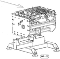
В одном примере выполнения установка согласно изобретению содержит устойчивую машинную раму с интегрированным вентиляционным каналом и защитными крышками. В предусмотренную машинную раму установки согласно изобретению могут быть интегрированы все компоненты для транспортировки кассет, в которых установлены пластины аккумулятора, вентиляционные каналы и электрическая проводка.In one embodiment, the installation according to the invention comprises a stable machine frame with an integrated ventilation duct and protective covers. All components for transporting cassettes in which battery plates, ventilation ducts and electrical wiring can be integrated into the machine frame of the installation according to the invention can be integrated.
По причинам безопасности большинство областей может быть покрыто защитными крышками (например, поликарбонатными дисками с алюминиевыми рамами), которые могут быть снабжены защитными переключателями. Это выполнение обеспечивает простой доступ ко всем частям установки для очистки и технического обслуживания.For safety reasons, most areas may be covered with protective covers (e.g. polycarbonate discs with aluminum frames), which may be equipped with protective switches. This design provides easy access to all parts of the installation for cleaning and maintenance.
В одном примере выполнения изобретения предусмотрена замкнутая траектория движения с четырьмя (прямыми) отрезками движения, на углах которых предусмотрены участки перестановки для предпочтительно применяемых кассет, в которых транспортируются пакеты пластин.In one exemplary embodiment of the invention, a closed path with four (straight) segments of movement is provided, at the corners of which there are permutation sections for the preferred cartridges in which plate packs are transported.
Например, первый отрезок траектории движения транспортирует пустые кассеты в один или два участка загрузки и из них через участок выравнивания ушек и пластин - к первому перестановочному участку. На первом участке перестановки направление движения кассет изменяется на 90°, так что они могут транспортироваться вдоль второго отрезка траектории движения.For example, the first segment of the trajectory moves empty cartridges into one or two loading sections and from them through the alignment section of the ears and plates to the first permutation section. In the first section of the permutation, the direction of movement of the cartridges changes by 90 °, so that they can be transported along the second segment of the trajectory of movement.
Второй отрезок траектории движения разделен, например, на четыре частичных отрезка. Первый частичный отрезок перемещает нагруженные пластинами кассеты прерывисто из первого перестановочного участка на участок сгибания ушек, на участок поворота и на участок для очистки щетками ушек аккумуляторных пластин.The second segment of the motion path is divided, for example, into four partial segments. The first partial segment moves the cassettes loaded with the plates intermittently from the first permutation section to the ears bending section, to the turning section and to the brush cleaning section of the ears of the battery plates.
В одном варианте выполнения второй частичный отрезок второго отрезка траектории движения перемещает одну кассету - при свободном пространстве в одной или двух последующих буферных участках - из участка для обработки ушек флюсом (участок флюса) в буферную зону и одну кассету из участка для очистки щетками ушек на участок для обработки флюсом. На следующей рабочей стадии второй частичный отрезок второго отрезка траектории движения перемещает одну, две или три кассеты в литейный участок, на котором к ушкам приливаются мосты.In one embodiment, the second partial segment of the second segment of the trajectory moves one cartridge - with free space in one or two subsequent buffer sections - from the section for processing the ears with flux (section of the flux) to the buffer zone and one cartridge from the section for brushing the ears to the section for flux treatment. At the next working stage, the second partial segment of the second segment of the trajectory moves one, two or three cartridges into the casting section, on which bridges are poured to the ears.
Третий частичный отрезок второго отрезка траектории движения перемещает в одном примере выполнения кассеты в двух или трех литейных участках и перемещает их, соответственно, на два или три шага дальше.The third partial segment of the second segment of the motion path moves in one embodiment of the cartridge in two or three casting sections and moves them, respectively, two or three steps further.
Четвертый частичный отрезок второго отрезка траектории движения транспортирует в одном примере выполнения кассеты по отдельности через буферную зону и через поворотный участок ко второму угловому перестановочному участку.The fourth partial segment of the second segment of the motion path transports, in one example, the execution of the cartridge individually through the buffer zone and through the rotary section to the second angular permutation section.
Третий отрезок траектории движения транспортирует в одном примере выполнения кассеты от второго перестановочного участка к третьему перестановочному участку. На этом третьем отрезке траектории движения предусмотрен участок для извлечения пакетов из транспортных кассет. Этот участок может иметь два параллельных перестановщика (комплекта захватов), которые извлекают по три пакета пластин. Извлеченные пакеты пластин в данном примере устанавливаются параллельными перестановщиками в отделения для ячеек в аккумуляторных ящиках.The third segment of the motion path transports in one example the execution of the cartridge from the second permutation section to the third permutation section. On this third section of the trajectory, a section is provided for extracting packets from the transport cassettes. This section may have two parallel permutators (sets of grips) that extract three sets of plates. The extracted plate packs in this example are installed by parallel switchers in the cell compartments in the battery boxes.
Из третьего перестановочного участка в одном примере выполнения пустые кассеты перемещаются по четвертому отрезку траектории движения снова к первому отрезку траектории движения. Этот четвертый отрезок траектории движения замыкает через четвертый перестановочный участок контур и транспортирует пустые кассеты снова к первому отрезку траектории движения.From the third permutation section, in one embodiment, empty cartridges move along the fourth segment of the motion path again to the first segment of the motion path. This fourth segment of the motion path closes the contour through the fourth permutation segment and transports empty cartridges again to the first segment of the motion path.
Предпочтительно используемые в рамках изобретения кассеты выполнены, например, для аккумуляторов легковых автомобилей, аккумуляторов грузовых автомобилей или для аккумуляторов VRLA. Кассеты для аккумуляторов легковых автомобилей выполнены так, что их можно загружать пакетами пластин для шести ячеек с толщиной от 22 до 55 мм. Кассеты для грузовых автомобилей можно загружать пакетами пластин для шести ячеек с толщиной от 50 до 120 мм. Оба типа кассет можно применять также для так называемых аккумуляторов VRLA (кислотные свинцовые аккумуляторы с регулируемыми клапанами).Preferably used in the framework of the invention cassettes are made, for example, for passenger car batteries, truck batteries or for VRLA batteries. Cassettes for passenger car batteries are designed so that they can be loaded with plate packs for six cells with a thickness of 22 to 55 mm. Cartridges for trucks can be loaded with plate packs for six cells with a thickness of 50 to 120 mm. Both types of cassettes can also be used for so-called VRLA batteries (acid lead batteries with adjustable valves).
В одном предпочтительном варианте выполнения изобретения кассеты автоматически открываются на участке загрузки для загрузки пакетов пластин посредством перемещения нагруженных пружинами подвижных стенок от неподвижных стенок кассет. После загрузки кассета закрывается, и пакеты пластин зажимаются между нагруженными пружинами, подвижными стенками и неподвижными стенками. Аналогичные движения подвижных стенок для освобождения, соответственно, фиксации пакетов пластин в кассетах выполняются в участках для выравнивания ушек и аккумуляторных пластин, а также на участке разгрузки для освобождения пластин.In one preferred embodiment of the invention, the cassettes automatically open in the loading area to load plate packs by moving the spring-loaded moving walls from the fixed walls of the cassettes. After loading, the cassette closes, and the plate packs are clamped between loaded springs, movable walls and fixed walls. Similar movements of the movable walls to release, respectively, the fixation of the plate packs in the cassettes are performed in sections for aligning the ears and battery plates, as well as in the unloading area to release the plates.
На участке загрузки в одном примере выполнения применяются шесть захватов, которые принимают пакеты аккумуляторных пластин (положительных пластин и отрицательных пластин) с транспортера и устанавливают в кассеты. Участок загрузки может быть в зависимости от условий снабжен параллельными захватами или же, например, одним поворотным рычагом. В предпочтительном варианте выполнения на участке загрузки согласно изобретению нет необходимости в согласовании с различной шириной пластин. Различная высота пластин компенсируется посредством, например, установки стола под кассетами в соответствии с высотой пластин.At the loading site, in one embodiment, six grippers are used that receive packs of battery plates (positive plates and negative plates) from the conveyor and are installed in cassettes. The loading section may be equipped with parallel grippers, or, for example, with one pivoting lever, depending on the conditions. In a preferred embodiment, the loading area according to the invention does not need to be matched to different plate widths. The different height of the plates is compensated by, for example, setting the table under the cassettes in accordance with the height of the plates.
Для обращения с пластинами для аккумуляторов легковых автомобилей, с одной стороны, и пластинами для аккумуляторов грузовых автомобилей или аккумуляторов VRLA, с другой стороны, можно заменять захваты участка загрузки. Участок для выравнивания ушек и аккумуляторных пластин легко согласовывать с различными положениями ушек. Наряду с этим регулированием в определенных случаях необходимо также регулирование с учетом высоты пластин, чтобы все верхние кромки ушек были расположены на одинаковой высоте. Для различной ширины пластин регулирование не требуется.To handle the plates for passenger car batteries, on the one hand, and the plates for truck batteries or VRLA batteries, on the other hand, the grips of the loading section can be replaced. The area for aligning the ears and the battery plates is easy to align with different positions of the ears. Along with this regulation, in certain cases it is also necessary to adjust to the height of the plates so that all the upper edges of the ears are at the same height. For different plate widths, adjustment is not required.
Шесть пакетов пластин в одном предпочтительном варианте выполнения выравниваются не только по сторонам, но также по ушкам для обеспечения правильного выравнивания. Переставляемый по высоте стол, на который опираются пластины во время выравнивания, может быть снабжен (электрическим или пневматическим) вибратором. Переходную плиту для различной высоты пластин можно в одном варианте выполнения заменять без применения инструмента.Six packs of plates in one preferred embodiment are aligned not only on the sides, but also on the ears to ensure proper alignment. The height-adjustable table on which the plates rest during alignment can be equipped with a (electric or pneumatic) vibrator. The adapter plate for different plate heights can, in one embodiment, be replaced without a tool.
На участке для сгибания ушек, которые могут быть выполнены различно для аккумуляторов легковых автомобилей, с одной стороны, и для аккумуляторов грузовых автомобилей, с другой стороны, в одном примере выполнения сгибаются наружные ушки каждого пакета пластин для того, чтобы их позже без проблем вводить в литейную форму. На этом участке не требуется регулирования для различных положений или выравниваний ушек.In the section for folding ears, which can be made differently for passenger car batteries, on the one hand, and for truck batteries, on the other hand, in one embodiment, the outer ears of each package of plates are bent so that they can be inserted into the later without problems mold. This section does not require adjustment for different positions or alignment of the ears.
На следующем участке в одном примере выполнения кассеты со снова зажатыми пакетами пластин поворачиваются на 180°, так что ушки теперь направлены вниз.In the next section, in one exemplary embodiment, the cassettes with the packets of plates clamped again rotate 180 ° so that the ears are now pointing down.
На расположенном под ними участке в одном примере выполнения ушки пластин очищаются с помощью, например, двух вращающихся круглых щеток (стальных щеток).In a section located beneath them, in one embodiment, the ears of the plates are cleaned with, for example, two rotating round brushes (steel brushes).
На следующем участке в одном примере выполнения ушки обрабатываются флюсом посредством погружения их в ванну с флюсом. Ванна с флюсом предпочтительно расположена в пенопласте, т.е. пенопласт пропитан флюсом. Уровень флюса в пенопласте (эластичном пенопласте) автоматически контролируется. При необходимости на этом участке предусмотрено также устройство для сушки ушек после обработки флюсом.In the next section, in one embodiment, the ears are treated with flux by immersing them in a flux bath. The flux bath is preferably located in the foam, i.e. the foam is impregnated with flux. The level of flux in the foam (elastic foam) is automatically controlled. If necessary, a device for drying the ears after flux treatment is also provided on this site.
При необходимости может быть дополнительно предусмотрен участок лужения, в котором ушки подвергаются лужению.If necessary, a tinning section may be additionally provided in which the ears are tinned.
На следующем участке в одном примере выполнения приливаются мосты, которые соединяют друг с другом, с одной стороны, положительные пластины и, с другой стороны, отрицательные пластины. При этом предусмотрено, что все ушки положительных пластин расположены на одной стороне формы, а все ушки отрицательных пластин - на другой стороне. Все формы для прилива соединительных мостов работают независимо друг от друга. Формы предпочтительно предварительно нагревают на столе предварительного нагревания.In the following section, in one embodiment, bridges are poured that connect, on the one hand, positive plates and, on the other hand, negative plates. It is provided that all the ears of the positive plates are located on one side of the mold, and all the ears of the negative plates are on the other side. All forms for connecting bridge tide work independently of each other. The molds are preferably preheated on a preheating table.
Свинец (или свинцовый сплав) для прилива соединительных мостов к пакетам пластин можно расплавлять посредством нагревания газом или электрически. Дозирование расплавленного свинца при заливке приливных форм можно также осуществлять полностью автоматически.Lead (or lead alloy) for flushing the connecting bridges to the stacks of plates can be melted by heating with gas or electrically. Dosing molten lead when pouring tidal forms can also be carried out fully automatically.
После прилива мостов (предпочтительно из свинца или свинцового сплава) в одном примере выполнения кассеты транспортируются на следующий участок, на котором кассеты снова поворачиваются, так что ушки, которые теперь соединены (свинцовыми) мостами, снова направлены вверх.After the tide of the bridges (preferably from lead or lead alloy), in one embodiment, the cassettes are transported to the next section, where the cassettes rotate again, so that the ears, which are now connected by (lead) bridges, are directed upward again.
На следующем за ним участке разгрузки в одном примере выполнения последовательно извлекаются с помощью комплектов захватов по три и три пакета для ячеек. Каждый комплект захватов участка для извлечения пакетов пластин снабжен, например, тремя (тонко выполненными) захватами. Захваты перемещаются в одном примере выполнения параллельно и обеспечивают надежный захват и вставку готовых пакетов пластин в аккумуляторные ящики. При этом первые три ячейки предпочтительно извлекаются из кассеты первыми тремя захватами первого параллельного перестановщика участка разгрузки и устанавливаются в отделения аккумуляторного ящика для ячеек «1», «3» и «5». Пакеты пластин для ячеек «6», «4» и «2» извлекаются из кассеты вторым параллельным перестановщиком и устанавливаются в отделения аккумуляторного ящика для ячеек «6», «4» и «2».In the next unloading section, in one embodiment, three and three packets for the cells are sequentially extracted using sets of grippers. Each set of grippers of the plate pack extraction section is provided with, for example, three (finely made) grippers. Grips move in one embodiment in parallel and provide reliable grip and insertion of finished plate packs into battery boxes. In this case, the first three cells are preferably removed from the cassette by the first three grippers of the first parallel switcher of the discharge section and are installed in the battery compartment for the cells "1", "3" and "5". Packets of plates for cells "6", "4" and "2" are removed from the cassette by a second parallel switcher and installed in the compartment of the battery box for cells "6", "4" and "2".
Для обеспечения надежной установки пакетов пластин в отделения для ячеек в аккумуляторных ящиках над аккумуляторным ящиком может быть предусмотрена направляющая, в частности, из стального листа или пластмассы.To ensure reliable installation of the plate packs in the cell compartments in the battery boxes, a guide may be provided above the battery box, in particular of steel sheet or plastic.
Транспортировочное устройство для подачи аккумуляторных ящиков обеспечивает точное расположение аккумуляторных ящиков, в которые подлежат установке пакеты пластин, в области участка разгрузки.The transport device for feeding the battery boxes ensures the exact location of the battery boxes in which the plate packs are to be installed in the area of the discharge section.
Установка согласно изобретению может быть снабжена вертикальным накопителем типа подъемника непрерывного действия для замены кассет для пластин аккумуляторов легковых автомобилей, с одной стороны, кассетами для пластин аккумуляторов грузовых автомобилей, с другой стороны, и наоборот. В качестве примера для этого предусмотрены два штабелирующих устройства (типа подъемника непрерывного действия) для таких кассет.The installation according to the invention can be equipped with a vertical storage device such as a continuous lift for replacing cassettes for battery plates of cars, on the one hand, cassettes for battery plates of trucks, on the other hand, and vice versa. As an example, two stacking devices (such as a continuous lift) for such cassettes are provided for this.
Ниже приводится описание вариантов выполнения установки согласно изобретению, с помощью которой можно реализовать способ согласно изобретению.Below is a description of embodiments of the installation according to the invention, with which you can implement the method according to the invention.
ПЕРВЫЙ УЧАСТОК:FIRST PLOT:
Вставка шести пакетов пластин в держатели (транспортные кассеты) с помощью системы с шестью захватами (либо посредством параллельного переноса пакетов пластин, либо с помощью поворачиваемого на 90° захвата).Insert six packs of plates into holders (transport cassettes) using a system with six grippers (either by parallel transfer of packs of plates, or by using a 90 ° swivel gripper).
ВТОРОЙ УЧАСТОК:SECOND STATION:
На этом участке выравниваются пластины и их ушки, при этом для выравнивания пластин частично ослабляется их зажимание в кассетах, и выполняется постукивание планками (выравнивающими планками) по пластинам для их выравнивания на одной линии друг с другом. Аналогичное действие выполняется с ушками с помощью других выравнивающих планок. После выравнивания пакеты пластин снова зажимаются в кассетах.In this section, the plates and their ears are aligned, while for alignment of the plates, their clamping in the cassettes is partially weakened, and the bars (leveling bars) tap on the plates to align them on the same line with each other. A similar action is performed with the ears using other leveling strips. After alignment, the plate packs are clamped again in the cassettes.
ТРЕТИЙ УЧАСТОК:THIRD PART:
Угловой перестановщик: здесь направление движения изменяется на 90° (по часовой стрелке).Corner switcher: here the direction of movement changes by 90 ° (clockwise).
ЧЕТВЕРТЫЙ УЧАСТОК:FOURTH SECTION:
На этом участке два наружных ушка каждого пакета пластин отгибаются внутрь, что является важным для прилива мостов. Для этого предусмотрены отгибающие планки с клиновидными поверхностями и с упором, при этом оба наружных ушка с помощью клиновидных поверхностей отгибаются внутрь, так что они располагаются наклонно.In this section, the two outer ears of each package of plates are folded inward, which is important for the tide of bridges. To do this, bending plates with wedge-shaped surfaces and with a stop are provided, while both outer ears with the help of wedge-shaped surfaces are bent inward, so that they are inclined.
ПЯТЫЙ УЧАСТОК:FIFTH SECTION:
На этом участке кассеты с зажатыми в них пакетами пластин поворачиваются так, что ушки теперь направлены вниз. Для этого предусмотрен скобообразный держатель с двумя конусными пальцами, которые входят в соответствующие выемки на узких сторонах кассет, при этом конус, который входит в зацепление с геометрическим зацеплением, снабжен поворотным приводом.In this section, the cassettes with the packages of plates clamped in them are rotated so that the ears are now directed downward. For this, a staple-shaped holder with two conical fingers that fit into the corresponding recesses on the narrow sides of the cassettes is provided, while the cone, which engages with geometric engagement, is equipped with a rotary drive.
ШЕСТОЙ УЧАСТОК:SIXTH SECTION:
На этом участке ушки очищаются щетками до блеска. Для этого предусмотрены два удлиненных щеточных валика (круглые проволочные щетки), которые приводятся во вращение в противоположных направлениях. Под щеточными валиками предусмотрена улавливающая ванна с отсосом для счищаемого с ушек материала.In this area, the ears are brushed to a shine. For this, two elongated brush rollers (round wire brushes) are provided, which are driven in rotation in opposite directions. Under the brush rollers there is a catching bath with a suction for material to be cleaned from the ears.
СЕДЬМОЙ УЧАСТОК:SEVENTH SECTION:
На этом участке ушки перед приливом мостов обрабатываются флюсом. Для этого на участке предусмотрена ванна, в которой размещена губка, которая пропитана флюсом. Эта ванна поднимается, пока ушки не погрузятся в губку с флюсом. После опускания ванны на ушки направляется через боковые трубы теплый воздух для их сушки.In this section, the ears are treated with flux before the tide of bridges. For this, a bath is provided on the site, in which a sponge is placed, which is impregnated with flux. This bath rises until the ears sink into a sponge with flux. After lowering the bath, warm air is sent to the ears through the side pipes to dry them.
В качестве альтернативного решения, флюс можно наносить также с помощью (медленно) вращающихся (пластмассовых) щеток. Эти щетки, которые могут быть, в частности, круглыми щетками, установлены так, что их направленные вниз части (щетинки) погружаются, по меньшей мере, в одну ванну с флюсом.As an alternative solution, flux can also be applied using (slowly) rotating (plastic) brushes. These brushes, which can be, in particular, round brushes, are installed so that their downwardly directed parts (bristles) are immersed in at least one flux bath.
ВОСЬМОЙ УЧАСТОК:EIGHTH SECTION:
На этом буферном участке собираются кассеты с пакетами пластин, ушки которых были обработаны флюсом, так что затем можно перемещать далее две и две или три и три кассеты.In this buffer section, cassettes with packs of plates are assembled, the ears of which were flux-treated, so that then two, two, three or three cassettes can be moved further.
ДЕВЯТЫЙ УЧАСТОК:NINTH SECTION:
На этом участке приливаются мосты с фланцами для промежуточных соединений ячеек («межъячеечные соединения») и полюсные цапфы. При этом пластины устанавливаются в кассетах так, что на одной продольной стороне предусмотрены исключительно ушки положительных аккумуляторных пластин, а на другой стороне - исключительно ушки отрицательных аккумуляторных пластин. Это позволяет учитывать различную толщину и величину положительных ушек, с одной стороны, и отрицательных ушек, с другой стороны, при приливе мостов, посредством учета различного поведения ушек при охлаждении, обусловленного различной массой ушек.On this section, bridges with flanges for intermediate cell connections (“intercell connections”) and pole trunks are joined. In this case, the plates are installed in the cassettes so that on one longitudinal side exclusively the ears of the positive battery plates are provided, and on the other side - exclusively the ears of the negative battery plates. This allows you to take into account the different thickness and size of the positive ears, on the one hand, and the negative ears, on the other hand, when the bridges rush, by taking into account the different behavior of the ears during cooling, due to the different mass of the ears.
ДЕСЯТЫЙ УЧАСТОК:TENTH SECTION:
Это - буферный участок, аналогичный восьмому участку.This is a buffer section similar to the eighth section.
ОДИННАДЦАТЫЙ УЧАСТОК:ELEVENTH PLOT:
На этом участке кассеты снова поворачиваются так, что ушки с прилитыми мостами, фланцами для промежуточных соединений ячеек и полюсными цапфами обращены вверх.In this section, the cassettes are again rotated so that the ears with pushed bridges, flanges for intermediate cell connections and pole trunnions are facing up.
ДВЕНАДЦАТЫЙ УЧАСТОК:TWELVE SECTION:
На этом угловом перестановщике направление движения изменяется на 90° (по часовой стрелке).On this corner switcher, the direction of movement changes 90 ° (clockwise).
ТРИНАДЦАТЫЙ УЧАСТОК:THIRTEENTH PLOT:
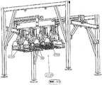
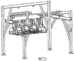
На этом участке пакеты пластин, ушки которых соединены мостами, вставляются в аккумуляторные ящики. При этом ПЕРВЫЙ, ВТОРОЙ и ТРЕТИЙ пакеты пластин принимаются первым параллельным перестановщиком и устанавливаются в аккумуляторные ящики (в отделения ОДИН, ТРИ и ПЯТЬ) для ячеек. С помощью второго параллельного перестановщика устанавливаются в повернутые вокруг вертикальной оси на 180° аккумуляторные ящики ЧЕТВЕРТЫЙ, ПЯТЫЙ и ШЕСТОЙ пакеты пластин в отделения ШЕСТЬ, ЧЕТЫРЕ и ДВА для ячеек. За счет этого достигается, как и предусмотрено в аккумуляторах, что на одной (продольной) стороне расположены соединенные мостами положительные ушки, а на другой (продольной) стороне - соединенные мостами отрицательные ушки, так что мосты можно соединять друг с другом в соответствии с полюсами через межъячеечные соединения, которые проходят через разделительные стенки между отделениями для ячеек аккумуляторных ящиков.In this section, plate packs whose ears are connected by bridges are inserted into battery boxes. In this case, the FIRST, SECOND and THIRD plate packs are received by the first parallel switcher and installed in battery boxes (in the ONE, THREE, and FIVE compartments) for the cells. Using the second parallel switcher, the FOURTH, FIFTH, and SIXTH packs of plates are inserted into the SIX, FOUR, and TWO cells for the cells in the battery boxes FOURTH, FIFTH, and SIXTH installed in 180 and rotated around the vertical axis. Due to this, it is achieved, as provided in the batteries, that positive ears connected by bridges are located on one (longitudinal) side, and negative ears connected by bridges on the other (longitudinal) side, so that the bridges can be connected to each other in accordance with the poles through intercellular connections that pass through the separation walls between the compartments for the cells of the battery boxes.
Захваты параллельных перестановщиков этого тринадцатого участка настроены так, что они могут принимать три пакета. Для этого захваты выполнены узкими и имеют два язычка, при этом один является подвижным, а другой неподвижным. Подвижный язычок перемещается вверх и снова вниз с помощью сдвигаемого вверх и вниз клина в зажимающее положение (обратное движение с помощью пружинной силы). Для приема одного пакета пластин три захвата вдвигаются в кассету, а именно сначала к первому, второму и третьему пакетам, при этом между неподвижными язычками захватов у пакета пластин зазор составляет около 5 мм. Затем они сдвигаются на 5 мм, так что неподвижные язычки прилегают к пакетам пластин. Затем перемещаются подвижные язычки, так что пакеты пластин зажимаются между язычками захватов. Для выравнивания пакетов пластин, которые удерживаются захватами, на расстоянии друг от друга, которое соответствует расстоянию отделений для ячеек в аккумуляторном ящике, два из трех захватов можно переставлять, а именно в соотношении 1:2, т.е. средний захват имеет наполовину большее перемещение сдвига, чем наружный захват, который лежит противоположно неподвижному захвату. Для ввода (аккумуляторных) пакетов пластин используются в качестве вспомогательных устройств воронкообразные устройства из стальных листов.The throttling concurrent captures of this thirteenth leg are configured so that they can receive three packets. To do this, the grips are made narrow and have two tabs, while one is movable and the other is motionless. The movable tongue moves up and down again with a wedge slid up and down to the clamping position (reverse movement by means of a spring force). To receive one package of plates, three grippers slide into the cartridge, namely, first to the first, second and third packages, while the gap between the fixed tongues of the grips of the plate package is about 5 mm. Then they are shifted by 5 mm, so that the stationary tabs are adjacent to the packages of plates. Then the movable tongues move, so that the packs of plates are clamped between the tongues of the grippers. To align the packages of plates that are held by the grippers at a distance from each other, which corresponds to the distance of the cell compartments in the battery box, two of the three grippers can be rearranged, namely in a 1: 2 ratio, i.e. the middle grip has half the shear displacement than the outer grip, which lies opposite to the stationary grip. For input (battery) packs of plates, funnel-shaped devices made of steel sheets are used as auxiliary devices.
Подъем аккумуляторного ящика при вставке ограничен по высоте ступенчатыми упорами, с целью учета различного размера пластин.The rise of the battery box during insertion is limited in height by step stops, in order to take into account the different size of the plates.
Для поворота аккумуляторного ящика на 180° (вокруг вертикальной оси) часть (роликового) транспортера можно поднимать и поворачивать на 180°.To rotate the
ЧЕТЫРНАДЦАТЫЙ УЧАСТОК:FOURTEENTH SECTION:
Угловой перестановщик.Corner switcher.
ПЯТНАДЦАТЫЙ УЧАСТОК:FIFTEEN SECTION:
Система обратной транспортировки кассет с интегрированными подъемниками непрерывного действия для автоматической замены кассет (для аккумуляторов легковых автомобилей и аккумуляторов грузовых автомобилей).Cassette reverse transport system with integrated continuous lifts for automatic cassette replacement (for passenger car batteries and truck batteries).
ШЕСТНАДЦАТЫЙ УЧАСТОК:SIXTEENTH SECTION:
Угловой перестановщик.Corner switcher.
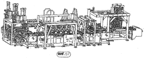
Затем снова следует первый участок (вариант выполнения согласно фиг.4-52).Then, the first section follows again (embodiment according to FIGS. 4-52).
В альтернативном варианте выполнения установки, с помощью которой может быть реализован способ согласно изобретению, установка (вариант выполнения согласно фиг.56-119) имеет следующие участки.In an alternative embodiment of the installation, with which the method according to the invention can be implemented, the installation (embodiment according to FIGS. 56-119) has the following sections.
ПЕРВЫЙ УЧАСТОК:FIRST PLOT:
Участок загрузки, в котором кассеты загружаются пакетами пластин.The loading area in which the cartridges are loaded with plate packs.
ВТОРОЙ УЧАСТОК:SECOND STATION:
Первый угловой перестановщик.The first corner switcher.
ТРЕТИЙ УЧАСТОК:THIRD PART:
Буферный участок.Buffer section.
ЧЕТВЕРТЫЙ УЧАСТОК:FOURTH SECTION:
Следующий за буферным участком участок, на котором выравниваются пластины и ушки.The section following the buffer section where the plates and ears are aligned.
ПЯТЫЙ УЧАСТОК:FIFTH SECTION:
Участок, на котором наружные ушки отгибаются внутрь.The area in which the outer ears are folded inward.
ШЕСТОЙ УЧАСТОК:SIXTH SECTION:
На этом участке кассеты с установленными в них и зажатыми пакетами пластин поворачиваются так, что ушки направлены вниз.In this section, the cassettes with the plates installed in them and clamped are turned so that the ears are directed downward.
СЕДЬМОЙ УЧАСТОК:SEVENTH SECTION:
Участок для очистки ушек щетками в качестве подготовки для прилива мостов и полюсных цапф.Brush cleaning area for ears to prepare for the tide of bridges and pole pins.
ВОСЬМОЙ УЧАСТОК:EIGHTH SECTION:
Участок, на котором ушки обрабатываются флюсом для облегчения прилива мостов и полюсных цапф.The area in which the ears are treated with flux to facilitate the flow of bridges and pole pins.
ДЕВЯТЫЙ УЧАСТОК:NINTH SECTION:
Буферный участок.Buffer section.
ДЕСЯТЫЙ УЧАСТОК:TENTH SECTION:
Два литейных участка для прилива мостов и полюсных цапф.Two foundries for the tide of bridges and pole pins.
ОДИННАДЦАТЫЙ УЧАСТОК:ELEVENTH PLOT:
Буферный участок.Buffer section.
ДВЕНАДЦАТЫЙ УЧАСТОК:TWELVE SECTION:
Участок, на котором полюсные цапфы и мосты обрабатываются щетками для очистки и для удаления облоя.The area in which the pole trunnions and bridges are treated with brushes for cleaning and for removing burr.
ТРИНАДЦАТЫЙ УЧАСТОК:THIRTEENTH PLOT:
Участок, на котором кассеты с установленными в них пакетами пластин снова поворачиваются так, что ушки и прилитые мосты направлены вверх.The area in which the cassettes with the plate packs installed in them are rotated again so that the ears and tidal bridges are directed upwards.
ЧЕТЫРНАДЦАТЫЙ УЧАСТОК:FOURTEENTH SECTION:
Буферный участок с другим угловым перестановщиком.Buffer section with another angle switcher.
ПЯТНАДЦАТЫЙ УЧАСТОК:FIFTEEN SECTION:
Разгрузочный участок, на котором транспортируемые в кассетах пластины вставляются в отделения подаваемых аккумуляторных ящиков.The unloading section, on which the plates transported in cassettes are inserted into the compartments of the supplied battery boxes.
ШЕСТНАДЦАТЫЙ УЧАСТОК:SIXTEENTH SECTION:
После разгрузочного участка угловой перестановщик для пустых кассет для их перестановки перемещают на участок обратной транспортировки.After the unloading section, the angular switcher for empty cartridges is moved to the reverse transport section to rearrange them.
СЕМНАДЦАТЫЙ УЧАСТОК:Seventeenth Section:
Другой угловой перестановщик, с помощью которого кассеты снова перемещаются в ПЕРВЫЙ УЧАСТОК (участок загрузки).Another corner switcher, with which the cartridges are again moved to the FIRST AREA (loading area).
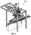
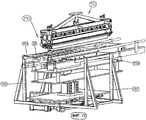
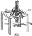
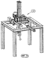
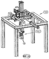
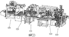
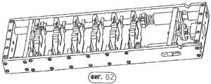
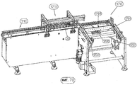
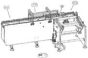
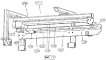
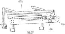
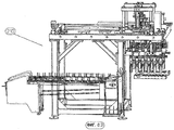
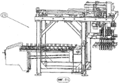
Другие подробности, признаки и преимущества изобретения следуют из приведенного ниже описания примеров выполнения установки согласно изобретению со ссылками на чертежи, на которых изображено:Other details, features and advantages of the invention follow from the following description of examples of the installation according to the invention with reference to the drawings, in which:
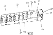
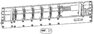
фиг.1-3 - кассеты, используемые для транспортировки аккумуляторных пластин в установке;1-3 - cassettes used for transporting battery plates in the installation;
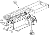
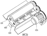
фиг.4-7 - установка под различными углами зрения;4-7 - installation from different angles;
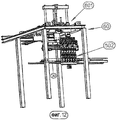
фиг.8-12 - участок для вставки пакетов пластин в кассеты;Figs. 8-12 show a section for inserting plate packs into cassettes;
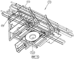
фиг.13-16 - участок для выравнивания пластин и ушек;Fig.13-16 - plot for aligning the plates and ears;
фиг.17-19 - угловой перестановщик;Fig.17-19 - angular permutation;
фиг.20-22 - участок для отгибания ушек;Fig. 20-22 is a section for bending ears;
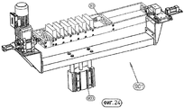
фиг.23-24 - участок для поворота кассет;Fig.23-24 - plot for rotation of the cassettes;
фиг.25-26 - участок для очистки щетками ушек аккумуляторных пластин;Fig.25-26 - plot for cleaning the brushes of the ears of the battery plates;
фиг.27-28 - участок для обработки флюсом;Fig.27-28 - plot for processing flux;
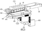
фиг.29-31 - участок для прилива мостов, межъячеечных соединений и полюсных цапф;Fig.29-31 - plot for the tide of bridges, intercellular connections and pole pins;
фиг.32-34 - угловой перестановщик;Figs. 32-34 show an angular permutation;
фиг.35-43 - параллельные перестановщики на участке загрузки и участке разгрузки;Fig.35-43 - parallel permutators on the loading section and the discharge section;
фиг.44-49 - захват параллельных перестановщиков;Fig.44-49 - capture parallel permutators;
фиг.50 и 51 - транспортер для аккумуляторных ящиков;Fig. 50 and 51 - conveyor for battery boxes;
фиг.52 - накопитель в виде подъемника непрерывного действия;Fig - drive in the form of a continuous lift;
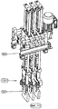
фиг.53 - пакет пластин;Fig - package of plates;
фиг.54 - пакет пластин с прилитыми к ушкам мостами с фланцами для межъячеечных соединений;Fig. 54 is a package of plates with bridges fitted to the ears with flanges for intercellular connections;
фиг.55 - аккумуляторный ящик с расположенными в нем пакетами пластин;55 is a battery box with plate packs disposed therein;
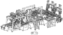
фиг.56-59 - другой вариант выполнения всей установки, в различных изометрических проекциях;Fig.56-59 is another embodiment of the entire installation, in various isometric projections;
фиг.60-64 - другой вариант выполнения кассеты с регулируемой пружинной силой;Fig. 60-64 is another embodiment of a cartridge with adjustable spring force;
фиг.65 - другой вариант выполнения щетки для ушек с регулируемой высотой щетки;Fig - another embodiment of a brush for ears with adjustable brush height;
фиг.66 и 67 - устройство для регулирования пружинной силы показанной на фиг.60-64 кассеты;Figures 66 and 67 show a device for adjusting the spring force of the cartridge shown in Figures 60-64;
фиг.68 и 69 - подъемный стол на конце отрезка обратной транспортировки;Fig and 69 - lifting table at the end of the section of the return transportation;
фиг.70-73 - угловой перестановщик на конце отрезка обратной транспортировки;Figs. 70-73 show an angular switcher at the end of a return transport segment;
фиг.74-76 - устройство для открывания кассет с помощью шпиндельной подъемной передачи;Fig.74-76 - a device for opening cassettes using a spindle lifting gear;
фиг.77-79 - стол для удержания пластин для загрузки и разгрузки кассет со сменными переходными плитами различной высоты;Fig.77-79 - table for holding plates for loading and unloading cassettes with removable adapter plates of various heights;
фиг.80-84 - участок для подачи пластин в кассеты;Figs. 80-84 show a section for feeding plates to cassettes;
фиг.85 и 86 - поворотный угловой перестановщик с непрерывным направлением транспортировки;Fig and 86 - rotary angular switcher with a continuous direction of transportation;
фиг.87 и 88 - поворотный угловой перестановщик с противоположным изменением направления транспортировки;Fig and 88 - rotary angular switcher with the opposite change in the direction of transportation;
фиг.89-92 - устройство для транспортировки аккумуляторных ящиков, включая приспособления для остановки аккумуляторных ящиков и вспомогательные устройства для вставки аккумуляторных пластин;Fig.89-92 - a device for transporting battery boxes, including devices for stopping battery boxes and auxiliary devices for inserting battery plates;
фиг.93-97 - предусмотренный в области участка прилива портальный перестановщик с захватами для захватывания кассет с аккумуляторными пластинами;Figs. 93-97 — a portal switcher with grippers for gripping cassettes with battery plates provided for in the region of the tide region;
фиг.98-102 - угловой перестановщик в начале отрезка обратной транспортировки, в различных проекциях;Fig.98-102 - angular permutation at the beginning of the segment of the return transportation, in various projections;
фиг.103-105 - участок прилива, в различных проекциях;103-105 - plot of the tide, in various projections;
фиг.106-112 - участок для извлечения аккумуляторных пластин из кассет и для установки аккумуляторных пластин в аккумуляторные ящики;106-112 is a section for removing battery plates from cassettes and for installing battery plates in battery boxes;
фиг.113-116 - стол для удержания пластин на участке разгрузки и113-116 - table for holding plates on the discharge area and
фиг.117-119 - щетка для очистки после операции прилива.Fig.11-119 - brush for cleaning after the operation of the tide.
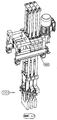
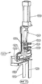
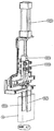
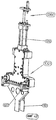
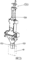
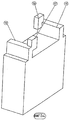
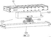
На фиг.53 схематично показан пакет 10 из аккумуляторных пластин - попеременно из положительных и отрицательных пластин, при этом в области одной (передней) узкой стороны расположены ушки 12 положительных пластин, а в задней на фиг.53 области - ушки 14 отрицательных пластин. Как указывалось выше, либо отрицательные, либо положительные пластины устанавливаются в карманы из сепараторного материала.On Fig schematically shows a package of 10 battery plates - alternately from the positive and negative plates, while in the area of one (front) narrow side are the
Ушки 12 положительных пластин соединяют друг с другом с помощью моста 16. Ушки 14 отрицательных пластин также соединяют друг с другом с помощью приливаемого моста 18. На фиг.54 дополнительно показано, что на мостах 16 и 18, которые соединяют друг с другом ушки 12, 14 отрицательных и положительных пластин, предусмотрены выступающие вверх фланцы 17, 19, которые служат для соединения пакетов пластин, которые находятся в смежных ячейках 22 аккумуляторного ящика 20, с помощью межъячеечного соединения 24.The
В кассетах 30, которые применяются для транспортировки пакетов 10 пластин через различные участки установки согласно изобретению, пакеты 10 пластин расположены так, что на одной продольной стороне кассет 30 расположены исключительно ушки 12 положительных пластин, а на другой продольной стороне - ушки 14 отрицательных пластин.In the
Однако в аккумуляторе пакеты 10 пластин расположены с попеременной ориентацией, как показано на фиг. 55. На фиг.55 показано также, как могут быть расположены фланцы 17, 19 для межъячеечного соединения 24, с одной стороны, и цапфы 11, 13 для изготовления полюсных цапф готового аккумулятора/батареи, с другой стороны.However, in the battery packs of
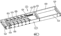
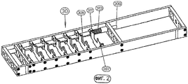
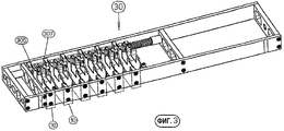
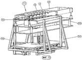
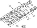
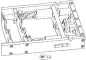
На фиг.1-3 показана кассета 30 согласно первому варианту выполнения, используемая в установке согласно изобретению, для транспортировки положительных и отрицательных объединенных в пакеты 10 аккумуляторных пластин от участка к участку.1-3 show a
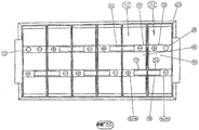
Кассета 30 имеет раму 301, которая имеет по существу прямоугольную форму. В раме 301 предусмотрено несколько соединенных с продольными стенками 303 рамы 301 и расположенных неподвижно в раме 301 промежуточных стенок 305. Кроме того, в раме 301 предусмотрены подвижные стенки 307, которые закреплены, по меньшей мере, на одной толкающей штанге 309, но предпочтительно на двух толкающих штангах (на фиг.1-3 показана лишь одна толкающая штанга 309), которые установлены с возможностью перемещения в продольном направлении. В раме 301 предпочтительно предусмотрены две установленные параллельно продольным стенкам 303 рамы 301 толкающие штанги 309. На толкающих штангах 309 удерживаются подвижные стенки 307 через крепежные блоки 311, которые закреплены на толкающих штангах 309 и соединены с подвижными стенками 307.The
На толкающие штанги 309 насажены винтовые пружины 313 сжатия, которые через гильзу 315 опираются на закрепленную в раме 301 поперечную стенку 317. За счет давления на противоположные пружинам 313 концы обеих толкающих штанг 309 можно сдвигать стенки 307 со сжатием пружин 313 из показанного на фиг.1 положения (закрытая кассета) в показанное на фиг.2 положение (открытая кассета). В положении «открытая кассета» между каждой неподвижной промежуточной стенкой 305 и относящейся к ней подвижной стенкой 307 предусмотрено свободное пространство, которое имеет ширину, превышающую толщину подлежащего вставке в кассету 30 и зажиманию в кассете 30 пакета 10 пластин. На фиг.3 показано, как пакеты 10 пластин (показаны штриховыми линиями на фиг.3) фиксируются посредством зажимания в кассете 30 между неподвижными относительно рамы промежуточными стенками 305 и подвижными стенками 307.Compression coil springs 313 are mounted on the
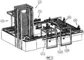
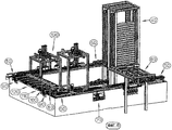
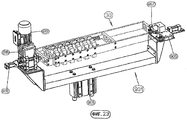
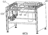
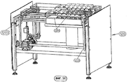
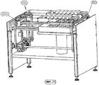
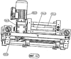
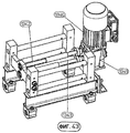
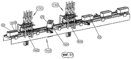
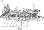
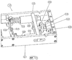
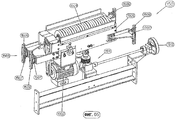
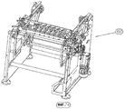
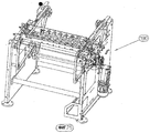
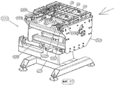
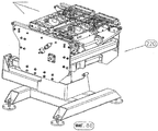
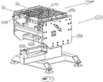
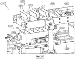
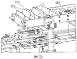
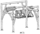
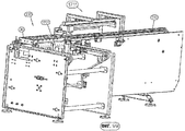
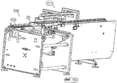
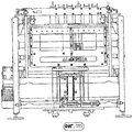
Показанная на фиг.4-7 в изометрической проекции с разных сторон вся установка согласно первому варианту выполнения изобретения, в которой может осуществляться способ согласно изобретению, состоит из следующих компонентов (участков):Shown in Figures 4-7 in isometric view from different sides, the entire installation according to the first embodiment of the invention, in which the method according to the invention can be carried out, consists of the following components (sections):
- выполненный в виде подъемника непрерывного действия накопитель 40 (пятнадцатый участок) для кассет, при этом предпочтительно предусмотрено два подъемника непрерывного действия для различных кассет 30;- made in the form of a continuous lift drive 40 (fifteenth section) for cassettes, while preferably there are two continuous lifts for
- первый участок 50 углового перестановщика - шестнадцатый участок, на котором подаваемые из подъемника непрерывного действия кассеты (они перемещаются поперек своей продольной протяженности) переводятся из первого направления движения в примыкающее к нему под углом 90° второе направление движения (кассеты перемещаются теперь в направлении своей продольной протяженности);- the
- участок 60 (первый участок) для загрузки кассет пакетами аккумуляторных пластин;- section 60 (first section) for loading cassettes with packages of battery plates;
- участок 70 (второй участок) для выравнивания пластин и ушек в кассетах;- section 70 (second section) for aligning the plates and ears in the cassettes;
- второй участок 50 углового перестановщика на конце первого отрезка траектории движения (третий участок, угловой перестановщик);- the
- участок 80 (четвертый участок) для отгибания наружных ушек аккумуляторных пластин на втором отрезке траектории движения;- section 80 (fourth section) for bending the outer ears of the battery plates on the second segment of the motion path;
- участок 90 (пятый участок) для поворота кассет на 180° вокруг их продольного направления;- section 90 (fifth section) for rotation of the
- участок 100 (шестой участок) для очистки ушек щетками;- section 100 (sixth section) for cleaning the ears with brushes;
- участок 110 (седьмой участок) для обработки ушек флюсом (флюсования);- section 110 (seventh section) for processing the ears with flux (fluxing);
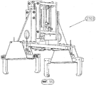
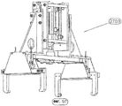
- участок 120 (девятый участок) для прилива мостов с межъячеечными соединениями и полюсными цапфами;- section 120 (ninth section) for the tide of bridges with intercellular connections and pole pins;
- другой участок 90 (одиннадцатый участок) для поворота кассет вокруг их продольного направления;- another section 90 (eleventh section) for turning the cartridges around their longitudinal direction;
- другой угловой перестановщик 50 (двенадцатый участок) на конце второго отрезка траектории движения;- another angular permutation 50 (twelfth section) at the end of the second segment of the trajectory of movement;
- на третьем отрезке траектории движения участок 130 (тринадцатый участок) для извлечения пакетов 10 пластин (положительных пластин, с одной стороны, и отрицательных пластин, с другой стороны) из кассет 30 и для вставки пакетов пластин в аккумуляторные ящики 20;- on the third segment of the trajectory, section 130 (thirteenth section) for removing packages of 10 plates (positive plates, on the one hand, and negative plates, on the other hand) from
- в конце этого отрезка траектории движения другой угловой перестановщик 50 (четырнадцатый участок), в котором пустые кассеты перемещаются в накопительные башни (пятнадцатый участок, подъемник непрерывного действия).- at the end of this segment of the trajectory of movement, another angular switcher 50 (fourteenth section), in which empty cartridges are moved to storage towers (fifteenth section, continuous lift).
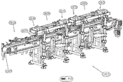
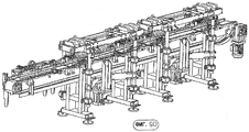
Через всю установку проходит траектория движения для кассет 30. Траектория движения состоит из четырех отрезков, которые расположены друг к другу под углом 90°, при этом в каждом углу траектории движения предусмотрены угловые перестановщики 50, которые передают (переставляют) кассеты 30 на соответствующий следующий отрезок траектории движения.A trajectory of movement for the
Ниже приводится описание отдельных участков установки (фиг.4-52) и выполняемых в них рабочих процессов.The following is a description of the individual sections of the installation (FIGS. 4-52) and the work processes performed therein.
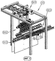
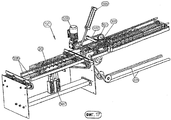
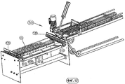
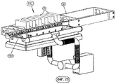
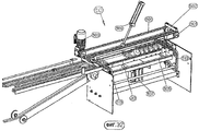
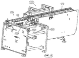
Предусмотренный на первом отрезке траектории движения участок 60 (первый участок) для вставки пакетов 10 пластин в кассеты 30 показан на фиг.8-12 в различных рабочих положениях и проекциях и имеет манипулятор 601.The section 60 (the first section) provided for in the first segment of the motion path for inserting the packs of 10 plates into the
Манипулятор 601 имеет подвижные вокруг нескольких осей захваты 602 для приема подаваемых на транспортерах 603 пакетов 10 пластин. Захваты 602 вводят принимаемые ими пакеты 10 пластин в подаваемые на первом отрезке траектории движения кассеты 30.The
Каждый захват 602 снабжен двумя выполненными в виде вилок захватными элементами, которые снаружи прикладываются к пакету 10 из аккумуляторных пластин и удерживают его посредством зажимания.Each
Например, применяемые на участке 60 для загрузки кассет 30 аккумуляторными пластинами захваты 602 имеют конструкцию, описание которой будет приведено ниже для захватов 1301 тринадцатого участка 130 для извлечения пакетов 10 аккумуляторных пластин из кассет 30 и для вставки их в аккумуляторные ящики 20, на основе фиг.44-47. В качестве альтернативного решения могут быть предусмотрены также другие захваты, например поворотные захваты.For example, the
Пакеты 10 пластин, состоящие каждый из соответствующего количества положительных и отрицательных аккумуляторных пластин, из которых или отрицательные, или положительные аккумуляторные пластины устанавливаются в карманы из сепараторного материала, вставляются в кассеты 30 так, что около одной продольной стенки 303 рамы 301 кассеты 30 расположены лишь ушки 12 положительных пластин, а около противоположной продольной стенки - исключительно ушки 14 отрицательных пластин. Это является предпочтительным для прилива мостов 16 и 18, которые соединяют друг с другом положительные или, соответственно, отрицательные ушки.Packs of 10 plates, each consisting of a corresponding number of positive and negative battery plates, of which either negative or positive battery plates are installed in pockets of separator material, are inserted into
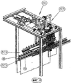
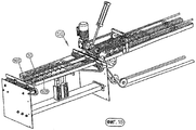
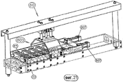
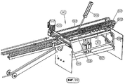
Загруженные пакетами 10 аккумуляторных пластин кассеты 30 направляются вдоль первого отрезка траектории движения к участку 70 (второй участок), на котором пластины и ушки пластин выравниваются (см. фиг.13-16).
На этом участке 70 подвижные стенки 307 кассеты 30 переставляются посредством приведения в действие толкающих штанг 309 так, что аккумуляторные пластины пакетов 10 являются подвижными относительно друг друга. Сначала на этом участке 70 пластины выравниваются, для чего на этом участке 70 предусмотрены две выравнивающие планки 701, 703, которые, как показано, в частности, на фиг.13 и 15, соприкасаются с выступающими внизу за раму 301 кассеты областями пластин, а именно с противоположных сторон. Для этого выравнивающие планки 701, 703 смонтированы на рамах 705, 707, которые с помощью привода 709 с косозубым зубчатым колесом и зубчатой рейкой (см. фиг.14) можно симметрично сближать друг с другом или, соответственно, удалять друг от друга.In this
Для выравнивания ушек над кассетами предусмотрено образованное наклонно установленными планками 711 устройство 713 выравнивания ушек. Это устройство 713 выравнивания ушек имеет две пары планок 711, которые установлены с возможностью поворота в держателях 715. Вал 717, который несет две наружные планки 711 каждой пары, через рычаг 719 связан с гидравлическим или пневматическим двигателем 721 так, что они могут поворачиваться. Для обеспечения синхронного движения второй планки 711 каждой пары валы 717 наружных пар планок снабжены зубчатым колесом, которое находится в зацеплении с зубчатым колесом, которое закреплено на валу соответствующей внутренней планки 711 (см. фиг.16).For alignment of the ears over the cassettes, a
После выравнивания пластин в кассете 30 на участке 70 посредством приведения в действие выравнивающих планок 701, 703 для пластин всех пакетов 10 и выравнивающих планок 711 для ушек 12, 14 снова приводятся в действие подвижные стенки 307 кассеты 30 посредством снятия давления с толкающих штанг 309, которые несут подвижные стенки 307. Пружины сжатия 313 прижимают подвижные стенки 307 с зажиманием пакетов 10 пластин снова к промежуточным стенкам 305.After aligning the plates in the
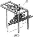
Показанный на фиг.17-19 угловой перестановщик 50 служит для перестановки загруженных пакетами 10 из аккумуляторных пластин кассет 30 с первого отрезка траектории движения на расположенный перпендикулярно ему второй отрезок траектории движения. При этом кассеты 30 на первом отрезке траектории движения перемещаются параллельно своему продольному направлению, в то время как на втором отрезке траектории движения они перемещаются поперек своего продольного направления от участка к участку второго отрезка.The
Угловой перестановщик 50 имеет в конце первого отрезка траектории движения над траекторией движения или, соответственно, над средствами транспортировки (лентами) две бесконечные ленты 501 (или конвейерные цепи), которые приводятся в движение двигателем 503 для сдвигания кассет 30 от первого отрезка траектории движения на направляющие 505 скольжения, которые расположены в начале второго отрезка траектории движения. Дополнительно к этому установлено два бесконечных ремня 501, которые снабжены, по меньшей мере, одной захватной планкой 502, с возможностью поворота с помощью гидравлического или пневматического двигателя 509. Направляющие 505 поднимаются и опускаются с помощью, по меньшей мере, одного гидравлического или пневматического двигателя 507.The
В первой стадии при перестановке кассеты 30 с первого отрезка траектории движения на второй отрезок траектории движения передняя область кассеты 30 уже надвинута на направляющие 505, в то время как задняя часть еще зажата между средствами 511 транспортировки первого отрезка и расположенными над ними средствами 501 транспортировки и сдвигается дальше с помощью захватной планки 502.In the first stage, when the
На фиг.18 кассета 30 расположена полностью на направляющих 505. Они опускаются вниз (см. фиг.19), так что кассета 30 своими концами расположена на конвейерных лентах 513 второго отрезка траектории движения. Рядом с обеими конвейерными лентами 513 предусмотрены направляющие стальные листы 515, сопряженные с концами (узких сторон) кассет 30.In Fig. 18, the
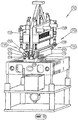
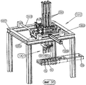
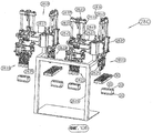
В качестве первого участка (четвертого участка) на втором отрезке траектории движения предусмотрен участок 80 для сгибания соответствующих самых наружных ушек каждого пакета 10 пластин (см. фиг.20-22). Этот участок 80 имеет мост 801 над вторым отрезком траектории движения, на котором предусмотрено поднимаемое и опускаемое устройство 803 для сгибания ушек. Устройство 803 для сгибания ушек имеет показанную детально на фиг.22 раму 805 с приводимыми в действие рабочими (гидравлическими или пневматическими) цилиндрами 807 через толкающие штанги 809 сгибающими плитами 811. Сгибающие плиты 811 расположены парами и отжимают при использовании устройства 803 самые наружные ушки каждого пакета 10 пластин внутрь, так что они устанавливаются наклонно под заданным углом. При этом ушки устанавливаются с наклоном внутрь к середине пакета 10 пластин.As the first section (fourth section), a
На фиг.20 показано сгибающее устройство 803 в положении готовности, а на фиг.21 показано сгибающее устройство 803 в рабочем положении, т.е. когда сгибаются ушки. При этом предусмотрено, что сгибающее устройство 803 своей рамой 805 опускается на пластины в кассете 30, а затем сгибающие плиты 811 приводятся в действие с помощью рабочих (гидравлических или пневматических) цилиндров 807 для сгибания самых наружных ушек каждого пакета 10 пластин.FIG. 20 shows a
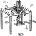
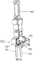
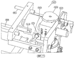
Кассеты 30 с отогнутыми внутрь самыми наружными ушками каждого пакета 10 пластины перемещаются на участок 90 (пятый участок), на котором кассеты 30 поворачиваются на 180° вокруг своей продольной оси, так что ушки 12, 14 направлены вниз. Этот участок 90 показан на фиг.23 и 24. Поворотное устройство участка 90 имеет выполненное в виде скобы основное тело 901, которое поднимается и опускается с помощью рабочего (гидравлического или пневматического) цилиндра 903. На одном конце основного тела 901 предусмотрен перемещаемый на каретке 905 конус 907, который входит в соответствующую выемку 321 в одной поперечной стенке кассеты 30. На другом конце основного тела 901 предусмотрен приводимый в действие с помощью рабочего (гидравлического или пневматического) цилиндра 909 конус 911, который входит в выемку 323 на другом конце кассеты 30. Этот конус 911 можно поворачивать с помощью двигателя 913, так что кассету 30 можно поворачивать из показанного на фиг.23 положения вокруг ее продольного направления в показанное на фиг.24 положение. Теперь ушки 12, 14 аккумуляторных пластин, которые зажаты в кассете 30, направлены вниз. В альтернативном варианте выполнения 90 можно сдвигать не только конус 911, но и весь блок из конуса 911, двигателя 913 и передачи 915 с помощью гидравлического или пневматического двигателя 909 с целью перемещения конуса 911 в отверстие 323 кассеты 30 и, соответственно, из него.
Кассеты 30 с направленными вниз ушками 12, 14 транспортируются на участок 100 (шестой участок), на котором ушки очищаются с помощью щеток, если это необходимо. Этот участок 100 для очистки ушек щетками (см. фиг.25-26) имеет установленные в раме 1003 с возможностью вращения (металлические) круглые щетки 1001, которые приводятся во вращение в противоположных направлениях с помощью приводного двигателя 1006. Кассеты 30 с удерживаемыми в них аккумуляторными пластинами просто транспортируются по второму отрезку траектории движения через этот щеточный участок 100, при этом ушки 12, 14 до блеска очищаются щетками.
Участок 100 с обеими проволочными щетками 1001 для очистки ушек 12, 14 показан на фиг.25 и 26, при этом на фиг.26 для ясности не изображен один щеточный валик 1001. Можно видеть, что на нижнем конце ванны 1005, над которой установлены с возможностью вращения щеточные валики 1001, предусмотрены прорези 1007, которые снабжены для отсасывания возникающей при обработке щетками ушек 12, 14 пыли отсасывающим устройством 1009.A
После участка для очистки щетками ушек 12, 14 предусмотрен участок 110 (седьмой участок), на котором очищенные щетками ушки 12, 14 аккумуляторных пластин обрабатываются флюсом. Пример выполнения участка 110 показан на фиг.27 и 28. Этот участок 110 имеет ванну 1101, в которой предусмотрено пропитанное флюсом пенопластовое тело 1102 (губка). Ванна 1101 с помощью поднимающего привода 1103 поднимается из своего положения готовности на расстоянии под находящейся на этом участке 110 кассеты 30 с аккумуляторными пластинами (см. фиг.27) в рабочее положение, в котором ушки 12, 14 аккумуляторных пластин вдавливаются в пропитанное флюсом пенопластовое тело 1102, для обработки ушек 12, 14 флюсом (см. фиг.28), и затем снова опускается. В ванне 1101 предусмотрено устройство для контроля уровня флюса. На обеих продольных сторонах ванны 1101 с пенопластовым телом 1103 с флюсом предусмотрены трубы 1105 с соплами 1107 для выдувания теплого воздуха с целью сушки ушек 12, 14 после обработки флюсом. Теплый воздух подается в трубы 1105 с соплами 1107 от вентилятора 1109 с нагревательным устройством 1111. Сушка ушек 12, 14 выполняется после перемещения ванны 1101 от кассеты 30 с пакетами 10 аккумуляторных пластин посредством опускания снова в показанное на фиг.27 положение.After the brushing portion of the
После участка 110 для флюсования ушек 12, 14 аккумуляторных пластин предусмотрен участок 120 (девятый участок), на котором к ушкам 12, 14 аккумуляторных пластин приливаются мосты 16, 18 с фланцами 17, 19 для межъячеечных соединений полюсных цапф 11, 13 (где это необходимо). Это устройство 120 показано на фиг.29-31.After
В показанном примере выполнения участок 120 для прилива мостов 16, 18 выполнен так, что удерживаемые в двух или трех кассетах 30 пакеты 10 пластин одновременно подаются в две или три литейные формы 1201. При этом предусмотрено, что литейные формы 1201 на участке 120 расположены неподвижно, а находящийся в области участка 120 (участка прилива) частичный отрезок 1203 второго отрезка траектории движения выполнен с возможностью поднимания и опускания с целью прилива мостов 16, 18, соединяющих ушки 12, 14 аккумуляторных пластин. Снабжение литейных форм 1201 для прилива мостов 16, 18 металлическим расплавом (расплавленным свинцовым сплавом), а также выполнение форм 1201 известно для специалистов в данной области техники и поэтому их подробное описание здесь не приводится.In the shown embodiment, the
После участка 120 для прилива мостов 16, 18, фланцев 17, 19 для межъячеечных соединений и полюсных цапф 11, 13 предусмотрен другой поворотный участок 90, на котором кассеты 30 снова поворачиваются так, что ушки 12, 14 аккумуляторных пластин вместе с прилитыми мостами 16, 18 и фланцами 17, 19, а также, при необходимости, полюсными цапфами 11, 13 снова обращены вверх.After
После участка 100 для обработки ушек флюсом (флюсование) и после участка 120 для прилива мостов в зависимости от величины установки предусмотрены один или два буферных отрезка. Эти буферные отрезки позволяют компенсировать различное время обработки на отдельных участках.After
В конце второго отрезка траектории движения снова предусмотрен перестановочный участок 50, который показан на фиг.32-34. Кассета 30, транспортируемая поперек своей продольной протяженности на втором отрезке траектории движения (конвейерных лентах 513), поднимается с помощью подъемных планок 505 с конвейерных лент 513 второго отрезка и с помощью расположенных над подъемными планками 505 конвейерных лент 501 (или (бесконечных) цепей с захватами 502 в качестве линейных осей), которые повернуты вниз в свое рабочее положение (цилиндры 509), транспортируется на третий отрезок траектории движения, на котором кассеты 30 перемещаются снова параллельно своему продольному направлению. При этом на фиг.32 показано, как кассета 30 приходит в конец второго отрезка траектории движения, на фиг.33 - поднятая подъемными планками 505 кассета 30 и на фиг.34 - как кассета 30 перестанавливается на следующий отрезок (третий отрезок) траектории движения, и уже следующая кассета 30 приходит к концу второго отрезка траектории движения.At the end of the second segment of the motion path, a
На этом третьем отрезке траектории движения кассеты 30 перемещаются к участку 130 (тринадцатому участку) для разгрузки кассет 30 и для вставки извлеченных из кассет 30 пакетов 10 пластин в аккумуляторные ящики 20.In this third section of the trajectory, the
Участок 130, также тринадцатый участок этого варианта выполнения установки согласно изобретению, разделен на два подучастка (в данном примере образованы параллельными перестановщиками), которые имеют, по существу, идентичную конструкцию и описание назначения, конструкции и функции которых приводится ниже со ссылками на фиг.35-51.
Параллельно этому отрезку траектории движения предусмотрен конвейер 140 (см. фиг.4, 50, 51) для транспортировки аккумуляторных ящиков 20, в которые должны вводиться пакеты 10 пластин с помощью захватов 1301 тринадцатого участка 130, как будет описано ниже. На конвейере 140 для аккумуляторных ящиков 20 предусмотрен участок 1401, на котором аккумуляторные ящики 20 поворачиваются вокруг вертикальной оси.A conveyor 140 (see FIGS. 4, 50, 51) is provided parallel to this segment of the motion path for transporting the
Основанием для предусматривания двух параллельных перестановщиков с тремя захватами 1301 каждый и между ними участка 1401 для поворота аккумуляторных ящиков 20 на 180° вокруг вертикальной оси является то, что на одной продольной стороне расположены исключительно ушки 12 положительных пластин, а на другой продольной стороне - ушки 14 отрицательных пластин. Основание для такого расположения было указано выше в связи с участком 120 для прилива мостов 16, 18 и т.д.The reason for the provision of two parallel permutators with three
Два параллельных перестановщика, соответственно, с тремя захватами 1301 тринадцатого участка 130 имеют идентичную конструкцию и их описание приведено ниже со ссылками на фиг.35-49.Two parallel permutators, respectively, with three
Каждый параллельный перестановщик имеет установленную на направляющих штангах 1303 с возможностью сдвига систему из (трех) захватов 1301 (например, в соответствии с вариантом выполнения, описание которого будет приведено ниже со ссылками на фиг 44-49). Захваты 1301 удерживаются с возможностью регулирования в каретке 1305, которая установлена с возможностью сдвига на направляющих штангах 1303 в раме 1307, так что можно изменять относительное расстояние захватов 1301 друг от друга. Для перемещения каретки 1305 поперек направления транспортировки этого отрезка траектории движения предусмотрен гидравлический или пневматический двигатель 1309. Для подъема и опускания захватов 1301 предусмотрены три других гидравлических или пневматических двигателя 1311.Each parallel switcher has a system of (three)
На фиг.35 показано, как кассета 30 находится в положении, в котором извлекается первая группа из трех содержащихся в ней пакетов 10 аккумуляторных пластин. Например, речь идет при этом о первом, втором и третьем пакетах 10 пластин. Для этого захваты 1301 опускаются из показанного на фиг.35 положения в показанное на фиг.36 положение, и закрываются захватные стальные листы 1321/1322, так что один пакет 10 пластин зажимается в каждом захвате 1301. Захваты 1301 с зажатыми в них пакетами 10 пластин затем поднимаются (см. фиг.37) и посредством приведения в действие каретки 1305 перемещаются поперек направления четвертого отрезка траектории движения, пока они не будут расположены над поданным с помощью конвейера 140 аккумуляторным ящиком 20. Затем захваты 1301 с пакетами 10 пластин снова опускаются (см. фиг.39).FIG. 35 shows how the
Прежде чем пакеты 10 пластин устанавливаются в аккумуляторные ящики 20 в соответствующие отделения 22 для ячеек (отделения 1, 3 и 5 для ячеек) за счет опускания захватов 1301 и поднимания аккумуляторного ящика 20, захваты 1301 перемещаются на соответствующее расстояние друг от друга.Before the
При этом в целом выполняются следующие движения:Moreover, in general, the following movements are performed:
Сначала захваты 1301 находятся в исходном положении: расстояние от захвата до захвата равно шагу кассеты 30; все захваты 1301 находятся в поднятом положении, как показано на фиг.35.First, the
Захваты 1301 опускаются в кассету 30 (фиг.36). Затем три захвата 1301 сдвигаются в боковом направлении (5 мм - перемещение сдвигающего цилиндра 1323 на фиг.42), чтобы неподвижные захватные стальные листы 1321 прилегали сбоку к пакетам 10 аккумуляторных пластин. Затем выполняется зажимание пакетов 10 с помощью соответствующего захвата 1301 за счет перемещения подвижных язычков 1322 (см. фиг.36). Затем захваты 1301 перемещаются вверх (см. фиг.37) и осуществляется параллельный сдвиг захватов 1301 относительно друг друга для согласования шага с шагом аккумуляторного ящика (с расстоянием между отделениями 22 для ячеек (см. фиг.38). Затем захваты 1301 опускаются вниз, и пакеты 10 аккумуляторных пластин устанавливаются в аккумуляторный ящик 20 (см. фиг.39), который для этого поднимается.The
Затем захваты 1301 перемещаются вверх, а аккумуляторный ящик 20 вниз, и происходит параллельное смещение захватов 1301 относительно кассеты 30. Во время этого параллельного смещения расстояние между захватами 1301 снова приводится в соответствие с шагом кассеты 30, и захваты 1301 сдвигаются в стороны (5 мм). Теперь захваты 1301 снова находятся в исходном положении.Then, the
Захваты 1301 второго параллельного перестановщика участка 130 работают, соответственно, для вставки остальных трех пакетов 10 из кассеты 30 в (еще пустые) отделения 22 аккумуляторного ящика 20.The
На фиг.40 и 41 показаны захваты 1301 (на виде сзади на фиг.35-39) с двумя различными шагами (расстояниями захватов 1301 друг от друга). Захваты 1301 можно с одинаковым шагом раздвигать или, соответственно, сдвигать. Это происходит с помощью двух ходовых винтов 1342, 1343 (см. фиг.42, 43) с различным шагом резьбы (один винт имеет двойной шаг другого винта), которые с помощью двигателя 1340 приводятся в движение через передачу 1341.FIGS. 40 and 41 show grippers 1301 (rear view of FIGS. 35-39) with two different steps (distances of
Ниже приводится описание конструкции захватов 1301 обоих параллельных перестановщиков тринадцатого участка 130 со ссылками на фиг.44-49. Каждый захват 1301 имеет неподвижный захватный язычок 1321 (захватный металлический лист) и второй сдвигаемый параллельно неподвижному язычку 1321 захватный язычок 1322. Захватный язычок 1322, который является подвижным, расположен на носителе 1323, который соединен с двумя направляющими штангами 1325, которые сдвигаются в основной плите 1327 захвата 1301. Направляющие штанги 1325 соединены в показанном примере выполнения с L-образными соединительными элементами 1329, которые установлены с возможностью сдвига на четырех направляющих цапфах 1331 на основной плите 1327. Соединительные элементы 1329 нагружены пружинами 1333, которые надеты на направляющие цапфы 1331, так что подвижный захватный язычок 1332 нагружается в направлении от неподвижного язычка 1321, т.е. в удаленное от него положение. Для закрывания захвата 1301, т.е. для перемещения подвижного захватного язычка 1322 к неподвижному захватному язычку 1321, предусмотрен приводимый в движение с помощью гидравлического или пневматического двигателя 1350 клин 1351, который сдвигается из показанного на фиг.45 положения (открытый захват) в показанное на фиг.47 положение (закрытый захват). В рабочем положении клин 1351 отжимает соединяющую соединительные элементы 1329 друг с другом плиту 1353 от основной плиты 1327 захвата 1301, так что подвижный захватный язычок 1322 перемещается к неподвижному, жестко соединенному с основной плитой 1327 захватному язычку 1321.The following is a description of the design of the
Как показано на фиг.48 и 49, предусмотрено еще одно - регулируемое - ограничение 1360 хода клина 1351.As shown in FIGS. 48 and 49, there is yet another — adjustable —
Указанная конструкция обеспечивает тонкое выполнение захватов 1301, так что они без проблем могут входить в кассету 30 для приема пакетов 10 аккумуляторных пластин и для вставки пакетов 10 аккумуляторных пластин в отделения 22 для ячеек аккумуляторных ящиков 20.This design provides a fine execution of the
На фиг.50 и 51 показано предусмотренное на тринадцатом участке 130 для вставки пакетов 10 пластин в аккумуляторные ящики 20 транспортировочное устройство 140 (рольганг) для аккумуляторных ящиков 20. На этом рольганге 140 аккумуляторные ящики 20 подаются к первому параллельному перестановщику для вставки пакетов 10 пластин в отделения 22 для ячеек («1», «3» и «5») для пакетов 10 аккумуляторных пластин, затем из этого положения к устройству 1401 для поворота аккумуляторных ящиков 20 и далее ко второму параллельному перестановщику для загрузки приемных пространств (отделений 22) для ячеек «2», «4» и «6» пакетами 10 пластин. Дополнительно к этому на фиг.50 показано, что аккумуляторные ящики 20 в процессе вставки пакетов 10 пластин в отделения 22 для ячеек в аккумуляторных ящиках 20 поднимаются с рольганга 1401 с помощью подъемных устройств 1402.50 and 51 show the transport device 140 (roll table) for
Кроме того, на фиг.50 показано, что для надежного введения пакетов 10 пластин над подъемными устройствами 1402 для аккумуляторных ящиков 20 предусмотрены воронкообразные направляющие стальные листы 1403, которые обеспечивают надежную вставку пакетов 10 пластин в отделения 22 для ячеек.In addition, FIG. 50 shows that to securely insert packs of 10 plates over
Снова пустые после извлечения пакетов 10 пластин кассеты 30 направляются с помощью другого углового перестановщика 50 на четвертый отрезок траектории движения и на нем далее к первому угловому перестановщику 50 в начале первого отрезка траектории движения. В (двух) накопителях 40, которые выполнены в виде подъемников непрерывного действия, кассеты 30 удерживаются в готовности к применению, при этом они из накопителей 40 перемещаются поперек своей продольной протяженности к первому отрезку траектории движения и к первому предусмотренному в начале этого отрезка угловому перестановщику 50, когда необходима смена кассет (для аккумуляторов легковых автомобилей или аккумуляторов грузовых автомобилей). Вертикальные накопители 40 хранят кассеты 30 и получают или отдают кассеты 30, когда требуются кассеты другой величины.Again empty after removing the
Показанный на фиг.56-59 в различных проекциях другой вариант выполнения установки для загрузки аккумуляторных ящиков пакетами 10 пластин содержит следующие участки:Shown in Fig.56-59 in various projections another embodiment of the installation for loading battery boxes packs of 10 plates contains the following sections:
- загрузочный участок 210 (см. фиг.80-84), в котором в кассеты 30 загружаются пакеты 10 пластин,- loading section 210 (see Fig. 80-84), in which packages of 10 plates are loaded into
- первый поворотный угловой перестановщик 220 (см. фиг.85 и 86),- the first rotary angle switcher 220 (see Figs. 85 and 86),
- после первого поворотного углового перестановщика 220 буферный участок,- after the first
- после буферного участка участок 70, в котором выравниваются пластины и ушки 12, 14 (см. фиг.13-16),- after the buffer section, a
- после этого участка 70 участок 80, в котором сгибаются наружные ушки 12, 14 (см. фиг.20-22),- after this
- после этого участка 80 для сгибания наружных ушек пластин участок 90, в котором кассеты поворачиваются, так что ушки 12, 14 направлены вниз (см. фиг.23 и 24),- after this
- затем участок 150 (см. фиг.65), в котором ушки 12, 14 очищаются щетками,- then the plot 150 (see Fig. 65), in which the
- затем следует участок 110 (см. фиг.27 и 28), в котором ушки обрабатываются флюсом для облегчения прилива мостов 16, 18 и полюсных цапф 11, 13,- then follows section 110 (see Figs. 27 and 28), in which the ears are treated with flux to facilitate the tide of
- затем буферный участок,- then the buffer section,
- после буферного участка два литейных участка 270 для прилива мостов 16, 18, фланцев 17, 19 для межъячеечных соединений и полюсных цапф 11, 13 (см. фиг.93-97 и фиг.103-105),- after the buffer section, two casting
- после участка 270, в котором приливаются мосты 16, 18, фланцы 17, 19 и полюсные цапфы 11, 13, буферный участок и- after
- после него участок 300 для очистки щетками мостов 16, 18 и полюсных цапф 11, 13 и для удаления облоя (см. фиг.117-119),- after it, a
- затем участок 90, в котором кассеты 30 снова поворачиваются так, что ушки 12, 14 и прилитые мосты 16, 18 направлены вверх (см. фиг.23 и 24),- then the
- затем другой буферный участок, за которым следует второй поворотный угловой перестановщик 230 (см. фиг.87, 88),- then another buffer section, followed by a second rotary angle switcher 230 (see Fig. 87, 88),
- после поворотного углового перестановщика 230 в установке предусмотрен разгрузочный участок 280, в котором транспортируемые в кассетах 30 пластины устанавливаются в отделения 22 аккумуляторных ящиков 20 (см. фиг.89-92),- after the
- после этого разгрузочного участка 280 угловой перестановщик (см. фиг.98-102) для пустых кассет 30 для их перестановки на участок обратной (возвратной) транспортировки и- after this
- после участка обратной транспортировки другой угловой перестановщик, с помощью которого кассеты 30 снова подаются в загрузочный участок 210, в котором они загружаются подаваемыми аккумуляторными пластинами, которые объединены в пакеты 10 (см. фиг.68-73).- after the reverse transportation section, another angular switcher, with which the
В показанном на фиг.60-64 в разных проекциях альтернативном варианте выполнения кассеты 30 для транспортировки пакетов 10 аккумуляторных пластин через установку учитывается то, что пакеты 10 пластин в зависимости от типа аккумулятора имеют различную толщину, но при этом необходимо всегда применять приблизительно одинаковую силу зажимания для удержания пластин без повреждений, но надежно в кассетах 30. Для этого предусмотрено, что в сдвигаемой в кассете 30 в ее продольном направлении стенке 331 закреплены гильзы 315, в которых установлены винтовые пружины 313 сжатия, которые нагружают толкающие штанги 309, на которых смонтированы регулируемые промежуточные стенки 307, для сдвигания к неподвижным промежуточным стенкам 305. На эту стенку 331 опирается с возможностью поворота диск 333, который несет штифты или цапфы 335 различной протяженности. Свободные концы штифтов 335 (противоположные подвижной стенке 331 концы штифтов 335) снабжены блоком 337, который закреплен на узкой поперечной стенке кассеты 30. За счет поворота диска 333 можно регулировать положение стенки 331 и тем самым предварительное напряжение пружин 313, которые нагружают подвижные стенки 307, в соответствии с толщиной пакетов 10 пластин. При этом предусмотрено, что для самых толстых пакетов 10 пластин выбирается самый короткий штифт 335 поворотного диска 333 (см. фиг.64), так что сдвигаемая стенка 331, которая несет гильзы 315 для пружин 313, меньше сдвигается в пространство кассеты 30, в котором пакеты 10 пластин зажимаются между промежуточными стенками 305 и 307.In the alternative projection shown in FIGS. 60-64 in different projections, the
В показанном на фиг.65 варианте выполнения участка 150 с одной щеткой 1501 для обработки ушек 12, 14 аккумуляторных пластин (щетка для ушек) предусмотрена единственная приводимая во вращение щетка 1501 для ушек, которая приводится в действие электродвигателем 1502. Блок 1503 из щетки 1501, ее опоры 1505 и электродвигателя 1502 расположен с возможностью регулирования по высоте, для чего он направляется в станине с помощью четырех направляющих башмаков 1507 на вертикальных направляющих планках 1509.In the embodiment shown in FIG. 65, a
Для регулирования высоты блока 1503 со щеткой 1501 для ушек предусмотрен шпиндельный привод 1511, который можно приводить в действие, например, с помощью рукоятки 1512.To adjust the height of the
На фиг.66 и 67 показано устройство 160, с помощью которого можно поворачивать предусмотренный в кассетах 30 диск 333 с имеющими различную длину, выполненными в виде штифтов 335 упорами для регулирования желаемой силы пружин 313, которые нагружают регулируемые промежуточные стенки 307 кассеты 30. При этом предусмотрен нажимной стержень 1601, который приводится в действие рабочим цилиндром 1602 (пневматическим), который воздействует посредине на диск 333, который опирается с возможностью поворота на промежуточную стенку 331 для подъема упоров 335 (штифтов) блока 337 к узкой концевой стенке кассеты 30. За счет поворота диска 333 можно выбирать упор 335, который необходим для желаемой силы пружины в зависимости от толщины пакетов 10 пластин. Поворот диска 333 с упорами 335 осуществляется, например, вручную, однако может выполняться также с помощью неизображенного привода. Устройство согласно фиг.66 и 67 можно комбинировать с линейным транспортером, с помощью которого кассеты перемещаются поперек своей продольной протяженности на бесконечных конвейерных лентах или цепях, которые проходят по направляющим роликам. Этот линейный транспортер предпочтительно является угловым перестановщиком, показанным на фиг.68-73, описание которого приводится ниже.Figures 66 and 67 show a
На фиг.68 и 69 показан угловой перестановщик (подъемный стол) 170, расположенный на конце отрезка 310 обратной транспортировки для пустых кассет 30, по которому пустые кассеты 30 транспортируются из разгрузочного участка 280 к загрузочному участку 210 в начале установки, т.е. к участку 210, в котором кассеты 30 снабжаются пакетами 10 пластин. При этом кассеты 30, приходящие справа на фиг.69, перемещаются на рольганг 1701 углового перестановщика 170. Рольганг 1701 опускается вместе со своим подъемным столом 1703 с помощью гидравлического или пневматического двигателя 1705, так что кассеты 30 лежат своими концами (узкими стенками) на транспортировочных цепях 1707 и могут транспортироваться ими далее к загрузочному участку 210. Для надежного направления кассет 30 на цепных транспортерах 1707 предусмотрены проходящие в продольном направлении направляющие 1709.FIGS. 68 and 69 show an angular switcher (lift table) 170 located at the end of the
На фиг.70-73 показан с другой стороны еще раз угловой перестановщик 170 согласно фиг.68 и 69 с сопряженным с ним концом отрезка 310 обратной транспортировки для пустых кассет 30. При этом также показано, что над концом отрезка 310 обратной транспортировки, на котором пустые кассеты 30 транспортируются в направлении их продольной протяженности, предусмотрено захватывающее сверху кассеты 30 сдвигающее устройство 1711 (см. фиг.72 и 73), которое переставляет кассеты 30 на поднятый подъемный стол 1703 углового перестановщика 170 согласно фиг.68 и 69 посредством сдвига. После опускания подъемного стола 1703 кассеты 30 транспортируются далее цепными транспортерами 1707 (см. фиг.68 и 69) до загрузочного участка 210, после установки, при необходимости, силы пружин 313 сжатия в кассетах 30 с применением устройства 160 согласно фиг.66 и 67.On Figs. 70-73, on the other hand, the
Сдвигающее устройство 1711, показанное в увеличенном масштабе на фиг.72 и 73, имеет установленную с возможностью поворота на сдвигаемой с помощью линейного привода 1713 (пневматического цилиндра) вдоль направляющих стержней 1715 каретке 1717 защелку 1719, которая при движении вперед воздействует на задний конец достигшей конца отрезка 310 обратной транспортировки кассеты 30. Защелка 1719 сопряжена с исполнительным рычагом 1721, который установленным на нем с возможностью вращения роликом 1723 входит в направляющую 1724. Направляющая 1724 с помощью проходящей в продольном направлении планки 1725 разделена на нижний направляющий шлиц 1727 и верхний направляющий шлиц 1729. На выходном конце сдвигающего устройства 1711 (справа на фиг.72) на проходящей в продольном направлении планке 1725 предусмотрена поворотная створка 1731. Эта створка 1731 приводит к тому, что она сначала перемещает движущийся в нижнем направляющем шлице 1727 направляющей 1725 ролик 1723 при обратном ходе створки 1731 в верхний направляющий шлиц 1729 (см. фиг.73), за счет чего сдвигающая защелка 1719 также поворачивается вверх, так что она при обратном ходе движется над подошедшей в это время кассетой 30. На заднем конце (слева на фиг.72) направляющих шлицов 1727/1729 ролик 1723 снова падает в нижний направляющий шлиц 1727, так что защелка 1719 также поворачивается вниз и готова для следующего процесса сдвига (показанное на фиг.72 положение).The
На фиг.74-76 показано устройство 190, с помощью которого можно перемещать подвижные промежуточные стенки 307 кассеты 30 относительно неподвижных промежуточных стенок 305 кассеты 30 («открывание» кассет), для увеличения расстояния между ними. Таким образом, можно вставлять пакеты 10 пластин без трения на промежуточных стенках 305, 307. Это устройство 190 содержит два штифта 1901, которые проходят через отверстия в противоположной пружинам 313 сжатия в кассете 30 концевой стенке. Штифты 1901 сдвигают несущие подвижные промежуточные стенки 307 стержни 309 со сжиманием пружин 313. Таким образом, увеличивается расстояние между каждой неподвижной промежуточной стенкой 305 и относящейся к ней подвижной промежуточной стенкой 307. Штифты 1901 приводятся в действие от электродвигателя через привод 1903 в виде ходового винта.On Fig-76 shows a
С помощью управляющей программы машины задается определенная ширина открывания кассеты 30. Этот путь можно задавать посредством подсчета поворотов связанного с приводом 1903 штифтов 1901 кулачкового диска 1905 с помощью счетного датчика 1907.Using the control program of the machine, a certain opening width of the
При закрывании кассеты 30 (отводе штифтов 1901 в их исходное положение) нулевая точка задается вновь с помощью опорной точки (точки начала отсчета) 1909 на опорном датчике 1911.When closing the cartridge 30 (retracting the
Такие устройства 190 для «открывания» кассет 30, т.е. для удаления подвижной промежуточной стенки 307 от соответствующей ей неподвижной промежуточной стенки 305, предусмотрены как на участке 210 для загрузки кассет пакетами 10 аккумуляторных пластин, так и на участке 70 для выравнивания ушек или, соответственно, пластин. Два таких устройства 190 предусмотрены также на разгрузочном участке 280, на котором пакеты 10 пластин извлекаются из кассет 30 и вводятся в аккумуляторные ящики 20.
На фиг.77-79 показан удерживающий пластины стол 320, который используется при загрузке кассет 30 пакетами 10 пластин. Выполненный соответствующим образом удерживающий пластины стол 320 может быть также предусмотрен на участке 280 для извлечения пакетов 10 пластин (разгрузочном участке). Удерживающий пластины стол 320 закреплен на основном носителе 3201 на машинной станине с возможностью переставления по высоте до упора с помощью подъемного привода 3203.On Fig-79 shows a plate holding table 320, which is used when loading
Поскольку пакеты 10 пластин вставляются в кассеты 30 с определенным выступанием ушек 12, 14, то пакеты 10 пластин в зависимости от высоты подлежащих вставке в кассеты 30 пластин выступают более или менее далеко вниз за кассеты 30. Для учета этих различий в удерживающем пластины столе 320 предусмотрены имеющие различную толщину переходные плиты 3205. Таким образом, существует возможность использования на удерживающем пластины столе 320 переходных плит 3205, толщина которых соответствует высоте подлежащих введению в кассеты 30 пластин, так что обеспечивается правильное выступание ушек 12, 14 на верхней стороне кассеты 30, необходимое для дальнейшей обработки. Описание дальнейших подробностей будет приведено ниже со ссылками на фиг.113-116.Since the packs of 10 plates are inserted into the
На фиг.80-84 показан участок 210 для загрузки кассет 30 пакетами 10 пластин в различных рабочих положениях.On Fig-84 shows a
Загрузочный участок 210 имеет две расположенные рядом друг с другом в раме 2101 группы по шесть захватов 2103, которые могут захватывать подаваемые по двум параллельным друг другу конвейерным лентам 2105 пакеты 10 из положительных и отрицательных аккумуляторных пластин и вставлять в подготовленные кассеты 30 (с «открытыми» промежуточными стенками, как показано на фиг.74-76). При этом на фиг.80 показана ситуация, в которой захваты 2103 расположены над пакетами 10 пластин, на фиг.81 захваты 2103 опущены вниз для приема с обеих конвейерных лент 2105 пакетов 10 пластин. На фиг.82 показана ситуация, в которой обе группы захватов (каждая с шестью захватами 2103) расположены в своем положении передачи над кассетами 30. На фиг.83 показана ситуация, где обе группы захватов 2103 расположены в своем исходном положении над кассетами 30. Наконец, на фиг.84 показана ситуация, в которой захваты 2103 опущены вниз для вставки пакетов 10 пластин в кассеты 30 так, что пакеты 10 пластин устанавливаются в пространства между неподвижными промежуточными стенками 305 и соответствующими им подвижными промежуточными стенками 307.The
Поскольку шаг образованных в кассетах 30 между неподвижными промежуточными стенками 305 и подвижными промежуточными стенками 307 приемными пространствами для пакетов 10 пластин отличается от расстояния между пакетами 10 пластин на обеих конвейерах 2105, с которых пакеты 10 пластин принимаются захватами 2103, то расстояние между захватами 2103 уменьшается перед опусканием в кассету 30, как показано для сравнения на фиг.83 и 84.Since the step of the receiving spaces for the packages of 10 plates formed in the
Снабженные пакетами 10 пластин кассеты 30 транспортируются поперек их продольной протяженности из загрузочного участка 210 к первому поворотному угловому перестановщику 220 (см. фиг.85, 86).
При вставке пакетов 10 пластин в кассеты 30 они находятся над подъемными столами 320 показанной на фиг.77-79 конструкции, при этом пластины перемещаются вниз до тех пор, пока их нижние горизонтальные кромки не будут располагаться сверху на установленной на подъемном столе 320 переходной плите 3205. После этого захваты 2103 отпускают пакеты 10 пластин, и кассеты 30 закрываются посредством перемещения подвижных промежуточных стенок 307 под действием винтовых пружин 313 сжатия к соответствующим неподвижным промежуточным стенкам 305 с зажиманием пакетов 10 пластин.When inserting packages of 10 plates into
Указанный выше первый поворотный угловой перестановщик 220 показан на фиг.85 и 86. Поворотный угловой перестановщик со «сквозным транспортирующим движением» имеет рамную конструкцию 2201, в которой проходят по направляющим роликам 2207 две бесконечные транспортировочные цепи 2203, приводимые в движение двигателем 2205. На этих цепях 2203, а именно на их верхних горизонтальных ветвях, подаются кассеты 30 (справа на фиг.85), пока, например, передние две кассеты 30 не придут в соприкосновение с выступающими из траектории движения кассет 30 упорами 2209. Эти упоры 2209 выполнены с возможностью опускания, когда кассеты 30 подлежат дальнейшей транспортировке. Вся рамная конструкция 2201 поворотного углового перестановщика 220 согласно показанному на фиг.85 и 86 варианту выполнения установлена с возможностью поворота на основной раме 2211, при этом для осуществления поворотного движения (на 90°) в показанном примере выполнения может быть предусмотрен рабочий цилиндр (пневматический цилиндр).The aforementioned first
Как только две кассеты 30 попадают на поворотный угловой перестановщик 220 согласно фиг.85 и 86 (положение на фиг.85) и передняя кассета 30 приходит в соприкосновение с упорами 2209, приводится в действие пневматический цилиндр 2213 и поворотный угловой перестановщик 220 поворачивается в показанное на фиг.86 положение. После опускания упоров 2209 обе кассеты 30 без реверсирования направления движения транспортировочных цепей 2203 («непрерывное транспортирующее движение») транспортируются дальше в расположенный после первого поворотного перестановщика 220 буферный участок, соответственно, к первому участку 70 обработки (выравнивание ушек и пластин).As soon as two
На фиг.93-97 показаны захватные системы 2701, которые можно применять на литейном участке 270 (прилив мостов 16, 18 и полюсных цапф 11, 13), при этом предусмотрено четыре захвата 2703 для кассет 30. Каждый захват 2703 удерживает одну кассету 30. Удерживаемые захватами 2703 кассеты 30 приходят из участка обработки флюсом и буферного участка 110 и подготовлены для обработки в двух согласно данному примеру выполнения литейных участках 270. В показанном на фиг.103-105 варианте выполнения литейного участка 270 кассеты 30 с направленными вниз ушками 12, 14 (в результате обработки на предшествующем поворотном участке 90) укладываются захватными системами 2701 согласно фиг.93-97 на опору 2705 (неподвижную) и приливаются полюсные цапфы 11, 13, фланцы 17, 19 и мосты 16, 18.93-97,
При этом два захвата 2703 удерживают кассеты 30, которые устанавливаются на литейный участок 270, а два других захвата 2703 удерживают кассеты 30, которые приходят из литейного участка 270. Эти оба других захвата 2703 устанавливают кассеты 30 с аккумуляторными пластинами, к которым прилиты полюсные цапфы 11, 13, фланцы 17, 19 и мосты 16, 18, в буферный участок и поворотный участок 90.In this case, two
Перед поворотным участком 90 еще предусмотрен показанный на фиг.117-119 участок 300 для очистки приливов. На этом поворотном участке 90 кассеты 30 поворачиваются так, что ушки 12, 14, соединенные друг с другом мостами 16, 18, направлены вверх.In front of the
На фиг.117-119 показано устройство 300 для очистки приливов, изготовленных на литейном участке 270. Этот участок 300 очистки предусмотрен после литейного участка 270 (см. фиг.103-105) еще перед или на поворотном участке 90, в котором кассеты 30 с пластинами снова поворачиваются так, что изготовленные на литейном участке 270 мосты 16, 18, фланцы 17, 19 и полюсные цапфы 11, 13 снова направлены вверх. Этот участок 300 очистки приливов служит для удаления остатков литья, шлака и т.п. При этом обработка щетками выполняется перед обратным поворотом кассет 30, так что очищаемые частицы не могут падать в кассеты 30 или между аккумуляторными пластинами.In Fig.11-119 shows a
А именно, устройство 300 имеет несколько, в показанном примере четыре, расположенных на общем валу 3001 чистящих щеток 3003, которые приводятся во вращение электродвигателем 3007 через передачу 3005. Электродвигатель 3007 смонтирован на каретке 3009, которую можно сдвигать горизонтально взад и вперед на линейных направляющих 3011 с помощью рабочего цилиндра 3013 (пневматического цилиндра). Дополнительно к этому направляющая 3011 каретки 3009 смонтирована на подъемном цилиндре 3015, так что щетки 3003 можно перемещать из их положения готовности (см. фиг.117) в их рабочее положение (см. фиг.118), в котором они затем перемещаются вдоль направляющей планки 3011 (см. фиг.118 и 119).Namely, the
На фиг.87 и 88 показан поворотный угловой перестановщик 230, который установлен непосредственно перед разгрузочным участком, в котором пакеты пластин вводятся в аккумуляторные ящики. Этот поворотный угловой перестановщик имеет «реверсируемое транспортирующее движение» и по своей конструкции аналогичен показанному на фиг.85 и 86 перестановщику, однако при этом предусмотрены неподвижные упоры 2301 для подаваемых на бесконечных цепных транспортерах 2203 (слева на фиг.87) кассет 30. Когда две кассеты 30 расположены на поворотном угловом перестановщике 230 согласно показанным на фиг.87 и 88 вариантам выполнения (см. фиг.87), то конструкция 2201 поворотного углового перестановщика 230 поворачивается с помощью рабочего (гидравлического или пневматического) цилиндра 2213 на 90°, и затем кассеты 30 перемещаются с поворотного углового перестановщика 230 посредством отвода от неподвижного упора 2301. Это означает, что направление транспортировки бесконечного цепного транспортера 2203 является противоположным направлению транспортировки при подаче кассет 30 в поворотный угловой перестановщик 230.On Fig and 88 shows a
На фиг.89-92 показана часть участка 280 (разгрузочного участка) для загрузки аккумуляторных ящиков 20 пакетами 10 пластин, в которую транспортируются аккумуляторные ящики 20 и перемещаются в положения, в которых они загружаются пакетами 10 аккумуляторных пластин, т.е. пакеты 10 устанавливаются в отделения 22 аккумуляторных ящиков 20.Figures 89-92 show a portion of a portion 280 (discharge section) for loading the
А именно, для этого предусмотрена конвейерная лента 2801, на которой на лежащем на фиг.89 слева отрезке 2803 происходит разъединение подаваемых аккумуляторных ящиков 20 для их дальнейшей транспортировки на заданном расстоянии друг от друга. В показанном примере выполнения предусмотрены два других отрезка 2805, на которых в области конвейерной ленты предусмотрено устройство 2807 для фиксации аккумуляторных ящиков 20. Эти устройства 2807 содержат два поворачиваемых в траекторию движения аккумуляторных ящиков 20 уголка 2809, которые, как показано на фиг.91, прилегают к углам аккумуляторных ящиков 20 для их удержания.Namely, for this, a
Над держателем 2807 аккумуляторных ящиков предусмотрены поднимаемые и опускаемые в раме 2811 вспомогательные устройства 2813 для облегчения ввода пакетов 10 пластин в виде направляющих стальных листов 2815. При этом расположение выбрано так, что направляющие стальные листы 2815 можно перемещать из показанного на фиг.91 основного положения с помощью гидравлического или пневматического двигателя 2817 в показанное на фиг.92 рабочее положение (т.е. положение, которое они принимают, когда пакеты 10 пластин с помощью вспомогательного устройства 2813 вводятся через них в отделения 22 аккумуляторных ящиков 20). Можно видеть, что не во все отделения 22 аккумуляторного ящика 20 одновременно вводятся пакеты 10 пластин, как это было описано выше в показанном на фиг.1-55 варианте выполнения установки согласно изобретению.Above the
Устройства 2807 для остановки и фиксации аккумуляторных ящиков 20 на конвейерной ленте 2801 выполнены с возможностью регулирования для согласования с размером аккумуляторных ящиков 20.
На фиг.98-102 показан подъемный стол 330 с удерживающим пластины столом 320 во втором разгрузочном участке 280 в начале отрезка 310 обратной транспортировки (см. также фиг.113-116). При этом кассеты 30 подаются поперек их продольной протяженности на цепных транспортерах 1707, которые показаны на фиг.98 слева, пока они не будут расположены над рольгангом 1701, при этом на фиг.98 показано положение кассеты 30, которая расположена во (втором) разгрузочном участке 280. В угловом перестановщике 330 имеются два подъемных стола: первый подъемный стол 320 соответствует показанному на фиг.77-79 столу. После поднимания подъемного стола 320 кассета 30 открывается, для чего используется показанное на фиг.74-76 устройство 190. После открывания кассеты 30 извлекаются, соответственно, три и три пакета 10 пластин, а затем кассета 30 снова закрывается. Первый подъемный стол 320 опускается, а второй подъемный стол поднимается и кассеты 30 смещаются с помощью подающего устройства 1711, аналогичного подающему устройству 1711 согласно фиг.72 и 73, как показано на фиг.101 и 102, на обратный транспортер 310 для пустых кассет 30.FIGS. 98-102 show a lift table 330 with a plate holding table 320 in a
При этом различная высота пластин учитывается с помощью следующих мер. Как указывалось выше, пластины расположены в кассете 30 так, что они выступают вверх на заданное расстояние (для обеспечения прилива мостов и фланцев на пластины). Поскольку извлекающие захваты 2825, которые извлекают пакеты 10 пластин из кассет для вставки их затем в аккумуляторные ящики 20, имеют лишь заданный ход, то различные величины пластин учитываются тем, что более высокие пластины поднимаются дальше, чем более низкие пластины, так что предотвращается расхождение веером пакетов пластин за счет захвата лишь в верхней области захватами 2825.In this case, the different plate heights are taken into account using the following measures. As mentioned above, the plates are located in the
Это более высокое поднимание более высоких пластин можно осуществлять за счет того, что первый подъемный стол 320, который через свою переходную плиту 3205 прилегает к нижней стороне аккумуляторных пластин, поднимается дальше на втором подъемном столе на заданное расстояние.This higher lifting of the higher plates can be achieved by the fact that the first lift table 320, which, through its
Для этого в принципе показанный на фиг.77 участок снабжается дополнительным подъемным цилиндром, который обеспечивает дополнительно поднимание более высоких пластин.For this purpose, in principle, the section shown in FIG. 77 is provided with an additional lifting cylinder, which further raises the higher plates.
Показанный еще раз на фиг.113-116 удерживающий пластины стол 330 в разгрузочном участке 280 или, соответственно, подъемный стол (см. фиг.98-100) в начале отрезка 310 обратной транспортировки имеет следующую функцию.The plate holding table 330 once again shown in FIGS. 113-116 in the
На фиг.113 показано исходное положение с опущенным удерживающим пластины столом 320.On Fig shows the initial position with the retaining plate lowered table 320.
На фиг.114 удерживающий пластины стол 320 поднят, так что открыватель 190 кассет (см. фиг.74-76) может открывать кассету 30, и пакеты 10 пластин могут извлекаться разгрузочными захватами.In FIG. 114, the plate holding table 320 is raised so that the cassette opener 190 (see FIGS. 74-76) can open the
На фиг.115 удерживающий пластины стол 320 поднят и приведено в действие запирающее устройство 3207, при этом запирающий цилиндр 3210 сдвигает запирающие плиты 3209 до достижения положения, показанного на фиг.116. Запирающее устройство 3207 содержит запирающую плиту 3209, которая сдвигается гидравлическим или пневматическим двигателем 3210. В положении плиты 3209 согласно фиг.115 и 116 цилиндр 3203 может поднимать удерживающий пластины стол 320 лишь до прилегания упоров (распорных колец) 3211 к плите 3209.In FIG. 115, the plate holding table 320 is raised and the
Плита 3209 сдвигается цилиндром 3210. За счет этого цилиндр 3203 может выполнять свое движение подъема лишь до прилегания закрепленной на подвижной части цилиндра 3203 штанги с распорными кольцами 3211 к плите 3209. Таким образом, можно величину хода удерживающего пластины стола 320 точно устанавливать на желаемое значение.The
Наконец, на фиг.116 показана ситуация при поднятом удерживающем пластины столе 320 и при настолько поднятом подъемном столе, что образованный распорными кольцами 3211 упор прилегает к запирающей плите 3209. Это означает, что пластины в кассете 30 сдвинуты дальше вверх на частичный ход подъемного стола.Finally, FIG. 116 shows the situation when the table 320 holding the plate is raised and the table is so raised that the stop formed by the spacer rings 3211 abuts the
Функция сдвигания вверх пакетов 10 пластин осуществляется, в частности, с общей высоты пластин от 123 мм. При высоте пластин менее 123 мм эта функция не требуется. Функция сдвигания вверх служит (как указывалось выше) для обеспечения захвата пакетов пластин разгрузочными захватами 2825 на большой поверхности и предотвращения расхождения пластин в виде веера.The upward shift function of the packs of 10 plates is carried out, in particular, from a total plate height of 123 mm. With plate heights less than 123 mm, this function is not required. The upward shift function serves (as mentioned above) to ensure that the packet of plates is captured by the
В первом разгрузочном участке 280 функция сдвига вверх (с целью обеспечения надежного захватывания захватами 2825 пакетов 10 пластин на большой площади) решена тем, что совместно включены два пневматических цилиндра. В зависимости от того, приводится ли в действие один из обоих цилиндров или оба цилиндра, происходит или нет сдвиг вверх. Таким образом, в этом варианте выполнения один цилиндр служит для поднимания удерживающего пластины стола 320, а второй цилиндр - для сдвига вверх.In the
Ниже приводится описание со ссылками на фиг.106-112 конструкции и функции участка 280 (разгрузочного участка), в котором пакеты 10 пластин извлекаются из кассет 30 и вводятся в аккумуляторные ящики 20.The following is a description with reference to FIGS. 106-112 of the structure and function of the portion 280 (discharge section), in which the plate packs 10 are removed from the
Этот участок 280 имеет два частичных участка, а именно первый разгрузочный участок 2819 и второй разгрузочный участок 2821, которые работают синхронно. Эти разгрузочные участки 2819, 2821 расположены в области описанной со ссылками на фиг.89-92 конвейерной ленты 2801 для аккумуляторных ящиков, а именно над служащими в качестве вспомогательных устройств 2813 при введении пакетов 10 пластин в отделения 22 аккумуляторных ящиков 20 направляющими стальными листами 2815.This
Каждый из обоих разгрузочных участков 2819 и 2821 имеет два комплекта 2823 из трех захватов 2825, которые расположены под углом 90° друг к другу и закреплены на L-образном носителе 2827 в машинной раме 2829 с возможностью поднимания и опускания, а также с возможностью поворота вокруг вертикальных осей. Таким образом, захваты 2825 комплектов 2823 захватов могут относиться к загруженной пакетами 10 пластин кассете 30 и к аккумуляторному ящику 20. При этом расположение выбрано так, что загруженные пластинами кассеты 30 транспортируются поперек своей продольной протяженности (см. фиг.106) на транспортере (не изображен), который расположен параллельно транспортеру 2801 для аккумуляторных ящиков 20 (см. фиг.89-92).Each of the two
Принцип действия разгрузочных участков 2819 и 2821 состоит в следующем.The principle of operation of the
Один комплект 2823 захватов 2825 обоих разгрузочных участков 2819 и 2821 извлекает первую группу из трех пакетов 10 пластин из кассеты 30 и поворачивается затем по часовой стрелке (на виде сверху) на 90°, так что второй комплект 2823 захватов может извлекать из кассеты 30 вторую группу из трех пакетов 10 пластин. При этом после поворота захватов 2825 первого комплекта 2823 первая группа из трех пакетов 10 пластин вводится в отделения 22 аккумуляторного ящика 20, и одновременно второй комплект 2823 захватов захватывает и принимает вторую группу из трех пакетов 10 пластин в кассетах 30.One set of 2823
А именно, пакеты 10 пластин первой группы из трех пакетов 10 вводятся в отделения «1», «3» и «5» имеющего шесть отделений 22 аккумуляторного ящика 20. Пакеты 10 пластин второй группы вводятся затем на второй стадии в отделения «2», «4» и «6» аккумуляторного ящика 20. При этом аккумуляторные ящики 20 перед введением пакетов 10 пластин второй группы в отделения «2», «4» и «6» перемещаются на определенное расстояние, так что захваты 2825 пакетов 10 пластин второй группы удерживают наготове над отделениями «2», «4» и «6». Эти действия комплекты 2823 захватов 2825 в разгрузочных участках 1 и 2 выполняют синхронно.Namely, the
Поднимание и опускание захватов 2825 происходит с помощью рабочего цилиндра 2831 (пневматического цилиндра). Направляющие штанги 2833 комплектов 2823 захватов снабжены предусмотренным на поперечном стопоре 2835 упором 2837, напротив которого лежит плита 2839 с имеющими различную высоту упорами 2841. За счет выбора поворотного положения плиты 2839, т.е. за счет перемещения имеющего соответствующую высоту упора 2841 в положение напротив противоположного упора 2843 на поперечном стопоре 2835, определяется ход комплекта 2823 захватов, так что он соответствует и согласован с высотой подлежащих введению аккумуляторных пластин.Raising and lowering the
На фиг.106 показана ситуация, в которой второй комплект 2823 захватов 2825 обоих разгрузочных участков 2819 и 2821 готов вводить удерживаемые его захватами 2825 пакеты 10 пластин в отделения «2», «4» и «6» аккумуляторного ящика 20, при этом в аккумуляторном ящике уже введены пакеты 10 пластин в отделения «1», «3» и «5».106 shows a situation in which the second set of 2823
На фиг.107 показана ситуация с опущенными комплектами 2823 захватов, при этом первые комплекты 2823 захватов разгрузочных участков 2819, 2821 готовы принимать первые группы из трех пакетов 10 пластин из поданных кассет 30. Одновременно с помощью вторых комплектов 2823 разгрузочных участков 2819, 2821 пакеты 10 пластин разгружаются в отделения «2», «4» и «6» аккумуляторных ящиков 20.On Fig shows the situation with the
На фиг.108 показана ситуация, в которой оба комплекта 2823 захватов обоих разгрузочных участков 2819, 2821 подняты, и первые комплекты 2823 захватов извлекли первые группы из трех пакетов 10 аккумуляторных пластин из кассет 30. На фиг.108 также показано, что расположенные под вторыми комплектами 2823 захватов аккумуляторные ящики 20 уже содержат во всех отделениях 22 пакеты 10 пластин.FIG. 108 shows a situation in which both sets of 2823 grippers of both
На фиг.109 на примере одного комплекта 2823 захватов показано, что расстояние между его захватами 2825 может быть согласовано с различным шагом между пакетами 10 пластин в кассете 30, с одной стороны, и от аккумуляторного ящика 20, с другой стороны.On Fig on the example of one set 2823 grippers it is shown that the distance between its
Для согласования положения захватов 2825 каждого комплекта 2823 захватов относительно друг друга при загрузке аккумуляторного ящика 20 пакетами 10 пластин с разделением отделений 22 в аккумуляторном ящике 20 предусмотрен приводной двигатель 2845, который через ременный привод приводит в действие два линейных привода 2847, 2849, которые связаны с наружными захватами 2825 комплекта 2823 из трех захватов 2825. При этом средний захват 2825 каждого комплекта 2823 захватов стоит неподвижно. В зависимости от направления вращения приводного двигателя 2845 наружные захваты 2825 перемещаются друг к другу или друг от друга.To coordinate the position of the
Для согласования выравнивания среднего захвата 2825 из трех захватов 2825 каждого комплекта 2823 с положением среднего отделения 22 (отделений 3, соответственно, 4) в аккумуляторном ящике 20 (сначала отделения 3, а затем при второй загрузке аккумуляторных пластин отделения 4) предусмотрено сдвигание всего комплекта 2823 захватов с его тремя захватами 2825. Для этого весь комплект 2823 захватов выполнен с возможностью сдвига над своей принимающей захваты плитой 2863 по линейной направляющей 2851 (см. фиг.111) с помощью линейного серводвигателя 2853 (см. фиг.112).To align the alignment of the
Каждый захват 2825 имеет неподвижный захватный язычок 2855 и приводимый в действие (сдвигаемый) с помощью линейного привода 2865 подвижный захватный язычок 2857, при этом каждый неподвижный захватный язычок 2855 снабжен выбрасывателем или, соответственно, прижимом 2859, который приводится в действие рабочим (гидравлическим или пневматическим) цилиндром 2861 для приложения их сверху к пакету 10 пластин, когда захват 2825 после открывания захвата 2825 поднимается из отделения 22 аккумуляторного ящика 20. Таким образом, пакет 10 пластин удерживается в отделении 22 аккумуляторного ящика 20.Each
При захвате пакетов 10 пластин, которые размещены в кассете 30, выполняются следующие действия:When capturing packages of 10 plates, which are located in the
После опускания открытых захватов 2825 в кассету 30 сначала сдвигаются в сторону неподвижные захватные язычки 2855 за счет перемещения комплекта 2823 захватов, пока они не будут прилегать к стороне одного пакета 10 пластин. Затем подвижные захватные язычки 2857 перемещаются в направлении неподвижных захватных язычков 2855 каждого захвата 2825, т.е. захваты 2825 закрываются, и пакет 10 пластин зажимается между захватными язычками 2855, 2857, т.е. захватывается захватом 2825.After lowering the
Затем комплекты 2823 захватов поднимаются, выполняется шаговое согласование, принимающая захваты плита 2863 сдвигается с помощью линейного двигателя 2853, и оба комплекта 2823 захватов поворачиваются на 90°. Затем захваты 2825 опускаются через облегчающее ввод устройство 2813 (см. фиг.91 и 92), и пакеты 10 пластин опускаются в соответствующие отделения 22 аккумуляторного ящика 20. После опускания пакетов 10 пластин в отделения 22 аккумуляторного ящика 20 захваты 2825 открываются, при этом, как указывалось выше, удержание пакетов 10 пластин в отделениях 22 аккумуляторного ящика 20 надежно обеспечивается тем, что выбрасыватели 2859 прилегают к прилитым мостам 16, 18 пакетов 10 пластин и прижимают их вниз. Затем захваты 2825 перемещаются в свое исходное положение, т.е. расстояние друг от друга согласовывается с шагом в кассете 30 для пакетов 10 пластин. Отводится назад также выбрасыватель 2859.Then, the gripper sets 2823 are lifted, step matching is performed, the
В рамках изобретения также предусмотрено применение отдельных или нескольких участков показанного на фиг.4-52 варианта выполнения установки согласно изобретению в показанном на фиг.56-119 варианте выполнения установки согласно изобретению и наоборот.Within the scope of the invention, it is also envisaged to use separate or several sections of the embodiment of the installation according to the invention shown in FIGS. 4-52 in the embodiment of the installation according to the invention shown in FIGS. 56-119 and vice versa.
Обобщая, пример выполнения изобретения можно отметить следующее:Summarizing, an example embodiment of the invention, the following can be noted:
Приведено описание установки, в которой к ушкам 12, 14 объединенных в пакеты 10 положительных и отрицательных аккумуляторных пластин после предварительной обработки ушек 12, 14 щетками и флюсом на литейном участке 270 приливаются соединяющие положительные ушки 12, с одной стороны, и отрицательные ушки 14, с другой стороны, мосты 16, 18 с фланцами 17, 19 для межъячеечных соединений 24. Снабженные мостами 16, 18 пакеты 10 из аккумуляторных пластин устанавливаются группами из трех пакетов в отделения 22 для ячеек в аккумуляторных ящиках 20. Для перемещения пакетов 10 аккумуляторных пластин применяются кассеты 30, в которых пакеты 10 удерживаются посредством зажимания между неподвижными и подвижными промежуточными стенками 305, 307. В этих кассетах 30 пакеты 10 устанавливаются так, что на одной продольной стороне расположены исключительно ушки 12 положительных пластин, а на другой продольной стороне - исключительно ушки 14 отрицательных пластин.A description is given of the installation in which the connecting
Claims (59)
Applications Claiming Priority (2)
| Application Number | Priority Date | Filing Date | Title |
|---|---|---|---|
| AT19562004 | 2004-11-22 | ||
| ATA1956/2004 | 2004-11-22 |
Publications (2)
| Publication Number | Publication Date |
|---|---|
| RU2007123364A RU2007123364A (en) | 2008-12-27 |
| RU2371814C2 true RU2371814C2 (en) | 2009-10-27 |
Family
ID=36407487
Family Applications (1)
| Application Number | Title | Priority Date | Filing Date |
|---|---|---|---|
| RU2007123364/09A RU2371814C2 (en) | 2004-11-22 | 2005-11-07 | Method and device to assemble storage battery plates into packs and insert them into storage battery boxes |
Country Status (8)
| Country | Link |
|---|---|
| US (1) | US20070266553A1 (en) |
| EP (1) | EP1831950A2 (en) |
| JP (1) | JP2008521175A (en) |
| KR (1) | KR20070088672A (en) |
| CN (1) | CN101061598B (en) |
| RU (1) | RU2371814C2 (en) |
| UA (1) | UA87343C2 (en) |
| WO (1) | WO2006053353A2 (en) |
Cited By (3)
| Publication number | Priority date | Publication date | Assignee | Title |
|---|---|---|---|---|
| RU2534746C1 (en) * | 2011-04-07 | 2014-12-10 | Ниссан Мотор Ко., Лтд. | Device and method for manufacturing accumulator electrodes |
| RU2554928C2 (en) * | 2011-04-07 | 2015-07-10 | Ниссан Мотор Ко., Лтд. | Separator carrier and method of separator transfer |
| CN110729509A (en) * | 2019-10-18 | 2020-01-24 | 钱车华 | Positive and negative plate wrapping machine for storage battery |
Families Citing this family (50)
| Publication number | Priority date | Publication date | Assignee | Title |
|---|---|---|---|---|
| US7578702B1 (en) * | 2008-06-30 | 2009-08-25 | Lg Chem, Ltd. | Battery cell interconnect system |
| KR101035907B1 (en) * | 2009-06-15 | 2011-05-23 | 주식회사 제이엔에스 | Final inspection and packing system of battery for mobile phone |
| KR101116778B1 (en) * | 2010-02-05 | 2012-03-05 | 주식회사 엠플러스 | Soaking pallet for secondary battery |
| TWM393814U (en) * | 2010-04-23 | 2010-12-01 | Long Guo | Electrode head mounting and molding device |
| DE102010033436B4 (en) * | 2010-08-04 | 2014-02-13 | Vb Autobatterie Gmbh & Co. Kgaa | Assembly station for equipping motor vehicle battery housings with electrode plate sets, assembly system and method for equipping motor vehicle battery housings with electrode plate sets |
| CN101941126B (en) * | 2010-09-17 | 2012-10-17 | 卧龙电气集团股份有限公司 | Large-volume storage battery welding in-groove device |
| JP5955784B2 (en) * | 2011-01-31 | 2016-07-20 | 日本電産サンキョー株式会社 | Battery replacement robot |
| TWI424603B (en) * | 2011-06-13 | 2014-01-21 | Chroma Ate Inc | Tray |
| CN102832361B (en) * | 2011-06-13 | 2015-08-19 | 致茂电子(苏州)有限公司 | Bracket |
| CN102324577A (en) * | 2011-09-13 | 2012-01-18 | 崔锋 | Automatic slice wrapping method for lead-acid battery and slice wrapping machine thereof |
| WO2013067993A1 (en) | 2011-11-10 | 2013-05-16 | Sasit Industrietechnik Gmbh | System for processing battery plates and arrangement thereof in the provided battery housing |
| CN102496744B (en) * | 2011-12-14 | 2014-04-16 | 福建省建阳亚亨机械制造有限公司 | Machine for placing battery core into battery case for manufacturing lead-acid storage battery |
| CN102569906B (en) * | 2011-12-31 | 2013-10-16 | 江苏荣威环保科技有限公司 | Automatic inserting device for polar plate of automatic plate packaging machine of lead storage battery |
| CN102862807B (en) * | 2012-08-22 | 2014-10-29 | 浙江长兴奥利尔家用电器有限公司 | Feeding device for automatic plate wrapping machine |
| DE102012218473A1 (en) * | 2012-10-10 | 2014-06-12 | Bayerische Motoren Werke Aktiengesellschaft | Energy storage arrangement and mounting device |
| CN102956849B (en) * | 2012-11-13 | 2015-08-19 | 深圳职业技术学院 | lithium battery casing machine |
| CN103066333B (en) * | 2013-01-07 | 2016-01-13 | 深圳市中天和自动化设备有限公司 | Monovolume barrier film N shape winder spooled laminations machine and laminating method |
| CN103094620B (en) * | 2013-01-25 | 2015-02-25 | 河南环宇赛尔新能源科技有限公司 | Soft package lithium ion battery formation clamp |
| CN103227342B (en) * | 2013-03-26 | 2015-05-20 | 东莞市德瑞精密设备有限公司 | Clamping machine |
| AT14427U1 (en) * | 2013-06-20 | 2015-11-15 | Rosendahl Masch Gmbh | Method and device for casting connectors |
| CN103326058B (en) * | 2013-06-21 | 2016-03-30 | 浙江海悦自动化机械股份有限公司 | A kind of storage battery sheet enters scouring machine |
| DE102013021126B4 (en) * | 2013-12-13 | 2021-10-21 | Audi Ag | Method for producing an energy storage device and energy storage device |
| KR101726727B1 (en) * | 2015-10-08 | 2017-04-14 | (주)무진서비스 | Integration Station For Lug Bending And Drying |
| KR101767847B1 (en) | 2016-12-14 | 2017-08-23 | 가부시키가이샤 지에스 유아사 | Method for connecting electrode plates of lead-acid battery, Method for manufacturing lead-acid battery, Lead-acid battery manufactured by the method, and Device for connecting electrode plates of lead-acid battery |
| CN106602003B (en) * | 2016-12-23 | 2023-09-08 | 池州市金能供热有限公司 | Positive and negative plate centering and positioning device |
| CN106684398B (en) * | 2016-12-30 | 2019-06-11 | 惠州金源精密自动化设备有限公司 | The rectangular automatic assembly line of aluminum-shell battery |
| KR101895352B1 (en) * | 2017-04-28 | 2018-09-05 | 세방전지(주) | Battery production device and dual mold for improving battery assembly line operation efficiency |
| CN107160161B (en) * | 2017-06-12 | 2023-09-22 | 北京日扬弘创科技有限公司 | Inverter assembly device |
| CN107287541B (en) * | 2017-08-09 | 2024-02-13 | 常州市左贤机械制造有限公司 | Automatic assembly line equipment of hot-galvanize |
| CN108907657A (en) * | 2018-04-10 | 2018-11-30 | 东海盈达空调设备有限公司 | One hatching egg filter placement device |
| CN108526443A (en) * | 2018-04-20 | 2018-09-14 | 株洲盈定自动化设备科技有限公司 | One kind entering shell apparatus for bending and enters shell bending method and lead-acid accumulator cast welding machine |
| CN108723766B (en) * | 2018-05-28 | 2020-03-24 | 瑞安市荣海机电有限公司 | Equipment and method for assembling electric field device |
| CN109290551B (en) * | 2018-06-08 | 2020-08-11 | 天能集团(河南)能源科技有限公司 | Efficient automatic cast-weld storage battery production system |
| CN108963288B (en) * | 2018-07-16 | 2021-01-15 | 中航锂电科技有限公司 | Module stacking table |
| KR102317265B1 (en) | 2018-11-02 | 2021-10-22 | 주식회사 엘지에너지솔루션 | Robot Having Robot Arm |
| CN109659593B (en) * | 2018-12-04 | 2022-04-05 | 广东博大新能源有限公司 | Electricity core production automation equipment |
| CN109599585B (en) * | 2018-12-04 | 2022-04-05 | 广东博大新能源有限公司 | Battery core insulation paster equipment |
| KR102364293B1 (en) * | 2019-02-26 | 2022-02-16 | 주식회사 엘지에너지솔루션 | Device for Manufacturing Battery Pack and Method of Manufacturing Battery Pack |
| CN110061307A (en) * | 2019-05-15 | 2019-07-26 | 浙江兜兰智能设备股份有限公司 | Battery enters slot multistation transfer equipment, continous way cast welding production line and its technique automatically |
| GB2586483B (en) * | 2019-08-20 | 2021-09-08 | Tbs Eng Ltd | Unloading apparatus |
| KR20210043370A (en) * | 2019-10-11 | 2021-04-21 | 주식회사 엘지화학 | Apparatus for transporting battery |
| KR102251094B1 (en) | 2020-02-07 | 2021-05-12 | 주식회사 모아 | Battery Case Assembly Device for Electric Vehicle |
| CN111776702B (en) * | 2020-03-03 | 2021-12-14 | 智慧工场创新科技(东台)有限公司 | Carrier circulating conveying device |
| KR102355208B1 (en) * | 2020-03-20 | 2022-01-26 | 주식회사 에스에프에이 | Secondary Cell Inspection System |
| AT522957B1 (en) * | 2020-04-01 | 2021-04-15 | Rosendahl Nextrom Gmbh | Method and device for deforming flags of accumulator plates |
| KR102564180B1 (en) * | 2020-12-16 | 2023-08-07 | 주식회사 원익피앤이 | Secondary battery cell pickup gripper, secondary battery pickup and transfer unit and forvation system using the same |
| TWI730934B (en) * | 2020-12-31 | 2021-06-11 | 致茂電子股份有限公司 | Fixed pressure battery clamping apparatus and method thereof |
| CN114551967B (en) * | 2022-02-23 | 2023-12-15 | 江苏安邦信智控科技有限公司 | Automatic loading and unloading equipment for new energy automobile battery assembly |
| KR102469432B1 (en) | 2022-07-11 | 2022-11-22 | 주식회사 모아이에스 | Battery Case Assembly Device for Electric Vehicle |
| KR102469433B1 (en) | 2022-07-11 | 2022-11-22 | 주식회사 모아이에스 | Battery Case Assembly System for Electric Vehicle |
Family Cites Families (9)
| Publication number | Priority date | Publication date | Assignee | Title |
|---|---|---|---|---|
| US4314403A (en) * | 1977-06-09 | 1982-02-09 | Yuasa Battery Company Limited | Machine for automatically stacking plate groups for storage batteries |
| US4134318A (en) * | 1977-06-16 | 1979-01-16 | Wirtz Manufacturing Company, Inc. | Grid stacking arrangement for a battery grid casting machine |
| US4351106A (en) * | 1980-08-20 | 1982-09-28 | Brady Allan O | Battery cell assembly system and method |
| JPS6047374A (en) * | 1983-08-26 | 1985-03-14 | Shin Kobe Electric Mach Co Ltd | Sealed lead storage battery |
| DE3434967A1 (en) * | 1984-09-22 | 1986-04-03 | Varta Batterie Ag, 3000 Hannover | Device for fixing plate sets for lead-acid accumulator cells |
| GB8624130D0 (en) * | 1986-10-08 | 1986-11-12 | Tbs Eng Cheltenham | Manufacture of batteries |
| IT1246953B (en) * | 1991-01-16 | 1994-12-01 | Daga Srl | DEVICE FOR OBTAINING PLATE PACKAGES BETWEEN THEM INSULATED FOR ACCUMULATORS, AS WELL AS FOR THE AUTOMATIC COLLECTION OF THE SAME |
| GB9311186D0 (en) * | 1993-05-29 | 1993-07-14 | Tbs Eng Ltd | Loading apparatus and methods |
| GB9610441D0 (en) * | 1996-05-17 | 1996-07-24 | Tbs Eng Ltd | Loading apparatus |
-
2005
- 2005-11-07 US US11/667,569 patent/US20070266553A1/en not_active Abandoned
- 2005-11-07 JP JP2007541573A patent/JP2008521175A/en not_active Withdrawn
- 2005-11-07 UA UAA200706987A patent/UA87343C2/en unknown
- 2005-11-07 EP EP05799129A patent/EP1831950A2/en not_active Withdrawn
- 2005-11-07 WO PCT/AT2005/000437 patent/WO2006053353A2/en active Application Filing
- 2005-11-07 KR KR1020077012598A patent/KR20070088672A/en not_active Application Discontinuation
- 2005-11-07 CN CN2005800399468A patent/CN101061598B/en not_active Expired - Fee Related
- 2005-11-07 RU RU2007123364/09A patent/RU2371814C2/en not_active IP Right Cessation
Cited By (4)
| Publication number | Priority date | Publication date | Assignee | Title |
|---|---|---|---|---|
| RU2534746C1 (en) * | 2011-04-07 | 2014-12-10 | Ниссан Мотор Ко., Лтд. | Device and method for manufacturing accumulator electrodes |
| RU2554928C2 (en) * | 2011-04-07 | 2015-07-10 | Ниссан Мотор Ко., Лтд. | Separator carrier and method of separator transfer |
| CN110729509A (en) * | 2019-10-18 | 2020-01-24 | 钱车华 | Positive and negative plate wrapping machine for storage battery |
| CN110729509B (en) * | 2019-10-18 | 2020-11-24 | 杭州紫乘生物科技有限公司 | Positive and negative plate wrapping machine for storage battery |
Also Published As
| Publication number | Publication date |
|---|---|
| CN101061598B (en) | 2010-06-09 |
| JP2008521175A (en) | 2008-06-19 |
| WO2006053353A3 (en) | 2007-04-19 |
| CN101061598A (en) | 2007-10-24 |
| EP1831950A2 (en) | 2007-09-12 |
| US20070266553A1 (en) | 2007-11-22 |
| RU2007123364A (en) | 2008-12-27 |
| UA87343C2 (en) | 2009-07-10 |
| KR20070088672A (en) | 2007-08-29 |
| WO2006053353A2 (en) | 2006-05-26 |
Similar Documents
| Publication | Publication Date | Title |
|---|---|---|
| RU2371814C2 (en) | Method and device to assemble storage battery plates into packs and insert them into storage battery boxes | |
| KR100590787B1 (en) | Heat exchanger assembling apparatus | |
| RU2349529C2 (en) | Device for separation of lamellar objects, in particular, accumulator plates | |
| CN105870761B (en) | A kind of automatic insert equipment of connector pin | |
| CN207671252U (en) | Material transshipping apparatus and sheet material material dispensing apparatus | |
| CN105437451A (en) | Full-automatic injection molding production line of data wire ports | |
| ITTO970872A1 (en) | METHOD FOR STACKING PACKAGES OF PLATES OF PRINTED CIRCUITS AND RELATIVE DEVICE FOR LOADING AND UNLOADING OF PACKAGES FOR A MACHINE TOOL. | |
| US8459928B2 (en) | Conveyor robot | |
| US3907125A (en) | Apparatus for the delivery and removal of palettes provided with work-pieces on machine tools | |
| JPH06127672A (en) | Tray transport method and its device | |
| ITBO980282A1 (en) | METHOD AND MACHINE FOR INSERTING GROUPS OF SHEETS IN PARTICULAR BANKNOTES IN BOXES. | |
| US20060107522A1 (en) | Cable storage device and method for handling cable ends | |
| CN101458176B (en) | Cassette changing device and method | |
| CN108596289B (en) | Compact smart card collar card machine | |
| US4887350A (en) | Handling apparatus and methods | |
| CN214526602U (en) | Automatic box replacing machine | |
| AT8261U1 (en) | METHOD AND APPENDIX FOR CONNECTING BATTERY PLATES TO PACKAGES AND FOR INSERTING THESE PACKAGES IN BATTERY BOXES | |
| JPS58126049A (en) | Fabrication apparatus for processing small constitutional part | |
| CN211470063U (en) | Equipment is deposited in shaping slide rail unloading | |
| CN210312041U (en) | Auxiliary book collecting device for book making assembly line | |
| KR100268599B1 (en) | Transport robot for a machining or processing line for lead frames | |
| CN217296290U (en) | Tray stacking and feeding mechanism | |
| CN211540628U (en) | Pre-buried pipe material transfer device | |
| CN220844448U (en) | Automatic change restriction and fall material mechanism | |
| CN216369045U (en) | Intelligent storage sorting robot |
Legal Events
| Date | Code | Title | Description |
|---|---|---|---|
| HK4A | Changes in a published invention | ||
| MM4A | The patent is invalid due to non-payment of fees |
Effective date: 20101108 |