Claims (31)
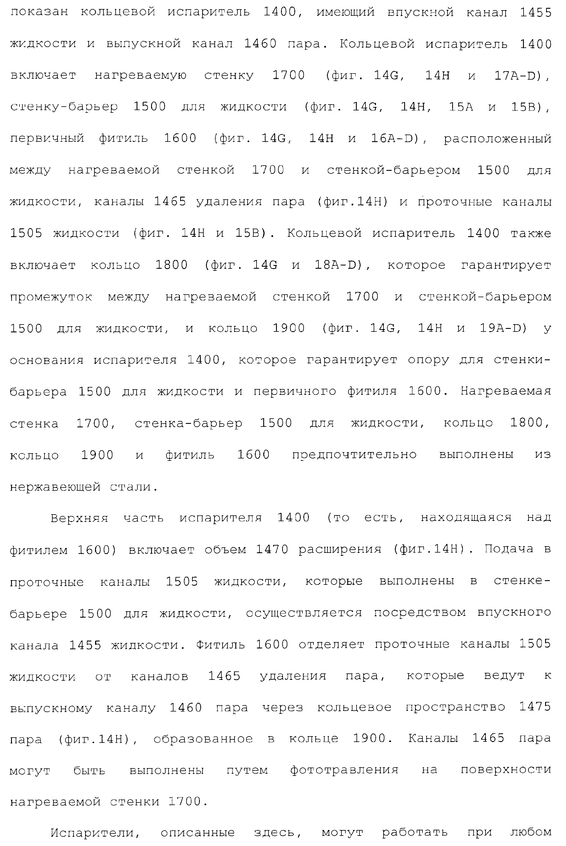
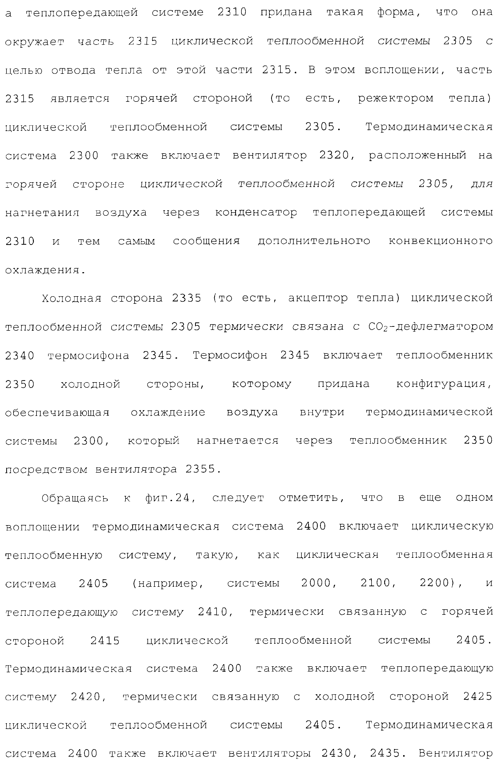
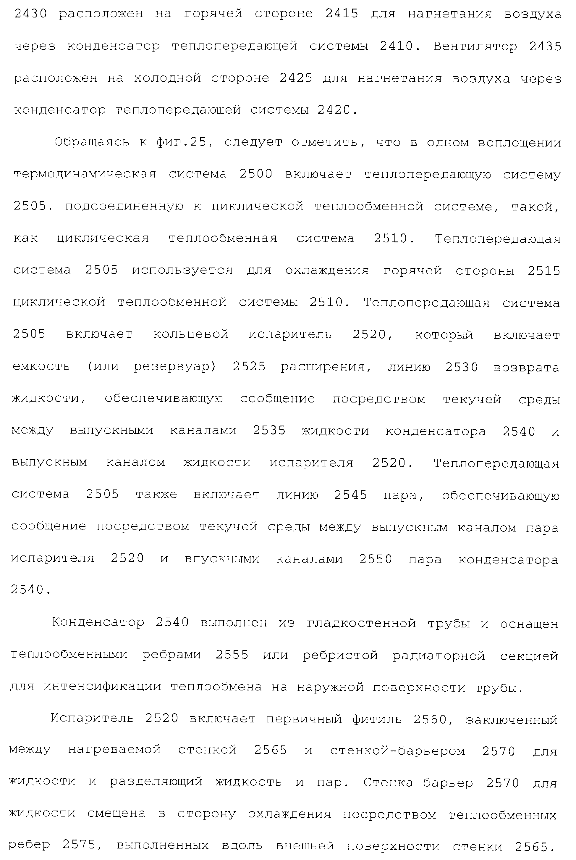
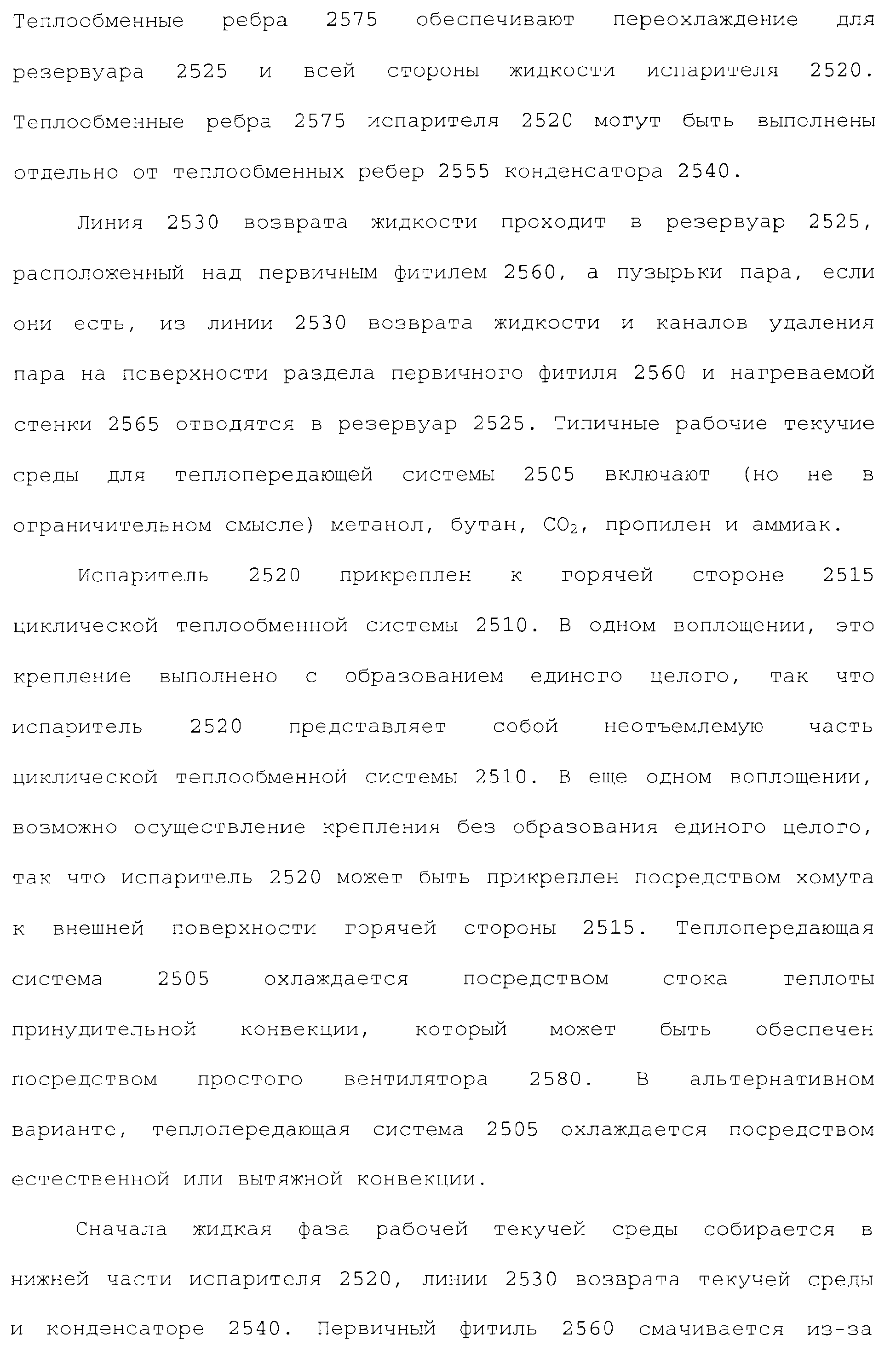
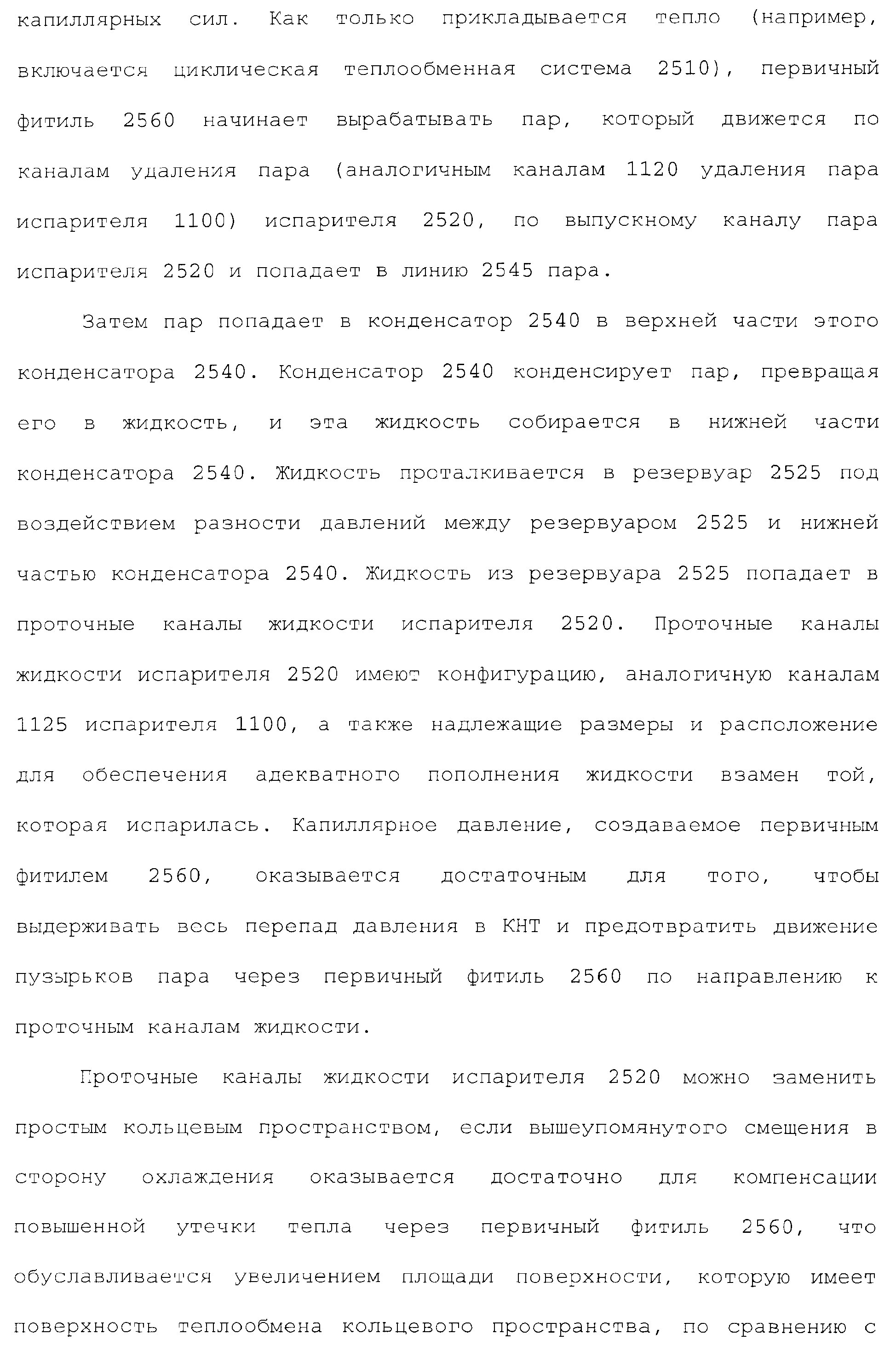
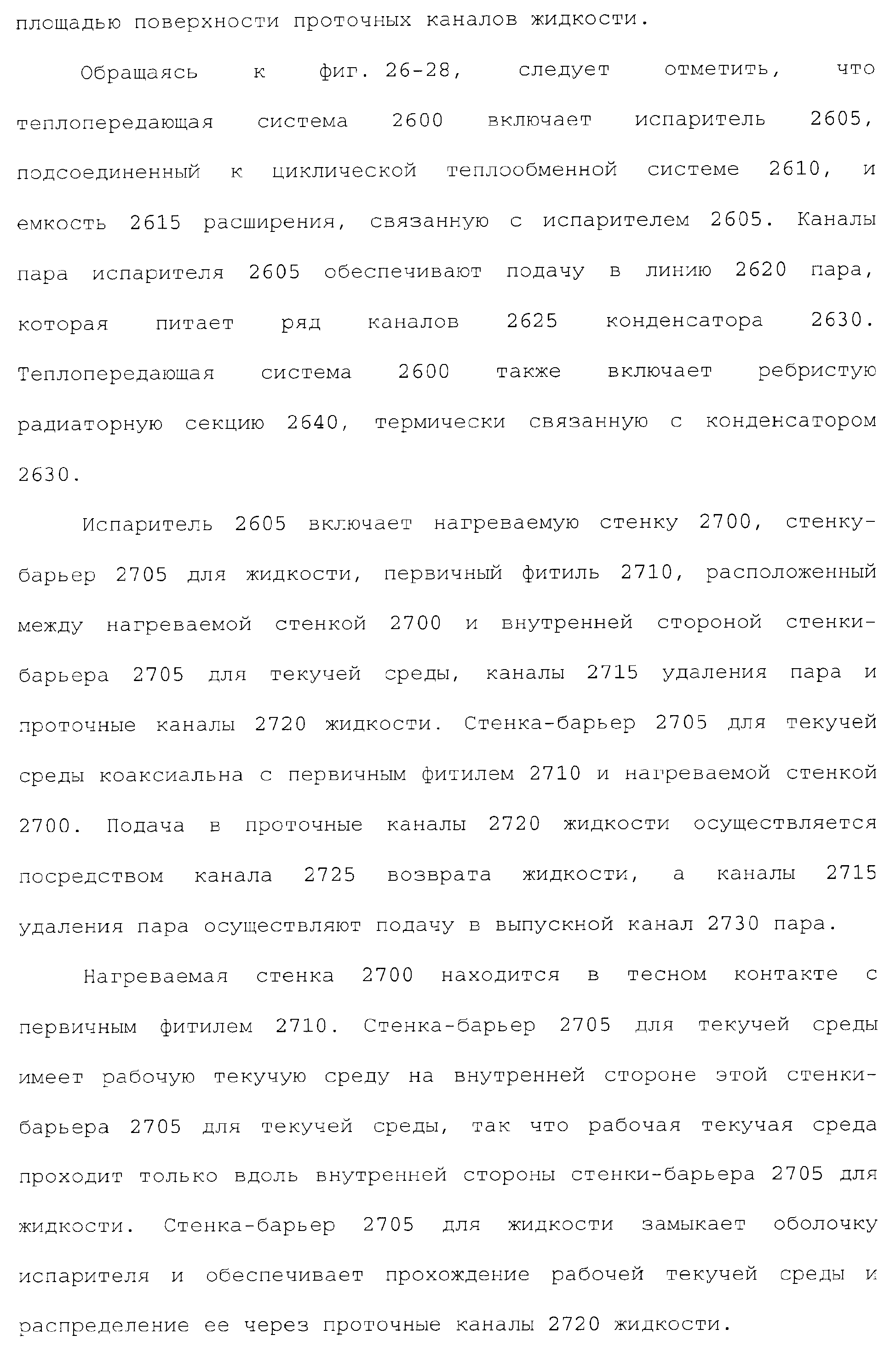
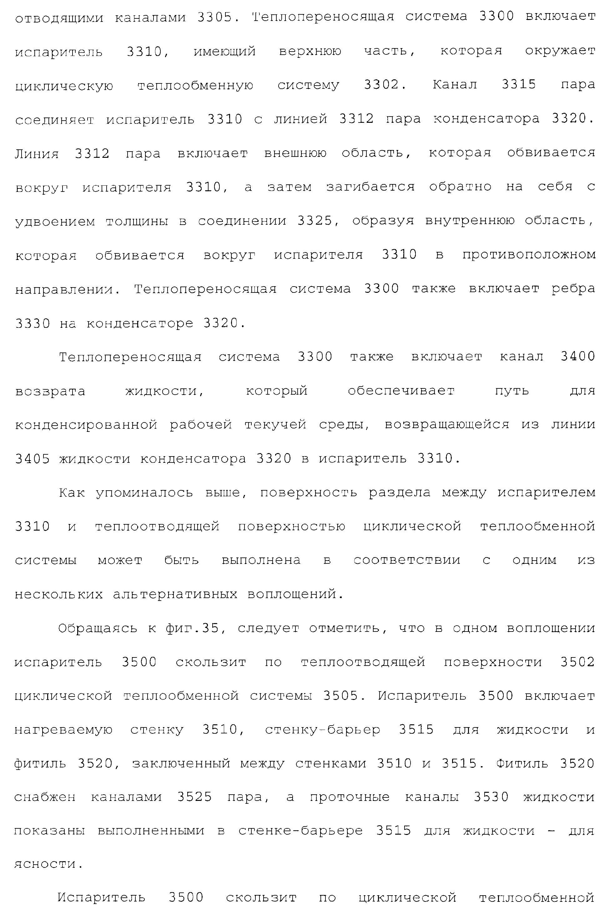
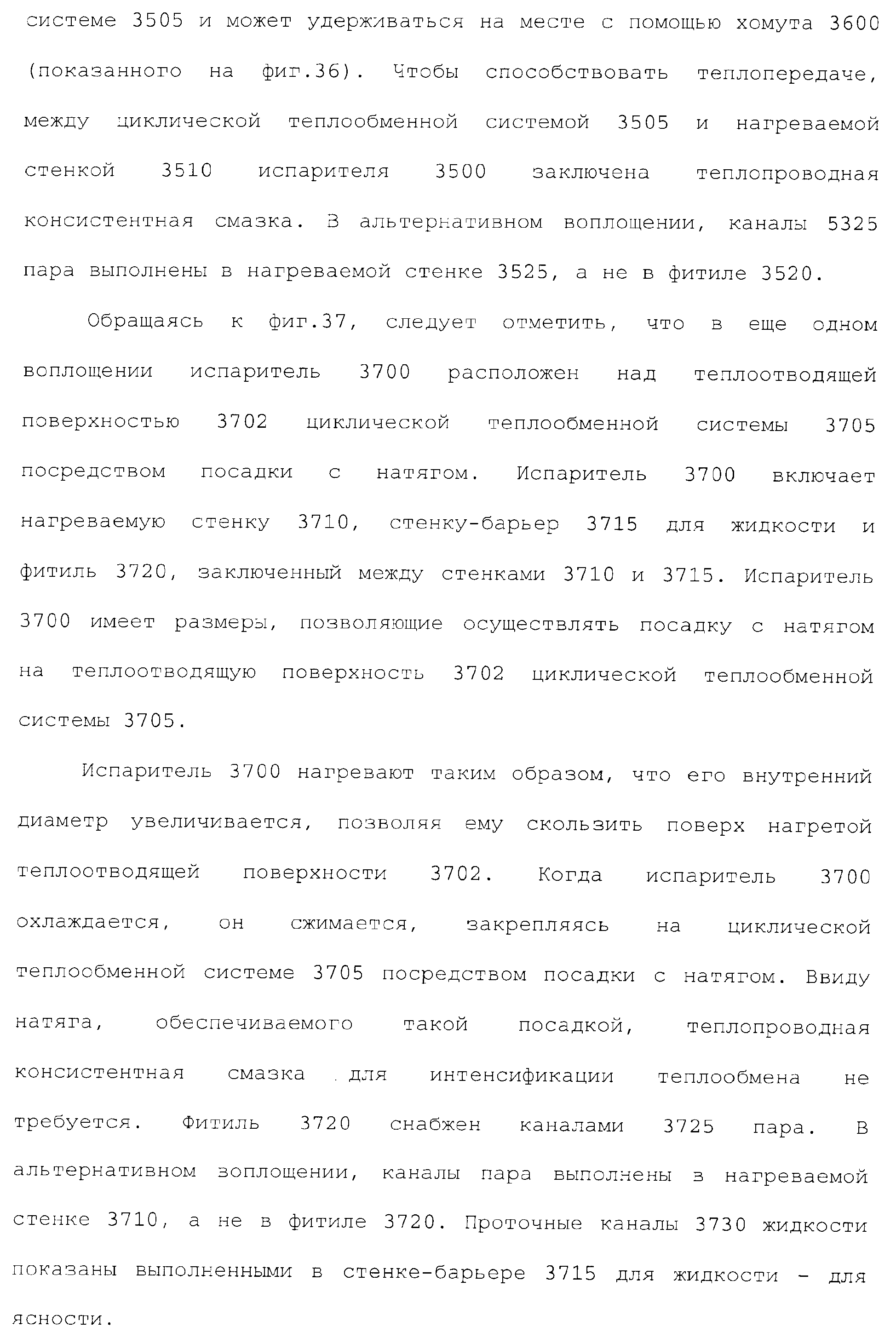
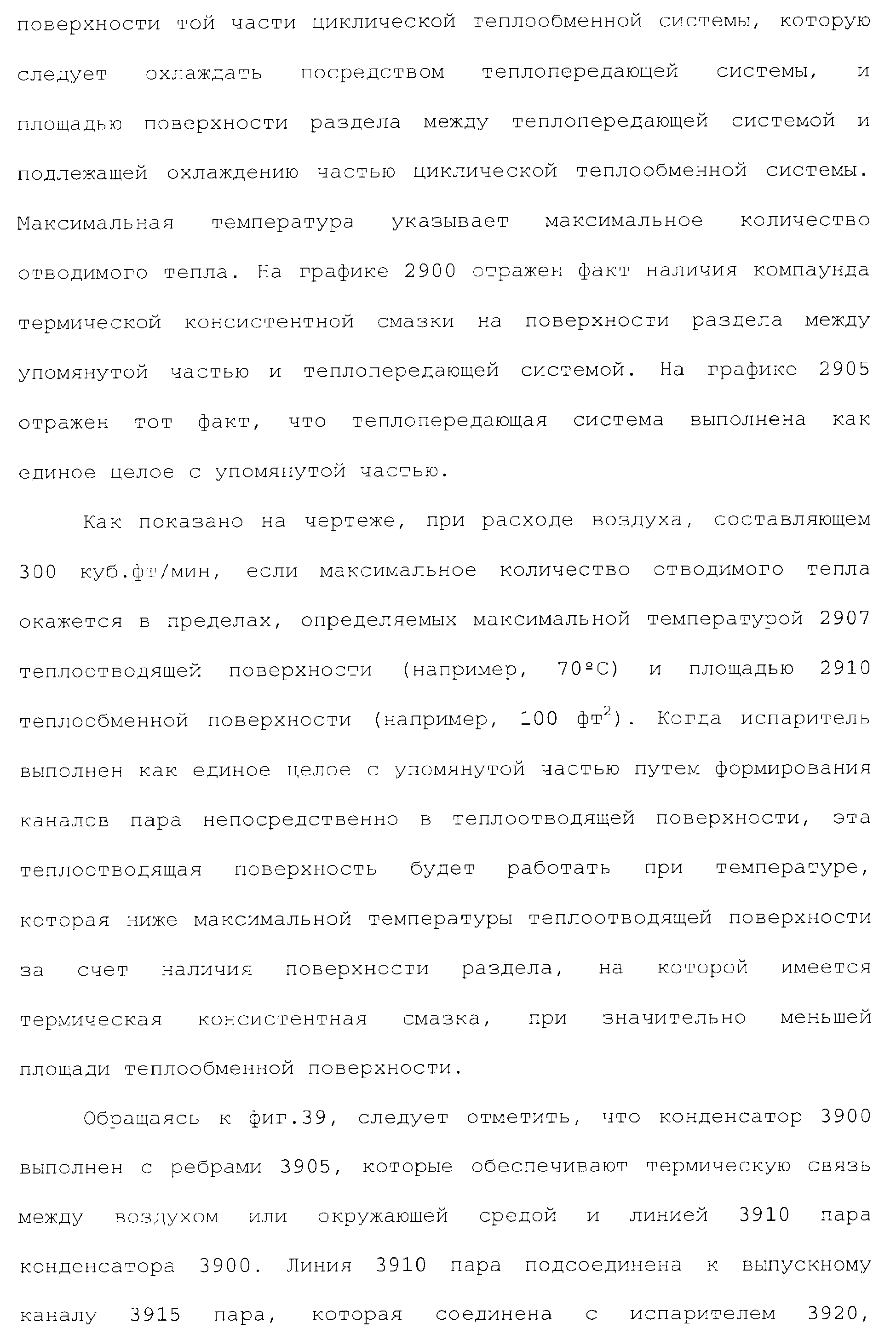
1. Теплопередающая система для циклической теплообменной системы, которая выполнена с возможностью работы с использованием термодинамического цикла и заполнена хладагентом, содержащая испаритель, окружающий часть циклической теплообменной системы и имеющий стенку, выполненную с возможностью термического соединения с частью циклической теплообменной системы для регулирования температуры указанной части, первичный фитиль, соединенный по текучей среде со стенкой, и канал удаления пара, который находится на поверхности раздела между первичным фитилем и стенкой, и конденсатор, соединенный по текучей среде с испарителем для образования замкнутого контура, который вмещает рабочую текучую среду для теплопередающей системы.1. A heat transfer system for a cyclic heat transfer system that is configured to operate using a thermodynamic cycle and is filled with refrigerant, comprising an evaporator surrounding a portion of the cyclic heat transfer system and having a wall configured to thermally connect to a portion of the cyclic heat transfer system to control the temperature of said part, a primary wick fluidly coupled to the wall and a vapor removal channel that is at the interface between a primary wick and a wall, and a condenser fluidly coupled to an evaporator to form a closed loop that holds the working fluid for the heat transfer system.
2. Теплопередающая система по п.1, в которой конденсатор содержит впускной канал пара и выпускной канал жидкости, дополнительно содержащая линию пара, обеспечивающую сообщение по текучей среде между выпускным каналом пара и впускным каналом пара, и линию возврата жидкости, обеспечивающую сообщение по текучей среде между выпускным каналом жидкости и впускным каналом жидкости.2. The heat transfer system according to claim 1, wherein the condenser comprises a steam inlet and a liquid outlet, further comprising a steam line providing fluid communication between the steam outlet and the steam inlet, and a liquid return line providing fluid communication between the fluid outlet and the fluid inlet.
3. Теплопередающая система по п.2, в которой канал удаления пара проходит к выпускному каналу пара, а испаритель содержит: стенку-барьер для жидкости, причем на внутренней стороне этой стенки-барьера для жидкости содержится рабочая текучая среда, так что рабочая текучая среда проходит только по внутренней стороне стенки-барьера для жидкости, при этом первичный фитиль расположен между стенкой и внутренней стороной стенки-барьера для жидкости, и проточный канал жидкости, находящийся между стенкой-барьером для жидкости и первичным фитилем, причем проточный канал жидкости принимает жидкость из впускного канала жидкости.3. The heat transfer system according to claim 2, in which the vapor removal channel extends to the steam exhaust channel, and the evaporator comprises: a liquid barrier wall, wherein a working fluid is contained on the inside of this liquid barrier wall, so that the working fluid passes only along the inner side of the liquid barrier wall, with the primary wick located between the wall and the inner side of the liquid barrier wall, and the fluid flow channel located between the liquid barrier wall and the primary wick, p When in use, the fluid flow channel receives a fluid from the inlet fluid.
4. Теплопередающая система по п.1, в которой рабочая текучая среда перемещается через теплопередающую систему пассивно.4. The heat transfer system according to claim 1, in which the working fluid moves passively through the heat transfer system.
5. Теплопередающая система по п.4, в которой рабочая текучая среда перемещается через теплопередающую систему без использования внешнего перекачивания.5. The heat transfer system according to claim 4, in which the working fluid is moved through the heat transfer system without the use of external pumping.
6. Теплопередающая система по п.2, в которой рабочая текучая среда изменяется между жидкостью и паром, когда рабочая текучая среда проходит через одну или более таких частей, как испаритель, конденсатор, линия пара и линия возврата жидкости.6. The heat transfer system of claim 2, wherein the working fluid changes between liquid and steam when the working fluid passes through one or more parts such as an evaporator, a condenser, a steam line, and a liquid return line.
7. Теплопередающая система по п.1, в которой испаритель имеет кольцевую форму и окружает часть циклической теплообменной системы.7. The heat transfer system according to claim 1, in which the evaporator has an annular shape and surrounds part of a cyclic heat exchange system.
8. Теплопередающая система по п.1, в которой рабочая текучая среда перемещается через теплопередающую систему с использованием фитиля.8. The heat transfer system according to claim 1, in which the working fluid is moved through the heat transfer system using a wick.
9. Теплопередающая система по п.1, дополнительно содержащая ребра, термически соединенные с конденсатором, для отвода тепла в окружающую среду.9. The heat transfer system according to claim 1, further comprising fins thermally coupled to the condenser to remove heat into the environment.
10. Теплопередающая система по п.1, в которой указанная часть представляет собой теплоотводящую поверхность циклической теплообменной системы, а испаритель имеет внутренний диаметр, который увеличивается для скольжения поверх указанной части.10. The heat transfer system of claim 1, wherein said part is a heat sink surface of a cyclic heat exchange system, and the evaporator has an inner diameter that increases to slide over said part.
11. Теплопередающая система по п.1, в которой циклическая теплообменная система включает в себя одну циклическую теплообменную систему.11. The heat transfer system according to claim 1, in which the cyclic heat transfer system includes one cyclic heat transfer system.
12. Теплопередающая система по п.1, в которой стенка испарителя термически соединена с внешней поверхностью части циклической теплообменной системы.12. The heat transfer system according to claim 1, in which the wall of the evaporator is thermally connected to the outer surface of the part of the cyclic heat transfer system.
13. Теплопередающая система по п.1, в которой конденсатор окружает испаритель, при этом теплоотводящая поверхность циклической теплообменной системы окружена испарителем.13. The heat transfer system according to claim 1, in which the condenser surrounds the evaporator, while the heat sink surface of the cyclic heat exchange system is surrounded by the evaporator.
14. Теплопередающая система по п.1, в которой стенка контактирует с частью циклической теплообменной системы.14. The heat transfer system according to claim 1, in which the wall is in contact with part of the cyclic heat transfer system.
15. Теплопередающая система по п.14, в которой стенка контактирует с указанной частью посредством посадки с натягом.15. The heat transfer system according to 14, in which the wall is in contact with the specified part by means of a tight fit.
16. Теплопередающая система по п.1, дополнительно содержащая теплопроводящий материал, расположенный между стенкой и указанной частью, при этом стенка термически соединена с указанной частью через теплопроводящий материал.16. The heat transfer system according to claim 1, additionally containing a heat-conducting material located between the wall and the specified part, while the wall is thermally connected to the specified part through the heat-conducting material.
17. Теплопередающая система по п.1, в которой испаритель выполнен за одно целое с циклической теплообменной системой, а канал удаления пара образован в стороне циклической теплообменной системы.17. The heat transfer system according to claim 1, in which the evaporator is integral with the cyclic heat exchange system, and the vapor removal channel is formed on the side of the cyclic heat transfer system.
18. Теплопередающая система по п.1, в которой канал удаления пара образован в первичном фитиле.18. The heat transfer system according to claim 1, in which a vapor removal channel is formed in the primary wick.
19. Термодинамическая система, содержащая циклическую теплообменную систему, которая заполнена хладагентом и теплопередающую систему, термически соединенную с циклической теплообменной системой для охлаждения части циклической теплообменной системы, при этом теплопередающая система содержит испаритель, окружающий часть циклической теплообменной системы и имеющий стенку, выполненную с возможностью термического соединения с частью циклической теплообменной системы, первичный фитиль, соединенный по текучей среде со стенкой, и канал удаления пара, который находится на поверхности раздела между первичным фитилем и стенкой и конденсатор, соединенный по текучей среде с испарителем для образования замкнутого контура, который вмещает рабочую текучую среду для теплопередающей системы.19. A thermodynamic system comprising a cyclic heat exchange system that is filled with a refrigerant and a heat transfer system thermally connected to a cyclic heat exchange system for cooling a portion of the cyclic heat exchange system, the heat transfer system comprising an evaporator surrounding a portion of the cyclic heat exchange system and having a wall configured to thermally connections to a part of the cyclic heat exchange system, a primary wick fluidly connected to the wall, and a channel Dalen steam which is at the interface between the primary wick and the wall and a condenser coupled in fluid communication with the evaporator to form a closed loop that houses a working fluid for a heat transfer system.
20. Термодинамическая система по п.19, в которой испаритель выполнен за одно целое с циклической теплообменной системой.20. The thermodynamic system according to claim 19, in which the evaporator is made in one piece with a cyclic heat exchange system.
21. Термодинамическая система по п.19, в которой испаритель прикреплен к циклической теплообменной системе.21. The thermodynamic system of claim 19, wherein the evaporator is attached to a cyclic heat exchange system.
22. Термодинамическая система по п.19, в которой циклическая теплообменная система содержит двигатель Стирлинга.22. The thermodynamic system of claim 19, wherein the cyclic heat exchange system comprises a Stirling engine.
23. Термодинамическая система по п.19, в которой циклическая теплообменная система содержит холодильную систему.23. The thermodynamic system of claim 19, wherein the cyclic heat exchange system comprises a refrigeration system.
24. Термодинамическая система по п.19, в которой теплопередающая система подсоединена к горячей стороне циклической теплообменной системы.24. The thermodynamic system of claim 19, wherein the heat transfer system is connected to the hot side of the cyclic heat transfer system.
25. Термодинамическая система по п.19, в которой теплопередающая система подсоединена к холодной стороне циклической теплообменной системы.25. The thermodynamic system of claim 19, wherein the heat transfer system is connected to the cold side of the cyclic heat transfer system.
26. Термодинамическая система по п.19, в которой теплопередающая система окружает часть циклической теплообменной системы.26. The thermodynamic system of claim 19, wherein the heat transfer system surrounds a portion of the cyclic heat transfer system.
27. Термодинамическая система по п.19, в которой испаритель имеет внутренний диаметр, который увеличивается для скольжения поверх теплоотводящей поверхности циклической теплообменной системы.27. The thermodynamic system of claim 19, wherein the evaporator has an inner diameter that increases to slide over the heat sink surface of the cyclic heat exchange system.
28. Термодинамическая система по п.19, в которой циклическая теплообменная система содержит одну циклическую теплообменную систему.28. The thermodynamic system of claim 19, wherein the cyclic heat exchange system comprises one cyclic heat exchange system.
29. Термодинамическая система по п.19, в которой стенка испарителя термически соединена с внешней поверхностью части цилиндрической теплообменной системы.29. The thermodynamic system of claim 19, wherein the evaporator wall is thermally coupled to the outer surface of a portion of the cylindrical heat exchange system.
30. Термодинамическая система по п.19, в которой конденсатор окружает испаритель, при этом теплоотводящая поверхность циклической теплообменной системы окружена испарителем.30. The thermodynamic system of claim 19, wherein the condenser surrounds the evaporator, wherein the heat sink surface of the cyclic heat exchange system is surrounded by the evaporator.
31. Способ регулирования температуры части циклической теплообменной системы, которая заполнена хладагентом, включающий термическое соединение стенки испарителя с циклической теплообменной системой для регулирования температуры части циклической теплообменной системы посредством окружения стенкой части циклической теплообменной системы; соединение по текучей среде первичного фитиля со стенкой; образование канала удаления пара на поверхности раздела между первичным фитилем и стенкой, и соединение по текучей среде конденсатора с испарителем для образования замкнутого контура, который вмещает рабочую текучую среду для теплопередающей системы.
31. A method of controlling the temperature of a portion of a cyclic heat transfer system that is filled with refrigerant, comprising: thermally connecting an evaporator wall to a cyclic heat transfer system to control the temperature of a portion of a cyclic heat transfer system by surrounding a wall of a portion of the cyclic heat transfer system; fluid connection of the primary wick to the wall; the formation of a vapor removal channel at the interface between the primary wick and the wall, and fluid connection of the condenser with the evaporator to form a closed loop that accommodates the working fluid for the heat transfer system.


 The text of the description is given in facsimile form.