RU2368039C2 - Method for balanced charging lithium-ion or lithium-polymer battery - Google Patents
Method for balanced charging lithium-ion or lithium-polymer battery Download PDFInfo
- Publication number
- RU2368039C2 RU2368039C2 RU2006121543/09A RU2006121543A RU2368039C2 RU 2368039 C2 RU2368039 C2 RU 2368039C2 RU 2006121543/09 A RU2006121543/09 A RU 2006121543/09A RU 2006121543 A RU2006121543 A RU 2006121543A RU 2368039 C2 RU2368039 C2 RU 2368039C2
- Authority
- RU
- Russia
- Prior art keywords
- battery
- charging
- voltage
- batteries
- current
- Prior art date
Links
Images
Classifications
-
- H—ELECTRICITY
- H01—ELECTRIC ELEMENTS
- H01M—PROCESSES OR MEANS, e.g. BATTERIES, FOR THE DIRECT CONVERSION OF CHEMICAL ENERGY INTO ELECTRICAL ENERGY
- H01M10/00—Secondary cells; Manufacture thereof
- H01M10/42—Methods or arrangements for servicing or maintenance of secondary cells or secondary half-cells
- H01M10/425—Structural combination with electronic components, e.g. electronic circuits integrated to the outside of the casing
-
- H—ELECTRICITY
- H01—ELECTRIC ELEMENTS
- H01M—PROCESSES OR MEANS, e.g. BATTERIES, FOR THE DIRECT CONVERSION OF CHEMICAL ENERGY INTO ELECTRICAL ENERGY
- H01M10/00—Secondary cells; Manufacture thereof
- H01M10/42—Methods or arrangements for servicing or maintenance of secondary cells or secondary half-cells
- H01M10/44—Methods for charging or discharging
- H01M10/441—Methods for charging or discharging for several batteries or cells simultaneously or sequentially
-
- H—ELECTRICITY
- H01—ELECTRIC ELEMENTS
- H01M—PROCESSES OR MEANS, e.g. BATTERIES, FOR THE DIRECT CONVERSION OF CHEMICAL ENERGY INTO ELECTRICAL ENERGY
- H01M10/00—Secondary cells; Manufacture thereof
- H01M10/42—Methods or arrangements for servicing or maintenance of secondary cells or secondary half-cells
- H01M10/48—Accumulators combined with arrangements for measuring, testing or indicating the condition of cells, e.g. the level or density of the electrolyte
- H01M10/482—Accumulators combined with arrangements for measuring, testing or indicating the condition of cells, e.g. the level or density of the electrolyte for several batteries or cells simultaneously or sequentially
-
- H—ELECTRICITY
- H02—GENERATION; CONVERSION OR DISTRIBUTION OF ELECTRIC POWER
- H02J—CIRCUIT ARRANGEMENTS OR SYSTEMS FOR SUPPLYING OR DISTRIBUTING ELECTRIC POWER; SYSTEMS FOR STORING ELECTRIC ENERGY
- H02J7/00—Circuit arrangements for charging or depolarising batteries or for supplying loads from batteries
- H02J7/0013—Circuit arrangements for charging or depolarising batteries or for supplying loads from batteries acting upon several batteries simultaneously or sequentially
- H02J7/0014—Circuits for equalisation of charge between batteries
- H02J7/0016—Circuits for equalisation of charge between batteries using shunting, discharge or bypass circuits
-
- H—ELECTRICITY
- H02—GENERATION; CONVERSION OR DISTRIBUTION OF ELECTRIC POWER
- H02J—CIRCUIT ARRANGEMENTS OR SYSTEMS FOR SUPPLYING OR DISTRIBUTING ELECTRIC POWER; SYSTEMS FOR STORING ELECTRIC ENERGY
- H02J7/00—Circuit arrangements for charging or depolarising batteries or for supplying loads from batteries
- H02J7/0047—Circuit arrangements for charging or depolarising batteries or for supplying loads from batteries with monitoring or indicating devices or circuits
- H02J7/0048—Detection of remaining charge capacity or state of charge [SOC]
-
- H—ELECTRICITY
- H02—GENERATION; CONVERSION OR DISTRIBUTION OF ELECTRIC POWER
- H02J—CIRCUIT ARRANGEMENTS OR SYSTEMS FOR SUPPLYING OR DISTRIBUTING ELECTRIC POWER; SYSTEMS FOR STORING ELECTRIC ENERGY
- H02J7/00—Circuit arrangements for charging or depolarising batteries or for supplying loads from batteries
- H02J7/0013—Circuit arrangements for charging or depolarising batteries or for supplying loads from batteries acting upon several batteries simultaneously or sequentially
- H02J7/0014—Circuits for equalisation of charge between batteries
- H02J7/0019—Circuits for equalisation of charge between batteries using switched or multiplexed charge circuits
-
- Y—GENERAL TAGGING OF NEW TECHNOLOGICAL DEVELOPMENTS; GENERAL TAGGING OF CROSS-SECTIONAL TECHNOLOGIES SPANNING OVER SEVERAL SECTIONS OF THE IPC; TECHNICAL SUBJECTS COVERED BY FORMER USPC CROSS-REFERENCE ART COLLECTIONS [XRACs] AND DIGESTS
- Y02—TECHNOLOGIES OR APPLICATIONS FOR MITIGATION OR ADAPTATION AGAINST CLIMATE CHANGE
- Y02E—REDUCTION OF GREENHOUSE GAS [GHG] EMISSIONS, RELATED TO ENERGY GENERATION, TRANSMISSION OR DISTRIBUTION
- Y02E60/00—Enabling technologies; Technologies with a potential or indirect contribution to GHG emissions mitigation
- Y02E60/10—Energy storage using batteries
Abstract
Description
Настоящее изобретение относится к зарядке или подзарядке аккумуляторных батарей, и его объектом является способ сбалансированной зарядки аккумуляторов литий-ионной или литий-полимерной батареи.The present invention relates to charging or recharging rechargeable batteries, and its object is a method for balanced charging of rechargeable batteries of a lithium-ion or lithium-polymer battery.
Оптимизация электрической зарядки батарей, содержащих несколько аккумуляторов, представляет собой сложную проблему, в частности, когда число последовательно соединенных элементов или аккумуляторов является достаточно большим.Optimizing the electrical charging of batteries containing multiple batteries is a complex problem, in particular when the number of cells or batteries connected in series is sufficiently large.
В случае литий-ионных или литий-полимерных батарей к этим проблемам оптимизации зарядки различных элементов или аккумуляторов добавляется опасность необратимого разрушения указанных элементов или аккумуляторов в случае перегрузки, в частности при перегреве или при чрезмерном напряжении.In the case of lithium-ion or lithium-polymer batteries, the danger of irreversible destruction of the indicated cells or batteries in case of overload, in particular during overheating or under excessive voltage, is added to these problems of optimizing charging of various cells or batteries.
С одной стороны, известно, что в батареях, содержащих последовательно соединенные литий-ионные или литий-полимерные элементы, параметры емкости каждого элемента или аккумулятора после зарядки не являются идентичными, и эти различия возрастают от цикла к циклу зарядки и разрядки вплоть до конца срока службы данной батареи.On the one hand, it is known that in batteries containing lithium-ion or lithium-polymer cells connected in series, the capacitance parameters of each cell or battery after charging are not identical, and these differences increase from cycle to cycle of charging and discharging until the end of their service life this battery.
С другой стороны, известно, что литий-ионные или литий-полимерные батареи не допускают как перегрузки в процессе зарядки, так и неполной зарядки в связи с использованием (разрядка). Установленное значение максимального напряжения, приведенное в качестве неограничительного примера, при перегрузке для каждого из соединенных последовательно литий-ионных или литий-полимерных элементов составляет 4,20 В, а установленное напряжение для прекращения разрядки и предотвращения, таким образом, ухудшения рабочих характеристик батареи равно 2,70 В.On the other hand, it is known that lithium-ion or lithium-polymer batteries do not allow both overloading during charging and incomplete charging due to use (discharge). The set value of the maximum voltage, given as a non-limiting example, during overload for each of the series-connected lithium-ion or lithium-polymer cells is 4.20 V, and the set voltage to stop discharging and prevent, therefore, deterioration of battery performance is 2 , 70 V.
Известно также, что для каждого литий-ионного или литий-полимерного элемента напряжение на контактах элемента или аккумулятора отражает величину емкости, накопленную в данном элементе или аккумуляторе. Это указание напряжения не дает представления о точном значении емкости в ампер-часах или ватт-часах, а только отражает величину емкости рассматриваемого элемента в момент измерения этого напряжения в виде процента от номинальной емкости.It is also known that for each lithium-ion or lithium-polymer cell, the voltage across the contacts of the cell or battery reflects the amount of capacitance accumulated in the cell or battery. This indication of the voltage does not give an idea of the exact value of the capacitance in ampere-hours or watt-hours, but only reflects the value of the capacitance of the element in question at the time of measuring this voltage as a percentage of the nominal capacity.
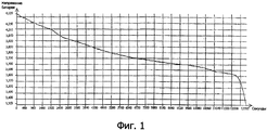
На фиг.1 прилагаемых чертежей показана кривая, отражающая изменение напряжения на контактах литий-ионного элемента в зависимости от его емкости (речь идет о кривой разрядки для постоянного тока, при этом время пропорционально проценту от номинальной емкости, накопленной в рассматриваемом литий-ионном элементе, при этом: 0 секунд ⇒ 95% (4,129 В), 6 150 секунд ⇒ 50% (3,760 В) и 12 300 секунд ⇒ 0% (3,600 В). Можно заметить, что на большей части этой кривой емкость уменьшается почти линейно от времени, а затем резко падает. Для контроля за операциями зарядки и разрядки литий-ионного элемента или аккумулятора используют эту почти линейную часть, что позволяет утверждать, что напряжение является отражением емкости.Figure 1 of the accompanying drawings shows a curve reflecting the change in voltage at the contacts of a lithium-ion cell depending on its capacitance (we are talking about a discharge curve for direct current, while the time is proportional to the percentage of the nominal capacitance accumulated in the lithium-ion cell under consideration, in this case: 0 seconds ⇒ 95% (4,129 V), 6 150 seconds ⇒ 50% (3,760 V) and 12,300 seconds ⇒ 0% (3,600 V) You can see that in most of this curve the capacitance decreases almost linearly with time and then drops sharply to control charging and discharging ki of the lithium ion battery cell or use this near-linear portion, that suggests that the strain is a reflection capacity.
С учетом положений трех предыдущих пунктов можно удостовериться, что в батарее, состоящей из трех-четырех последовательно соединенных литий-ионных или литий-полимерных элементов, зарядка прекращается, когда напряжение наиболее заряженного элемента достигает 4,20 В и, наоборот, разрядка прекращается, когда напряжение элемента с наименьшей емкостью достигает 2,70 В: таким образом, элемент с наименьшей емкостью определяет общую емкость батареи. Это позволяет понять, что, когда батарея содержит много последовательно соединенных элементов, риск неполного использования емкости батареи становится реальным, так как элемент с наименьшей емкостью ограничительно определяет общую емкость батареи. Кроме того, это явление проявляется еще больше по мере увеличения числа циклов зарядки/разрядки.Taking into account the provisions of the three previous paragraphs, you can make sure that in a battery consisting of three to four series-connected lithium-ion or lithium-polymer cells, charging stops when the voltage of the most charged cell reaches 4.20 V and, conversely, discharging stops when the voltage of the cell with the lowest capacity reaches 2.70 V: thus, the cell with the lowest capacity determines the total capacity of the battery. This makes it clear that when a battery contains many cells connected in series, the risk of underutilization of the battery capacity becomes real, since the element with the smallest capacity restricts the overall battery capacity. In addition, this phenomenon manifests itself even more as the number of charge / discharge cycles increases.
Такое явление разбалансировки зарядки в основном вызвано различиями емкости и внутреннего сопротивления между элементами батареи, причем эти различия зависят также от качества изготовления литий-ионных или литий-полимерных элементов.This phenomenon of unbalanced charging is mainly caused by differences in capacitance and internal resistance between the battery cells, and these differences also depend on the manufacturing quality of lithium-ion or lithium-polymer cells.
Для оптимизации величины емкости батареи во времени, что имеет большое значение для рентабельности эксплуатации, необходимо решить указанную выше проблему путем коррекции балансировки всех элементов или всех аккумуляторов батареи. Эта балансировка должна обеспечивать 100%-ную зарядку всех элементов, независимо от их емкости.To optimize the value of the battery capacity over time, which is of great importance for the profitability of operation, it is necessary to solve the above problem by correcting the balance of all elements or all battery batteries. This balancing should provide 100% charge of all elements, regardless of their capacity.
В существующей практике такую балансировку производят в конце зарядки, отводя зарядный ток от элемента, заряженного на 100%, то есть когда он достигает напряжения в 4,20 В. Таким образом, зарядка элементов прекращается по мере того, как они достигают 4,20 В, и, таким образом, получают 100% зарядку всех элементов в конце операции зарядки.In existing practice, such balancing is performed at the end of charging, diverting the charging current from the cell 100% charged, that is, when it reaches a voltage of 4.20 V. Thus, the charging of the cells stops as they reach 4.20 V , and thus, 100% charge of all cells at the end of the charging operation is obtained.
Однако этот известный способ балансировки в конце зарядки имеет существенные недостатки.However, this known balancing method at the end of charging has significant drawbacks.
Так, эти системы балансировки требуют наличия мощных сопротивлений для обеспечения отвода соответствующих токов, тем более что система балансировки вступает в действие, когда зарядные токи остаются еще достаточно большими, что происходит, когда элементы батареи очень разбалансированы.So, these balancing systems require powerful resistances to ensure the removal of the corresponding currents, especially since the balancing system comes into effect when the charging currents are still large enough, which happens when the battery cells are very unbalanced.
Кроме того, такое сильное рассеяние мощности приводит к соответствующему повышению температуры, что создает проблемы в случае компактных батарей, содержащих токоотводящие резисторы.In addition, such strong power dissipation leads to a corresponding increase in temperature, which creates problems in the case of compact batteries containing collector resistors.
Кроме того, может случиться, что, несмотря на подачу больших зарядных токов ближе к концу операции зарядки, батарея оказывается не сбалансированной после выполнения условий зарядки.In addition, it may happen that, despite the supply of large charging currents towards the end of the charging operation, the battery is not balanced after the charging conditions are met.
Кроме того, в батареях большой мощности периоды зарядки батареи, в частности периоды полной зарядки, являются продолжительными и даже очень продолжительными. Поэтому часто случается, что реального времени зарядки между двумя фазами разрядки не хватает для завершения операции зарядки, и зарядка прерывается, тогда как разбалансировка между элементами или аккумуляторами еще не устранена (в случае использования системы балансировки в конце зарядки, известной из предшествующего уровня техники). Повторение этого явления приводит к быстрому ухудшению рабочих характеристик рассматриваемой батареи.In addition, in high power batteries, periods of charging the battery, in particular periods of full charge, are long and even very long. Therefore, it often happens that the real time of charging between the two phases of the discharge is not enough to complete the charging operation, and the charging is interrupted, while the imbalance between the cells or batteries has not yet been eliminated (in the case of using the balancing system at the end of the charge, known from the prior art). A repetition of this phenomenon leads to a rapid deterioration in the performance of the battery in question.
Настоящее изобретение призвано предложить решение оптимальной зарядки, характеризующееся вышеуказанными преимуществами и позволяющее устранить вышеупомянутые недостатки известных технических решений.The present invention is intended to provide an optimal charging solution, characterized by the above advantages and to eliminate the above-mentioned disadvantages of the known technical solutions.
В этой связи объектом настоящего изобретения является способ сбалансированной зарядки n аккумуляторов, где n≥2, входящих в состав литий-ионной или литий-полимерной батареи и соединенных последовательно, при этом каждый аккумулятор состоит из одного или нескольких элементов, соединенных параллельно, отличающийся тем, что с начала операции зарядки батареи и в течение всей этой операции осуществляют постоянный контроль за уровнями зарядки различных аккумуляторов и в зависимости от предварительной оценки указанных уровней зарядки либо равномерно подают ток на все аккумуляторы, либо выполняют балансировку уровней зарядки аккумуляторов путем дифференцированной подачи на них тока в зависимости от их текущих уровней зарядки.In this regard, the object of the present invention is a method for the balanced charging of n batteries, where n≥2 included in a lithium-ion or lithium-polymer battery and connected in series, each battery consisting of one or more cells connected in parallel, characterized in that that from the beginning of the operation of charging the battery and throughout this operation, they constantly monitor the charge levels of various batteries and depending on a preliminary assessment of the indicated charge levels or evenly supply current to all batteries, or balance the levels of battery charging by differentially supplying current to them depending on their current charge levels.
Указанные выше этапы можно выполнять двумя разными способами, основанными на двух разных технологических возможностях.The above steps can be performed in two different ways, based on two different technological capabilities.
Так, при применении решения, главным образом основанного на аналоговой технологии, контроль за уровнями зарядки выполняют непрерывно и дифференцированную подачу питания осуществляют, как только разность уровней зарядки между максимально заряженным(и) аккумулятором(ами) и минимально заряженным(и) аккумулятором(ами) превышает заранее определенное пороговое значение, и до тех пор, пока имеется превышение порогового значения.So, when applying a solution, mainly based on analog technology, charge levels are monitored continuously and differential supply of power is performed as soon as the difference in charge levels between the maximum charged battery (s) and the minimum charged battery (s) exceeds a predetermined threshold value, and as long as there is an excess of the threshold value.
В варианте, соответствующем предпочтительному решению, в котором используют цифровую обработку сигналов и управление процессом при помощи цифрового блока обработки данных, контроль за уровнями зарядки осуществляют путем повторяющихся измерений и дифференцированной подачи питания в течение заранее определенного времени, в случае проверки установленных условий разбалансировки уровней зарядки.In an embodiment corresponding to the preferred solution, which uses digital signal processing and process control using a digital data processing unit, charge levels are monitored by repeated measurements and differentiated power supply for a predetermined time, if the established conditions for the unbalance of the charge levels are checked.
Это второе решение позволяет одновременно упростить материальное и программное обеспечение, необходимое для осуществления способа.This second solution allows you to simultaneously simplify the material and software necessary for the implementation of the method.
В рамках этого второго решения способ предпочтительно состоит в поочередном выполнении для каждого аккумулятора батареи в течение промежутка времени, входящего в общее время зарядки батареи, последовательно повторяющихся этапов оценки уровней зарядки данного аккумулятора, после которой, в зависимости от уровня его зарядки и от уровней зарядки всех остальных аккумуляторов батареи, осуществляют подачу одинакового или дифференцированного питания, причем цикл повторяют в течение всей операции зарядки.In the framework of this second solution, the method preferably consists in alternately performing for each battery of the battery for a period of time included in the total time of charging the battery, successively repeating steps of estimating the charge levels of the battery, after which, depending on its charge level and on the charge levels of all the remaining battery packs, supply the same or differentiated power, the cycle being repeated during the entire charging operation.
Согласно предпочтительному варианту осуществления настоящего изобретения указанный способ содержит, по меньшей мере, выполнение следующих операций под управлением цифрового блока обработки данных, причем с самого начала зарядки:According to a preferred embodiment of the present invention, said method comprises at least performing the following operations under the control of a digital data processing unit, from the very beginning of charging:
- оценка, предпочтительно через равномерные интервалы, количества энергии, накопленной в каждом аккумуляторе, путем измерения параметра, отражающего это количество;- assessment, preferably at regular intervals, of the amount of energy stored in each battery by measuring a parameter that reflects this amount;
- сравнительный анализ определенных оценкой разных количеств энергии или разных значений измеряемого параметра;- a comparative analysis of different quantities of energy or different values of the measured parameter determined by the assessment;
- определение аккумулятора, наиболее отстающего по зарядке, и, в случае необходимости, наиболее опережающего(их) по зарядке аккумулятора(ов);- determination of the battery most lagging behind in charging, and, if necessary, the most advanced (for them) in charging the battery (s);
- подача питания на разные последовательно соединенные аккумуляторы, равномерно или с ограничением зарядного тока для аккумуляторов, отличных от наиболее отстающего по зарядке аккумулятора, или для наиболее опережающего(их) по зарядке аккумулятора(ов) путем отвода всего или части указанного тока на уровне этого(их) последнего(их) аккумулятора(ов);- supplying power to different series-connected batteries, uniformly or with a limitation of the charging current for batteries other than the most lagging in charging the battery, or for the most advanced (for them) in charging the battery (s) by removing all or part of the specified current at the level of this ( their) last (s) battery (s);
- последовательное повторение вышеуказанных операций до достижения состояния завершения зарядки батареи или до обнаружения дефекта, нарушения в работе или превышения допустимого порогового значения.- sequential repetition of the above operations until the state of completion of charging the battery or until a defect is detected, a malfunction or the threshold is exceeded.
Произведенные заявителем испытания и работы показали, что этот способ последовательной балансировки, осуществляемый поэтапно в течение всего времени зарядки, позволяет достичь одинакового процентного уровня зарядки всех элементов или аккумуляторов батареи в данный момент зарядки и, более того, 100%-ной зарядки всех элементов батареи в конце зарядки, причем независимо от их собственной емкости.Tests and works performed by the applicant showed that this method of sequential balancing, carried out in stages throughout the entire charging time, allows to achieve the same percentage charge level of all battery cells or batteries at the moment of charging and, moreover, 100% charge of all battery cells in end of charge, and regardless of their own capacity.
Настоящее изобретение будет более очевидно из нижеследующего описания предпочтительного варианта осуществления, приведенного в качестве не ограничительного примера, со ссылками на прилагаемые схематические чертежи, на которых:The present invention will be more apparent from the following description of a preferred embodiment, given by way of non-limiting example, with reference to the accompanying schematic drawings, in which:
фиг.2 - блок-схема устройства, предназначенного для осуществления способа в соответствии с настоящим изобретением;figure 2 is a block diagram of a device for implementing the method in accordance with the present invention;
фиг.3 - более подробная схема устройства, показанного на фиг.2, согласно варианту осуществления настоящего изобретения;figure 3 is a more detailed diagram of the device shown in figure 2, according to a variant implementation of the present invention;
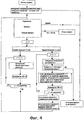
фиг.4 - структурная схема различных этапов способа согласно варианту осуществления изобретения (на этой схеме под термином «элемент» следует понимать элемент или аккумулятор с параллельно соединенными элементами);4 is a structural diagram of the various steps of a method according to an embodiment of the invention (in this diagram, the term "cell" means a cell or battery with cells connected in parallel);
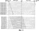
фиг.5 - временные диаграммы, приведенные в качестве не ограничительного примера и показывающие для батареи из двенадцати аккумуляторов операции, осуществляемые в течение цикла зарядки с балансировкой при помощи способа в соответствии с настоящим изобретением.5 is a timing chart, given by way of non-limiting example and showing operations for a battery of twelve batteries during a charging cycle with balancing by the method in accordance with the present invention.
Объектом настоящего изобретения является способ сбалансированной зарядки n аккумуляторов 1, где n≥2, входящих в состав литий-ионной или литий-полимерной батареи 2 и соединенных последовательно, при этом каждый аккумулятор 1 состоит из одного или нескольких элементов, установленных параллельно.The object of the present invention is a method for the balanced charging of
Согласно предпочтительному варианту осуществления настоящего изобретения указанный способ содержит, по меньшей мере, выполнение следующих операций под управлением цифрового блока обработки данных, причем с самого начала зарядки:According to a preferred embodiment of the present invention, said method comprises at least performing the following operations under the control of a digital data processing unit, from the very beginning of charging:
- оценка, предпочтительно через равномерные интервалы, количества энергии, накопленной в каждом аккумуляторе 1, путем измерения параметра, характеризующего это количество;- evaluation, preferably at regular intervals, of the amount of energy stored in each
- сравнительный анализ определенных путем оценки разных количеств энергии или разных значений измеряемого параметра;- a comparative analysis determined by evaluating different amounts of energy or different values of the measured parameter;
- определение аккумулятора 1, наиболее отстающего по зарядке, и, в случае необходимости, наиболее опережающего(их) по зарядке аккумулятора(ов) 1;- determination of
- подача питания на разные последовательно соединенные аккумуляторы 1, равномерно или с ограничением зарядного тока для аккумуляторов 1, отличных от наиболее отстающего по зарядке аккумулятора 1, а для наиболее опережающего(их) по зарядке аккумулятора(ов) 1 путем отвода всего или части указанного тока на уровне этого(их) последнего(их) аккумулятора(ов);- power supply to different series-connected
- последовательное повторение вышеуказанных операций до достижения состояния конца зарядки батареи 2 или до обнаружения дефекта, нарушения в работе или превышения допустимого порогового значения.- sequential repetition of the above operations until the state of the end of charging of the battery 2 is reached or until a defect is detected, a malfunction, or a threshold is exceeded.
Предпочтительно параметром, измеряемым для каждого аккумулятора 1 и используемым для оценки количества накопленной в нем энергии, является напряжение на контактах рассматриваемого аккумулятора 1.Preferably, the parameter measured for each
Как уже было указано выше, ограничения зарядного тока могут касаться всех аккумуляторов, опережающих по зарядке наименее заряженный аккумулятор, причем, в случае необходимости, с разной степенью ограничения питания.As mentioned above, the charging current restrictions can apply to all batteries that are ahead of charging the least charged battery, and, if necessary, with varying degrees of power limitation.
Вместе с тем, чтобы еще больше расширить активные фазы балансировки согласно изобретению, предпочтительно только аккумулятор или аккумуляторы, уровень зарядки которого(ых) наиболее опережает уровень зарядки наименее заряженного аккумулятора (в течение заданной доли времени n), подвергается(ются) ограничению зарядки (в течение следующей доли времени n+1). Таким образом, для аккумуляторов, уровень зарядки которых только слегка превышает уровень зарядки наименее заряженного аккумулятора, зарядка будет продолжаться в нормальном режиме.However, in order to further expand the active phases of balancing according to the invention, preferably only the battery or batteries, the charge level of which (s) is ahead of the charge level of the least charged battery (for a given fraction of time n), is subject to charge limitation (in during the next fraction of the time n + 1). Thus, for batteries whose charge level is only slightly higher than the charge level of the least charged battery, charging will continue in normal mode.
Различие между аккумуляторами, подвергнутыми и не подвергнутыми временному ограничению зарядки (в течение доли времени от общего времени зарядки), может, например, вытекать из состояния (с точки зрения значений) уровней зарядки этих аккумуляторов по отношению к заданному пороговому значению [значение зарядки наименее заряженного аккумулятора + дельта (Δ)].The difference between batteries subjected to and not subjected to a temporary charge limitation (within a fraction of the time of the total charging time) may, for example, result from the state (in terms of values) of the charge levels of these batteries with respect to a predetermined threshold value [charge value of the least charged battery + delta (Δ)].
Кроме того, принимая стратегию ограничения зарядного тока наиболее заряженных аккумуляторов в течение всей зарядки батареи, не дожидаясь конца указанной зарядки, изобретение позволяет избежать любой возможности перегрева батареи 2 из-за поздней балансировки и обеспечить сбалансированное напряжение на уровне аккумуляторов 1 в конце зарядки.In addition, adopting the strategy of limiting the charging current of the most charged batteries during the entire charging of the battery, without waiting for the end of the indicated charging, the invention avoids any possibility of overheating of the battery 2 due to late balancing and provides a balanced voltage at the level of the
Кроме того, осуществляя балансировку с самого начала зарядки и продолжая ее в течение всей операции зарядки, батарею поддерживают практически в сбалансированном состоянии в течение всей операции зарядки, то есть даже в случае прекращения зарядки до ее нормального завершения зарядки.In addition, by balancing from the very beginning of charging and continuing it throughout the entire charging operation, the battery is maintained in a practically balanced state throughout the entire charging operation, that is, even if charging is stopped before it is normally charged.
Согласно предпочтительному отличительному признаку настоящего изобретения отвод тока на уровне наиболее опережающего(их) по зарядке аккумулятора(ов) 1 осуществляют при помощи параллельных цепей 4, каждая из которых путем параллельного монтажа соединена с одним из указанных аккумуляторов 1 (одна цепь 4 на каждый аккумулятор 1), при этом каждая из указанных цепей 4 содержит коммутационный элемент 5 и, в случае необходимости, по меньшей мере, один, возможно регулируемый, элемент 6 рассеяния электрической энергии, такой, например, как электрический резистор (фиг.2 и 3).According to a preferred distinguishing feature of the present invention, the current is drawn off at the level of the most advanced charge (s) for charging the battery (s) 1 by means of
Коммутационный элемент 5 можно выбирать, например, из группы, в которую входят электромеханические или электронные реле, биполярные или полевые транзисторы, или аналогичные устройства.The switching element 5 can be selected, for example, from the group that includes electromechanical or electronic relays, bipolar or field effect transistors, or similar devices.
Кроме того, поскольку отвод энергии, связанный с балансировкой зарядки различных аккумуляторов 1, распределяют по всей продолжительности зарядки, то можно оптимизировать как коммутационный элемент 5, так и соответствующий рассеивающий элемент 6.In addition, since the energy drain associated with balancing the charging of
Согласно предпочтительному варианту осуществления настоящего изобретения для зарядки с последовательной балансировкой выполняют, в частности, следующие операции, возобновляемые в течение всего процесса зарядки батареи 2:According to a preferred embodiment of the present invention, for charging with sequential balancing, in particular, the following operations are performed, which are renewed during the entire charging process of the battery 2:
а) за каждым отдельным аккумулятором 1 батареи 2 ведут наблюдение, измеряя напряжение на контактах, не подключая при этом токоотводящие или балансировочные резисторы 6;a) each
б) определяют аккумулятор 1, наиболее отстающий по зарядке;b) determine the
в) определяют аккумуляторы 1, которые, по отношению к наименее заряженному или наиболее отстающему по зарядке аккумулятору 1, имеют превышение зарядки сверх заранее определенного порогового значения отклонения емкости, например, соответствующего разности напряжения (dVs) в 10 мВ;C) determine the
г) каждый обнаруженный аккумулятор 1 с превышением зарядки сверх порогового значения индивидуально подключают к соответствующему балансировочному резистору 6 таким образом, чтобы понизить зарядный ток для каждого из рассматриваемых аккумуляторов 1, например, на 10% в течение заранее определенного промежутка времени, например в течение двух секунд;d) each detected
д) по истечении указанного заранее определенного промежутка времени балансировочные резисторы 6 отключают;d) after the specified predetermined period of time, the
е) по истечении периода стабилизации напряжения аккумуляторов 1 повторяют этапы а)-д).e) after the stabilization period of the voltage of the
Обычно зарядку батареи останавливают, когда общий зарядный ток всех аккумуляторов этой батареи опускается ниже заранее определенного порогового значения, например 50 мА.Typically, battery charging is stopped when the total charging current of all the batteries of this battery drops below a predetermined threshold value, such as 50 mA.
В примере практического применения настоящего изобретения значения мощности различных параллельных цепей 4 выбирают близкими к значениям, получаемым при помощи следующей формулыIn an example of practical application of the present invention, the power values of various
![]()
![]()
гдеWhere
Psd max - максимальная оптимизированная рассеиваемая мощность, выраженная в Вт;Psd max - maximum optimized power dissipation expressed in watts;
Vmax акк. - максимальное напряжение, измеренное в ходе зарядки на контактах аккумулятора, выраженное в В;Vmax acc. - the maximum voltage measured during charging at the battery terminals, expressed in V;
% - соотношение, выраженное в процентах, соответствующее максимальному отклонению между двумя аккумуляторами, зарядку которых необходимо сбалансировать;% - ratio, expressed as a percentage, corresponding to the maximum deviation between two batteries, the charging of which must be balanced;
АН - номинальная емкость батареи, выраженная в А·ч (ампер-час);AN - nominal battery capacity, expressed in Ah · (ampere-hour);
Тс - время зарядки батареи, выраженное в часах.Tc - battery charging time, expressed in hours.
Кроме того, чтобы достичь точного и постепенного регулирования зарядки каждого аккумулятора 1, напряжение на контактах каждого аккумулятора 1 точно измеряют при помощи соответствующего комплекса 7 измерительных модулей 7', выходные сигналы которых, предпочтительно после оцифровки, передаются на цифровой блок 3 обработки данных, при этом последний на следующем цикле управляет коммутационными механизмами 5 различных параллельных цепей 4 в зависимости от сравнительного изменения указанных выходных сигналов, направляемых модулями 7'.In addition, in order to achieve accurate and gradual regulation of the charging of each
Согласно наиболее предпочтительному варианту осуществления настоящего изобретения, показанному на фиг.4 и 5, операции повторяют в течение всего процесса зарядки в виде замкнутого цикла, состоящего из двух рабочих полуциклов, выполняемых последовательно при каждом завершении цикла, при этом первый полуцикл содержит последовательное выполнение следующих операций: последовательное считывание значений напряжения на различных аккумуляторах 1 и подключение со смещением во времени балансировочного резистора 6 для каждого аккумулятора 1, разность напряжений (dV) которого с наиболее отстающим по зарядке аккумулятором 1 превышает пороговое значение (dVs), а второй полуцикл содержит следующие операции:According to the most preferred embodiment of the present invention shown in FIGS. 4 and 5, the operations are repeated during the entire charging process in the form of a closed cycle consisting of two working half-cycles executed sequentially at each completion of the cycle, while the first half-cycle contains sequential execution of the following operations : sequential reading of voltage values on
последовательное отключение балансировочных резисторов 6 от различных аккумуляторов 1 и выжидание стабилизации напряжений на различных аккумуляторах 1 перед следующим считыванием во время первого полуцикла следующего цикла, при этом оба полуцикла предпочтительно имеют примерно одинаковую продолжительность, например, приблизительно 2 с.sequentially disconnecting the balancing
Благодаря циклическому возобновлению операций двух полуциклов (при продолжительности цикла, например, 4 с) в течение всего процесса зарядки батареи 2, то есть до завершения зарядки или появления предупреждающей информации на индикаторе, все аккумуляторы 1 (и элемент или элементы каждого из этих аккумуляторов) в любой момент характеризуются незначительным разбросом емкости (за счет постоянных соединений нагрузки между аккумуляторами) и самым оптимальным образом максимально восстанавливают свои характеристики.Due to the cyclical resumption of the operations of two half-cycles (for a cycle duration, for example, 4 s) during the entire charging process of battery 2, that is, until charging is complete or warning information appears on the indicator, all batteries 1 (and the element or elements of each of these batteries) in any moment is characterized by a slight variation in capacitance (due to constant load connections between the batteries) and in the most optimal way restore their characteristics as much as possible.
Кроме того, способ в соответствии с настоящим изобретением позволяет допускать в начале зарядки большие перепады уровней зарядки между аккумуляторами 1, при этом «нивелирование» или балансировка происходит на протяжении всего процесса зарядки батареи 2.In addition, the method in accordance with the present invention allows to allow at the beginning of charging large differences in charge levels between the
Согласно первому варианту можно предусмотреть, чтобы пороговое значение разности напряжений dVs представляло собой первое заранее определенное фиксированное значение V1, например 10 мВ, если разность напряжений dV между напряжением на аккумуляторе 1, имеющем самое высокое напряжение, и напряжением на аккумуляторе 1, имеющем самое низкое напряжение, меньше второго заранее определенного фиксированного значения V2, превышающего первое заранее определенное пороговое значение V1, например 100 мВ.According to the first embodiment, it can be provided that the threshold voltage difference dVs is a first predetermined fixed value V1, for example 10 mV, if the voltage difference dV between the voltage on the
Кроме того, можно также предусмотреть, чтобы, если разность напряжений dV между напряжением на аккумуляторе 1, имеющем самое высокое напряжение, и напряжением на аккумуляторе 1, имеющем самое низкое напряжение, превышает второе заранее определенное фиксированное значение V2, например 100 мВ, пороговое значение разности напряжений dVs представляет собой третье заранее определенное фиксированное значение V3, меньшее указанного второго значения V2, например 30 мВ.In addition, it can also be provided that if the voltage difference dV between the voltage on the
Предпочтительно третье заранее определенное фиксированное значение V3 превышает указанное первое заранее определенное фиксированное значение V1.Preferably, the third predetermined fixed value V3 exceeds the specified first predetermined fixed value V1.
Согласно второму варианту альтернативно можно предусмотреть, чтобы пороговое значение разности напряжений dVs соответствовало заданной доле разности напряжений dV, измеренной во время предыдущего цикла, между напряжением на аккумуляторе 1 с самым высоким напряжением и напряжением на аккумуляторе 1 с самым низким напряжением, если во время текущего цикла указанная разность напряжений dV превышает четвертое заранее определенное фиксированное значение V4, например 10 мВ.According to the second variant, it can alternatively be provided that the threshold value of the voltage difference dVs corresponds to a given fraction of the voltage difference dV measured during the previous cycle between the voltage on the
Предпочтительно в каждом из двух указанных вариантов и, как уже было указано ранее, измерения напряжений на различных аккумуляторах 1 осуществляют только по истечении заданного промежутка времени, например 2 с, после отвода токов таким образом, чтобы дождаться стабилизации напряжений на контактах указанных аккумуляторов 1.It is preferable in each of the two indicated options and, as already mentioned, voltage measurements on
Чтобы уберечь аккумуляторы 1 батареи 2 от возможных скачков напряжения, программа управления зарядкой, структурная схема которой представлена в качестве примера на фиг.4, может содержать выполнение определенного числа проверок перед началом зарядки, в ходе зарядки и после завершения зарядки.In order to protect the
Так, перед началом выполнения операций способа зарядки можно выполнять измерение напряжения холостого хода Vo зарядного устройства 8, подключенного к батарее 2 для ее зарядки, и прекращение процесса зарядки с возможным включением тревожного сигнала и/или индикацией визуального сигнала, если напряжение холостого хода Vo превышает [n × максимально допустимое напряжение Vmax для каждого аккумулятора 1].So, before starting the operation of the charging method, it is possible to measure the open circuit voltage Vo of the charger 8 connected to the battery 2 to charge it, and terminate the charging process with the possible inclusion of an alarm and / or visual signal if the open circuit voltage Vo exceeds [ n × the maximum allowable voltage Vmax for each battery 1].
Точно так же указанный способ перед выполнением следующего замкнутого цикла или следующего цикла может включать проверку для того, чтобы, если, по меньшей мере, один из аккумуляторов 1 батареи 2 имеет на своих контактах напряжение, превышающее максимально допустимое напряжение Vmax (например и не ограничительно, 4,23 В), прерывать процесс зарядки с возможным включением тревожного сигнала и/или индикацией визуального сигнала.Similarly, the method may include checking before performing the next closed cycle or the next cycle so that if at least one of the
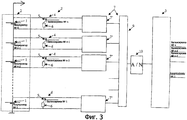
Объектом настоящего изобретения является также устройство для осуществления описанного выше способа, основные компоненты которого схематично показаны на фиг.2 и 3.The object of the present invention is also a device for implementing the above method, the main components of which are schematically shown in figure 2 and 3.
Это устройство в основном содержит комплекс 7 модулей 7' измерения напряжения, каждый из которых связан с одним из последовательно соединенных аккумуляторов 1, образующих батарею 2, и измеряет напряжение на контактах этих аккумуляторов, множество токоотводящих цепей 4, каждая из которых соединена параллельно с контактами соответствующего аккумулятора 1 и каждая из которых может быть разомкнута или замкнута выборочно, и цифровой блок 3 обработки данных и управления способом, при этом на указанный блок 3 поступают сигналы измерения от комплекса 7 модулей 7' измерения напряжения, и он управляет состоянием (замкнутое/разомкнутое) каждой токоотводящей цепи 4.This device basically contains a complex of 7 voltage measurement modules 7 ', each of which is connected to one of the series-connected
Модули 7' могут представлять собой, например, дифференциальные схемы измерения напряжения с операционным усилителем, характеризующиеся точностью измерения, по меньшей мере, 50 мВ.Modules 7 'can be, for example, differential voltage measurement circuits with an operational amplifier, characterized by a measurement accuracy of at least 50 mV.
Предпочтительно каждая токоотводящая цепь 4 содержит коммутационный элемент 5, который является выключателем, и положение которого управляется цифровым блоком 3 обработки данных, и, в случае необходимости, токоотводящая цепь 4 содержит, по меньшей мере, один элемент 6 рассеяния электрической энергии, такой, как например резистор или резисторы.Preferably, each
Как показано на фиг.3 и согласно предпочтительному варианту осуществления настоящего изобретения, комплекс 7 модулей 7' измерения напряжения содержит n аналоговых модулей 7' измерения, каждый из которых непосредственно связан с аккумулятором 1 батареи 2, мультиплексор 9, входы которого соединены с выходами указанных модулей 7', и аналого-цифровой преобразователь 10, соединенный на входе с выходом мультиплексора 9 и на выходе с цифровым блоком 3 обработки данных и управления.As shown in FIG. 3 and according to a preferred embodiment of the present invention, the
В предпочтительном, но не ограничительном варианте применения устройство, показанное на фиг.2 и 3, предпочтительно может входить в комплект автономного электросилового инструмента.In a preferred, but not restrictive embodiment, the device shown in FIGS. 2 and 3 can preferably be included in a stand-alone power tool.
В этой связи следует отметить, что токоотводящие цепи 4, индивидуально связанные с аккумуляторами 1 батареи 2, могут также использоваться для возможной корректировки зарядки указанных аккумуляторов 1 до уровня, совместимого с длительным хранением указанной батареи 2 без эксплуатации.In this regard, it should be noted that the
Само собой разумеется, что настоящее изобретение не ограничивается описанными и показанными на прилагаемых чертежах вариантами осуществления. В него можно вносить изменения, в частности, с точки зрения компоновки различными элементами или их замены техническими эквивалентами, не выходя при этом за рамки объема правовой охраны изобретения.It goes without saying that the present invention is not limited to the embodiments described and shown in the accompanying drawings. It can be amended, in particular, in terms of layout with various elements or their replacement with technical equivalents, without going beyond the scope of legal protection of the invention.
Claims (20)
оценку, предпочтительно, через равные интервалы времени количества энергии, накопленной в каждом аккумуляторе (1), путем измерения параметра, характеризующего это количество;
сравнительный анализ определенных путем оценки разных количеств энергии или разных значений параметра, измеряемого на каждом аккумуляторе (1);
определение аккумулятора (1), наиболее отстающего по зарядке, и в случае необходимости наиболее опережающего(их) по зарядке аккумулятора(ов) (1);
запитку разных последовательно соединенных аккумуляторов (1) равномерно или с ограничением зарядного тока для аккумуляторов (1), отличных от наиболее отстающего по зарядке аккумулятора, и для наиболее опережающего(их) по зарядке аккумулятора(ов) (1), путем отвода всего или части указанного тока для последнего(их) аккумулятора(ов);
последовательное повторение вышеуказанных операций до окончания зарядки батареи (2) или до обнаружения дефекта, нарушения в работе или превышения допустимого порогового значения.2. The method according to claim 1, characterized in that from the beginning of charging, at least the following operations are performed under the control of a digital data processing unit (3):
estimating, preferably at regular intervals, the amount of energy stored in each battery (1) by measuring a parameter characterizing this amount;
comparative analysis of those determined by evaluating different amounts of energy or different values of a parameter measured on each battery (1);
determination of the battery (1), the most lagging behind in charging, and, if necessary, the most advanced (them) in charging the battery (s) (1);
powering different series-connected batteries (1) uniformly or with a limitation of the charging current for batteries (1) different from the most lagging in charging the battery, and for the most advanced (for them) in charging the battery (s) (1), by removing all or part the indicated current for the last battery (s);
successive repetition of the above operations until the battery is charged (2) or until a defect, a malfunction, or a threshold is exceeded.
а) все аккумуляторы (1) батареи (2) поочередно контролируют путем измерения напряжения на контактах, не подключая при этом токоотводящие или балансировочные резисторы (6);
б) определяют аккумулятор (1), наиболее отстающий по зарядке;
в) определяют аккумуляторы (1), которые по отношению к наименее заряженному или наиболее отстающему по зарядке аккумулятору (1) имеют превышение зарядки сверх заранее определенного порогового значения отклонения емкости, например, соответствующее разности напряжений (dVs) в 10 мВ;
г) каждый обнаруженный аккумулятор (1) с превышением зарядки сверх порогового значения индивидуально подключают к соответствующему балансировочному резистору (6) таким образом, чтобы понизить зарядный ток для каждого из аккумуляторов (1), например, на 10% в течение заранее определенного промежутка времени, например, в течение 2 с;
д) по истечении указанного заранее определенного промежутка времени балансировочные резисторы (6) отключают от всех аккумуляторов (1);
е) по истечении периода стабилизации напряжения аккумуляторов (1) повторяют этапы а)-д).6. The method according to claim 5, characterized in that for charging with sequential balancing, in particular, the following operations are carried out, renewed during the entire process of charging the battery (2):
a) all accumulators (1) batteries (2) are alternately monitored by measuring the voltage across the contacts, without connecting current-carrying or balancing resistors (6);
b) determine the battery (1), the most lagging behind in charging;
C) determine the batteries (1), which in relation to the least charged or the most lagging in charging the battery (1) have an excess of charging over a predetermined threshold value of the deviation of the capacitance, for example, corresponding to a voltage difference (dVs) of 10 mV;
d) each detected battery (1) with excess charging above a threshold value is individually connected to the corresponding balancing resistor (6) in such a way as to reduce the charging current for each of the batteries (1), for example, by 10% for a predetermined period of time, for example, within 2 s;
d) after the specified predetermined period of time, the balancing resistors (6) are disconnected from all batteries (1);
f) after the stabilization period of the battery voltage (1), steps a) to e) are repeated.
последовательное считывание значений напряжения на различных аккумуляторах (1) и подключение со смещением во времени балансировочного резистора (6) для каждого аккумулятора (1), разность напряжений (dV) которого с наиболее отстающим по зарядке аккумулятором (1) превышает пороговое значение (dVs), а второй полуцикл содержит следующие операции: последовательное отключение балансировочных резисторов (6) различных аккумуляторов (1) и выжидание стабилизации напряжений на различных аккумуляторах (1) перед следующим считыванием во время первого полуцикла следующего цикла, при этом оба полуцикла предпочтительно имеют примерно одинаковую продолжительность, например, приблизительно 2 с.9. The method according to any one of claims 2 to 6, characterized in that the operations are repeated during the entire charging process in the form of a closed cycle, consisting of two working half-cycles, executed sequentially at each completion of the closed cycle, the first half-cycle containing the sequential execution of the following operations:
sequential reading of voltage values on various batteries (1) and connection with a time offset of a balancing resistor (6) for each battery (1), the voltage difference (dV) of which with the battery most lagging behind in charging (1) exceeds the threshold value (dVs), and the second half-cycle contains the following operations: sequentially disconnecting the balancing resistors (6) of various batteries (1) and waiting for voltage stabilization on various batteries (1) before the next reading during the first half Ikla next cycle, the two half-cycles preferably have approximately the same length, e.g., approximately 2 seconds.
где Psd max - максимальная оптимизированная рассеиваемая мощность, выраженная в Вт;
Vmax акк. - максимальное напряжение, измеренное в ходе зарядки на контактах аккумулятора, выраженное в В;
% - соотношение, выраженное в процентах, соответствующее максимальному отклонению между двумя аккумуляторами, зарядку которых необходимо сбалансировать;
АН - номинальная емкость батареи, выраженная в А·ч (ампер-час);
Тc - время зарядки батареи, выраженное в часах.15. The method according to claim 4 or 5, characterized in that the power values of the various parallel circuits (4) are chosen close to the values obtained by the following formula:
where Psd max is the maximum optimized power dissipation expressed in watts;
Vmax acc. - the maximum voltage measured during charging at the battery terminals, expressed in V;
% - ratio, expressed as a percentage, corresponding to the maximum deviation between two batteries, the charging of which must be balanced;
AN - nominal battery capacity, expressed in Ah · (ampere-hour);
Tc is the battery charging time, expressed in hours.
Applications Claiming Priority (2)
| Application Number | Priority Date | Filing Date | Title |
|---|---|---|---|
| FR0313570 | 2003-11-20 | ||
| FR0313570A FR2862813B1 (en) | 2003-11-20 | 2003-11-20 | METHOD FOR BALANCED LOADING OF LITHIUM-ION OR POLYMER LITHIUM BATTERY |
Publications (2)
| Publication Number | Publication Date |
|---|---|
| RU2006121543A RU2006121543A (en) | 2008-01-10 |
| RU2368039C2 true RU2368039C2 (en) | 2009-09-20 |
Family
ID=34531135
Family Applications (1)
| Application Number | Title | Priority Date | Filing Date |
|---|---|---|---|
| RU2006121543/09A RU2368039C2 (en) | 2003-11-20 | 2004-11-18 | Method for balanced charging lithium-ion or lithium-polymer battery |
Country Status (13)
| Country | Link |
|---|---|
| US (1) | US7719231B2 (en) |
| EP (1) | EP1685622B3 (en) |
| JP (2) | JP2007513594A (en) |
| CN (1) | CN1998110B (en) |
| AT (1) | ATE458287T1 (en) |
| BR (1) | BRPI0416049B1 (en) |
| CA (1) | CA2546891C (en) |
| DE (1) | DE602004025606D1 (en) |
| DK (1) | DK1685622T3 (en) |
| ES (1) | ES2341253T7 (en) |
| FR (1) | FR2862813B1 (en) |
| RU (1) | RU2368039C2 (en) |
| WO (1) | WO2005055358A2 (en) |
Cited By (6)
| Publication number | Priority date | Publication date | Assignee | Title |
|---|---|---|---|---|
| RU2496190C2 (en) * | 2011-12-22 | 2013-10-20 | Открытое акционерное общество "Информационные спутниковые системы" имени академика М.Ф. Решетнева" | Preparation method of lithium-ion storage battery for standard operation as part of artificial earth satellite |
| WO2014093731A1 (en) * | 2012-12-13 | 2014-06-19 | Manford Wade John | Multiple cell battery management |
| RU2526849C1 (en) * | 2010-08-27 | 2014-08-27 | Ниссан Мотор Ко., Лтд. | Accumulator battery control device |
| RU176470U1 (en) * | 2017-01-27 | 2018-01-22 | Федеральное государственное автономное научное учреждение "Центральный научно-исследовательский и опытно-конструкторский институт робототехники и технической кибернетики" (ЦНИИ РТК) | Control and balancing device for lithium-ion battery |
| RU2647128C2 (en) * | 2015-12-04 | 2018-03-14 | Российская Федерация, от имени которой выступает Министерство обороны Российской Федерации | Method of lithium-ion accumulator battery charge |
| RU2702758C1 (en) * | 2019-02-26 | 2019-10-11 | Акционерное общество "Научно-исследовательский институт электромеханики" | Method for charging a set of accumulator batteries in an autonomous power supply system of a spacecraft |
Families Citing this family (236)
| Publication number | Priority date | Publication date | Assignee | Title |
|---|---|---|---|---|
| US7197363B2 (en) | 2002-04-16 | 2007-03-27 | Vivant Medical, Inc. | Microwave antenna having a curved configuration |
| FR2862558B1 (en) | 2003-11-20 | 2006-04-28 | Pellenc Sa | POWER AUTONOMOUS POWER PORTABLE TOOL |
| US7553309B2 (en) | 2004-10-08 | 2009-06-30 | Covidien Ag | Electrosurgical system employing multiple electrodes and method thereof |
| US7282049B2 (en) | 2004-10-08 | 2007-10-16 | Sherwood Services Ag | Electrosurgical system employing multiple electrodes and method thereof |
| US7776035B2 (en) | 2004-10-08 | 2010-08-17 | Covidien Ag | Cool-tip combined electrode introducer |
| US7846158B2 (en) | 2006-05-05 | 2010-12-07 | Covidien Ag | Apparatus and method for electrode thermosurgery |
| KR100906249B1 (en) * | 2006-09-11 | 2009-07-07 | 주식회사 엘지화학 | Control Method of Battery-System for Improving Safety |
| JP5179047B2 (en) * | 2006-11-27 | 2013-04-10 | パナソニック株式会社 | Storage device abnormality detection device, storage device abnormality detection method, and abnormality detection program thereof |
| US9375246B2 (en) | 2007-01-19 | 2016-06-28 | Covidien Lp | System and method of using thermal and electrical conductivity of tissue |
| US8211099B2 (en) | 2007-01-31 | 2012-07-03 | Tyco Healthcare Group Lp | Thermal feedback systems and methods of using the same |
| US9166422B2 (en) | 2007-02-26 | 2015-10-20 | Black & Decker Inc. | Battery based portable power supply |
| JP4388094B2 (en) * | 2007-03-28 | 2009-12-24 | 株式会社東芝 | Battery pack protection device and battery pack device |
| US7998139B2 (en) | 2007-04-25 | 2011-08-16 | Vivant Medical, Inc. | Cooled helical antenna for microwave ablation |
| US7777130B2 (en) | 2007-06-18 | 2010-08-17 | Vivant Medical, Inc. | Microwave cable cooling |
| US8152800B2 (en) | 2007-07-30 | 2012-04-10 | Vivant Medical, Inc. | Electrosurgical systems and printed circuit boards for use therewith |
| US8181995B2 (en) | 2007-09-07 | 2012-05-22 | Tyco Healthcare Group Lp | Cool tip junction |
| JP5250230B2 (en) | 2007-09-28 | 2013-07-31 | 株式会社日立製作所 | Power supply system for vehicle and integrated circuit for battery cell control |
| US9622813B2 (en) | 2007-11-01 | 2017-04-18 | Covidien Lp | Method for volume determination and geometric reconstruction |
| US8280525B2 (en) | 2007-11-16 | 2012-10-02 | Vivant Medical, Inc. | Dynamically matched microwave antenna for tissue ablation |
| US8292880B2 (en) | 2007-11-27 | 2012-10-23 | Vivant Medical, Inc. | Targeted cooling of deployable microwave antenna |
| US7713076B2 (en) | 2007-11-27 | 2010-05-11 | Vivant Medical, Inc. | Floating connector for microwave surgical device |
| US8131339B2 (en) | 2007-11-27 | 2012-03-06 | Vivant Medical, Inc. | System and method for field ablation prediction |
| US9057468B2 (en) | 2007-11-27 | 2015-06-16 | Covidien Lp | Wedge coupling |
| JP5279261B2 (en) | 2007-12-27 | 2013-09-04 | 三洋電機株式会社 | Charge state equalization apparatus and assembled battery system including the same |
| CN101471575B (en) * | 2007-12-28 | 2010-12-01 | 凹凸科技(中国)有限公司 | Equilibrium control circuit for multi-battery set |
| KR101156977B1 (en) | 2007-12-31 | 2012-06-20 | 에스케이이노베이션 주식회사 | Method for Balancing of High Voltage Battery Pack |
| JP5024055B2 (en) * | 2008-01-07 | 2012-09-12 | パナソニック株式会社 | Power storage device |
| WO2009087956A1 (en) * | 2008-01-07 | 2009-07-16 | Panasonic Corporation | Electricity accumulating device |
| JP5024053B2 (en) * | 2008-01-07 | 2012-09-12 | パナソニック株式会社 | Power storage device |
| JP5024054B2 (en) * | 2008-01-07 | 2012-09-12 | パナソニック株式会社 | Power storage device |
| US8945111B2 (en) | 2008-01-23 | 2015-02-03 | Covidien Lp | Choked dielectric loaded tip dipole microwave antenna |
| US7642451B2 (en) | 2008-01-23 | 2010-01-05 | Vivant Medical, Inc. | Thermally tuned coaxial cable for microwave antennas |
| US8435237B2 (en) | 2008-01-29 | 2013-05-07 | Covidien Lp | Polyp encapsulation system and method |
| US8262703B2 (en) | 2008-01-31 | 2012-09-11 | Vivant Medical, Inc. | Medical device including member that deploys in a spiral-like configuration and method |
| US8353902B2 (en) | 2008-01-31 | 2013-01-15 | Vivant Medical, Inc. | Articulating ablation device and method |
| US8221418B2 (en) | 2008-02-07 | 2012-07-17 | Tyco Healthcare Group Lp | Endoscopic instrument for tissue identification |
| US9949794B2 (en) | 2008-03-27 | 2018-04-24 | Covidien Lp | Microwave ablation devices including expandable antennas and methods of use |
| US9198723B2 (en) | 2008-03-31 | 2015-12-01 | Covidien Lp | Re-hydration antenna for ablation |
| US8246614B2 (en) | 2008-04-17 | 2012-08-21 | Vivant Medical, Inc. | High-strength microwave antenna coupling |
| US8059059B2 (en) | 2008-05-29 | 2011-11-15 | Vivant Medical, Inc. | Slidable choke microwave antenna |
| US9271796B2 (en) | 2008-06-09 | 2016-03-01 | Covidien Lp | Ablation needle guide |
| US8192427B2 (en) | 2008-06-09 | 2012-06-05 | Tyco Healthcare Group Lp | Surface ablation process with electrode cooling methods |
| US8343149B2 (en) | 2008-06-26 | 2013-01-01 | Vivant Medical, Inc. | Deployable microwave antenna for treating tissue |
| US8834409B2 (en) | 2008-07-29 | 2014-09-16 | Covidien Lp | Method for ablation volume determination and geometric reconstruction |
| US9173706B2 (en) | 2008-08-25 | 2015-11-03 | Covidien Lp | Dual-band dipole microwave ablation antenna |
| US8211098B2 (en) | 2008-08-25 | 2012-07-03 | Vivant Medical, Inc. | Microwave antenna assembly having a dielectric body portion with radial partitions of dielectric material |
| US8251987B2 (en) | 2008-08-28 | 2012-08-28 | Vivant Medical, Inc. | Microwave antenna |
| US8403924B2 (en) | 2008-09-03 | 2013-03-26 | Vivant Medical, Inc. | Shielding for an isolation apparatus used in a microwave generator |
| US8394086B2 (en) | 2008-09-03 | 2013-03-12 | Vivant Medical, Inc. | Microwave shielding apparatus |
| US9375272B2 (en) | 2008-10-13 | 2016-06-28 | Covidien Lp | Antenna assemblies for medical applications |
| US8512328B2 (en) | 2008-10-13 | 2013-08-20 | Covidien Lp | Antenna assemblies for medical applications |
| US9113624B2 (en) | 2008-10-15 | 2015-08-25 | Covidien Lp | System and method for perfusing biological organs |
| US9113924B2 (en) | 2008-10-17 | 2015-08-25 | Covidien Lp | Choked dielectric loaded tip dipole microwave antenna |
| US8197473B2 (en) | 2009-02-20 | 2012-06-12 | Vivant Medical, Inc. | Leaky-wave antennas for medical applications |
| US8202270B2 (en) | 2009-02-20 | 2012-06-19 | Vivant Medical, Inc. | Leaky-wave antennas for medical applications |
| US8118808B2 (en) | 2009-03-10 | 2012-02-21 | Vivant Medical, Inc. | Cooled dielectrically buffered microwave dipole antenna |
| US9277969B2 (en) | 2009-04-01 | 2016-03-08 | Covidien Lp | Microwave ablation system with user-controlled ablation size and method of use |
| US10045819B2 (en) | 2009-04-14 | 2018-08-14 | Covidien Lp | Frequency identification for microwave ablation probes |
| US8463396B2 (en) | 2009-05-06 | 2013-06-11 | Covidien LLP | Power-stage antenna integrated system with high-strength shaft |
| US8216227B2 (en) | 2009-05-06 | 2012-07-10 | Vivant Medical, Inc. | Power-stage antenna integrated system with junction member |
| US8353903B2 (en) | 2009-05-06 | 2013-01-15 | Vivant Medical, Inc. | Power-stage antenna integrated system |
| US8246615B2 (en) | 2009-05-19 | 2012-08-21 | Vivant Medical, Inc. | Tissue impedance measurement using a secondary frequency |
| US8292881B2 (en) | 2009-05-27 | 2012-10-23 | Vivant Medical, Inc. | Narrow gauge high strength choked wet tip microwave ablation antenna |
| US8834460B2 (en) | 2009-05-29 | 2014-09-16 | Covidien Lp | Microwave ablation safety pad, microwave safety pad system and method of use |
| US8235981B2 (en) | 2009-06-02 | 2012-08-07 | Vivant Medical, Inc. | Electrosurgical devices with directional radiation pattern |
| US8323275B2 (en) | 2009-06-19 | 2012-12-04 | Vivant Medical, Inc. | Laparoscopic port with microwave rectifier |
| US8334812B2 (en) | 2009-06-19 | 2012-12-18 | Vivant Medical, Inc. | Microwave ablation antenna radiation detector |
| US8552915B2 (en) | 2009-06-19 | 2013-10-08 | Covidien Lp | Microwave ablation antenna radiation detector |
| US7863984B1 (en) | 2009-07-17 | 2011-01-04 | Vivant Medical, Inc. | High efficiency microwave amplifier |
| US8328800B2 (en) | 2009-08-05 | 2012-12-11 | Vivant Medical, Inc. | Directive window ablation antenna with dielectric loading |
| US8328799B2 (en) | 2009-08-05 | 2012-12-11 | Vivant Medical, Inc. | Electrosurgical devices having dielectric loaded coaxial aperture with distally positioned resonant structure |
| USD634010S1 (en) | 2009-08-05 | 2011-03-08 | Vivant Medical, Inc. | Medical device indicator guide |
| US9031668B2 (en) | 2009-08-06 | 2015-05-12 | Covidien Lp | Vented positioner and spacer and method of use |
| USD613412S1 (en) | 2009-08-06 | 2010-04-06 | Vivant Medical, Inc. | Vented microwave spacer |
| US8328801B2 (en) | 2009-08-17 | 2012-12-11 | Vivant Medical, Inc. | Surface ablation antenna with dielectric loading |
| US10828100B2 (en) | 2009-08-25 | 2020-11-10 | Covidien Lp | Microwave ablation with tissue temperature monitoring |
| US8409187B2 (en) | 2009-09-08 | 2013-04-02 | Covidien Lp | Microwave antenna probe with high-strength ceramic coupler |
| US8069553B2 (en) | 2009-09-09 | 2011-12-06 | Vivant Medical, Inc. | Method for constructing a dipole antenna |
| US9113925B2 (en) | 2009-09-09 | 2015-08-25 | Covidien Lp | System and method for performing an ablation procedure |
| US8355803B2 (en) | 2009-09-16 | 2013-01-15 | Vivant Medical, Inc. | Perfused core dielectrically loaded dipole microwave antenna probe |
| US9375273B2 (en) | 2009-09-18 | 2016-06-28 | Covidien Lp | System and method for checking high power microwave ablation system status on startup |
| US9095359B2 (en) | 2009-09-18 | 2015-08-04 | Covidien Lp | Tissue ablation system with energy distribution |
| US8394087B2 (en) | 2009-09-24 | 2013-03-12 | Vivant Medical, Inc. | Optical detection of interrupted fluid flow to ablation probe |
| US8282632B2 (en) | 2009-09-28 | 2012-10-09 | Vivant Medical, Inc. | Feedpoint optimization for microwave ablation dipole antenna with integrated tip |
| US8343145B2 (en) | 2009-09-28 | 2013-01-01 | Vivant Medical, Inc. | Microwave surface ablation using conical probe |
| US8906007B2 (en) | 2009-09-28 | 2014-12-09 | Covidien Lp | Electrosurgical devices, directional reflector assemblies coupleable thereto, and electrosurgical systems including same |
| US8556889B2 (en) | 2009-09-29 | 2013-10-15 | Covidien Lp | Flow rate monitor for fluid cooled microwave ablation probe |
| US8545493B2 (en) | 2009-09-29 | 2013-10-01 | Covidien Lp | Flow rate monitor for fluid cooled microwave ablation probe |
| US9113926B2 (en) | 2009-09-29 | 2015-08-25 | Covidien Lp | Management of voltage standing wave ratio at skin surface during microwave ablation |
| US9024237B2 (en) | 2009-09-29 | 2015-05-05 | Covidien Lp | Material fusing apparatus, system and method of use |
| US8876814B2 (en) | 2009-09-29 | 2014-11-04 | Covidien Lp | Fluid cooled choke dielectric and coaxial cable dielectric |
| US8038693B2 (en) | 2009-10-21 | 2011-10-18 | Tyco Healthcare Group Ip | Methods for ultrasonic tissue sensing and feedback |
| US8568401B2 (en) | 2009-10-27 | 2013-10-29 | Covidien Lp | System for monitoring ablation size |
| US8382750B2 (en) | 2009-10-28 | 2013-02-26 | Vivant Medical, Inc. | System and method for monitoring ablation size |
| US8430871B2 (en) | 2009-10-28 | 2013-04-30 | Covidien Lp | System and method for monitoring ablation size |
| US8469953B2 (en) | 2009-11-16 | 2013-06-25 | Covidien Lp | Twin sealing chamber hub |
| US8394092B2 (en) | 2009-11-17 | 2013-03-12 | Vivant Medical, Inc. | Electromagnetic energy delivery devices including an energy applicator array and electrosurgical systems including same |
| US8427105B2 (en) * | 2009-12-02 | 2013-04-23 | Gregory L. Plett | System and method for equalizing a battery pack during a battery pack charging process |
| US8882759B2 (en) | 2009-12-18 | 2014-11-11 | Covidien Lp | Microwave ablation system with dielectric temperature probe |
| US8764744B2 (en) | 2010-01-25 | 2014-07-01 | Covidien Lp | System for monitoring ablation size |
| US9113927B2 (en) | 2010-01-29 | 2015-08-25 | Covidien Lp | Apparatus and methods of use for treating blood vessels |
| US8313486B2 (en) | 2010-01-29 | 2012-11-20 | Vivant Medical, Inc. | System and method for performing an electrosurgical procedure using an ablation device with an integrated imaging device |
| US8491579B2 (en) | 2010-02-05 | 2013-07-23 | Covidien Lp | Electrosurgical devices with choke shorted to biological tissue |
| JP5616077B2 (en) * | 2010-02-08 | 2014-10-29 | 旭化成株式会社 | LED flash device and electronic device |
| US8568404B2 (en) | 2010-02-19 | 2013-10-29 | Covidien Lp | Bipolar electrode probe for ablation monitoring |
| US8968288B2 (en) | 2010-02-19 | 2015-03-03 | Covidien Lp | Ablation devices with dual operating frequencies, systems including same, and methods of adjusting ablation volume using same |
| US20110213353A1 (en) | 2010-02-26 | 2011-09-01 | Lee Anthony C | Tissue Ablation System With Internal And External Radiation Sources |
| US8777939B2 (en) | 2010-02-26 | 2014-07-15 | Covidien Lp | Self-tuning microwave ablation probe |
| US8617153B2 (en) | 2010-02-26 | 2013-12-31 | Covidien Lp | Tunable microwave ablation probe |
| US8728067B2 (en) | 2010-03-08 | 2014-05-20 | Covidien Lp | Microwave antenna probe having a deployable ground plane |
| US8672923B2 (en) | 2010-03-11 | 2014-03-18 | Covidien Lp | Automated probe placement device |
| US9028474B2 (en) | 2010-03-25 | 2015-05-12 | Covidien Lp | Microwave surface coagulator with retractable blade |
| US8409188B2 (en) | 2010-03-26 | 2013-04-02 | Covidien Lp | Ablation devices with adjustable radiating section lengths, electrosurgical systems including same, and methods of adjusting ablation fields using same |
| US10039601B2 (en) | 2010-03-26 | 2018-08-07 | Covidien Lp | Ablation devices with adjustable radiating section lengths, electrosurgical systems including same, and methods of adjusting ablation fields using same |
| US9867664B2 (en) | 2010-05-03 | 2018-01-16 | Covidien Lp | System and method of deploying an antenna assembly |
| US9561076B2 (en) | 2010-05-11 | 2017-02-07 | Covidien Lp | Electrosurgical devices with balun structure for air exposure of antenna radiating section and method of directing energy to tissue using same |
| US9192436B2 (en) | 2010-05-25 | 2015-11-24 | Covidien Lp | Flow rate verification monitor for fluid-cooled microwave ablation probe |
| US8652127B2 (en) | 2010-05-26 | 2014-02-18 | Covidien Lp | System and method for chemically cooling an ablation antenna |
| US9241762B2 (en) | 2010-06-03 | 2016-01-26 | Covidien Lp | Specific absorption rate measurement and energy-delivery device characterization using image analysis |
| US9377367B2 (en) | 2010-06-03 | 2016-06-28 | Covidien Lp | Specific absorption rate measurement and energy-delivery device characterization using thermal phantom and image analysis |
| US8188435B2 (en) | 2010-06-03 | 2012-05-29 | Tyco Healthcare Group Lp | Specific absorption rate measurement and energy-delivery device characterization using thermal phantom and image analysis |
| US9468492B2 (en) | 2010-06-03 | 2016-10-18 | Covidien Lp | Specific absorption rate measurement and energy-delivery device characterization using image analysis |
| CN102299529B (en) * | 2010-06-25 | 2014-04-02 | 凹凸电子(武汉)有限公司 | Battery pack management system, electric vehicle and battery pack management method |
| US8723481B2 (en) | 2010-06-25 | 2014-05-13 | O2Micro, Inc. | Battery pack with balancing management |
| US8672933B2 (en) | 2010-06-30 | 2014-03-18 | Covidien Lp | Microwave antenna having a reactively-loaded loop configuration |
| US8740893B2 (en) | 2010-06-30 | 2014-06-03 | Covidien Lp | Adjustable tuning of a dielectrically loaded loop antenna |
| US8974449B2 (en) | 2010-07-16 | 2015-03-10 | Covidien Lp | Dual antenna assembly with user-controlled phase shifting |
| US10588684B2 (en) | 2010-07-19 | 2020-03-17 | Covidien Lp | Hydraulic conductivity monitoring to initiate tissue division |
| US8945144B2 (en) | 2010-09-08 | 2015-02-03 | Covidien Lp | Microwave spacers and method of use |
| USD673685S1 (en) | 2010-09-08 | 2013-01-01 | Vivant Medical, Inc. | Microwave device spacer and positioner with arcuate slot |
| FR2965679B1 (en) * | 2010-09-30 | 2012-09-07 | Peugeot Citroen Automobiles Sa | DEVICE FOR LIMITING THE CURRENT OF A MULTICELLULAR BATTERY, BASED ON ITS CURRENT STATUS |
| US8968289B2 (en) | 2010-10-22 | 2015-03-03 | Covidien Lp | Microwave spacers and methods of use |
| US8089249B2 (en) * | 2010-11-08 | 2012-01-03 | O2Micro, Inc. | Battery management systems and methods |
| US9119647B2 (en) | 2010-11-12 | 2015-09-01 | Covidien Lp | Apparatus, system and method for performing an electrosurgical procedure |
| US9028484B2 (en) | 2010-11-16 | 2015-05-12 | Covidien Lp | Fingertip electrosurgical instruments for use in hand-assisted surgery and systems including same |
| US9044253B2 (en) | 2010-12-23 | 2015-06-02 | Covidien Lp | Microwave field-detecting needle assemblies, methods of manufacturing same, methods of adjusting an ablation field radiating into tissue using same, and systems including same |
| US8932281B2 (en) | 2011-01-05 | 2015-01-13 | Covidien Lp | Energy-delivery devices with flexible fluid-cooled shaft, inflow/outflow junctions suitable for use with same, and systems including same |
| US9011421B2 (en) | 2011-01-05 | 2015-04-21 | Covidien Lp | Energy-delivery devices with flexible fluid-cooled shaft, inflow/outflow junctions suitable for use with same, and systems including same |
| US9770294B2 (en) | 2011-01-05 | 2017-09-26 | Covidien Lp | Energy-delivery devices with flexible fluid-cooled shaft, inflow/outflow junctions suitable for use with same, and systems including same |
| US9017319B2 (en) | 2011-01-05 | 2015-04-28 | Covidien Lp | Energy-delivery devices with flexible fluid-cooled shaft, inflow/outflow junctions suitable for use with same, and systems including same |
| US9028476B2 (en) | 2011-02-03 | 2015-05-12 | Covidien Lp | Dual antenna microwave resection and ablation device, system and method of use |
| US8974450B2 (en) | 2011-02-03 | 2015-03-10 | Covidien Lp | System and method for ablation procedure monitoring using electrodes |
| US9492190B2 (en) | 2011-02-09 | 2016-11-15 | Covidien Lp | Tissue dissectors |
| US8317703B2 (en) | 2011-02-17 | 2012-11-27 | Vivant Medical, Inc. | Energy-delivery device including ultrasound transducer array and phased antenna array, and methods of adjusting an ablation field radiating into tissue using same |
| US8376948B2 (en) | 2011-02-17 | 2013-02-19 | Vivant Medical, Inc. | Energy-delivery device including ultrasound transducer array and phased antenna array |
| US10335230B2 (en) | 2011-03-09 | 2019-07-02 | Covidien Lp | Systems for thermal-feedback-controlled rate of fluid flow to fluid-cooled antenna assembly and methods of directing energy to tissue using same |
| US9381059B2 (en) | 2011-04-05 | 2016-07-05 | Covidien Lp | Electrically-insulative hinge for electrosurgical jaw assembly, bipolar forceps including same, and methods of jaw-assembly alignment using fastened electrically-insulative hinge |
| US9579150B2 (en) | 2011-04-08 | 2017-02-28 | Covidien Lp | Microwave ablation instrument with interchangeable antenna probe |
| AU2012364793B2 (en) | 2011-04-08 | 2015-08-06 | Covidien Lp | Flexible microwave catheters for natural or artificial lumens |
| US9198724B2 (en) | 2011-04-08 | 2015-12-01 | Covidien Lp | Microwave tissue dissection and coagulation |
| US8992413B2 (en) | 2011-05-31 | 2015-03-31 | Covidien Lp | Modified wet tip antenna design |
| US8888771B2 (en) | 2011-07-15 | 2014-11-18 | Covidien Lp | Clip-over disposable assembly for use with hemostat-style surgical instrument and methods of manufacturing same |
| US9192422B2 (en) | 2011-07-19 | 2015-11-24 | Covidien Lp | System and method of matching impedances of an electrosurgical generator and/or a microwave generator |
| US9028482B2 (en) | 2011-07-19 | 2015-05-12 | Covidien Lp | Microwave and RF ablation system and related method for dynamic impedance matching |
| US8968297B2 (en) | 2011-07-19 | 2015-03-03 | Covidien Lp | Microwave and RF ablation system and related method for dynamic impedance matching |
| CN102916458B (en) | 2011-08-05 | 2015-06-17 | 凹凸电子(武汉)有限公司 | Battery equalizing system, circuit and method |
| US8870860B2 (en) | 2011-08-09 | 2014-10-28 | Covidien Lp | Microwave antenna having a coaxial cable with an adjustable outer conductor configuration |
| JP5691950B2 (en) * | 2011-09-05 | 2015-04-01 | 株式会社デンソー | Voltage monitoring device |
| US9039692B2 (en) | 2011-09-20 | 2015-05-26 | Covidien Lp | Handheld medical devices including microwave amplifier unit at device handle |
| US9033970B2 (en) | 2011-09-20 | 2015-05-19 | Covidien Lp | Handheld medical devices including microwave amplifier unit at device handle |
| US9039693B2 (en) | 2011-09-20 | 2015-05-26 | Covidien Lp | Handheld medical devices including microwave amplifier unit at device handle |
| US8745846B2 (en) | 2011-09-20 | 2014-06-10 | Covidien Lp | Method of manufacturing handheld medical devices including microwave amplifier unit |
| US9023025B2 (en) | 2011-09-20 | 2015-05-05 | Covidien Lp | Handheld medical devices including microwave amplifier unit at device handle |
| JP5690698B2 (en) * | 2011-10-04 | 2015-03-25 | 株式会社マキタ | Battery pack for electric tools |
| WO2013079982A1 (en) * | 2011-12-02 | 2013-06-06 | Rimac Automobil D.O.O. | Battery management system for starter 12/24v battery cells, particularly cells from new generation of lithium-ionic or lithium-ferrous-phosphate batteries |
| US9113930B2 (en) | 2012-01-05 | 2015-08-25 | Covidien Lp | Ablation systems, probes, and methods for reducing radiation from an ablation probe into the environment |
| US9375274B2 (en) | 2012-01-05 | 2016-06-28 | Covidien Lp | Ablation systems, probes, and methods for reducing radiation from an ablation probe into the environment |
| US9119648B2 (en) | 2012-01-06 | 2015-09-01 | Covidien Lp | System and method for treating tissue using an expandable antenna |
| US9113931B2 (en) | 2012-01-06 | 2015-08-25 | Covidien Lp | System and method for treating tissue using an expandable antenna |
| USD680220S1 (en) | 2012-01-12 | 2013-04-16 | Coviden IP | Slider handle for laparoscopic device |
| US10076383B2 (en) | 2012-01-25 | 2018-09-18 | Covidien Lp | Electrosurgical device having a multiplexer |
| US9192308B2 (en) | 2012-03-27 | 2015-11-24 | Covidien Lp | Microwave-shielded tissue sensor probe |
| TWM484846U (en) * | 2012-03-29 | 2014-08-21 | Bmtpow Shenzhen Ltd | Active charge balancing system of lithium battery set |
| US8945113B2 (en) | 2012-04-05 | 2015-02-03 | Covidien Lp | Electrosurgical tissue ablation systems capable of detecting excessive bending of a probe and alerting a user |
| FR2989321B1 (en) * | 2012-04-12 | 2015-02-27 | Eon | SYSTEM FOR MANAGING A BATTERY OF AN ELECTRIC VEHICLE, MODULE FOR SUCH A SYSTEM, AND METHOD FOR OPERATING A SYSTEM FOR MANAGING A BATTERY OF AN ELECTRIC VEHICLE |
| US10130416B2 (en) | 2012-04-30 | 2018-11-20 | Covidien Lp | Limited reuse ablation needles and ablation devices for use therewith |
| US9364278B2 (en) | 2012-04-30 | 2016-06-14 | Covidien Lp | Limited reuse ablation needles and ablation devices for use therewith |
| US9943359B2 (en) | 2012-04-30 | 2018-04-17 | Covidien Lp | Limited reuse ablation needles and ablation devices for use therewith |
| US8920410B2 (en) | 2012-05-04 | 2014-12-30 | Covidien Lp | Peripheral switching device for microwave energy platforms |
| EP2665120B1 (en) | 2012-05-14 | 2016-08-03 | Micro-Beam SA | Method and system for balancing the cells that make up a battery |
| US8906008B2 (en) | 2012-05-22 | 2014-12-09 | Covidien Lp | Electrosurgical instrument |
| US9168178B2 (en) | 2012-05-22 | 2015-10-27 | Covidien Lp | Energy-delivery system and method for controlling blood loss from wounds |
| US20130324910A1 (en) | 2012-05-31 | 2013-12-05 | Covidien Lp | Ablation device with drug delivery component and biopsy tissue-sampling component |
| EP2863825B1 (en) | 2012-06-22 | 2018-02-21 | Covidien LP | Microwave thermometry for microwave ablation systems |
| US9192426B2 (en) | 2012-06-26 | 2015-11-24 | Covidien Lp | Ablation device having an expandable chamber for anchoring the ablation device to tissue |
| US9066681B2 (en) | 2012-06-26 | 2015-06-30 | Covidien Lp | Methods and systems for enhancing ultrasonic visibility of energy-delivery devices within tissue |
| US9332959B2 (en) | 2012-06-26 | 2016-05-10 | Covidien Lp | Methods and systems for enhancing ultrasonic visibility of energy-delivery devices within tissue |
| US9192439B2 (en) | 2012-06-29 | 2015-11-24 | Covidien Lp | Method of manufacturing a surgical instrument |
| US9901398B2 (en) | 2012-06-29 | 2018-02-27 | Covidien Lp | Microwave antenna probes |
| US9439712B2 (en) | 2012-07-12 | 2016-09-13 | Covidien Lp | Heat-distribution indicators, thermal zone indicators, electrosurgical systems including same and methods of directing energy to tissue using same |
| US9375252B2 (en) | 2012-08-02 | 2016-06-28 | Covidien Lp | Adjustable length and/or exposure electrodes |
| US9247993B2 (en) | 2012-08-07 | 2016-02-02 | Covidien, LP | Microwave ablation catheter and method of utilizing the same |
| US9370392B2 (en) | 2012-10-02 | 2016-06-21 | Covidien Lp | Heat-sensitive optical probes |
| US9662165B2 (en) | 2012-10-02 | 2017-05-30 | Covidien Lp | Device and method for heat-sensitive agent application |
| US9993283B2 (en) | 2012-10-02 | 2018-06-12 | Covidien Lp | Selectively deformable ablation device |
| US9668802B2 (en) | 2012-10-02 | 2017-06-06 | Covidien Lp | Devices and methods for optical detection of tissue contact |
| US9522033B2 (en) | 2012-10-02 | 2016-12-20 | Covidien Lp | Devices and methods for optical detection of tissue contact |
| US9743975B2 (en) | 2012-10-02 | 2017-08-29 | Covidien Lp | Thermal ablation probe for a medical device |
| JP5940601B2 (en) * | 2012-12-03 | 2016-06-29 | 株式会社日立製作所 | Battery system and battery control device |
| US9901399B2 (en) | 2012-12-17 | 2018-02-27 | Covidien Lp | Ablation probe with tissue sensing configuration |
| US9537327B2 (en) * | 2012-12-21 | 2017-01-03 | Lite-On Electronics (Guangzhou) Co., Ltd. | Battery cell balancing control system and battery management method thereof |
| EP2978382B1 (en) | 2013-03-29 | 2018-05-02 | Covidien LP | Step-down coaxial microwave ablation applicators and methods for manufacturing same |
| US9814844B2 (en) | 2013-08-27 | 2017-11-14 | Covidien Lp | Drug-delivery cannula assembly |
| US10201265B2 (en) | 2013-09-06 | 2019-02-12 | Covidien Lp | Microwave ablation catheter, handle, and system |
| EP3041428B1 (en) | 2013-09-06 | 2021-03-17 | Covidien LP | Microwave ablation catheter, handle, and system |
| US10631914B2 (en) | 2013-09-30 | 2020-04-28 | Covidien Lp | Bipolar electrosurgical instrument with movable electrode and related systems and methods |
| CN103647332B (en) * | 2013-12-26 | 2015-09-02 | 上海航天电源技术有限责任公司 | For the conforming passive balance control system of battery maintenance group and control method |
| US10624697B2 (en) | 2014-08-26 | 2020-04-21 | Covidien Lp | Microwave ablation system |
| US10813691B2 (en) | 2014-10-01 | 2020-10-27 | Covidien Lp | Miniaturized microwave ablation assembly |
| US10080600B2 (en) | 2015-01-21 | 2018-09-25 | Covidien Lp | Monopolar electrode with suction ability for CABG surgery |
| CN104698895A (en) * | 2015-03-18 | 2015-06-10 | 西平立至电控科技有限公司 | Compatible integrated circuit control method and control device for electric vehicle controller |
| WO2016158551A1 (en) * | 2015-03-27 | 2016-10-06 | 日本電気株式会社 | Distributed electricity storage system, power control method, and program |
| DE102015206871A1 (en) * | 2015-04-16 | 2016-10-20 | Robert Bosch Gmbh | Energy storage system |
| US10813692B2 (en) | 2016-02-29 | 2020-10-27 | Covidien Lp | 90-degree interlocking geometry for introducer for facilitating deployment of microwave radiating catheter |
| JP6759668B2 (en) | 2016-03-31 | 2020-09-23 | 株式会社Gsユアサ | Power storage element management device, power storage device, and power storage system |
| US11000332B2 (en) | 2016-08-02 | 2021-05-11 | Covidien Lp | Ablation cable assemblies having a large diameter coaxial feed cable reduced to a small diameter at intended site |
| US11065053B2 (en) | 2016-08-02 | 2021-07-20 | Covidien Lp | Ablation cable assemblies and a method of manufacturing the same |
| US10376309B2 (en) | 2016-08-02 | 2019-08-13 | Covidien Lp | Ablation cable assemblies and a method of manufacturing the same |
| US11197715B2 (en) | 2016-08-02 | 2021-12-14 | Covidien Lp | Ablation cable assemblies and a method of manufacturing the same |
| US10814128B2 (en) | 2016-11-21 | 2020-10-27 | Covidien Lp | Electroporation catheter |
| JP2018117438A (en) * | 2017-01-17 | 2018-07-26 | 太陽誘電株式会社 | Power source module with lithium ion capacitor |
| US10716619B2 (en) | 2017-06-19 | 2020-07-21 | Covidien Lp | Microwave and radiofrequency energy-transmitting tissue ablation systems |
| CN107546805A (en) * | 2017-09-14 | 2018-01-05 | 北京智行鸿远汽车有限公司 | A kind of method evaluated using equalizing circuit battery bag electrical design |
| US11147621B2 (en) | 2017-11-02 | 2021-10-19 | Covidien Lp | Systems and methods for ablating tissue |
| US11123094B2 (en) | 2017-12-13 | 2021-09-21 | Covidien Lp | Ultrasonic surgical instruments and methods for sealing and/or cutting tissue |
| US11160600B2 (en) | 2018-03-01 | 2021-11-02 | Covidien Lp | Monopolar return electrode grasper with return electrode monitoring |
| KR102338938B1 (en) | 2018-05-03 | 2021-12-10 | 주식회사 엘지에너지솔루션 | Battery management apparatus, and energy storage system including the same |
| CN109037814B (en) * | 2018-09-05 | 2021-02-19 | 成都芯源系统有限公司 | Charge balance management circuit and method |
| RU2722619C1 (en) * | 2019-11-18 | 2020-06-02 | Российская Федерация, от имени которой выступает ФОНД ПЕРСПЕКТИВНЫХ ИССЛЕДОВАНИЙ | Device for balancing of lithium-ion accumulator battery |
| CN112952224B (en) * | 2019-12-11 | 2022-12-20 | 南京泉峰科技有限公司 | Battery pack and charging balance method and system thereof |
| CN110994746B (en) | 2019-12-31 | 2023-08-22 | 格力博(江苏)股份有限公司 | Voltage equalization system |
| CN111371157B (en) * | 2020-05-27 | 2020-09-18 | 北京小米移动软件有限公司 | Charging control method and device, charging circuit, electronic device and storage medium |
| DE102020132625A1 (en) | 2020-12-08 | 2022-06-09 | Audi Aktiengesellschaft | Method and control device for controlling an adjustment of states of charge, and motor vehicle |
| CN113296003B (en) * | 2021-05-14 | 2023-09-12 | 奇瑞商用车(安徽)有限公司 | Power battery differential pressure early warning method and system |
| FR3128328A1 (en) * | 2021-10-14 | 2023-04-21 | Sagemcom Energy & Telecom Sas | SUPPLY DEVICE AND METHOD FOR MANAGING SUCH A DEVICE |
| KR102463925B1 (en) * | 2022-02-17 | 2022-11-07 | 울산대학교 산학협력단 | Apparatus and method for equalizing energy of parallel-connected batteries |
Family Cites Families (13)
| Publication number | Priority date | Publication date | Assignee | Title |
|---|---|---|---|---|
| US5600247A (en) * | 1992-07-08 | 1997-02-04 | Benchmarq Microelectronics | Dynamically balanced fully differential circuit for use with a battery monitoring circuit |
| JP3279071B2 (en) | 1994-06-29 | 2002-04-30 | 日産自動車株式会社 | Battery pack charging device |
| JPH08213055A (en) | 1995-02-08 | 1996-08-20 | Honda Motor Co Ltd | Charging method of battery pack and its device |
| US5773159A (en) * | 1995-07-18 | 1998-06-30 | Beard; Paul | Multicell configuration for lithium cells or the like |
| US5773959A (en) * | 1996-01-11 | 1998-06-30 | Lockheed Martin Corporation | Lithium polymer battery charger methods and apparatus |
| JP3421519B2 (en) * | 1996-02-13 | 2003-06-30 | 三洋電機株式会社 | Overcharge prevention circuit, overdischarge prevention circuit and charge / discharge control circuit |
| JP3611696B2 (en) * | 1996-11-25 | 2005-01-19 | 本田技研工業株式会社 | Capacitor charger |
| US5889385A (en) * | 1997-08-19 | 1999-03-30 | Advanced Charger Technology, Inc. | Equalization of series-connected cells of a battery using controlled charging and discharging pulses |
| JP3931446B2 (en) * | 1998-09-17 | 2007-06-13 | 株式会社デンソー | Battery charge state adjustment device |
| JP4567109B2 (en) * | 1998-11-24 | 2010-10-20 | パナソニック株式会社 | Secondary battery charge / discharge control method |
| GB2372645B (en) * | 2001-02-22 | 2005-11-23 | Metrixx Ltd | Battery charging system |
| JP3867581B2 (en) * | 2002-01-17 | 2007-01-10 | 松下電器産業株式会社 | Assembled battery system |
| JP3797254B2 (en) * | 2002-03-22 | 2006-07-12 | 新神戸電機株式会社 | Secondary battery capacity adjustment method |
-
2003
- 2003-11-20 FR FR0313570A patent/FR2862813B1/en not_active Expired - Fee Related
-
2004
- 2004-11-18 WO PCT/FR2004/002945 patent/WO2005055358A2/en active Application Filing
- 2004-11-18 RU RU2006121543/09A patent/RU2368039C2/en not_active IP Right Cessation
- 2004-11-18 DE DE602004025606T patent/DE602004025606D1/en active Active
- 2004-11-18 AT AT04805482T patent/ATE458287T1/en active
- 2004-11-18 CA CA2546891A patent/CA2546891C/en not_active Expired - Fee Related
- 2004-11-18 US US10/579,914 patent/US7719231B2/en not_active Expired - Fee Related
- 2004-11-18 DK DK04805482.9T patent/DK1685622T3/en active
- 2004-11-18 ES ES04805482.9T patent/ES2341253T7/en active Active
- 2004-11-18 CN CN200480034423XA patent/CN1998110B/en active Active
- 2004-11-18 BR BRPI0416049-5A patent/BRPI0416049B1/en not_active IP Right Cessation
- 2004-11-18 JP JP2006540518A patent/JP2007513594A/en active Pending
- 2004-11-18 EP EP04805482.9A patent/EP1685622B3/en active Active
-
2010
- 2010-01-15 JP JP2010006900A patent/JP5090477B2/en active Active
Cited By (7)
| Publication number | Priority date | Publication date | Assignee | Title |
|---|---|---|---|---|
| RU2526849C1 (en) * | 2010-08-27 | 2014-08-27 | Ниссан Мотор Ко., Лтд. | Accumulator battery control device |
| US9236746B2 (en) | 2010-08-27 | 2016-01-12 | Nissan Motor Co., Ltd. | Bipolar battery control device for adjusting a voltage or capacitance in cells |
| RU2496190C2 (en) * | 2011-12-22 | 2013-10-20 | Открытое акционерное общество "Информационные спутниковые системы" имени академика М.Ф. Решетнева" | Preparation method of lithium-ion storage battery for standard operation as part of artificial earth satellite |
| WO2014093731A1 (en) * | 2012-12-13 | 2014-06-19 | Manford Wade John | Multiple cell battery management |
| RU2647128C2 (en) * | 2015-12-04 | 2018-03-14 | Российская Федерация, от имени которой выступает Министерство обороны Российской Федерации | Method of lithium-ion accumulator battery charge |
| RU176470U1 (en) * | 2017-01-27 | 2018-01-22 | Федеральное государственное автономное научное учреждение "Центральный научно-исследовательский и опытно-конструкторский институт робототехники и технической кибернетики" (ЦНИИ РТК) | Control and balancing device for lithium-ion battery |
| RU2702758C1 (en) * | 2019-02-26 | 2019-10-11 | Акционерное общество "Научно-исследовательский институт электромеханики" | Method for charging a set of accumulator batteries in an autonomous power supply system of a spacecraft |
Also Published As
| Publication number | Publication date |
|---|---|
| ES2341253T3 (en) | 2010-06-17 |
| RU2006121543A (en) | 2008-01-10 |
| EP1685622A2 (en) | 2006-08-02 |
| FR2862813B1 (en) | 2006-06-02 |
| CA2546891A1 (en) | 2005-06-16 |
| WO2005055358A2 (en) | 2005-06-16 |
| JP2010148353A (en) | 2010-07-01 |
| CN1998110A (en) | 2007-07-11 |
| WO2005055358A3 (en) | 2006-05-18 |
| EP1685622B1 (en) | 2010-02-17 |
| ES2341253T7 (en) | 2016-11-22 |
| CA2546891C (en) | 2012-07-31 |
| US7719231B2 (en) | 2010-05-18 |
| JP5090477B2 (en) | 2012-12-05 |
| CN1998110B (en) | 2011-04-13 |
| BRPI0416049B1 (en) | 2014-12-16 |
| JP2007513594A (en) | 2007-05-24 |
| FR2862813A1 (en) | 2005-05-27 |
| BRPI0416049A (en) | 2007-01-02 |
| US20090039830A1 (en) | 2009-02-12 |
| DE602004025606D1 (en) | 2010-04-01 |
| ATE458287T1 (en) | 2010-03-15 |
| DK1685622T3 (en) | 2010-06-07 |
| EP1685622B3 (en) | 2016-06-08 |
Similar Documents
| Publication | Publication Date | Title |
|---|---|---|
| RU2368039C2 (en) | Method for balanced charging lithium-ion or lithium-polymer battery | |
| RU2364992C2 (en) | Method of balanced charging of lithium-ionic or lithium-polymer battery | |
| KR100616163B1 (en) | Battery Cell Monitoring And Balancing Circuit | |
| KR100970343B1 (en) | System and method for cell equalization using state of charge | |
| JP5715694B2 (en) | Battery control device, battery system | |
| JP2008151526A (en) | Apparatus for determining degradation of secondary cell and backup power supply | |
| US20140184236A1 (en) | Battery control apparatus and battery system | |
| CN108604711B (en) | Method and system for efficient cell balancing via duty control | |
| CN101192758A (en) | Charger | |
| CN108028536B (en) | Battery monitoring device | |
| JP2006337155A (en) | Battery-monitoring device | |
| CN113994224A (en) | Apparatus and method for diagnosing abnormally deteriorated battery cell | |
| EP1751567B1 (en) | Method for determining the available energy of a lithium ion battery | |
| CN111919355B (en) | Power storage system and measurement method | |
| US20230184815A1 (en) | Battery management system, battery pack, energy storage system and battery management method | |
| JP3997707B2 (en) | Monitoring device, control device and battery module | |
| JP2937796B2 (en) | Method for measuring charge / discharge current of secondary battery for power storage, method for measuring remaining power, and measuring device | |
| JP4436947B2 (en) | Battery pack and voltage balance measuring device | |
| JP2010246214A (en) | Device for regulating and monitoring battery voltage | |
| CN101924378B (en) | Battery monitoring device and method thereof | |
| Lazzarin et al. | A system for state-of-health diagnosis of lead-acid batteries integrated with a battery charger | |
| CN117791669A (en) | Energy storage system and SOC calibration control method thereof | |
| JPH04274776A (en) | Detecting device of lifetime of ni-cd storage battery | |
| JPH11206023A (en) | Power utility device control system and controlling method | |
| KR20230082236A (en) | Cell voltage estimation method and battery system providing the same |
Legal Events
| Date | Code | Title | Description |
|---|---|---|---|
| MM4A | The patent is invalid due to non-payment of fees |
Effective date: 20141119 |