RU2338938C2 - Stepless gear ratio variation transmission - Google Patents
Stepless gear ratio variation transmission Download PDFInfo
- Publication number
- RU2338938C2 RU2338938C2 RU2006101863/11A RU2006101863A RU2338938C2 RU 2338938 C2 RU2338938 C2 RU 2338938C2 RU 2006101863/11 A RU2006101863/11 A RU 2006101863/11A RU 2006101863 A RU2006101863 A RU 2006101863A RU 2338938 C2 RU2338938 C2 RU 2338938C2
- Authority
- RU
- Russia
- Prior art keywords
- output
- output shaft
- gear
- variator
- shaft
- Prior art date
Links
Images
Classifications
-
- F—MECHANICAL ENGINEERING; LIGHTING; HEATING; WEAPONS; BLASTING
- F16—ENGINEERING ELEMENTS AND UNITS; GENERAL MEASURES FOR PRODUCING AND MAINTAINING EFFECTIVE FUNCTIONING OF MACHINES OR INSTALLATIONS; THERMAL INSULATION IN GENERAL
- F16H—GEARING
- F16H37/00—Combinations of mechanical gearings, not provided for in groups F16H1/00 - F16H35/00
- F16H37/02—Combinations of mechanical gearings, not provided for in groups F16H1/00 - F16H35/00 comprising essentially only toothed or friction gearings
- F16H37/06—Combinations of mechanical gearings, not provided for in groups F16H1/00 - F16H35/00 comprising essentially only toothed or friction gearings with a plurality of driving or driven shafts; with arrangements for dividing torque between two or more intermediate shafts
- F16H37/08—Combinations of mechanical gearings, not provided for in groups F16H1/00 - F16H35/00 comprising essentially only toothed or friction gearings with a plurality of driving or driven shafts; with arrangements for dividing torque between two or more intermediate shafts with differential gearing
- F16H37/0833—Combinations of mechanical gearings, not provided for in groups F16H1/00 - F16H35/00 comprising essentially only toothed or friction gearings with a plurality of driving or driven shafts; with arrangements for dividing torque between two or more intermediate shafts with differential gearing with arrangements for dividing torque between two or more intermediate shafts, i.e. with two or more internal power paths
- F16H37/084—Combinations of mechanical gearings, not provided for in groups F16H1/00 - F16H35/00 comprising essentially only toothed or friction gearings with a plurality of driving or driven shafts; with arrangements for dividing torque between two or more intermediate shafts with differential gearing with arrangements for dividing torque between two or more intermediate shafts, i.e. with two or more internal power paths at least one power path being a continuously variable transmission, i.e. CVT
- F16H37/086—CVT using two coaxial friction members cooperating with at least one intermediate friction member
-
- F—MECHANICAL ENGINEERING; LIGHTING; HEATING; WEAPONS; BLASTING
- F16—ENGINEERING ELEMENTS AND UNITS; GENERAL MEASURES FOR PRODUCING AND MAINTAINING EFFECTIVE FUNCTIONING OF MACHINES OR INSTALLATIONS; THERMAL INSULATION IN GENERAL
- F16H—GEARING
- F16H37/00—Combinations of mechanical gearings, not provided for in groups F16H1/00 - F16H35/00
- F16H37/02—Combinations of mechanical gearings, not provided for in groups F16H1/00 - F16H35/00 comprising essentially only toothed or friction gearings
- F16H37/06—Combinations of mechanical gearings, not provided for in groups F16H1/00 - F16H35/00 comprising essentially only toothed or friction gearings with a plurality of driving or driven shafts; with arrangements for dividing torque between two or more intermediate shafts
- F16H37/08—Combinations of mechanical gearings, not provided for in groups F16H1/00 - F16H35/00 comprising essentially only toothed or friction gearings with a plurality of driving or driven shafts; with arrangements for dividing torque between two or more intermediate shafts with differential gearing
- F16H37/0833—Combinations of mechanical gearings, not provided for in groups F16H1/00 - F16H35/00 comprising essentially only toothed or friction gearings with a plurality of driving or driven shafts; with arrangements for dividing torque between two or more intermediate shafts with differential gearing with arrangements for dividing torque between two or more intermediate shafts, i.e. with two or more internal power paths
- F16H37/084—Combinations of mechanical gearings, not provided for in groups F16H1/00 - F16H35/00 comprising essentially only toothed or friction gearings with a plurality of driving or driven shafts; with arrangements for dividing torque between two or more intermediate shafts with differential gearing with arrangements for dividing torque between two or more intermediate shafts, i.e. with two or more internal power paths at least one power path being a continuously variable transmission, i.e. CVT
- F16H2037/088—Power split variators with summing differentials, with the input of the CVT connected or connectable to the input shaft
- F16H2037/0886—Power split variators with summing differentials, with the input of the CVT connected or connectable to the input shaft with switching means, e.g. to change ranges
Abstract
Description
Настоящее изобретение относится к системам трансмиссии с бесступенчатым изменением передаточного отношения.The present invention relates to transmission systems with continuously variable gear ratios.
Известны системы трансмиссии с бесступенчатым изменением передаточного отношения, содержащие входной и выходной валы и узел бесступенчатого изменения передаточного отношения (известный как вариатор), соединенный с ведущим валом системы и имеющий выходной вал вариатора. Объединяющий планетарный редуктор приводится от входного вала системы и входного вала вариатора. Путем соответствующего применения муфт или других тормозящих элементов система может работать в режиме высокого передаточного отношения или низкого передаточного отношения. Примеры таких трансмиссий, раскрывающие конструкции, имеющие соосные входной и выходной валы системы, можно найти в патентных публикациях JP-A-6-174033 и JP-A-62-255655.Known transmission systems with continuously variable gear ratios, comprising input and output shafts and a stepless gear ratio changing unit (known as a variator), connected to the drive shaft of the system and having an output shaft of the variator. The unifying planetary gearbox is driven from the input shaft of the system and the input shaft of the variator. By appropriately using couplings or other braking elements, the system can operate in a high gear ratio or a low gear ratio. Examples of such transmissions revealing designs having coaxial input and output shafts of the system can be found in patent publications JP-A-6-174033 and JP-A-62-255655.
При зацеплении шестерен неизбежно возникают небольшие потери мощности. Таким образом, для достижения максимальной эффективности желательно уменьшить количество зацеплений зубчатых колес, особенно в объединяющем планетарном редукторе, где потери, по существу, могут увеличиваться при работе в режиме «рециркуляции мощности».When gears mesh, small power losses will inevitably occur. Thus, in order to achieve maximum efficiency, it is desirable to reduce the number of gears gears, especially in a unifying planetary gearbox, where losses can essentially increase when operating in the “power recirculation” mode.
В нашей параллельной заявке на патент Великобритании 0212186,1 эта проблема решается путем создания объединяющего планетарного редуктора, который содержит входное центральное зубчатое колесо, соединенное с возможностью привода с выходным валом вариатора, водило планетарного ряда, соединенное с возможностью привода с входным валом системы, и первый сателлит, установленный на водиле и зацепляющийся с возможностью привода с входным центральным зубчатым колесом. Первый сателлит приводит первый промежуточный выходной вал, расположенный соосно с входным валом системы, и выполнен с возможностью выборочного соединения с выходным валом системы через первую муфту. Дополнительно, первый сателлит передает вращение на второй планетарный редуктор, выход которого выполнен с возможностью выборочного соединения с выходным валом системы через тормозной элемент.In our parallel application for UK patent 0212186.1, this problem is solved by creating a unifying planetary gearbox that contains an input central gear wheel, which is connected to drive with the output shaft of the variator, a planetary gear carrier connected to drive to the input shaft of the system, and the first a satellite mounted on the carrier and engaged with the possibility of a drive with an input Central gear. The first satellite drives the first intermediate output shaft, located coaxially with the input shaft of the system, and is configured to selectively connect to the output shaft of the system through the first sleeve. Additionally, the first satellite transfers rotation to the second planetary gearbox, the output of which is made with the possibility of selective connection with the output shaft of the system through the brake element.
В этой трансмиссии вариатор является компонентом, обладающим самой низкой эффективностью, но он позволяет оптимизировать работу двигателя за счет согласования передаточного отношения, что в результате повышает общую экономичность. Однако при максимальной мощности это невозможно, поскольку это происходит только при одной частоте вращения двигателя. Если потеря мощности является важным фактором, возможно, имеет смысл пожертвовать бесступенчатым изменением передаточного отношения для получения наилучшей эффективности за счет устранения влияния вариатора и его эксплуатации при фиксированном передаточном отношении.In this transmission, the variator is the component with the lowest efficiency, but it allows you to optimize the engine by matching the gear ratio, which as a result increases overall efficiency. However, at maximum power this is not possible, since this happens only at one engine speed. If power loss is an important factor, it may make sense to sacrifice a stepless change in the gear ratio to obtain the best efficiency by eliminating the effect of the variator and its operation with a fixed gear ratio.
Общим результатом является потенциальное недопущение небольшого уменьшения максимальной скорости автомобиля, на котором установлена такая трансмиссия.The overall result is the potential to prevent a slight decrease in the maximum speed of the vehicle on which the transmission is installed.
Согласно первому объекту настоящего изобретения создана многорежимная система трансмиссии с бесступенчатым изменением передаточного отношения, содержащая входной вал системы и выходной вал системы; трансмиссионный узел с бесступенчатым изменением передаточного отношения (вариатор), соединенный с входным валом системы и имеющий выходной вал вариатора; выходной вал вариатора, который выполнен с возможностью выборочного соединения с выходным валом системы через первую муфту; объединяющий планетарный редуктор, имеющий входы, соединенные с возможностью привода с выходным валом вариатора и входным валом системы, и выход, выполненный с возможностью выборочного соединения с выходным валом системы через первый тормозной элемент; и второй тормозной элемент, выполненный с возможностью запирания выхода объединяющего планетарного редуктора в неподвижном положении.According to a first aspect of the present invention, there is provided a multi-mode transmission system with continuously variable gear ratio comprising an input shaft of a system and an output shaft of a system; a transmission unit with a continuously variable gear ratio (variator) connected to the input shaft of the system and having an output shaft of the variator; the output shaft of the variator, which is made with the possibility of selective connection with the output shaft of the system through the first coupling; combining a planetary gearbox having inputs connected to drive with the output shaft of the variator and the input shaft of the system, and an output configured to selectively connect to the output shaft of the system through the first brake element; and a second brake element configured to lock the output of the unifying planetary gear in a stationary position.
Предпочтительно, входной вал системы, выходной вал системы и вариатор расположены соосно друг с другом и со вторым планетарным редуктором, содержащим второе входное центральное зубчатое колесо, приводимое выходным валом объединяющего планетарного редуктора, причем второй тормозной элемент выполнен с возможностью выборочного запирания входного центрального зубчатого колеса второго планетарного редуктора в неподвижном положении.Preferably, the input shaft of the system, the output shaft of the system and the variator are arranged coaxially with each other and with a second planetary gearbox comprising a second input central gear wheel driven by the output shaft of the combining planetary gearbox, the second brake element being configured to selectively lock the input central gear wheel of the second planetary gear in a stationary position.
Предпочтительно, система трансмиссии содержит промежуточные зубчатые передачи, соединяющие объединяющий планетарный редуктор и входное центральное зубчатое колесо второго планетарного редуктора.Preferably, the transmission system comprises intermediate gears connecting the planetary gear unit to the input central gear of the second planetary gear.
Предпочтительно, второй планетарный редуктор содержит второе центральное зубчатое колесо, зацепляющееся с сателлитом.Preferably, the second planetary gear comprises a second central gear engaged with the satellite.
Предпочтительно, центральное зубчатое колесо удерживается неподвижным относительно кожуха трансмиссии, причем первый тормозной элемент содержит средство муфты для выборочного соединения выходного вала второго планетарного редуктора с выходным валом системы.Preferably, the central gear wheel is held stationary relative to the transmission housing, the first brake element comprising clutch means for selectively connecting the output shaft of the second planetary gearbox to the output shaft of the system.
Согласно второму объекту настоящего изобретения создан способ работы системы трансмиссии согласно настоящему изобретению, при которомAccording to a second aspect of the present invention, there is provided a method of operating a transmission system according to the present invention, in which
определяют состояние, при котором выход вариатора соединен с выходным валом системы через первую муфту и при котором выход объединяющего планетарного редуктора по существу неподвижен; иdetermine a state in which the output of the variator is connected to the output shaft of the system through the first coupling and in which the output of the unifying planetary gear is essentially stationary; and
включают второй тормозной элемент для запирания выхода объединяющего планетарного редуктора в неподвижном положении.include a second brake element for locking the output of the unifying planetary gear in a stationary position.
Ниже следует описание, исключительно в качестве примера, конкретного варианта настоящего изобретения со ссылками на прилагаемые чертежи, на которых:The following is a description, by way of example only, of a specific embodiment of the present invention with reference to the accompanying drawings, in which:
фиг.1 - общая иллюстрация настоящего изобретения иfigure 1 is a General illustration of the present invention and
фиг.2 - схема варианта воплощения трансмиссии согласно настоящему изобретению.2 is a diagram of an embodiment of a transmission according to the present invention.
Как показано на фиг.1, система трансмиссии с бесступенчатым изменением передаточного отношения содержит входной вал I системы и выходной вал О системы. Между входным валом I и выходным валом О системы установлен вариатор V, предпочтительно известного типа, такого как вариатор с тороидальной рабочей поверхностью колес с фрикционными роликами, и муфта Н высокого передаточного отношения. Входной вал I трансмиссии и выходной вал вариатора V также соединены с объединительным планетарным редуктором Е, выходной вал которого выполнен с возможностью выборочного соединения с выходным валом О трансмиссии через муфту L низкого передаточного отношения.As shown in FIG. 1, a transmission system with a continuously variable gear ratio comprises an input shaft I of the system and an output shaft O of the system. Between the input shaft I and the output shaft O of the system, a variator V is installed, preferably of a known type, such as a variator with a toroidal working surface of the wheels with friction rollers, and a clutch H of a high gear ratio. The input shaft I of the transmission and the output shaft of the variator V are also connected to the unifying planetary gearbox E, the output shaft of which is selectively connected to the output shaft O of the transmission through a low gear ratio clutch L.
Однако следует также отметить, что выходной вал планетарного редуктора Е также может запираться относительно кожуха 40 трансмиссии посредством еще одного тормозного элемента в форме муфты В.However, it should also be noted that the output shaft of the planetary gearbox E can also be locked relative to the
Одним признаком выходного вала объединяющего планетарного редуктора Е является то, что при определенном передаточном отношении вариатора выходной вал планетарного редуктора Е неподвижен (состояние, которое, когда трансмиссия находится в режиме низкого передаточного отношения, известно в отрасли как «зацепленная нейтраль»). Общий принцип настоящего изобретения заключается в том, что при включении муфты Н режима высокого передаточного отношения и выключении муфты L низкого передаточного отношения (т.е. когда трансмиссия находится в режиме высокого передаточного отношения) выходной вал планетарного редуктора Е непосредственно отслеживается, и когда обороты выходного вала планетарного редуктора Е равны нулю или близки к нулю, включается дополнительная муфта В, которая запирает выходной вал планетарного редуктора, не давая ему вращаться. Запирающая муфта В предотвращает уход вариатора от заданного передаточного отношения, что привело бы к состоянию зацепленной нейтрали, если муфта режима низкого передаточного отношения включена.One sign of the output shaft of the combining planetary gearbox E is that, with a certain gear ratio of the variator, the output shaft of the planetary gearbox E is stationary (a state that when the transmission is in the low gear ratio mode is known in the industry as “neutral gear”). The general principle of the present invention is that when the high gear ratio clutch H is turned on and the low gear clutch L is turned off (i.e., when the transmission is in the high gear ratio mode), the output shaft of the planetary gearbox E is directly monitored, and when the output speed the shaft of the planetary gearbox E are zero or close to zero, an additional clutch B is engaged, which locks the output shaft of the planetary gearbox, preventing it from rotating. Locking clutch B prevents the variator from escaping from a given gear ratio, which would result in a neutral gear condition if the low gear clutch is engaged.
Конструкция, показанная на фиг.2, более подробно иллюстрирует один из вариантов настоящего изобретения.The design shown in FIG. 2 illustrates in more detail one embodiment of the present invention.
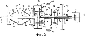
Система трансмиссии с бесступенчатым изменением передаточного отношения содержит вариатор V, относящийся к известному типу вариаторов с тороидальной рабочей поверхностью колес с фрикционными роликами, имеющему два диска 10 с тороидальными рабочими поверхностями, которые установлены по одному на каждом конце устройства, и пару подобных выходных дисков 12, каждый из которых обращен к соответствующему входному диску 10, и вращающихся один с другим. Между обращенными друг к другу рабочими поверхностями входных и выходных дисков 10, 12 установлен ряд роликов 14 для передачи вращения от входных дисков 10 к выходным дискам 12 с передаточным отношением, которое меняется посредством наклона роликов 14.The transmission system with a continuously variable gear ratio contains a variator V, related to the known type of variators with a toroidal working surface of the wheels with friction rollers, having two
Входные диски 10 соединены с входным валом 16 системы и приводятся от него. Выход вариатора осуществляется через трубчатый выходной вал 18 вариатора, который расположен соосно с входным валом 16. Конец вала 18, удаленный от вариатора V, приводит центральное зубчатое колесо S1 первого объединяющего планетарного редуктора Е1. Водило С1 планетарного редуктора Е1 соединено с входным валом 16 и приводится им, а также соединено с внутренним из двух входных дисков 10 вариатора. На водиле С1 установлены входные сателлиты Р1, которые находятся в зацеплении с центральным зубчатым колесом S1 и приводятся им. Каждый из сателлитов Р1 установлен на водиле С1 на соответствующем валу 20, на котором дополнительно установлены первый и второй выходные сателлиты РХ1 и PY1. Выходной сателлит РХ1 идентичен сателлиту Р1 и передает суммированный выход редуктора Е1 через выходное центральное зубчатое колесо S2 (того же размера, что и входное центральное зубчатое колесо S1) на промежуточный выходной вал 22, установленный соосно с входным валом 16 системы. Вращение от промежуточного выходного вала может выборочно передаваться через муфту Н режима высокого передаточного отношения на выходной вал 24 системы.The
Выходной сателлит PY1 имеет меньший диаметр, чем сателлиты Р1 и РХ1, и находится в зацеплении с шестерней 26, образованной на одном конце трубчатого промежуточного выходного вала 28, установленного соосно с выходным валом 16. Противоположные концы этого промежуточного выходного вала также снабжены шестерней 30, имеющей диаметр меньший, чем диаметр шестерни 26. Шестерня 30 находится в зацеплении с имеющими больший диаметр сателлитами Р2 второго простого реверсирующего планетарного редуктора D2. Сателлиты Р2 установлены на водиле С2, которое соединено со вторым трубчатым промежуточным выходным валом 32, установленным соосно с выходным валом 16 системы и, в свою очередь, соединенным с выходным валом 24 системы.The output satellite PY1 has a smaller diameter than the satellites P1 and PX1, and is engaged with a
Каждый сателлит Р2 второго планетарного редуктора расположен на одном конце соответствующего вала 34, установленного на водиле С2. На противоположном конце каждого вала 34 установлен еще один сателлит РХ2 меньшего диаметра, который находится в зацеплении с центральным зубчатым колесом 36, жестко соединенным с кожухом 40 трансмиссии. Вращение второго трубчатого промежуточного выходного вала 32 непрерывно отбирается от водила С2 и выборочно передается на выходной вал 24 системы через муфту L режима низкого передаточного отношения.Each satellite P2 of the second planetary gear is located at one end of the
Кроме того, следует отметить, что трубчатый промежуточный выходной вал 28 можно выборочно тормозить относительно кожуха 40 трансмиссии, упомянутой выше дополнительной муфтой В.In addition, it should be noted that the tubular
Трансмиссия может работать в одном из трех режимов, а именно: в режиме с высоким передаточным отношением, в режиме с низким передаточным отношением и в синхронном режиме.The transmission can operate in one of three modes, namely: in the mode with a high gear ratio, in the mode with a low gear ratio and in synchronous mode.
В режиме с высоким передаточным отношением муфта Н режима с высоким передаточным отношением включена, а муфта L режима с низким передаточным отношением выключена. Это обеспечивает передачу выхода первого объединяющего планетарного редуктора, образованного шестернями РХ1 и S2 и водилом С1, который получает на входе вращение как от входного диска 10, так и от выходного диска 12 вариатора V, на выходной вал 24 системы от выходных сателлитов РХ1 первого планетарного редуктора Е1, через выходное центральное зубчатое колесо S2, промежуточный выходной вал 22 и муфту Н режима с высоким передаточным отношением.In the high gear ratio mode, the high gear ratio clutch H is engaged and the low gear ratio clutch L is turned off. This ensures that the output of the first unifying planetary gearbox, formed by gears PX1 and S2 and carrier C1, which receives input from both the
Выход другого выходного сателлита PY1 первого объединяющего планетарного редуктора Е1 также передается на второй планетарный редуктор Е2. Этот выход не передается на водило С2 в режиме с высоким передаточным отношением, потому что муфта L режима с низким передаточным отношением выключена.The output of the other output satellite PY1 of the first unifying planetary gearbox E1 is also transmitted to the second planetary gearbox E2. This output is not transmitted to the carrier C2 in the high gear ratio mode, because the clutch L of the low gear ratio mode is turned off.
Однако, как было описано выше, для определенного состояния трансмиссии (известного как «зацепленная нейтраль») трубчатый промежуточный выходной вал 28 (т.е. второй выход объединяющего планетарного редуктора Е1) не вращается. Настоящее изобретение использует преимущество этой ситуации путем обнаружения состояния зацепленной нейтрали и включения муфты В для запирания промежуточного вала 28 относительно кожуха 40 трансмиссии в состоянии, в котором второй выход объединяющего планетарного редуктора, образованного шестернями S1, P1, PY1 и 26 и водилом С1, является неподвижным.However, as described above, for a certain transmission condition (known as “neutral gear”), the tubular intermediate output shaft 28 (i.e., the second output of the combining planetary gearbox E1) does not rotate. The present invention takes advantage of this situation by detecting a neutral neutral state and engaging clutch B to lock the
В результате этого, вариатор эффективно запирается на фиксированном передаточном отношении, соответствующем зацепленной нейтрали. Тогда, от входного вала 16 мощность передается с фиксированным передаточным отношением через первый объединяющий планетарный редуктор, образованный водилом С1 и парами зубчатых колес S2/PX1 и 26/PY1.As a result of this, the variator is effectively locked at a fixed gear ratio corresponding to the geared neutral. Then, power is transmitted from the
В режиме с низким передаточным отношением муфта Н режима с высоким передаточным отношением выключена, а муфта L режима с низким передаточным отношением включена. Выключение муфты Н режима с высоким передаточным отношением изолирует выходной вал 24 системы от выходного сателлита РХ1 объединяющего планетарного редуктора Е1. Кроме того, включение муфты L режима с низким передаточным отношением позволяет вращение выхода первого объединяющего планетарного редуктора Е1, подаваемое на второй планетарный редуктор Е2, передавать на водило С2 второго планетарного редуктора Е2 за счет реактивной силы от кожуха 40 трансмиссии. Затем вращение передается на второй трубчатый промежуточный выходной вал 32 и от него - на выходной вал 24 системы.In the low gear ratio mode, the high gear ratio clutch H is turned off, and the low gear clutch L of the mode with the low gear ratio is turned on. Switching off the mode H clutch with a high gear ratio isolates the
Переход с режима с низким передаточным отношением на режим с высоким передаточным отношением, и наоборот может выполняться в так называемом «синхронном режиме», в котором, трансмиссия работает в состоянии, при котором промежуточный выходной вал 22, ведущий от объединяющего планетарного редуктора Е1, и второй трубчатый промежуточный выходной вал 32, ведущий от второго планетарного редуктора Е2, вращаются с одинаковой (или очень близкой) частотой. Для того чтобы изменить режим, включают муфту нового режима, в результате чего в течение короткого времени муфты обоих режимов остаются включенными, и муфту старого режима затем выключают.The transition from the low gear ratio mode to the high gear ratio mode, and vice versa, can be performed in the so-called “synchronous mode”, in which the transmission operates in a state in which the
Следует отметить, что в режиме с низким передаточным отношением единственными шестернями, находящимися в активном зацеплении в объединяющем планетарном редукторе Е1, являются сателлиты Р1 и PY1, тем самым минимизируя потери, которые возникают в объединяющем планетарном редукторе, особенно в режиме рециркуляции мощности. В режиме с высоким передаточным отношением количество зацеплений не превышает это количество в трансмиссиях согласно предшествующему уровню техники. Однако следует также отметить, что настоящее изобретение позволяет использовать объединяющий планетарный редуктор Е1, который не имеет кольцевых шестерен или зубчатых венцов. Это не только снижает вес трансмиссии, но и обеспечивает бульшую гибкость при выборе относительных размеров сателлитов Р1, РХ1 и PY1. Это, в свою очередь, позволяет снизить частоту вращения деталей и уменьшить количество зацеплений до минимума.It should be noted that in the low gear ratio mode, the only gears that are actively engaged in the combining planetary gearbox E1 are the satellites P1 and PY1, thereby minimizing the losses that occur in the combining planetary gearbox, especially in the power recirculation mode. In the high gear ratio mode, the number of gears does not exceed this number in transmissions according to the prior art. However, it should also be noted that the present invention allows the use of a combining planetary gearbox E1, which does not have ring gears or ring gears. This not only reduces the weight of the transmission, but also provides greater flexibility in choosing the relative sizes of the satellites P1, PX1 and PY1. This, in turn, allows to reduce the frequency of rotation of parts and reduce the number of gears to a minimum.
Следует отметить, что настоящее изобретение не ограничено деталями вышеописанного варианта.It should be noted that the present invention is not limited to the details of the above embodiment.
Claims (8)
Applications Claiming Priority (2)
| Application Number | Priority Date | Filing Date | Title |
|---|---|---|---|
| GBGB0315408.5A GB0315408D0 (en) | 2003-07-01 | 2003-07-01 | Continuously variable ratio transmission system |
| GB0315408.5 | 2003-07-01 |
Publications (2)
| Publication Number | Publication Date |
|---|---|
| RU2006101863A RU2006101863A (en) | 2006-06-10 |
| RU2338938C2 true RU2338938C2 (en) | 2008-11-20 |
Family
ID=27676463
Family Applications (1)
| Application Number | Title | Priority Date | Filing Date |
|---|---|---|---|
| RU2006101863/11A RU2338938C2 (en) | 2003-07-01 | 2004-07-01 | Stepless gear ratio variation transmission |
Country Status (13)
| Country | Link |
|---|---|
| US (1) | US7530916B2 (en) |
| EP (1) | EP1639273B1 (en) |
| JP (1) | JP2007516385A (en) |
| KR (1) | KR20060034251A (en) |
| CN (1) | CN100582528C (en) |
| AT (1) | ATE410622T1 (en) |
| BR (1) | BRPI0411997A (en) |
| CA (1) | CA2529885A1 (en) |
| DE (1) | DE602004016997D1 (en) |
| GB (1) | GB0315408D0 (en) |
| MX (1) | MXPA05014097A (en) |
| RU (1) | RU2338938C2 (en) |
| WO (1) | WO2005003597A1 (en) |
Families Citing this family (39)
| Publication number | Priority date | Publication date | Assignee | Title |
|---|---|---|---|---|
| RU2307272C2 (en) * | 2002-05-28 | 2007-09-27 | Торотрак (Дивелопмент) Лимитед | System of transmission with constantly changing gear ratio |
| JP4720370B2 (en) * | 2005-08-24 | 2011-07-13 | 株式会社エクォス・リサーチ | Continuously variable transmission |
| GB0703351D0 (en) | 2007-02-21 | 2007-03-28 | Torotrak Dev Ltd | Continuously variable transmission |
| GB0709635D0 (en) * | 2007-05-19 | 2007-06-27 | Valtra Inc | Rotation sensing |
| GB0717143D0 (en) * | 2007-09-04 | 2007-10-17 | Torotrak Dev Ltd | Continuously variable transmission |
| US20100240491A1 (en) * | 2009-03-17 | 2010-09-23 | Parag Vyas | System for vehicle propulsion having and method of making same |
| US8535200B2 (en) * | 2009-03-17 | 2013-09-17 | General Electric Company | Vehicle propulsion system having a continuously variable transmission and method of making same |
| US8676515B2 (en) | 2009-12-16 | 2014-03-18 | Allison Transmission, Inc. | System and method for detecting clutch-related faults in an automatic transmission |
| US8401752B2 (en) | 2009-12-16 | 2013-03-19 | Allison Transmission, Inc. | Fail-to-neutral system and method for a toroidal traction drive automatic transmission |
| US8578802B2 (en) | 2009-12-16 | 2013-11-12 | Allison Transmission, Inc. | System and method for multiplexing gear engagement control and providing fault protection in a toroidal traction drive automatic transmission |
| EP2512892B1 (en) * | 2009-12-16 | 2019-01-09 | Allison Transmission, Inc. | Variator fault detection system |
| US8744697B2 (en) | 2009-12-16 | 2014-06-03 | Allison Transmission, Inc. | Variator lockout valve system |
| KR20120106976A (en) * | 2009-12-16 | 2012-09-27 | 알리손 트랜스미션, 인크. | System and method for controlling endload force of a variator |
| EP2513523A4 (en) | 2009-12-16 | 2016-07-06 | Allison Transm Inc | Fast valve actuation system for an automatic transmission |
| EP2606258B1 (en) | 2010-08-16 | 2020-08-05 | Allison Transmission, Inc. | Gear scheme for infinitely variable transmission |
| US8840522B2 (en) | 2010-12-15 | 2014-09-23 | Allison Transmission, Inc. | Variator switching valve scheme for a torroidal traction drive transmision |
| CN103370562B (en) | 2010-12-15 | 2016-03-23 | 艾里逊变速箱公司 | For controlling to equipment and the method for the fluid stream of gear in automatic transmission |
| WO2012082843A1 (en) | 2010-12-15 | 2012-06-21 | Long Charles F | Dual pump regulator system for a motor vehicle transmission |
| CA2830929A1 (en) | 2011-04-04 | 2012-10-11 | Fallbrook Intellectual Property Company Llc | Auxiliary power unit having a continuously variable transmission |
| WO2013052425A2 (en) | 2011-10-03 | 2013-04-11 | Fallbrook Intellectual Property Company Llc | Refrigeration system having a continuously variable transmission |
| WO2013109723A1 (en) | 2012-01-19 | 2013-07-25 | Dana Limited | Tilting ball variator continuously variable transmission torque vectoring device |
| US8579753B2 (en) * | 2012-02-10 | 2013-11-12 | GM Global Technology Operations LLC | Compound planetary front wheel drive continuously variable transmission |
| EP2815152A1 (en) | 2012-02-15 | 2014-12-24 | Dana Limited | Transmission and driveline having a tilting ball variator continuously variable transmission |
| EP2893219A4 (en) | 2012-09-06 | 2016-12-28 | Dana Ltd | Transmission having a continuously or infinitely variable variator drive |
| JP6293148B2 (en) | 2012-09-07 | 2018-03-14 | デーナ リミテッド | Ball CVT including direct drive mode |
| WO2014039713A1 (en) | 2012-09-07 | 2014-03-13 | Dana Limited | Ivt based on a ball type cvp including powersplit paths |
| WO2014039439A1 (en) | 2012-09-07 | 2014-03-13 | Dana Limited | Ball type cvt/ivt including planetary gear sets |
| JP6247691B2 (en) | 2012-09-07 | 2017-12-13 | デーナ リミテッド | Ball type continuously variable transmission / continuously variable transmission |
| US9353842B2 (en) | 2012-09-07 | 2016-05-31 | Dana Limited | Ball type CVT with powersplit paths |
| JP6247690B2 (en) | 2012-09-07 | 2017-12-13 | デーナ リミテッド | Ball CVT with output connection power path |
| US10030748B2 (en) | 2012-11-17 | 2018-07-24 | Dana Limited | Continuously variable transmission |
| WO2014124063A1 (en) | 2013-02-08 | 2014-08-14 | Microsoft Corporation | Pervasive service providing device-specific updates |
| WO2014159756A2 (en) | 2013-03-14 | 2014-10-02 | Dana Limited | Continuously variable transmission and an infinitely variable transmission variatory drive |
| WO2014159755A2 (en) | 2013-03-14 | 2014-10-02 | Dana Limited | Ball type continuously variable transmission |
| JP2016520782A (en) | 2013-06-06 | 2016-07-14 | デーナ リミテッド | 3 mode front wheel drive and rear wheel drive continuously variable planetary transmission |
| US10030751B2 (en) | 2013-11-18 | 2018-07-24 | Dana Limited | Infinite variable transmission with planetary gear set |
| WO2015073948A2 (en) | 2013-11-18 | 2015-05-21 | Dana Limited | Torque peak detection and control mechanism for cvp |
| US10030594B2 (en) | 2015-09-18 | 2018-07-24 | Dana Limited | Abuse mode torque limiting control method for a ball-type continuously variable transmission |
| WO2017145178A1 (en) * | 2016-02-23 | 2017-08-31 | B R Girish | Continuously variable transmission system using differential and brake |
Family Cites Families (6)
| Publication number | Priority date | Publication date | Assignee | Title |
|---|---|---|---|---|
| DE19703544A1 (en) * | 1997-01-31 | 1998-08-06 | Zahnradfabrik Friedrichshafen | Friction gear |
| JP3702597B2 (en) * | 1997-08-12 | 2005-10-05 | 日本精工株式会社 | Toroidal type continuously variable transmission |
| JP3697860B2 (en) * | 1997-10-07 | 2005-09-21 | 日本精工株式会社 | Toroidal type continuously variable transmission |
| JP4062809B2 (en) * | 1999-02-03 | 2008-03-19 | 日本精工株式会社 | Continuously variable transmission |
| DE10121042C1 (en) * | 2001-04-28 | 2003-05-08 | Daimler Chrysler Ag | Change gear arrangement with a toroidal continuously variable transmission and a planetary gear total gear |
| RU2307272C2 (en) * | 2002-05-28 | 2007-09-27 | Торотрак (Дивелопмент) Лимитед | System of transmission with constantly changing gear ratio |
-
2003
- 2003-07-01 GB GBGB0315408.5A patent/GB0315408D0/en not_active Ceased
-
2004
- 2004-07-01 BR BRPI0411997-5A patent/BRPI0411997A/en not_active IP Right Cessation
- 2004-07-01 DE DE602004016997T patent/DE602004016997D1/en active Active
- 2004-07-01 EP EP04743188A patent/EP1639273B1/en active Active
- 2004-07-01 WO PCT/GB2004/002841 patent/WO2005003597A1/en active Application Filing
- 2004-07-01 CA CA002529885A patent/CA2529885A1/en not_active Abandoned
- 2004-07-01 AT AT04743188T patent/ATE410622T1/en not_active IP Right Cessation
- 2004-07-01 US US10/561,727 patent/US7530916B2/en active Active
- 2004-07-01 KR KR1020057025444A patent/KR20060034251A/en not_active Application Discontinuation
- 2004-07-01 JP JP2006516488A patent/JP2007516385A/en active Pending
- 2004-07-01 MX MXPA05014097A patent/MXPA05014097A/en active IP Right Grant
- 2004-07-01 CN CN200480018840A patent/CN100582528C/en not_active Expired - Fee Related
- 2004-07-01 RU RU2006101863/11A patent/RU2338938C2/en not_active IP Right Cessation
Also Published As
| Publication number | Publication date |
|---|---|
| MXPA05014097A (en) | 2006-03-17 |
| GB0315408D0 (en) | 2003-08-06 |
| US20070042856A1 (en) | 2007-02-22 |
| DE602004016997D1 (en) | 2008-11-20 |
| EP1639273A1 (en) | 2006-03-29 |
| JP2007516385A (en) | 2007-06-21 |
| KR20060034251A (en) | 2006-04-21 |
| BRPI0411997A (en) | 2006-09-05 |
| EP1639273B1 (en) | 2008-10-08 |
| US7530916B2 (en) | 2009-05-12 |
| RU2006101863A (en) | 2006-06-10 |
| CN100582528C (en) | 2010-01-20 |
| CA2529885A1 (en) | 2005-01-13 |
| WO2005003597A1 (en) | 2005-01-13 |
| ATE410622T1 (en) | 2008-10-15 |
| CN1820155A (en) | 2006-08-16 |
Similar Documents
| Publication | Publication Date | Title |
|---|---|---|
| RU2338938C2 (en) | Stepless gear ratio variation transmission | |
| RU2307272C2 (en) | System of transmission with constantly changing gear ratio | |
| KR100289108B1 (en) | Continuously variable-ratio transmission | |
| RU2487284C2 (en) | Infinitely variable transmission | |
| EP0502061B1 (en) | Transmission of the toroidal-race rolling-traction type | |
| US20020169048A1 (en) | Speed change transmission arrangement including a continuously variable toriodal transmission | |
| EP1800026A1 (en) | Continuously variable ratio transmission system | |
| WO2006103294A1 (en) | Continuously variable transmission | |
| EP0452382B1 (en) | Driveline for wheeled vehicles | |
| AU8412391A (en) | Improvements in or relating to transmissions of the toroidal-race, rolling-traction type | |
| WO2006132954A1 (en) | Multi-range hydromechanical transmission and method of operation | |
| GB2384531A (en) | Multi-regime CVT with coaxial input and output shafts | |
| EP0409852B1 (en) | Continuously variable transmissions | |
| GB2410302A (en) | Multi-regime CVT with coaxial input and output shafts | |
| GB2397630A (en) | A multi-regime CVT system with coaxial input and output shafts | |
| JP2007016912A (en) | Continuously variable transmission | |
| US5288281A (en) | Contiuously variable transmissions | |
| JPH1163154A (en) | Hydromechanical transmission | |
| JP4894698B2 (en) | Continuously variable transmission | |
| JP2006316839A (en) | Continuously variable transmission device | |
| JPH11230308A (en) | Hydro-mechanical transmission | |
| JP2008025795A (en) | Continuously variable transmission device | |
| KR980010035A (en) | Belt pulley type continuously variable transmission | |
| JP2007170600A (en) | Continuously variable transmission device | |
| JP2013087780A (en) | Continuously variable transmission |
Legal Events
| Date | Code | Title | Description |
|---|---|---|---|
| MM4A | The patent is invalid due to non-payment of fees |
Effective date: 20110702 |