JP6247691B2 - Ball type continuously variable transmission / continuously variable transmission - Google Patents
Ball type continuously variable transmission / continuously variable transmission Download PDFInfo
- Publication number
- JP6247691B2 JP6247691B2 JP2015531260A JP2015531260A JP6247691B2 JP 6247691 B2 JP6247691 B2 JP 6247691B2 JP 2015531260 A JP2015531260 A JP 2015531260A JP 2015531260 A JP2015531260 A JP 2015531260A JP 6247691 B2 JP6247691 B2 JP 6247691B2
- Authority
- JP
- Japan
- Prior art keywords
- continuously variable
- brake
- variator
- variable mode
- mode
- Prior art date
- Legal status (The legal status is an assumption and is not a legal conclusion. Google has not performed a legal analysis and makes no representation as to the accuracy of the status listed.)
- Expired - Fee Related
Links
Images


Classifications
-
- F—MECHANICAL ENGINEERING; LIGHTING; HEATING; WEAPONS; BLASTING
- F16—ENGINEERING ELEMENTS AND UNITS; GENERAL MEASURES FOR PRODUCING AND MAINTAINING EFFECTIVE FUNCTIONING OF MACHINES OR INSTALLATIONS; THERMAL INSULATION IN GENERAL
- F16H—GEARING
- F16H15/00—Gearings for conveying rotary motion with variable gear ratio, or for reversing rotary motion, by friction between rotary members
- F16H15/48—Gearings for conveying rotary motion with variable gear ratio, or for reversing rotary motion, by friction between rotary members with members having orbital motion
- F16H15/50—Gearings providing a continuous range of gear ratios
- F16H15/52—Gearings providing a continuous range of gear ratios in which a member of uniform effective diameter mounted on a shaft may co-operate with different parts of another member
-
- F—MECHANICAL ENGINEERING; LIGHTING; HEATING; WEAPONS; BLASTING
- F16—ENGINEERING ELEMENTS AND UNITS; GENERAL MEASURES FOR PRODUCING AND MAINTAINING EFFECTIVE FUNCTIONING OF MACHINES OR INSTALLATIONS; THERMAL INSULATION IN GENERAL
- F16H—GEARING
- F16H15/00—Gearings for conveying rotary motion with variable gear ratio, or for reversing rotary motion, by friction between rotary members
- F16H15/48—Gearings for conveying rotary motion with variable gear ratio, or for reversing rotary motion, by friction between rotary members with members having orbital motion
- F16H15/50—Gearings providing a continuous range of gear ratios
- F16H15/503—Gearings providing a continuous range of gear ratios in which two members co-operate by means of balls or rollers of uniform effective diameter, not mounted on shafts
-
- F—MECHANICAL ENGINEERING; LIGHTING; HEATING; WEAPONS; BLASTING
- F16—ENGINEERING ELEMENTS AND UNITS; GENERAL MEASURES FOR PRODUCING AND MAINTAINING EFFECTIVE FUNCTIONING OF MACHINES OR INSTALLATIONS; THERMAL INSULATION IN GENERAL
- F16H—GEARING
- F16H37/00—Combinations of mechanical gearings, not provided for in groups F16H1/00 - F16H35/00
- F16H37/02—Combinations of mechanical gearings, not provided for in groups F16H1/00 - F16H35/00 comprising essentially only toothed or friction gearings
- F16H37/021—Combinations of mechanical gearings, not provided for in groups F16H1/00 - F16H35/00 comprising essentially only toothed or friction gearings toothed gearing combined with continuous variable friction gearing
- F16H37/022—Combinations of mechanical gearings, not provided for in groups F16H1/00 - F16H35/00 comprising essentially only toothed or friction gearings toothed gearing combined with continuous variable friction gearing the toothed gearing having orbital motion
-
- F—MECHANICAL ENGINEERING; LIGHTING; HEATING; WEAPONS; BLASTING
- F16—ENGINEERING ELEMENTS AND UNITS; GENERAL MEASURES FOR PRODUCING AND MAINTAINING EFFECTIVE FUNCTIONING OF MACHINES OR INSTALLATIONS; THERMAL INSULATION IN GENERAL
- F16H—GEARING
- F16H37/00—Combinations of mechanical gearings, not provided for in groups F16H1/00 - F16H35/00
- F16H37/02—Combinations of mechanical gearings, not provided for in groups F16H1/00 - F16H35/00 comprising essentially only toothed or friction gearings
- F16H37/06—Combinations of mechanical gearings, not provided for in groups F16H1/00 - F16H35/00 comprising essentially only toothed or friction gearings with a plurality of driving or driven shafts; with arrangements for dividing torque between two or more intermediate shafts
- F16H37/08—Combinations of mechanical gearings, not provided for in groups F16H1/00 - F16H35/00 comprising essentially only toothed or friction gearings with a plurality of driving or driven shafts; with arrangements for dividing torque between two or more intermediate shafts with differential gearing
- F16H37/0833—Combinations of mechanical gearings, not provided for in groups F16H1/00 - F16H35/00 comprising essentially only toothed or friction gearings with a plurality of driving or driven shafts; with arrangements for dividing torque between two or more intermediate shafts with differential gearing with arrangements for dividing torque between two or more intermediate shafts, i.e. with two or more internal power paths
- F16H37/084—Combinations of mechanical gearings, not provided for in groups F16H1/00 - F16H35/00 comprising essentially only toothed or friction gearings with a plurality of driving or driven shafts; with arrangements for dividing torque between two or more intermediate shafts with differential gearing with arrangements for dividing torque between two or more intermediate shafts, i.e. with two or more internal power paths at least one power path being a continuously variable transmission, i.e. CVT
- F16H37/0853—CVT using friction between rotary members having a first member of uniform effective diameter cooperating with different parts of a second member
-
- F—MECHANICAL ENGINEERING; LIGHTING; HEATING; WEAPONS; BLASTING
- F16—ENGINEERING ELEMENTS AND UNITS; GENERAL MEASURES FOR PRODUCING AND MAINTAINING EFFECTIVE FUNCTIONING OF MACHINES OR INSTALLATIONS; THERMAL INSULATION IN GENERAL
- F16H—GEARING
- F16H37/00—Combinations of mechanical gearings, not provided for in groups F16H1/00 - F16H35/00
- F16H37/02—Combinations of mechanical gearings, not provided for in groups F16H1/00 - F16H35/00 comprising essentially only toothed or friction gearings
- F16H37/021—Combinations of mechanical gearings, not provided for in groups F16H1/00 - F16H35/00 comprising essentially only toothed or friction gearings toothed gearing combined with continuous variable friction gearing
- F16H2037/026—CVT layouts with particular features of reversing gear, e.g. to achieve compact arrangement
-
- F—MECHANICAL ENGINEERING; LIGHTING; HEATING; WEAPONS; BLASTING
- F16—ENGINEERING ELEMENTS AND UNITS; GENERAL MEASURES FOR PRODUCING AND MAINTAINING EFFECTIVE FUNCTIONING OF MACHINES OR INSTALLATIONS; THERMAL INSULATION IN GENERAL
- F16H—GEARING
- F16H37/00—Combinations of mechanical gearings, not provided for in groups F16H1/00 - F16H35/00
- F16H37/02—Combinations of mechanical gearings, not provided for in groups F16H1/00 - F16H35/00 comprising essentially only toothed or friction gearings
- F16H37/06—Combinations of mechanical gearings, not provided for in groups F16H1/00 - F16H35/00 comprising essentially only toothed or friction gearings with a plurality of driving or driven shafts; with arrangements for dividing torque between two or more intermediate shafts
- F16H37/08—Combinations of mechanical gearings, not provided for in groups F16H1/00 - F16H35/00 comprising essentially only toothed or friction gearings with a plurality of driving or driven shafts; with arrangements for dividing torque between two or more intermediate shafts with differential gearing
- F16H37/0833—Combinations of mechanical gearings, not provided for in groups F16H1/00 - F16H35/00 comprising essentially only toothed or friction gearings with a plurality of driving or driven shafts; with arrangements for dividing torque between two or more intermediate shafts with differential gearing with arrangements for dividing torque between two or more intermediate shafts, i.e. with two or more internal power paths
- F16H37/084—Combinations of mechanical gearings, not provided for in groups F16H1/00 - F16H35/00 comprising essentially only toothed or friction gearings with a plurality of driving or driven shafts; with arrangements for dividing torque between two or more intermediate shafts with differential gearing with arrangements for dividing torque between two or more intermediate shafts, i.e. with two or more internal power paths at least one power path being a continuously variable transmission, i.e. CVT
- F16H2037/0866—Power split variators with distributing differentials, with the output of the CVT connected or connectable to the output shaft
- F16H2037/0873—Power split variators with distributing differentials, with the output of the CVT connected or connectable to the output shaft with switching, e.g. to change ranges
-
- F—MECHANICAL ENGINEERING; LIGHTING; HEATING; WEAPONS; BLASTING
- F16—ENGINEERING ELEMENTS AND UNITS; GENERAL MEASURES FOR PRODUCING AND MAINTAINING EFFECTIVE FUNCTIONING OF MACHINES OR INSTALLATIONS; THERMAL INSULATION IN GENERAL
- F16H—GEARING
- F16H37/00—Combinations of mechanical gearings, not provided for in groups F16H1/00 - F16H35/00
- F16H37/02—Combinations of mechanical gearings, not provided for in groups F16H1/00 - F16H35/00 comprising essentially only toothed or friction gearings
- F16H37/06—Combinations of mechanical gearings, not provided for in groups F16H1/00 - F16H35/00 comprising essentially only toothed or friction gearings with a plurality of driving or driven shafts; with arrangements for dividing torque between two or more intermediate shafts
- F16H37/08—Combinations of mechanical gearings, not provided for in groups F16H1/00 - F16H35/00 comprising essentially only toothed or friction gearings with a plurality of driving or driven shafts; with arrangements for dividing torque between two or more intermediate shafts with differential gearing
- F16H37/0833—Combinations of mechanical gearings, not provided for in groups F16H1/00 - F16H35/00 comprising essentially only toothed or friction gearings with a plurality of driving or driven shafts; with arrangements for dividing torque between two or more intermediate shafts with differential gearing with arrangements for dividing torque between two or more intermediate shafts, i.e. with two or more internal power paths
- F16H37/084—Combinations of mechanical gearings, not provided for in groups F16H1/00 - F16H35/00 comprising essentially only toothed or friction gearings with a plurality of driving or driven shafts; with arrangements for dividing torque between two or more intermediate shafts with differential gearing with arrangements for dividing torque between two or more intermediate shafts, i.e. with two or more internal power paths at least one power path being a continuously variable transmission, i.e. CVT
- F16H2037/0893—Combinations of mechanical gearings, not provided for in groups F16H1/00 - F16H35/00 comprising essentially only toothed or friction gearings with a plurality of driving or driven shafts; with arrangements for dividing torque between two or more intermediate shafts with differential gearing with arrangements for dividing torque between two or more intermediate shafts, i.e. with two or more internal power paths at least one power path being a continuously variable transmission, i.e. CVT characterised in the ratio of the continuously variable transmission is different from zero when the output shaft speed is zero
-
- F—MECHANICAL ENGINEERING; LIGHTING; HEATING; WEAPONS; BLASTING
- F16—ENGINEERING ELEMENTS AND UNITS; GENERAL MEASURES FOR PRODUCING AND MAINTAINING EFFECTIVE FUNCTIONING OF MACHINES OR INSTALLATIONS; THERMAL INSULATION IN GENERAL
- F16H—GEARING
- F16H2200/00—Transmissions for multiple ratios
- F16H2200/20—Transmissions using gears with orbital motion
- F16H2200/2002—Transmissions using gears with orbital motion characterised by the number of sets of orbital gears
- F16H2200/2007—Transmissions using gears with orbital motion characterised by the number of sets of orbital gears with two sets of orbital gears
-
- F—MECHANICAL ENGINEERING; LIGHTING; HEATING; WEAPONS; BLASTING
- F16—ENGINEERING ELEMENTS AND UNITS; GENERAL MEASURES FOR PRODUCING AND MAINTAINING EFFECTIVE FUNCTIONING OF MACHINES OR INSTALLATIONS; THERMAL INSULATION IN GENERAL
- F16H—GEARING
- F16H2200/00—Transmissions for multiple ratios
- F16H2200/20—Transmissions using gears with orbital motion
- F16H2200/203—Transmissions using gears with orbital motion characterised by the engaging friction means not of the freewheel type, e.g. friction clutches or brakes
- F16H2200/2035—Transmissions using gears with orbital motion characterised by the engaging friction means not of the freewheel type, e.g. friction clutches or brakes with two engaging means
Description
(関連出願)
本願は、米国仮出願第61/698,005号(2012年9月7日出願)、米国仮出願第61/782,924号(2013年3月14日出願)の利益を主張し、これらの出願は、それらの全体が参照により本明細書に引用される。
(Related application)
This application claims the benefit of US Provisional Application No. 61 / 698,005 (filed September 7, 2012), US Provisional Application No. 61 / 782,924 (filed March 14, 2013), and Applications are hereby incorporated by reference in their entirety.
自動および手動トランスミッションは、一般に、自動車車両上で使用される。それらのトランスミッションは、エンジン回転数が、車の消費量および排出量を制限するためにより精密に制御される必要があるため、ますます複雑になりつつある。通常のトランスミッションにおけるエンジン回転数のより微妙な制御は、より離散した段階比のギヤを追加し、全体的複雑性およびコストを増加することのみによって、行われることができる。その結果、6速手動トランスミッションは、したがって、8または9速自動トランスミッションと同じくらい頻繁に使用される。 Automatic and manual transmissions are commonly used on automobile vehicles. These transmissions are becoming increasingly complex because the engine speed needs to be more precisely controlled to limit vehicle consumption and emissions. More subtle control of engine speed in a normal transmission can be done only by adding more discrete step ratio gears and increasing overall complexity and cost. As a result, 6-speed manual transmissions are therefore used as frequently as 8- or 9-speed automatic transmissions.
本明細書に提供されるのは、動力入力シャフトと、動力入力シャフトに機械的に連結される遊星ギヤセットと、バリエータキャリアアセンブリ、第1のリングアセンブリ、および第2のリングアセンブリを備えている、バリエータと、ブレーキおよびクラッチの種々の組み合わせとを備えている、可変トランスミッションである。 Provided herein includes a power input shaft, a planetary gear set mechanically coupled to the power input shaft, a variator carrier assembly, a first ring assembly, and a second ring assembly. A variable transmission comprising a variator and various combinations of brakes and clutches.
本明細書に開示される実施形態のいずれかにおいて、可変トランスミッションは、連続可変トランスミッションであり得る。 In any of the embodiments disclosed herein, the variable transmission can be a continuously variable transmission.
いくつかの実施形態では、可変トランスミッションは、連続可変モード、無段可変モード、またはそれらの組み合わせを有する、バリエータを備えている。 In some embodiments, the variable transmission includes a variator that has a continuously variable mode, a continuously variable mode, or a combination thereof.
いくつかの実施形態では、可変トランスミッションは、逆進機能、静止機能、および低速機能を提供することができる。 In some embodiments, the variable transmission can provide a reverse function, a stationary function, and a low speed function.
いくつかの実施形態では、連続可変トランスミッションモードと無段可変トランスミッションモードとの間の遷移は、同時に、ブレーキの一方を解放し、他方のブレーキを適用することによって達成される。 In some embodiments, the transition between the continuously variable transmission mode and the continuously variable transmission mode is accomplished by simultaneously releasing one of the brakes and applying the other brake.
いくつかの実施形態では、連続可変トランスミッションモードと無段可変トランスミッションモードとの間の遷移は、クラッチを解放し、ブレーキを係合することによって達成される。 In some embodiments, the transition between continuously variable transmission mode and continuously variable transmission mode is achieved by disengaging the clutch and engaging the brake.
いくつかの実施形態では、バリエータは、連続可変モードおよび無段可変モードの両方において、連続的にそのトルク比を変化させ、エンジンのために利用可能な最良比を提供し、性能または燃料消費を最適化することが可能である。 In some embodiments, the variator continuously changes its torque ratio in both continuously variable and continuously variable modes, providing the best available ratio for the engine, and improving performance or fuel consumption. It is possible to optimize.
本明細書に提供されるのは、可変トランスミッションであって、入力シャフトと、遊星ギヤセットであって、遊星ギヤセットのキャリアは、入力シャフトと駆動係合される、遊星ギヤセットと、遊星ギヤセットのリングギヤに機械的に連結されている第1のブレーキと、バリエータキャリアアセンブリ、第1のリングアセンブリ、および第2のリングアセンブリを備えているバリエータであって、バリエータキャリアアセンブリは、遊星ギヤセットのリングギヤに機械的に連結される、バリエータと、遊星ギヤセットの太陽ギヤおよびバリエータの第1のリングアセンブリに機械的に連結されている第2のブレーキとを備え、バリエータの第2のリングアセンブリアセンブリは、可変トランスミッションの出力に駆動係合される、可変トランスミッションである。 Provided herein is a variable transmission comprising an input shaft and a planetary gear set, wherein the carrier of the planetary gear set is drivingly engaged with the input shaft to the planetary gear set and the ring gear of the planetary gear set. A variator comprising a first mechanically coupled brake and a variator carrier assembly, a first ring assembly, and a second ring assembly, wherein the variator carrier assembly is mechanically coupled to the ring gear of the planetary gear set. And a second brake mechanically coupled to the sun gear of the planetary gear set and the first ring assembly of the variator, wherein the second ring assembly assembly of the variator comprises the variable transmission A variable transformer that is drivingly engaged with the output Is a mission.
いくつかの実施形態では、可変トランスミッションは、連続可変モードおよび無段可変モードを備えている。いくつかの実施形態では、第1のブレーキが係合され、第2のブレーキが係合解除されると、遊星ギヤセットのリングギヤおよびバリエータキャリアアセンブリは、固定して保持され、それによって、連続可変モードを係合する。いくつかの実施形態では、トランスミッションが連続可変モードにあるとき、動力は、遊星ギヤセットの太陽ギヤを通して、第1のリングアセンブリへと渡る。 In some embodiments, the variable transmission has a continuously variable mode and a continuously variable mode. In some embodiments, when the first brake is engaged and the second brake is disengaged, the ring gear and variator carrier assembly of the planetary gear set is held fixed, thereby enabling a continuously variable mode. Engage. In some embodiments, when the transmission is in continuously variable mode, power passes through the sun gear of the planetary gear set to the first ring assembly.
いくつかの実施形態では、第2のブレーキが係合され、第1のブレーキが係合解除されると、遊星ギヤセットの太陽ギヤおよび第1のリングアセンブリは、固定して保持され、それによって、無段可変モードを係合する。いくつかの実施形態では、動力は、無段可変モードでは、遊星ギヤセットのリングギヤを通して、バリエータキャリアアセンブリへと渡る。いくつかの実施形態では、無段可変モードでは、バリエータは、逆進機能、静止機能、および低速機能を提供する。 In some embodiments, when the second brake is engaged and the first brake is disengaged, the sun gear and the first ring assembly of the planetary gear set are held securely, thereby Engage continuously variable mode. In some embodiments, power passes through the ring gear of the planetary gear set to the variator carrier assembly in the continuously variable mode. In some embodiments, in the continuously variable mode, the variator provides a reverse function, a stationary function, and a low speed function.
いくつかの実施形態では、連続可変モードと無段可変モードとの間の遷移は、同時に、第1のブレーキおよび第2のブレーキのうちの一方を解放しながら、第1のブレーキおよび第2のブレーキのうちの他方を適用することによって達成される。いくつかの実施形態では、バリエータは、連続可変モードおよび無段可変モードの両方において、連続的にそのトルク比を変化させ、性能または燃料消費を最適化する。いくつかの実施形態では、バリエータは、連続可変モードおよび無段可変モードの両方において、連続的にそのトルク比を変化させ、可変トランスミッションのための理想的比を達成する。 In some embodiments, the transition between continuously variable mode and continuously variable mode simultaneously releases the first brake and the second brake while releasing one of the first brake and the second brake. This is accomplished by applying the other of the brakes. In some embodiments, the variator continuously changes its torque ratio in both continuously variable and continuously variable modes to optimize performance or fuel consumption. In some embodiments, the variator continuously changes its torque ratio in both continuously variable and continuously variable modes to achieve an ideal ratio for a variable transmission.
いくつかの実施形態では、連続可変モードと無段可変モードとは、第2のリングアセンブリの回転速度において間隙をもたらす。一実施形態では、間隙は、エンジン速度調節によって補償される。いくつかの実施形態では、連続可変モードにおける第2のリングアセンブリの回転速度および無段可変モードにおける第2のリングアセンブリの回転速度と、エンジンからの入力シャフトの回転速度との関係は、図5に示されるようなものである。 In some embodiments, the continuously variable mode and the continuously variable mode provide a gap at the rotational speed of the second ring assembly. In one embodiment, the gap is compensated by engine speed adjustment. In some embodiments, the relationship between the rotational speed of the second ring assembly in the continuously variable mode and the rotational speed of the second ring assembly in the continuously variable mode and the rotational speed of the input shaft from the engine is shown in FIG. As shown in
いくつかの実施形態では、ギヤボックスは、以前に存在した間隙が、エンジン速度調節を伴わずに、完全に補完され得るように追加される。ギヤボックスは、可変トランスミッションにおける比、係合されるクラッチ、およびギヤボックス比を適切に選択することによって、最大逆進速度から最大前進速度に速度を連続的に変動させることを可能にする。そのようなギヤボックスはまた、実施形態の可変トランスミッション出力において、最大前進速度と逆進速度との間の広がり(spread)を増加させることを可能にし得る。 In some embodiments, the gearbox is added so that the previously existing clearance can be fully complemented without engine speed adjustment. The gearbox allows the speed to be continuously varied from the maximum reverse speed to the maximum forward speed by appropriately selecting the ratio in the variable transmission, the clutch to be engaged, and the gearbox ratio. Such a gearbox may also allow to increase the spread between maximum forward speed and reverse speed at the variable transmission output of the embodiment.
本明細書に提供されるのは、可変トランスミッションであって、入力シャフトと、遊星ギヤセットであって、遊星ギヤセットのリングギヤは、入力シャフトと駆動係合される、遊星ギヤセットと、バリエータキャリアアセンブリ、第1のリングアセンブリ、および第2のリングアセンブリを備えている、バリエータと、第1のブレーキおよび第2のリングアセンブリに連結される遊星ギヤセットの遊星ギヤキャリアと、第2のブレーキおよびバリエータキャリアアセンブリに連結される遊星ギヤセットの太陽ギヤとを備え、バリエータの第2のリングアセンブリは、可変トランスミッションの出力に駆動係合される、可変トランスミッションである。 Provided herein is a variable transmission, an input shaft and a planetary gear set, wherein the ring gear of the planetary gear set is drivingly engaged with the input shaft, the planetary gear set, the variator carrier assembly, the first A variator comprising a first ring assembly and a second ring assembly; a planetary gear carrier of a planetary gear set coupled to the first brake and the second ring assembly; and a second brake and variator carrier assembly. The planetary gear set sun gear connected to the second ring assembly of the variator is a variable transmission that is drivingly engaged to the output of the variable transmission.
いくつかの実施形態では、可変トランスミッションは、連続可変モードおよび無段可変モードを備えている。 In some embodiments, the variable transmission has a continuously variable mode and a continuously variable mode.
いくつかの実施形態では、第2のブレーキが係合され、第1のブレーキが係合解除されると、遊星ギヤセットの太陽ギヤは、バリエータキャリアアセンブリとともに固定され、連続可変モードを係合する。いくつかの実施形態では、トランスミッションが連続可変モードにあるとき、入力動力は、遊星ギヤセットのリングギヤを通して、第1のリングアセンブリへと渡る。 In some embodiments, when the second brake is engaged and the first brake is disengaged, the sun gear of the planetary gear set is secured with the variator carrier assembly and engages the continuously variable mode. In some embodiments, when the transmission is in the continuously variable mode, input power passes through the ring gear of the planetary gear set to the first ring assembly.
いくつかの実施形態では、第1のブレーキが係合され、第2のブレーキが係合解除されると、バリエータの第1のリングアセンブリおよび遊星ギヤキャリアは、固定して保持され、無段可変モードを係合する。いくつかの実施形態では、無段可変モードでは、バリエータは、逆進機能、静止機能、および低速機能を提供する。 In some embodiments, when the first brake is engaged and the second brake is disengaged, the first ring assembly of the variator and the planetary gear carrier are held fixed and continuously variable. Engage mode. In some embodiments, in the continuously variable mode, the variator provides a reverse function, a stationary function, and a low speed function.
いくつかの実施形態では、連続可変モードと無段可変モードとの間の遷移は、同時に、第1のブレーキおよび第2のブレーキのうちの一方を解放しながら、第1のブレーキおよび第2のブレーキのうちの他方を適用することによって達成される。 In some embodiments, the transition between continuously variable mode and continuously variable mode simultaneously releases the first brake and the second brake while releasing one of the first brake and the second brake. This is accomplished by applying the other of the brakes.
いくつかの実施形態では、バリエータは、連続可変モードおよび無段可変モードの両方において、連続的にそのトルク比を変化させ、性能または燃料消費を最適化する。いくつかの実施形態では、バリエータは、連続可変モードおよび無段可変モードの両方において、連続的にそのトルク比を変化させ、可変トランスミッションのための理想的比を達成する。 In some embodiments, the variator continuously changes its torque ratio in both continuously variable and continuously variable modes to optimize performance or fuel consumption. In some embodiments, the variator continuously changes its torque ratio in both continuously variable and continuously variable modes to achieve an ideal ratio for a variable transmission.
いくつかの実施形態では、連続可変モードと無段可変モードとは、第2のリングアセンブリの重複回転速度を有する(または、トランスミッション出力)。いくつかの実施形態では、無段可変モードの回転速度範囲は、連続可変モードでは、回転速度より広い。いくつかの実施形態では、連続可変モードにおける第2のリングアセンブリの回転速度および無段可変モードにおける第2のリングアセンブリの回転速度と、エンジンからの入力シャフトの回転速度との関係は、図7に示されるようなものである。 In some embodiments, the continuously variable mode and the continuously variable mode have overlapping rotational speeds of the second ring assembly (or transmission output). In some embodiments, the continuously variable mode rotational speed range is wider than the rotational speed in the continuously variable mode. In some embodiments, the relationship between the rotational speed of the second ring assembly in the continuously variable mode and the rotational speed of the second ring assembly in the continuously variable mode and the rotational speed of the input shaft from the engine is shown in FIG. As shown in
本明細書に提供されるのは、可変トランスミッションであって、入力シャフトと、第1のリングアセンブリ、第2のリングアセンブリ、およびキャリアアセンブリを備えているバリエータと、入力シャフトと駆動係合される太陽ギヤ、バリエータキャリアアセンブリと駆動係合されるリングギヤ、および遊星キャリア上の1つ以上の遊星ギヤを備えている遊星ギヤセットであって、遊星ギヤは、太陽ギヤとリングギヤとの間に機械的係合で配置されている、遊星ギヤセットトと、リングギヤに連結され、第1のブレーキが係合されるとリングギヤを固定して保持するように構成されている、第1のブレーキと、遊星キャリアに連結され、第2のブレーキが係合されると、第1のリングアセンブリおよび遊星キャリアを固定して保持するように構成されている、第2のブレーキとを備え、第2のリングアセンブリは、可変トランスミッションの出力と駆動係合される、可変トランスミッションである。 Provided herein is a variable transmission that is drivingly engaged with an input shaft, a variator comprising a first ring assembly, a second ring assembly, and a carrier assembly, and the input shaft. A planetary gear set comprising a sun gear, a ring gear drivingly engaged with a variator carrier assembly, and one or more planetary gears on the planet carrier, wherein the planetary gear is mechanically engaged between the sun gear and the ring gear. Connected to the planetary gear set, coupled to the ring gear and configured to hold the ring gear fixedly when the first brake is engaged, coupled to the planet carrier. And when the second brake is engaged, the first ring assembly and the planet carrier are fixedly held. It is made, and a second brake, the second ring assembly is driving engagement with the output of the variable transmission, a variable transmission.
いくつかの実施形態では、可変トランスミッションは、連続可変モードおよび無段可変モードを備えている。 In some embodiments, the variable transmission has a continuously variable mode and a continuously variable mode.
いくつかの実施形態では、第1のブレーキが係合され、第2のブレーキが係合解除されると、リングギヤおよびバリエータキャリアアセンブリは、連続可変モードを係合するように固定される。いくつかの実施形態では、トランスミッションが連続可変モードにあるとき、入力動力は、遊星キャリアを通して、第1のリングアセンブリへと渡る。 In some embodiments, when the first brake is engaged and the second brake is disengaged, the ring gear and variator carrier assembly are secured to engage the continuously variable mode. In some embodiments, input power passes through the planet carrier to the first ring assembly when the transmission is in a continuously variable mode.
いくつかの実施形態では、第2のブレーキが係合され、第1のブレーキが係合解除されると、遊星キャリアおよび第1のリングアセンブリは、第2のブレーキによって固定して保持され、無段可変モードを係合する。いくつかの実施形態では、トランスミッションが無段可変モードにあるとき、動力は、遊星ギヤセットのリングギヤを通して、バリエータキャリアアセンブリへと渡る。いくつかの実施形態では、無段可変モードでは、バリエータは、逆進機能、静止機能、および低速機能を提供する。 In some embodiments, when the second brake is engaged and the first brake is disengaged, the planet carrier and the first ring assembly are held securely by the second brake, and no Engage stage variable mode. In some embodiments, power passes through the ring gear of the planetary gear set to the variator carrier assembly when the transmission is in the continuously variable mode. In some embodiments, in the continuously variable mode, the variator provides a reverse function, a stationary function, and a low speed function.
いくつかの実施形態では、連続可変モードと無段可変モードとの間の遷移は、同時に、第1のブレーキおよび第2のブレーキのうちの一方を解放しながら、第1のブレーキおよび第2のブレーキのうちの他方を適用することによって達成される。 In some embodiments, the transition between continuously variable mode and continuously variable mode simultaneously releases the first brake and the second brake while releasing one of the first brake and the second brake. This is accomplished by applying the other of the brakes.
いくつかの実施形態では、バリエータは、連続可変モードおよび無段可変モードの両方において、連続的にそのトルク比を変化させ、性能または燃料消費を最適化する。いくつかの実施形態では、バリエータは、連続可変モードおよび無段可変モードの両方において、連続的にそのトルク比を変化させ、可変トランスミッションのための理想的比を達成する。 In some embodiments, the variator continuously changes its torque ratio in both continuously variable and continuously variable modes to optimize performance or fuel consumption. In some embodiments, the variator continuously changes its torque ratio in both continuously variable and continuously variable modes to achieve an ideal ratio for a variable transmission.
いくつかの実施形態では、連続可変モードと無段可変モードとは、第2のリングアセンブリの重複回転速度を提供する。いくつかの実施形態では、連続可変モードおよび無段可変モードは、入力シャフトの回転速度より低い第2のリングアセンブリの回転速度を有する。いくつかの実施形態では、連続可変モードにおける第2のリングアセンブリの回転速度および無段可変モードにおける第2のリングアセンブリの回転速度と、エンジンからの入力シャフトの回転速度との関係は、図9に示されるようなものである。 In some embodiments, the continuously variable mode and the continuously variable mode provide overlapping rotational speeds of the second ring assembly. In some embodiments, the continuously variable mode and the continuously variable mode have a second ring assembly rotational speed that is lower than the rotational speed of the input shaft. In some embodiments, the relationship between the rotational speed of the second ring assembly in the continuously variable mode and the rotational speed of the second ring assembly in the continuously variable mode and the rotational speed of the input shaft from the engine is shown in FIG. As shown in
本明細書に提供されるのは、可変トランスミッションであって、入力シャフトと、第1のリングアセンブリ、第2のリングアセンブリ、およびキャリアアセンブリを備えているバリエータであって、第2のリングアセンブリは、可変トランスミッションの出力に駆動係合される、バリエータと、入力シャフトと駆動係合される太陽ギヤ、第2のリングアセンブリと駆動係合されるリングギヤ、および遊星キャリア上の1つ以上の遊星ギヤを備えている遊星ギヤセットであって、遊星ギヤは、太陽ギヤとリングギヤとの間に機械的係合で配置されている、遊星ギヤセットトと、第1のリングアセンブリに連結され、第1のブレーキが係合されると遊星ギヤセットのリングギヤおよび第1のリングアセンブリを固定して保持するように構成されている、第1のブレーキと、遊星キャリアおよびバリエータキャリアアセンブリに連結され、第2のブレーキが係合されると遊星キャリアおよびバリエータキャリアアセンブリを固定して保持するように構成されている、第2のブレーキとを備えている。 Provided herein is a variable transmission, a variator comprising an input shaft, a first ring assembly, a second ring assembly, and a carrier assembly, wherein the second ring assembly is A variator that is drivingly engaged with the output of the variable transmission, a sun gear that is drivingly engaged with the input shaft, a ring gear that is drivingly engaged with the second ring assembly, and one or more planetary gears on the planet carrier. A planetary gear set, wherein the planetary gear is coupled to a planetary gear set, disposed in mechanical engagement between the sun gear and the ring gear, and a first ring assembly, wherein the first brake is Configured to securely hold the ring gear and the first ring assembly of the planetary gear set when engaged. A first brake coupled to the planet carrier and variator carrier assembly and configured to securely hold the planet carrier and variator carrier assembly when the second brake is engaged, It has a brake.
いくつかの実施形態では、可変トランスミッションは、連続可変モードおよび無段可変モードを備えている。 In some embodiments, the variable transmission has a continuously variable mode and a continuously variable mode.
いくつかの実施形態では、第2のブレーキが係合され、第1のブレーキが係合解除されると、遊星キャリアおよびバリエータキャリアアセンブリは、連続可変モードを係合するように固定して保持される。いくつかの実施形態では、トランスミッションが連続可変モードにあるとき、動力は、遊星ギヤセットリングギヤを通って渡り、第1のリングアセンブリに進む。 In some embodiments, when the second brake is engaged and the first brake is disengaged, the planet carrier and variator carrier assembly are held securely to engage the continuously variable mode. The In some embodiments, power is passed through the planetary gear set ring gear to the first ring assembly when the transmission is in continuously variable mode.
いくつかの実施形態では、第1のブレーキが係合され、第2のブレーキが係合解除されると、リングギヤおよび第1のリングアセンブリは、無段可変モードを係合するように固定して保持される。いくつかの実施形態では、トランスミッションが無段可変モードにあるとき、動力は、遊星キャリアを通して、バリエータキャリアアセンブリへと渡る。 In some embodiments, when the first brake is engaged and the second brake is disengaged, the ring gear and the first ring assembly are fixed to engage the continuously variable mode. Retained. In some embodiments, power passes through the planet carrier to the variator carrier assembly when the transmission is in a continuously variable mode.
いくつかの実施形態では、無段可変モードでは、バリエータは、逆進機能、静止機能、および低速機能を提供する。いくつかの実施形態では、連続可変モードと無段可変モードとの間の遷移は、同時に、第1のブレーキおよび第2のブレーキのうちの一方を解放しながら、第1のブレーキおよび第2のブレーキのうちの他方を適用することによって達成される。 In some embodiments, in the continuously variable mode, the variator provides a reverse function, a stationary function, and a low speed function. In some embodiments, the transition between continuously variable mode and continuously variable mode simultaneously releases the first brake and the second brake while releasing one of the first brake and the second brake. This is accomplished by applying the other of the brakes.
いくつかの実施形態では、バリエータは、連続可変モードおよび無段可変モードの両方において、連続的にそのトルク比を変化させ、性能または燃料消費を最適化する。いくつかの実施形態では、バリエータは、連続可変モードおよび無段可変モードの両方において、連続的にそのトルク比を変化させ、可変トランスミッションのための理想的比を達成する。 In some embodiments, the variator continuously changes its torque ratio in both continuously variable and continuously variable modes to optimize performance or fuel consumption. In some embodiments, the variator continuously changes its torque ratio in both continuously variable and continuously variable modes to achieve an ideal ratio for a variable transmission.
いくつかの実施形態では、連続可変モードと無段可変モードとは、第2のリングアセンブリの回転速度において間隙をもたらす。一実施形態では、間隙は、エンジン速度調節によって補償される。いくつかの実施形態では、連続可変モードにおける第2のリングアセンブリの回転速度および無段可変モードにおける第2のリングアセンブリの回転速度と、エンジンからのCVT入力の回転速度との関係は、図11に示されるようなものである。 In some embodiments, the continuously variable mode and the continuously variable mode provide a gap at the rotational speed of the second ring assembly. In one embodiment, the gap is compensated by engine speed adjustment. In some embodiments, the relationship between the rotational speed of the second ring assembly in the continuously variable mode and the rotational speed of the second ring assembly in the continuously variable mode and the rotational speed of the CVT input from the engine is shown in FIG. As shown in
本明細書に提供されるのは、可変トランスミッションであって、入力シャフトと、入力シャフトに連結されている第1のクラッチ部材と、第2のクラッチ部材とを備えているクラッチと、キャリアアセンブリ、その上に形成される第2のクラッチ部材を有する第1のリングアセンブリ、および第2のリングアセンブリを備えているバリエータであって、第2のリングアセンブリは、可変トランスミッションの出力に駆動係合される、バリエータと、入力シャフトと駆動係合される太陽ギヤ、遊星キャリア上の1つ以上の遊星ギヤを備えている遊星ギヤセットであって、遊星キャリアは、バリエータキャリアと駆動係合され、遊星ギヤセットのリングギヤは、固定して保持されている、遊星ギヤセットと、第1のリングアセンブリに連結され、第1のブレーキが係合されると第1のリングアセンブリを固定して保持するように構成されている第1のブレーキであって、第1のリングアセンブリは、第1のクラッチ部材が第2のクラッチ部材を係合すると、入力シャフトと駆動係合される、第1のブレーキとを備えている、可変トランスミッションである。 Provided herein is a variable transmission, a clutch comprising an input shaft, a first clutch member coupled to the input shaft, and a second clutch member; a carrier assembly; A first ring assembly having a second clutch member formed thereon, and a variator comprising a second ring assembly, wherein the second ring assembly is drivingly engaged with the output of the variable transmission. A planetary gear set comprising a variator, a sun gear drivingly engaged with an input shaft, and one or more planetary gears on the planet carrier, wherein the planet carrier is drivingly engaged with the variator carrier and the planetary gear set The ring gear is connected to the planetary gear set, which is fixedly held, and the first ring assembly; A first brake configured to securely hold the first ring assembly when the first brake is engaged, wherein the first ring assembly includes a second clutch member that is a second clutch member; A variable transmission comprising a first brake that is drivingly engaged with an input shaft when the clutch member is engaged.
いくつかの実施形態では、可変トランスミッションは、組み合わせられた連続可変/無段可変モード(CVP/IVPモード)、または無段可変モードを備えている。 In some embodiments, the variable transmission has a combined continuously variable / continuously variable mode (CVP / IVP mode), or continuously variable mode.
いくつかの実施形態では、クラッチが係合されると、第1のリングアセンブリおよびバリエータキャリアは両方とも、組み合わせられた連続可変/無段可変モード(CVP/IVPモード)に係合するために、駆動される。いくつかの実施形態では、組み合わせられた連続可変/無段可変モードにおける可変トランスミッションは、連続可変モードにおいて生成された速度と無段可変モードにおいて生成された速度との間の第2のリングアセンブリの回転速度を生成する。 In some embodiments, when the clutch is engaged, both the first ring assembly and the variator carrier are both engaged in a combined continuously variable / continuously variable mode (CVP / IVP mode) Driven. In some embodiments, the variable transmission in the combined continuously variable / continuously variable mode is a second ring assembly between a speed generated in the continuously variable mode and a speed generated in the continuously variable mode. Generate rotational speed.
いくつかの実施形態では、第1のリングアセンブリが、第1のブレーキと固定して保持され、クラッチが、係合解除されると、無段可変モードは、係合される。いくつかの実施形態では、動力は、無段可変モードでは、遊星ギヤセットの遊星キャリアを通して、およびバリエータキャリアへと渡る。いくつかの実施形態では、バリエータは、無段可変モードでは、逆進機能、静止機能、および低速機能を提供する。 In some embodiments, the continuously variable mode is engaged when the first ring assembly is held fixedly with the first brake and the clutch is disengaged. In some embodiments, power passes through the planetary carrier of the planetary gear set and to the variator carrier in the continuously variable mode. In some embodiments, the variator provides a reverse function, a stationary function, and a low speed function in the continuously variable mode.
いくつかの実施形態では、連続可変/無段可変モード(CVP/IVPモード)と無段可変(IVP)モードとの間の遷移は、クラッチを係合/係合解除し、第1のブレーキを係合/係合解除することによって達成される。いくつかの実施形態では、バリエータは、連続可変モードおよび無段可変モードの両方において、連続的にそのトルク比を変化させ、性能または燃料消費を最適化する。いくつかの実施形態では、バリエータは、連続可変モードおよび無段可変モードの両方において、連続的にそのトルク比を変化させ、可変トランスミッションのための理想的比を達成する。 In some embodiments, the transition between continuously variable / continuously variable mode (CVP / IVP mode) and continuously variable (IVP) mode engages / disengages the clutch and engages the first brake. Accomplished by engaging / disengaging. In some embodiments, the variator continuously changes its torque ratio in both continuously variable and continuously variable modes to optimize performance or fuel consumption. In some embodiments, the variator continuously changes its torque ratio in both continuously variable and continuously variable modes to achieve an ideal ratio for a variable transmission.
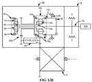
いくつかの実施形態では、CVP/IVPモードと無段可変モードとは、第2のリングアセンブリの回転速度において間隙をもたらす。一実施形態では、間隙は、エンジン速度調節によって補償される。いくつかの実施形態では、CVP/IVPモードにおける第2のリングアセンブリおよび無段可変モードにおける第2のリングアセンブリの回転速度と、エンジンからの入力シャフトの回転速度との関係は、図13に示されるようなものである。いくつかの実施形態では、ギヤボックスが、以前に存在した間隙が、エンジン速度調節を伴わずに、完全に補完され得るように、追加される。ギヤボックスは、可変トランスミッションにおける比(バリエータの比を選択することによって)、係合されるクラッチ、およびギヤボックス比を適切に選択することによって、最大逆進速度から最大前進速度に速度を連続的に変化させることを促進する。そのようなギヤボックスはまた、実施形態の出力の前進最大速度と最大逆進速度との間の速度の広がりを増加させることを可能にし得る。 In some embodiments, the CVP / IVP mode and the continuously variable mode provide a gap in the rotational speed of the second ring assembly. In one embodiment, the gap is compensated by engine speed adjustment. In some embodiments, the relationship between the rotational speed of the second ring assembly in CVP / IVP mode and the second ring assembly in continuously variable mode and the rotational speed of the input shaft from the engine is shown in FIG. It is like that. In some embodiments, a gearbox is added so that the previously existing gap can be fully complemented without engine speed adjustment. Gearbox continuously speeds from maximum reverse speed to maximum forward speed by properly selecting ratio in variable transmission (by selecting variator ratio), engaged clutch, and gearbox ratio To promote change. Such a gearbox may also make it possible to increase the speed spread between the output maximum forward speed and the maximum reverse speed of the embodiment.
本明細書に提供されるのは、エンジンと、本明細書に説明される構成のいずれかまたは本明細書の開示を熟読することによって当業者に明白となる、可変トランスミッションと、車両出力とを備えている、車両駆動系である。いくつかの実施形態では、車両出力は、車輪ディファレンシャルおよび車両の1つ以上の車輪を備えている。いくつかの実施形態では、車両出力は、車輪ディファレンシャルおよび駆動車軸を備えている。いくつかの実施形態では、ダンパは、エンジンと可変トランスミッションとの間に配置される。いくつかの実施形態では、ダンパは、少なくとも1つのねじりばねを備えている。 Provided herein are an engine, a variable transmission, and vehicle output that will be apparent to one of ordinary skill in the art upon reading any of the configurations described herein or the disclosure herein. The vehicle drive system is provided. In some embodiments, the vehicle output comprises a wheel differential and one or more wheels of the vehicle. In some embodiments, the vehicle output comprises a wheel differential and a drive axle. In some embodiments, the damper is disposed between the engine and the variable transmission. In some embodiments, the damper comprises at least one torsion spring.
本明細書に提供されるのは、本明細書に説明される構成のいずれかまたは本明細書の開示を熟読することによって当業者に明白となる、可変トランスミッションを提供することを含む、方法。 Provided herein is a method comprising providing a variable transmission that will be apparent to one of ordinary skill in the art upon reading any of the configurations described herein or the disclosure herein.
本明細書に提供されるのは、本明細書に説明される構成のいずれかまたは本明細書の開示を熟読することによって当業者に明白となる、車両駆動系を提供することを含む、方法である。
本願明細書は、例えば、以下の項目も提供する。
(項目1)
可変トランスミッションであって、
入力シャフトと、
前記入力シャフトと駆動係合される遊星ギヤセットと、
前記遊星ギヤセットの外側リングギヤに機械的に連結されている第1のブレーキと、
バリエータキャリアアセンブリ、第1のリングアセンブリ、および第2のリングアセンブリを備えているバリエータであって、前記バリエータは、前記遊星ギヤセットのリングギヤに機械的に連結されている、バリエータと、
前記遊星ギヤセットの太陽ギヤおよび前記バリエータの第1のリングアセンブリに機械的に連結されている第2のブレーキと
を備え、
前記バリエータの第2のリングアセンブリは、前記可変トランスミッションの出力に駆動係合される、可変トランスミッション。
(項目2)
連続可変モードおよび無段可変モードを備えている、項目1に記載の可変トランスミッション。
(項目3)
前記第1のブレーキが係合され、前記第2のブレーキが係合解除されると、前記遊星ギヤセットの前記リングギヤおよび前記バリエータのキャリアは、固定して保持され、それによって、連続可変モードを係合する、項目1に記載の可変トランスミッション。
(項目4)
前記トランスミッションが連続可変モードにあるとき、動力は、前記遊星ギヤセットの前記太陽ギヤを通して、前記第1のリングアセンブリへと渡る、項目2に記載の可変トランスミッション。
(項目5)
前記第2のブレーキが係合され、前記第1のブレーキが係合解除されると、前記遊星ギヤセットの前記太陽ギヤおよび前記第1のリングアセンブリは、固定して保持され、それによって、無段可変モードを係合する、項目1に記載の可変トランスミッション。
(項目6)
動力は、前記無段可変モードでは、前記遊星ギヤセットのリングギヤを通り、前記バリエータのキャリアへと渡る、項目5に記載の可変トランスミッション。
(項目7)
前記無段可変モードでは、前記バリエータは、逆進機能、静止機能、および低速機能を提供する、項目1に記載の可変トランスミッション。
(項目8)
連続可変モードと無段可変モードとの間の遷移は、同時に、前記第1のブレーキおよび前記第2のブレーキのうちの一方を解放しながら、前記第1のブレーキおよび前記第2のブレーキのうちの他方を適用することによって達成される、項目2に記載の可変トランスミッション。
(項目9)
前記バリエータは、前記連続可変モードおよび無段可変モードの両方において、連続的にそのトルク比を変化させ、性能または燃料消費を最適化する、項目2に記載の可変トランスミッション。
(項目10)
前記バリエータは、前記連続可変モードおよび無段可変モードの両方において、連続的にそのトルク比を変化させ、可変トランスミッションのための理想的比を達成する、項目2に記載の可変トランスミッション。
(項目11)
前記連続可変モードと前記無段可変モードとは、前記第2のリングアセンブリの回転速度において間隙をもたらし、前記間隙は、エンジン速度調節によって補償されることが可能である、項目3に記載の可変トランスミッション。
(項目12)
前記連続可変モードにおける前記第2のリングアセンブリおよび前記無段可変モードにおける前記第2のリングアセンブリの回転速度と、前記エンジンからの前記入力シャフトの回転速度との関係は、図5に示されるようなものである、項目11に記載の可変トランスミッション。
(項目13)
可変トランスミッションであって、
入力シャフトと、
前記入力シャフトと駆動係合されるリングギヤを有する遊星ギヤセットと、
バリエータキャリアアセンブリ、第1のリングアセンブリ、および第2のリングアセンブリを備えているバリエータであって、前記第2のリングアセンブリは、前記可変トランスミッションの出力に駆動係合される、バリエータと、
第1のブレーキおよび前記第1のリングアセンブリに連結される遊星ギヤキャリアと、
第2のブレーキおよびバリエータキャリアに連結される太陽ギヤと
を備えている、可変トランスミッション。
(項目14)
連続可変モードおよび無段可変モードを備えている、項目13に記載の可変トランスミッション。
(項目15)
前記第2のブレーキが係合され、前記第1のブレーキが係合解除されると、前記遊星ギヤセットの太陽ギヤは、前記バリエータのキャリアと固定され、連続可変モードを係合する、項目13に記載の可変トランスミッション。
(項目16)
前記トランスミッションが連続可変モードにあるとき、入力動力は、前記遊星ギヤセットのリングギヤを通して、前記第1のリングアセンブリへと渡る、項目14に記載の可変トランスミッション。
(項目17)
前記第1のブレーキが係合され、前記第2のブレーキが係合解除されると、前記遊星ギヤセットのキャリアおよび入力リングアセンブリは、固定され、無段可変モードを係合する、項目13に記載の可変トランスミッション。
(項目18)
前記無段可変モードでは、前記バリエータは、逆進機能、静止機能、および低速機能を提供する、項目17に記載の可変トランスミッション。
(項目19)
連続可変モードと無段可変モードとの間の遷移は、同時に、前記第1のブレーキおよび前記第2のブレーキのうちの一方を解放しながら、前記第1のブレーキおよび前記第2のブレーキのうちの他方を適用することによって達成される、項目14に記載の可変トランスミッション。
(項目20)
前記バリエータは、前記連続可変モードおよび無段可変モードの両方において、連続的にそのトルク比を変化させ、性能または燃料消費を最適化する、項目14に記載の可変トランスミッション。
(項目21)
前記バリエータは、前記連続可変モードおよび無段可変モードの両方において、連続的にそのトルク比を変化させ、可変トランスミッションのための理想的比を達成する、項目14に記載の可変トランスミッション。
(項目22)
前記連続可変モードと前記無段可変モードとは、前記第2のリングアセンブリの重複回転速度を有する、項目14に記載の可変トランスミッション。
(項目23)
前記無段可変モードの回転速度範囲は、前記連続可変モードにおける前記回転速度より広い、項目22に記載の可変トランスミッション。
(項目24)
前記連続可変モードにおける前記第2のリングアセンブリおよび前記無段可変モードにおける前記第2のリングアセンブリの回転速度と、前記エンジンからの前記入力シャフトの回転速度との関係は、図7に示されるようなものである、項目22に記載の可変トランスミッション。
(項目25)
可変トランスミッションであって、
入力シャフトと、
第1のリングアセンブリ、第2のリングアセンブリ、およびキャリアアセンブリを備えているバリエータであって、前記第2のリングアセンブリは、前記可変トランスミッションの出力に駆動係合される、バリエータと、
前記入力シャフトと駆動係合される太陽ギヤ、前記キャリアアセンブリのバリエータキャリアと駆動係合されるリングギヤ、および遊星キャリア上の1つ以上の遊星ギヤを備えている遊星ギヤセットであって、前記遊星ギヤは、前記太陽ギヤと前記リングギヤとの間に機械的係合で配置されている、遊星ギヤセットトと、
前記リングギヤに連結されている第1のブレーキであって、前記第1のブレーキは、前記第1のブレーキが係合されると、前記リングギヤを固定して保持するように構成されている、第1のブレーキと、
前記遊星キャリアおよび前記第1のリングアセンブリに連結されている第2のブレーキであって、前記第2のブレーキは、前記第2のブレーキが係合されると、前記遊星キャリアを固定して保持するように構成されている、第2のブレーキと
を備えている、可変トランスミッション。
(項目26)
連続可変モードおよび無段可変モードを備えている、項目25に記載の可変トランスミッション。
(項目27)
前記第1のブレーキが係合され、前記第2のブレーキが係合解除されると、連続可変モードを係合するために、前記リングギヤおよび前記バリエータキャリアは固定される、項目25に記載の可変トランスミッション。
(項目28)
前記トランスミッションが前記連続可変モードにあるとき、入力動力は、前記遊星キャリアを通して、前記第1のリングアセンブリへと渡る、項目27に記載の可変トランスミッション。
(項目29)
前記第2のブレーキが係合され、前記第1のブレーキが係合解除されると、無段可変モードを係合するために、前記遊星キャリアおよび前記第1のリングアセンブリは、前記第2のブレーキによって固定して保持される、項目25に記載の可変トランスミッション。
(項目30)
前記トランスミッションが前記無段可変モードにあるとき、動力は、前記遊星ギヤセットのリングギヤを通して、前記バリエータキャリアへと渡る、項目29に記載の可変トランスミッション。
(項目31)
前記無段可変モードでは、前記バリエータは、逆進機能、静止機能、および低速機能を提供する、項目26に記載の可変トランスミッション。
(項目32)
連続可変モードと無段可変モードとの間の遷移は、同時に、前記第1のブレーキおよび前記第2のブレーキのうちの一方を解放しながら、前記第1のブレーキおよび前記第2のブレーキのうちの他方を適用することによって達成される、項目26に記載の可変トランスミッション。
(項目33)
前記バリエータは、前記連続可変モードおよび無段可変モードの両方において、連続的にそのトルク比を変化させ、性能または燃料消費を最適化する、項目26に記載の可変トランスミッション。
(項目34)
前記バリエータは、前記連続可変モードおよび無段可変モードの両方において、連続的にそのトルク比を変化させ、可変トランスミッションのための理想的比を達成する、項目26に記載の可変トランスミッション。
(項目35)
前記連続可変モードと前記無段可変モードとは、前記第2のリングアセンブリの重複回転速度を提供する、項目25に記載の可変トランスミッション。
(項目36)
前記連続可変モードおよび無段可変モードは、前記入力シャフトの回転速度より低い前記第2のリングアセンブリの回転速度を有する、項目25に記載の可変トランスミッション。
(項目37)
前記連続可変モードにおける前記第2のリングアセンブリおよび前記無段可変モードにおける前記第2のリングアセンブリの回転速度と、前記エンジンからの前記入力シャフトの回転速度との関係は、図9に示されるようなものである、項目35に記載の可変トランスミッション。
(項目38)
可変トランスミッションであって、
第1のリングアセンブリ、第2のリングアセンブリ、およびキャリアアセンブリを備えているバリエータであって、前記第2のリングアセンブリは、前記可変トランスミッションの出力に駆動係合される、バリエータと、
前記入力シャフトと駆動係合される太陽ギヤ、前記第1のリングアセンブリと駆動係合されるリングギヤ、および遊星キャリア上の1つ以上の遊星ギヤを備えている遊星ギヤセットであって、前記遊星ギヤは、前記太陽ギヤと前記リングギヤとの間に機械的係合で配置されている、遊星ギヤセットトと、
前記第1のリングアセンブリに連結されている第1のブレーキであって、前記第1のブレーキは、前記第1のブレーキが係合されると、前記遊星ギヤセットのリングギヤおよび前記第1のリングアセンブリを固定して保持するように構成されている、第1のブレーキと、
前記キャリアアセンブリの遊星キャリアおよびバリエータキャリアに連結されている第2のブレーキであって、前記第2のブレーキは、前記第2のブレーキが係合されると、前記遊星キャリアおよび前記バリエータキャリアを固定して保持するように構成されている、第2のブレーキと
を備えている、可変トランスミッション。
(項目39)
連続可変モードおよび無段可変モードを備えている、項目38に記載の可変トランスミッション。
(項目40)
前記第2のブレーキが係合され、前記第1のブレーキが係合解除されると、連続可変モードを係合するために、前記遊星キャリアおよび前記バリエータキャリアは、固定して保持される、項目25に記載の可変トランスミッション。
(項目41)
前記トランスミッションが前記連続可変モードにあるとき、動力は、前記遊星機構リングギヤを通って渡り、前記第1のリングアセンブリに進む、項目40に記載の可変トランスミッション。
(項目42)
前記第1のブレーキが係合され、前記第2のブレーキが係合解除されると、無段可変モードを係合するために、前記リングギヤおよび前記第1のリングアセンブリは、固定して保持される、項目38に記載の可変トランスミッション。
(項目43)
前記トランスミッションが前記無段可変モードにあるとき、動力は、前記遊星キャリアを通して、前記バリエータキャリアへと渡る、項目42に記載の可変トランスミッション。
(項目44)
前記無段可変モードでは、前記バリエータは、逆進機能、静止機能、および低速機能を提供する、項目39に記載の可変トランスミッション。
(項目45)
連続可変モードと無段可変モードとの間の遷移は、同時に、前記第1のブレーキおよび前記第2のブレーキのうちの一方を解放しながら、前記第1のブレーキおよび前記第2のブレーキのうちの他方を適用することによって達成される、項目38に記載の可変トランスミッション。
(項目46)
前記バリエータは、前記連続可変モードおよび無段可変モードの両方において、連続的にそのトルク比を変化させ、性能または燃料消費を最適化する、項目38に記載の可変トランスミッション。
(項目47)
前記バリエータは、前記連続可変モードおよび無段可変モードの両方において、連続的にそのトルク比を変化させ、可変トランスミッションのための理想的比を達成する、項目38に記載の可変トランスミッション。
(項目48)
前記連続可変モードと前記無段可変モードとは、前記第2のリングアセンブリの回転速度において間隙をもたらし、前記間隙は、エンジン速度調節によって補償されることが可能である、項目39に記載の可変トランスミッション。
(項目49)
前記連続可変モードにおける前記第2のリングアセンブリおよび前記無段可変モードにおける前記第2のリングアセンブリの回転速度と、前記エンジンからの前記入力シャフトの回転速度との関係は、図11に示されるようなものである、項目48に記載の可変トランスミッション。
(項目50)
可変トランスミッションであって、
入力シャフトと、
前記入力シャフトに連結されている第1のクラッチ部材と、第2のクラッチ部材とを備えているクラッチと、
その上に形成される前記第2のクラッチ部材を有する第1のリングアセンブリ、前記可変トランスミッションの出力に駆動係合される第2のリングアセンブリ、およびキャリアアセンブリを備えているバリエータと、
前記入力シャフトと駆動係合される太陽ギヤ、前記キャリアアセンブリのバリエータキャリアと駆動係合される遊星キャリア上の1つ以上の遊星ギヤを備え、前記遊星ギヤセットのリングギヤは、固定して保持されている、遊星ギヤセットと、
前記第1のリングアセンブリに連結されている第1のブレーキであって、前記第1のブレーキは、前記第1のブレーキが係合されると、前記第1のリングアセンブリを固定して保持するように構成されている、第1のブレーキと
を備え、
前記第1のリングアセンブリは、前記第1のクラッチ部材が前記第2のクラッチ部材を係合すると、前記入力シャフトと駆動係合される、可変トランスミッション。
(項目51)
組み合わせられた連続可変/無段可変モード(CVP/IVPモード)、または無段可変モードを備えている、項目50に記載の可変トランスミッション。
(項目52)
前記クラッチが係合されると、前記組み合わせられた連続可変/無段可変モード(CVP/IVPモード)に係合するために、前記第1のリングアセンブリおよび前記バリエータキャリアは両方とも、駆動される、項目51に記載の可変トランスミッション。
(項目53)
前記組み合わせられた連続可変/無段可変モードにおける前記可変トランスミッションは、連続可変モードにおいて生成された速度と無段可変モードにおいて生成された速度との間の前記第2のリングアセンブリの回転速度を生成する、項目51に記載の可変トランスミッション。
(項目54)
前記第1のリングアセンブリが、前記ブレーキと固定して保持され、前記クラッチが、係合解除されると、前記無段可変モードが係合される、項目51に記載の可変トランスミッション。
(項目55)
前記動力は、前記無段可変モードでは、前記遊星キャリアを通して、前記バリエータキャリアへと渡る、項目54に記載の可変トランスミッション。
(項目56)
前記バリエータは、前記無段可変モードでは、逆進機能、静止機能、および低速機能を提供する、項目51に記載の可変トランスミッション。
(項目57)
前記連続可変/無段可変モード(CVP/IVPモード)と前記無段可変(IVP)モードとの間の遷移は、前記クラッチを係合解除し、前記ブレーキを係合することによって達成される、項目51に記載の可変トランスミッション。
(項目58)
前記バリエータは、前記連続可変モードおよび無段可変モードの両方において、連続的にそのトルク比を変化させ、性能または燃料消費を最適化する、項目51に記載の可変トランスミッション。
(項目59)
前記バリエータは、前記連続可変モードおよび無段可変モードの両方において、連続的にそのトルク比を変化させ、可変トランスミッションのための理想的比を達成する、項目51に記載の可変トランスミッション。
(項目60)
前記CVP/IVPモードと前記無段可変モードとは、前記第2のリングアセンブリの回転速度において間隙をもたらし、前記間隙は、エンジン速度調節によって補償されることが可能である、項目51に記載の可変トランスミッション。
(項目61)
前記CVP/IVPモードにおける前記第2のリングアセンブリおよび前記無段可変モードにおける前記第2のリングアセンブリの回転速度と、前記エンジンからの前記入力シャフトの回転速度との関係は、図13に示されるようなものである、項目60に記載の可変トランスミッション。
(項目62)
エンジンと、項目1−61のいずれかに記載の可変トランスミッションと、車両出力とを備えている車両駆動系。
(項目63)
前記車両出力は、車輪ディファレンシャルおよび車両の1つ以上の車輪を備えている、項目62に記載の車両駆動系。
(項目64)
前記車両出力は、車輪ディファレンシャルおよび駆動車軸を備えている、項目62に記載の車両駆動系。
(項目65)
ダンパが、前記エンジンと前記可変トランスミッションとの間に配置されている、項目62に記載の車両駆動系。
(項目66)
ダンパが、少なくとも1つのねじりばねを備えている、項目62に記載の車両駆動系。
(項目67)
項目1−61のいずれかに記載の可変トランスミッションを提供することを含む方法。
(項目68)
項目62−66のいずれかに記載の車両駆動系を提供することを含む方法。
(項目69)
トラクション流体潤滑剤をさらに備えている、項目1−61のいずれかに記載の可変トランスミッション。
(項目70)
項目1−61のいずれかに記載の可変トランスミッションを備えている車両。
Provided herein is a method comprising providing a vehicle drive train that will be apparent to one of ordinary skill in the art upon reading any of the configurations described herein or the disclosure herein. It is.
This specification provides the following items, for example.
(Item 1)
A variable transmission,
An input shaft;
A planetary gear set drivingly engaged with the input shaft;
A first brake mechanically coupled to an outer ring gear of the planetary gear set;
A variator comprising a variator carrier assembly, a first ring assembly, and a second ring assembly, wherein the variator is mechanically coupled to a ring gear of the planetary gear set;
A second brake mechanically coupled to a sun gear of the planetary gear set and a first ring assembly of the variator;
With
The variable transmission, wherein the second ring assembly of the variator is drivingly engaged with the output of the variable transmission.
(Item 2)
2. The variable transmission according to
(Item 3)
When the first brake is engaged and the second brake is disengaged, the ring gear of the planetary gear set and the carrier of the variator are held fixed, thereby engaging the continuously variable mode. The variable transmission according to
(Item 4)
Item 3. The variable transmission of
(Item 5)
When the second brake is engaged and the first brake is disengaged, the sun gear and the first ring assembly of the planetary gear set are held fixed, thereby providing a continuously variable The variable transmission of
(Item 6)
Item 6. The variable transmission according to item 5, wherein in the continuously variable mode, power passes through the ring gear of the planetary gear set and passes to the carrier of the variator.
(Item 7)
Item 3. The variable transmission of
(Item 8)
The transition between the continuously variable mode and the continuously variable mode simultaneously involves releasing one of the first brake and the second brake while the first brake and the second brake. Item 3. The variable transmission according to
(Item 9)
3. The variable transmission according to
(Item 10)
Item 3. The variable transmission of
(Item 11)
Item 4. The variable of item 3, wherein the continuously variable mode and the continuously variable mode provide a gap at a rotational speed of the second ring assembly, and the gap can be compensated by engine speed adjustment. transmission.
(Item 12)
The relationship between the rotational speed of the second ring assembly in the continuously variable mode and the rotational speed of the second ring assembly in the continuously variable mode and the rotational speed of the input shaft from the engine is as shown in FIG. Item 12. The variable transmission according to Item 11, wherein
(Item 13)
A variable transmission,
An input shaft;
A planetary gear set having a ring gear drivingly engaged with the input shaft;
A variator comprising a variator carrier assembly, a first ring assembly, and a second ring assembly, wherein the second ring assembly is drivingly engaged with the output of the variable transmission;
A planetary gear carrier coupled to a first brake and the first ring assembly;
A sun gear coupled to the second brake and variator carrier;
Equipped with a variable transmission.
(Item 14)
14. A variable transmission according to item 13, comprising a continuously variable mode and a continuously variable mode.
(Item 15)
Item 13, wherein when the second brake is engaged and the first brake is disengaged, the sun gear of the planetary gear set is fixed to the carrier of the variator and engages a continuously variable mode. The variable transmission described.
(Item 16)
15. The variable transmission of item 14, wherein input power passes through the ring gear of the planetary gear set to the first ring assembly when the transmission is in a continuously variable mode.
(Item 17)
Item 13. The carrier and input ring assembly of the planetary gear set is fixed and engages a continuously variable mode when the first brake is engaged and the second brake is disengaged. Variable transmission.
(Item 18)
(Item 19)
The transition between the continuously variable mode and the continuously variable mode simultaneously involves releasing one of the first brake and the second brake while the first brake and the second brake. 15. A variable transmission according to item 14, which is achieved by applying the other of the above.
(Item 20)
Item 15. The variable transmission of item 14, wherein the variator continuously changes its torque ratio in both the continuously variable mode and the continuously variable mode to optimize performance or fuel consumption.
(Item 21)
Item 15. The variable transmission of item 14, wherein the variator continuously changes its torque ratio in both the continuously variable mode and the continuously variable mode to achieve an ideal ratio for the variable transmission.
(Item 22)
15. The variable transmission of item 14, wherein the continuously variable mode and the continuously variable mode have overlapping rotational speeds of the second ring assembly.
(Item 23)
Item 23. The variable transmission according to
(Item 24)
The relationship between the rotation speed of the second ring assembly in the continuously variable mode and the rotation speed of the second ring assembly in the continuously variable mode and the rotation speed of the input shaft from the engine is as shown in FIG. Item 23. The variable transmission according to
(Item 25)
A variable transmission,
An input shaft;
A variator comprising a first ring assembly, a second ring assembly, and a carrier assembly, wherein the second ring assembly is drivingly engaged with an output of the variable transmission;
A planetary gear set comprising a sun gear drivingly engaged with the input shaft, a ring gear drivingly engaged with a variator carrier of the carrier assembly, and one or more planetary gears on a planet carrier, Is arranged in a mechanical engagement between the sun gear and the ring gear, and a planetary gear set,
A first brake coupled to the ring gear, wherein the first brake is configured to fix and hold the ring gear when the first brake is engaged; 1 brake,
A second brake coupled to the planet carrier and the first ring assembly, wherein the second brake holds the planet carrier fixed when the second brake is engaged; A second brake configured to
Equipped with a variable transmission.
(Item 26)
26. A variable transmission according to
(Item 27)
26. The variable of
(Item 28)
28. The variable transmission of
(Item 29)
When the second brake is engaged and the first brake is disengaged, the planet carrier and the first ring assembly are connected to the second ring to engage a continuously variable mode. 26. The variable transmission of
(Item 30)
30. The variable transmission of item 29, wherein when the transmission is in the continuously variable mode, power passes through the ring gear of the planetary gear set to the variator carrier.
(Item 31)
27. The variable transmission of
(Item 32)
The transition between the continuously variable mode and the continuously variable mode simultaneously involves releasing one of the first brake and the second brake while the first brake and the second brake. 27. Variable transmission according to
(Item 33)
(Item 34)
27. The variable transmission of
(Item 35)
26. The variable transmission of
(Item 36)
26. The variable transmission of
(Item 37)
The relationship between the rotational speed of the second ring assembly in the continuously variable mode and the rotational speed of the second ring assembly in the continuously variable mode and the rotational speed of the input shaft from the engine is as shown in FIG.
(Item 38)
A variable transmission,
A variator comprising a first ring assembly, a second ring assembly, and a carrier assembly, wherein the second ring assembly is drivingly engaged with an output of the variable transmission;
A planetary gear set comprising a sun gear drivingly engaged with the input shaft, a ring gear drivingly engaged with the first ring assembly, and one or more planetary gears on a planet carrier, Is arranged in a mechanical engagement between the sun gear and the ring gear, and a planetary gear set,
A first brake coupled to the first ring assembly, wherein the first brake, when engaged with the first brake, includes a ring gear of the planetary gear set and the first ring assembly; A first brake configured to securely hold
A second brake coupled to the planetary carrier and the variator carrier of the carrier assembly, the second brake fixing the planetary carrier and the variator carrier when the second brake is engaged; And a second brake configured to hold
Equipped with a variable transmission.
(Item 39)
40. The variable transmission of
(Item 40)
When the second brake is engaged and the first brake is disengaged, the planet carrier and the variator carrier are held fixed to engage a continuously variable mode. 25. The variable transmission according to 25.
(Item 41)
41. The variable transmission of
(Item 42)
When the first brake is engaged and the second brake is disengaged, the ring gear and the first ring assembly are fixedly held to engage the continuously variable mode. 39. The variable transmission according to
(Item 43)
43. The variable transmission of
(Item 44)
40. The variable transmission of
(Item 45)
The transition between the continuously variable mode and the continuously variable mode simultaneously involves releasing one of the first brake and the second brake while the first brake and the second brake. 40. The variable transmission of
(Item 46)
39. The variable transmission of
(Item 47)
39. The variable transmission of
(Item 48)
40. The variable of
(Item 49)
The relationship between the rotational speed of the second ring assembly in the continuously variable mode and the rotational speed of the second ring assembly in the continuously variable mode and the rotational speed of the input shaft from the engine is as shown in FIG. Item 49. The variable transmission according to Item 48.
(Item 50)
A variable transmission,
An input shaft;
A clutch comprising a first clutch member coupled to the input shaft, and a second clutch member;
A variator comprising a first ring assembly having the second clutch member formed thereon, a second ring assembly drivingly engaged with the output of the variable transmission, and a carrier assembly;
A sun gear that is drivingly engaged with the input shaft, and one or more planetary gears on a planet carrier that is drivingly engaged with a variator carrier of the carrier assembly, wherein the ring gear of the planetary gear set is fixedly held. A planetary gear set,
A first brake coupled to the first ring assembly, the first brake securing and holding the first ring assembly when the first brake is engaged; Configured with the first brake and
With
The first ring assembly is a variable transmission that is drivingly engaged with the input shaft when the first clutch member engages the second clutch member.
(Item 51)
51. The variable transmission of
(Item 52)
When the clutch is engaged, both the first ring assembly and the variator carrier are driven to engage the combined continuously variable / continuously variable mode (CVP / IVP mode). 52. The variable transmission according to item 51.
(Item 53)
The variable transmission in the combined continuously variable / continuously variable mode generates a rotational speed of the second ring assembly between a speed generated in the continuously variable mode and a speed generated in the continuously variable mode. 52. The variable transmission of item 51.
(Item 54)
52. The variable transmission of item 51, wherein the first ring assembly is fixedly held with the brake and the continuously variable mode is engaged when the clutch is disengaged.
(Item 55)
55. The variable transmission of item 54, wherein the power passes through the planet carrier to the variator carrier in the continuously variable mode.
(Item 56)
52. The variable transmission of item 51, wherein the variator provides a reverse function, a stationary function, and a low speed function in the continuously variable mode.
(Item 57)
The transition between the continuously variable / continuously variable mode (CVP / IVP mode) and the continuously variable (IVP) mode is accomplished by disengaging the clutch and engaging the brake. 52. The variable transmission according to item 51.
(Item 58)
52. The variable transmission of item 51, wherein the variator continuously changes its torque ratio in both the continuously variable mode and the continuously variable mode to optimize performance or fuel consumption.
(Item 59)
52. The variable transmission of item 51, wherein the variator continuously changes its torque ratio in both the continuously variable mode and the continuously variable mode to achieve an ideal ratio for the variable transmission.
(Item 60)
52. The item 51, wherein the CVP / IVP mode and the continuously variable mode provide a gap in a rotational speed of the second ring assembly, and the gap can be compensated by engine speed adjustment. Variable transmission.
(Item 61)
The relationship between the rotational speed of the second ring assembly in the CVP / IVP mode and the rotational speed of the second ring assembly in the continuously variable mode and the rotational speed of the input shaft from the engine is shown in FIG. 61. The variable transmission of
(Item 62)
A vehicle drive system comprising an engine, the variable transmission according to any one of Items 1-61, and a vehicle output.
(Item 63)
63. A vehicle drive system according to item 62, wherein the vehicle output comprises a wheel differential and one or more wheels of the vehicle.
(Item 64)
63. A vehicle drive system according to item 62, wherein the vehicle output comprises a wheel differential and a drive axle.
(Item 65)
63. A vehicle drive system according to item 62, wherein a damper is disposed between the engine and the variable transmission.
(Item 66)
63. A vehicle drive train according to item 62, wherein the damper comprises at least one torsion spring.
(Item 67)
62. A method comprising providing a variable transmission according to any of items 1-61.
(Item 68)
67. A method comprising providing a vehicle drive train according to any of items 62-66.
(Item 69)
The variable transmission of any of items 1-61, further comprising a traction fluid lubricant.
(Item 70)
Item 61. A vehicle comprising the variable transmission according to any one of Items 1-61.
(参照による引用)
本明細書に記載の全ての刊行物、特許、および特許出願は、各個々の刊行物、特許、または特許出願が、具体的かつ個々に、参照することによって組み込まれるように示される場合と同様に参照することによって本明細書に組み込まれる。
(Quoted by reference)
All publications, patents, and patent applications mentioned in this specification are the same as if each individual publication, patent, or patent application was specifically and individually indicated to be incorporated by reference. Are incorporated herein by reference.
本発明の新規特徴は、添付の請求項に詳細に記載される。本発明の特徴および利点のさらなる理解は、例証的実施形態を記載する、本発明の原理が利用される、以下の発明を実施するための形態および付随の図面を参照することによって得られるであろう。
自動および手動トランスミッションに加え、現在、自動車車両上で一般に使用される、連続可変トランスミッションまたはCVTが、開発されている。それらのCVTは、非限定的実施例として、可変プーリを伴うベルト、トロイダル形状、および円錐形状の多くのタイプである。CVTの原理は、エンジンが、車の速度およびドライバのトルク要求(スロットル位置)の関数として、トランスミッション比を無段階に変化させることによって、その最も効率的回転速度で稼働することを可能にするというものである。必要な場合、例えば、加速するとき、CVTはまた、より多くの動力を提供する最適比にシフトすることができる。CVTは、ある離散比からシフトするように係合解除し、次の比に係合することによって、パワートランスミッションの中断を要求する通常のトランスミッションとは反対に、パワートランスミッションにいかなる中断も伴わずに、最小比から最大比に比を変化させることができる。 In addition to automatic and manual transmissions, currently continuously variable transmissions or CVTs commonly used on motor vehicles are being developed. These CVTs are, as non-limiting examples, many types of belts with variable pulleys, toroidal shapes, and conical shapes. The principle of CVT says that the engine can operate at its most efficient rotational speed by steplessly changing the transmission ratio as a function of vehicle speed and driver torque demand (throttle position). Is. If necessary, for example, when accelerating, the CVT can also shift to an optimal ratio that provides more power. The CVT disengages to shift from one discrete ratio and engages the next ratio without any interruption to the power transmission, as opposed to a normal transmission requiring a power transmission interruption. The ratio can be changed from the minimum ratio to the maximum ratio.
CVTの具体的使用は、無段可変トランスミッションまたはIVTである。CVTが、正の速度比に制限される場合、IVT構成は、ギヤをニュートラルにし、比を無段階に逆転させることさえできる。CVTは、いくつかの駆動系構成において、IVTとして使用されることができる。 A specific use of CVT is a continuously variable transmission or IVT. If CVT is limited to a positive speed ratio, the IVT configuration can even make the gear neutral and reverse the ratio steplessly. The CVT can be used as an IVT in some driveline configurations.
本明細書に提供されるのは、連続可変遊星機構のための、CVPとしても知られる、ボール式CVTに基づく、構成である。CVTの側面は、参照することによってその全体として本明細書に組み込まれる、第US60/616,399号または第AU2011224083A1号に説明されている。本明細書で使用されるCVTのタイプは、用途に応じて、複数のバリエータボールと、各々がバリエータボールを係合する係合部分を有する2つのディスクまたは環状リングとから成る。係合部分は、入力および出力として、バリエータボールと接触する、円錐形あるいはトロイダル凸状または凹状表面であり得る。CVTは、図1に示されるように、同様に、ボールに接触するアイドラを含み得る。バリエータボールは、軸上に搭載され、それ自体が、バリエータボールの車軸を傾斜させることによって、比を変化させることを可能にする、ケージまたはキャリア内に保持される。Milnerによって生産されるもののような、他のタイプのボールCVTもまた、存在するが、若干、異なる。これらの代替ボールCVTも、加えて、本明細書で検討される。概して、ボール式CVTの作業原理は、図2に示される。
Provided herein is a configuration based on a ball CVT, also known as CVP, for a continuously variable planetary mechanism. Aspects of CVT are described in
CVP自体は、トラクション流体と協働する。ボールと円錐形リングとの間の潤滑剤は、高圧力では、固体として作用し、第1のリングアセンブリから、バリエータボールを通して、第2のリングアセンブリに動力を伝達する。バリエータボールの軸を傾斜させることによって、比は、入力と出力との間で変化させられることができる。バリエータボールのそれぞれの軸が、水平であるとき、比は、1であり、軸が傾斜させられると、軸と接点との間の距離が変化し、全体的比を修正する。バリエータボールの車軸は全て、ケージ内に含まれる機構と同時に傾斜させられる。 The CVP itself cooperates with the traction fluid. The lubricant between the ball and the conical ring acts as a solid at high pressure and transmits power from the first ring assembly through the variator ball to the second ring assembly. By tilting the variator ball axis, the ratio can be varied between input and output. When each axis of the variator ball is horizontal, the ratio is 1, and when the axis is tilted, the distance between the axis and the contact changes, modifying the overall ratio. All variator ball axles are tilted simultaneously with the mechanism contained within the cage.
車では、CVTは、従来のトランスミッションに取って代わるために使用され、図3に示されるように、エンジン(ICEまたは内燃エンジン)とディファレンシャルとの間に位置する。ねじりダンパ(代替として、ダンパと呼ばれる)が、エンジンとCVTとの間に導入され、CVTに損傷を及ぼし得る伝達トルクピークおよび振動を回避し得る。いくつかの構成では、このダンパは、始動機能のためのクラッチと連結されることができる。 In a car, the CVT is used to replace a conventional transmission and is located between the engine (ICE or internal combustion engine) and the differential, as shown in FIG. Torsional dampers (alternatively called dampers) can be introduced between the engine and the CVT to avoid transmission torque peaks and vibrations that can damage the CVT. In some configurations, the damper can be coupled with a clutch for a start function.
実施形態トランスミッション(および、結果として生じる駆動系)は、図4A、4B、6、8、10、および12A、12Bに示される。これらの構成の中心部品は、バリエータ10a(要素10b−eとしても描写される)等のバリエータである。そのようなバリエータは、典型的には、前述の傾斜ボール式CVPを備え得る。そのようなバリエータ10a−10eは、典型的には、各々が、第1のリングアセンブリと、第2のリングアセンブリと、その間に配置されるキャリアアセンブリとを備えている。ここで図4aを参照すると、バリエータ10aは、第1のリングアセンブリ12Aと、第2のリングアセンブリ11aと、キャリアアセンブリ13a(「バリエータキャリアアセンブリ」または「バリエータキャリア」とも称される)とを備えているように示される。キャリアアセンブリは、典型的には、本明細書に説明されるように、傾斜可能車軸シャフトを有する複数のバリエータボールを含む。いくつかの実施形態では、第1のリングアセンブリは、筐体内に回転可能に配置される。第1のリングアセンブリは、キャリアアセンブリの複数のバリエータボールと駆動係合する第1のバリエータボール係合表面を備えている。いくつかの実施形態では、第1のリングアセンブリは、入力シャフトと駆動係合され得る。
Embodiment transmissions (and resulting drive trains) are shown in FIGS. 4A, 4B, 6, 8, 10, and 12A, 12B. The central part of these configurations is a variator such as
第1のバリエータボール係合表面は、第1のリングアセンブリの遠位端に形成される。本明細書に意味されるように、バリエータのリングアセンブリを説明するとき、遠位は、バリエータボールに最も近いリングアセンブリの部分を意味する。いくつかの実施形態では、第1のバリエータボール係合表面は、バリエータボールの各々と接触する、またはそこから若干離間されている円錐形表面、凹状トロイダル表面、または凸状トロイダル表面である。いくつかの実施形態では、第1のバリエータボール係合表面は、境界層式摩擦および弾性流体力学膜のうちの1つを通して、キャリアアセンブリのバリエータボールの各々と駆動係合する。 A first variator ball engaging surface is formed at the distal end of the first ring assembly. As meant herein, when describing a variator ring assembly, distal means the portion of the ring assembly that is closest to the variator ball. In some embodiments, the first variator ball engaging surface is a conical surface, concave toroidal surface, or convex toroidal surface that contacts or is slightly spaced from each of the variator balls. In some embodiments, the first variator ball engaging surface is drivingly engaged with each of the variator balls of the carrier assembly through one of boundary layer friction and elastohydrodynamic membranes.
図4A、4B、6、8、10、および12A、12Bに示されるいくつかの実施形態のバリエータキャリアアセンブリ(13a−e)は、筐体内に回転可能に配置され、第1のリングアセンブリと駆動係合され得る。いくつかの実施形態では、キャリアアセンブリは、各々が傾斜可能ボール車軸シャフトを有する複数の傾斜可能バリエータボールの環状配列を備え得る。キャリアアセンブリのケージは、グラウンドに結合されるグラウンディングデバイスによって、筐体に対して回転することを防止されるように構成され得る。いくつかの実施形態では、ボール車軸シャフトの各々は、カム式傾斜機構を使用して調節される。いくつかの実施形態では、ボール車軸シャフトの各々は、分割キャリア車軸傾斜機構を使用して調節される。 The variator carrier assemblies (13a-e) of some embodiments shown in FIGS. 4A, 4B, 6, 8, 10, and 12A, 12B are rotatably disposed within the housing and drive with the first ring assembly. Can be engaged. In some embodiments, the carrier assembly may comprise an annular array of a plurality of tiltable variator balls, each having a tiltable ball axle shaft. The cage of the carrier assembly may be configured to be prevented from rotating relative to the housing by a grounding device coupled to ground. In some embodiments, each of the ball axle shafts is adjusted using a cam tilt mechanism. In some embodiments, each of the ball axle shafts is adjusted using a split carrier axle tilt mechanism.
図4A、4B、6、8、10、および12A、12Bに描写されるように、少なくとも、第2のリングアセンブリは、筐体内に回転可能に配置される。第2のリングアセンブリは、キャリアアセンブリのバリエータボールと駆動係合する第2のバリエータボール係合表面を備えている。いくつかの実施形態では、第2のバリエータボール係合表面は、第2のリングアセンブリの遠位端に形成される。いくつかの実施形態では、第2のバリエータボール係合表面は、バリエータボールの各々と接触するか、またはそこから若干離間されている円錐形表面、凹状トロイダル表面、または凸状トロイダル表面である。いくつかの実施形態では、第2のバリエータボール係合表面は、境界層式摩擦および弾性流体力学膜のうちの1つを通して、キャリアアセンブリのバリエータボールの各々と駆動係合する。 As depicted in FIGS. 4A, 4B, 6, 8, 10, and 12A, 12B, at least the second ring assembly is rotatably disposed within the housing. The second ring assembly includes a second variator ball engagement surface that is drivingly engaged with the variator ball of the carrier assembly. In some embodiments, the second variator ball engaging surface is formed at the distal end of the second ring assembly. In some embodiments, the second variator ball engagement surface is a conical surface, a concave toroidal surface, or a convex toroidal surface that contacts or is slightly spaced from each of the variator balls. In some embodiments, the second variator ball engaging surface is drivingly engaged with each of the variator balls of the carrier assembly through one of boundary layer friction and elastohydrodynamic membranes.
バリエータの両側のボールランプ(要素15a−eとして描写される)は、トルクを伝達するために必要なクランプ力を提供する。第1のリングアセンブリ上の第1のスラストリングおよび第2のリングアセンブリ上の第2のスラストリングを構成するボールランプ(一対の垂直線間の円形によって、図4A、4B、6、8、10、および12A、12Bに示される)は、示されるように、可変トランスミッションの構成要素間に配置され、可変トランスミッションの適切な動作(すなわち、トルクの伝達)のために必要な軸方向力の量を生成する。しかしながら、適切な動作のために必要な軸方向力の量は、クランプ機構(図示せず)によって、または可変トランスミッションの組立の間に与えられる負荷として生成され得ることを理解されたい。したがって、図4A、4B、6、8、10、および12A、12Bに描写されるように、バリエータの両側のボールランプは、本実施形態では、トルクを伝達するために必要なクランプ力を提供する。
Ball ramps on both sides of the variator (depicted as
本明細書に提供されるのは、動力入力シャフトと、動力入力シャフトに機械的に連結される遊星ギヤセットと、バリエータキャリアアセンブリ、第1のリングアセンブリ、および第2のリングアセンブリを備えているバリエータと、ブレーキおよびクラッチの種々の組み合わせとを備えている可変トランスミッションである。 Provided herein is a variator comprising a power input shaft, a planetary gear set mechanically coupled to the power input shaft, a variator carrier assembly, a first ring assembly, and a second ring assembly. And variable combinations of brakes and clutches.
いくつかの実施形態では、可変トランスミッションは、連続可変モード、無段可変モード、またはそれらの組み合わせを有するバリエータを備えている。 In some embodiments, the variable transmission includes a variator having a continuously variable mode, a continuously variable mode, or a combination thereof.
いくつかの実施形態では、可変トランスミッションは、逆進機能、静止機能、および低速機能を提供することができる。 In some embodiments, the variable transmission can provide a reverse function, a stationary function, and a low speed function.
いくつかの実施形態では、連続可変トランスミッションモードと無段可変トランスミッションモードとの間の遷移は、同時に、ブレーキの一方を解放し、他方のブレーキを適用することによって達成される。 In some embodiments, the transition between the continuously variable transmission mode and the continuously variable transmission mode is accomplished by simultaneously releasing one of the brakes and applying the other brake.
いくつかの実施形態では、連続可変トランスミッションモードと無段可変トランスミッションモードとの間の遷移は、クラッチを解放し、ブレーキを係合することによって達成される。 In some embodiments, the transition between continuously variable transmission mode and continuously variable transmission mode is achieved by disengaging the clutch and engaging the brake.
いくつかの実施形態では、バリエータは、連続可変モードおよび無段可変モードの両方において、そのトルク比を連続的に変化させ、エンジンのために達成可能な最良比を提供し、性能または燃料消費を最適化することが可能である。 In some embodiments, the variator continuously changes its torque ratio in both continuously variable and continuously variable modes, providing the best ratio achievable for the engine, and improving performance or fuel consumption. It is possible to optimize.
本明細書に提供されるのは、可変トランスミッション(VT)であって、入力シャフトと、その遊星キャリアを通して入力シャフトと駆動係合される遊星ギヤセットと、遊星ギヤセットのリングギヤに機械的に連結されている第1のブレーキと、バリエータキャリアアセンブリ、第1のリングアセンブリ、および第2のリングアセンブリを備えているバリエータであって、バリエータのキャリアは、遊星ギヤセットのリングギヤに機械的に連結される、バリエータと、遊星ギヤセットの太陽ギヤおよび第1のリングアセンブリに機械的に連結されている第2のブレーキとを備え、第2のリングアセンブリは、VTの出力と駆動係合される可変トランスミッションである。そのような可変トランスミッションは、図4Aの実施形態に描写される。 Provided herein is a variable transmission (VT), mechanically coupled to an input shaft, a planetary gear set drivingly engaged with the input shaft through its planet carrier, and a ring gear of the planetary gear set. A variator comprising a first brake and a variator carrier assembly, a first ring assembly, and a second ring assembly, wherein the variator carrier is mechanically coupled to the ring gear of the planetary gear set. And a sun gear of the planetary gear set and a second brake mechanically coupled to the first ring assembly, the second ring assembly being a variable transmission that is drivingly engaged with the output of the VT. Such a variable transmission is depicted in the embodiment of FIG. 4A.
図4Aは、入力シャフト1と、その遊星キャリア8aを通して、入力シャフトと駆動係合される遊星ギヤセット5aと、遊星ギヤセットのリングギヤ9a機械的に連結される第1のブレーキ16と、バリエータキャリアアセンブリ13a、一式の傾斜ボール14a、第1のリングアセンブリ12a、および第2のリングアセンブリ11aを備えているバリエータ10a(本願のいずれかに説明されるように)であって、バリエータキャリアアセンブリは、遊星ギヤセット5aのリングギヤ9aに機械的に連結される、バリエータと、遊星ギヤセットの太陽ギヤ6aおよび第1のリングアセンブリ12aに機械的に連結され得る、第2のブレーキ17とを備えている、本発明の特定の実施形態のVTを描写する。第2のリングアセンブリ11aは、VTの出力と駆動係合される。
FIG. 4A shows an
いくつかの実施形態では、可変トランスミッションは、連続可変モードおよび無段可変モードを備えている。いくつかの実施形態では、第1のブレーキが係合され、第2のブレーキが係合解除されると、遊星ギヤセットのリングギヤおよびバリエータキャリアアセンブリ(「バリエータキャリア」または「バリエータのキャリア」とも称される)は、固定して保持され、それによって、連続可変モードを係合する。いくつかの実施形態では、トランスミッションが連続可変モードにあるとき、動力は、遊星ギヤセットの太陽ギヤを通して、第1のリングアセンブリへと渡り得る。例えば、図4Aの実施形態では、第1のブレーキが係合され、第2のブレーキが係合解除されると、遊星ギヤセット50aのリングギヤ9aおよびバリエータキャリアアセンブリ13aは、固定して保持され、それによって、連続可変モードを係合する。
In some embodiments, the variable transmission has a continuously variable mode and a continuously variable mode. In some embodiments, when the first brake is engaged and the second brake is disengaged, the ring gear and variator carrier assembly (also referred to as “variator carrier” or “variator carrier”) of the planetary gear set. Are held fixed, thereby engaging the continuously variable mode. In some embodiments, power can pass through the sun gear of the planetary gear set to the first ring assembly when the transmission is in a continuously variable mode. For example, in the embodiment of FIG. 4A, when the first brake is engaged and the second brake is disengaged, the
いくつかの実施形態では第2のブレーキが係合され、第1のブレーキが係合解除されると、遊星ギヤセットの太陽ギヤおよび第1のリングアセンブリは、固定して保持され、それによって、無段可変モードを係合する。いくつかの実施形態では、動力は、無段可変モードでは、遊星ギヤセットのリングギヤを通して、バリエータのキャリアへと渡る。いくつかの実施形態では、無段可変モードでは、バリエータは、逆進機能、静止機能、および低速機能を提供する。例えば、図4Aの実施形態では、第2のブレーキが係合され、第1のブレーキが係合解除されると、遊星ギヤセット5aの太陽ギヤ6aおよび第1のリングアセンブリは、固定して保持され、それによって、無段可変モードを係合する。そのようなモードでは、動力は、遊星ギヤセット5aのリングギヤ9aを通して、バリエータキャリアアセンブリ13aへと渡り得る。
In some embodiments, when the second brake is engaged and the first brake is disengaged, the sun gear and the first ring assembly of the planetary gear set are held securely, thereby Engage stage variable mode. In some embodiments, power passes through the ring gear of the planetary gear set to the variator carrier in the continuously variable mode. In some embodiments, in the continuously variable mode, the variator provides a reverse function, a stationary function, and a low speed function. For example, in the embodiment of FIG. 4A, when the second brake is engaged and the first brake is disengaged, the
いくつかの実施形態では、連続可変モードと無段可変モードとの間の遷移は、同時に、第1のブレーキおよび第2のブレーキのうちの一方を解放しながら、第1のブレーキおよび第2のブレーキのうちの他方を適用することによって達成される。いくつかの実施形態では、バリエータは、連続可変モードおよび無段可変モードの両方において、連続的にそのトルク比を変化させ、性能または燃料消費を最適化する。いくつかの実施形態では、バリエータは、連続可変モードおよび無段可変モードの両方において、連続的にそのトルク比を変化させ、可変トランスミッションのための理想的比を達成する。 In some embodiments, the transition between continuously variable mode and continuously variable mode simultaneously releases the first brake and the second brake while releasing one of the first brake and the second brake. This is accomplished by applying the other of the brakes. In some embodiments, the variator continuously changes its torque ratio in both continuously variable and continuously variable modes to optimize performance or fuel consumption. In some embodiments, the variator continuously changes its torque ratio in both continuously variable and continuously variable modes to achieve an ideal ratio for a variable transmission.
いくつかの実施形態では、連続可変モードと無段可変モードとは、第2のリングアセンブリの回転速度において間隙をもたらす。一実施形態では、間隙は、エンジン速度調節によって補償される。いくつかの実施形態では、連続可変モードにおける第2のリングアセンブリの回転速度および無段可変モードにおける第2のリングアセンブリの回転速度と、エンジンからの入力シャフトの回転速度との関係は、図5に示されるようなものである。 In some embodiments, the continuously variable mode and the continuously variable mode provide a gap at the rotational speed of the second ring assembly. In one embodiment, the gap is compensated by engine speed adjustment. In some embodiments, the relationship between the rotational speed of the second ring assembly in the continuously variable mode and the rotational speed of the second ring assembly in the continuously variable mode and the rotational speed of the input shaft from the engine is shown in FIG. As shown in
いくつかの実施形態では、ギヤボックスが、以前に存在した間隙が、エンジン速度調節を伴わずに、完全に補完され得るように、追加される。図4Bは、ギヤボックス18が、CVTとディファレンシャル4との間に追加された図4Aの実施形態を示す。いくつかの実施形態では、ギヤボックスは、(バリエータにおける)CVTにおける比、係合されるクラッチ、およびギヤボックス比を適切に選択することによって、最大逆進速度から最大前進速度に速度を連続的に変動させることを可能にする。そのようなギヤボックスはまた、実施形態のCVTトランスミッション出力の最大逆進速度と最大前進速度との間の広がりを増加させることを可能にし得る。
In some embodiments, a gearbox is added so that the previously existing gap can be fully complemented without engine speed adjustment. FIG. 4B shows the embodiment of FIG. 4A in which a
本明細書に提供されるのは、可変トランスミッションであって、入力シャフトと、入力シャフトと駆動係合される遊星ギヤセットのリングギヤと、バリエータキャリアアセンブリ、第1のリングアセンブリ、および第2のリングアセンブリを備えているバリエータと、第1のブレーキおよび第1のリングアセンブリに連結される遊星ギヤキャリアと、第2のブレーキおよびバリエータキャリアに連結される太陽ギヤと、VTの出力に駆動係合されるバリエータの第2のリングアセンブリとを備えている、可変トランスミッションである。 Provided herein is a variable transmission comprising an input shaft, a ring gear of a planetary gear set that is drivingly engaged with the input shaft, a variator carrier assembly, a first ring assembly, and a second ring assembly. A planetary gear carrier coupled to the first brake and the first ring assembly, a sun gear coupled to the second brake and the variator carrier, and drivingly engaged to the output of the VT A variable transmission comprising a second ring assembly of the variator.
いくつかの実施形態では、可変トランスミッションは、連続可変モードおよび無段可変モードを備えている。いくつかの実施形態では、第2のブレーキが係合され、第1のブレーキが係合解除されると、遊星ギヤセットの太陽ギヤは、バリエータキャリアアセンブリとともに固定され、連続可変モードを係合する。そのような実施形態の実施例は、図6に描写され、以下に論じられる。 In some embodiments, the variable transmission has a continuously variable mode and a continuously variable mode. In some embodiments, when the second brake is engaged and the first brake is disengaged, the sun gear of the planetary gear set is secured with the variator carrier assembly and engages the continuously variable mode. An example of such an embodiment is depicted in FIG. 6 and discussed below.
いくつかの実施形態では、第1のブレーキが係合され、第2のブレーキが係合解除されると、バリエータの入力リングアセンブリ(典型的には、第1のリングアセンブリ)および遊星ギヤキャリア(「遊星キャリア」または「遊星キャリアアセンブリ」とも称される)は、固定され、それによって、無段可変モードを係合する。いくつかの実施形態では、無段可変モードでは、バリエータは、逆進機能、静止機能、および低速機能(前進速度)を提供する。そのような実施形態の実施例は、図6に描写される。 In some embodiments, when the first brake is engaged and the second brake is disengaged, the variator input ring assembly (typically the first ring assembly) and the planetary gear carrier ( The “planet carrier” or “planet carrier assembly”) is fixed, thereby engaging the continuously variable mode. In some embodiments, in the continuously variable mode, the variator provides a reverse function, a stationary function, and a low speed function (forward speed). An example of such an embodiment is depicted in FIG.
その実施例が図6に描写される、いくつかの実施形態では、連続可変モードと無段可変モードとの間の遷移は、同時に、第1のブレーキおよび第2のブレーキのうちの一方を解放しながら、第1のブレーキおよび第2のブレーキのうちの他方を適用することによって達成される。 In some embodiments, examples of which are depicted in FIG. 6, the transition between continuously variable mode and continuously variable mode simultaneously releases one of the first brake and the second brake. However, this is achieved by applying the other of the first brake and the second brake.
そのような実施形態では、バリエータは、連続可変モードおよび無段可変モードの両方において、連続的にそのトルク比を変化させ、性能または燃料消費を最適化する。いくつかの実施形態では、バリエータは、連続可変モードおよび無段可変モードの両方において、連続的にそのトルク比を変化させ、可変トランスミッションのための理想的比を達成する。 In such an embodiment, the variator continuously changes its torque ratio in both continuously variable and continuously variable modes to optimize performance or fuel consumption. In some embodiments, the variator continuously changes its torque ratio in both continuously variable and continuously variable modes to achieve an ideal ratio for a variable transmission.
いくつかの実施形態では、連続可変モードおよび無段可変モードは、重複回転出力速度を有する。例えば、図6に描写される実施形態では、連続可変モードと無段可変モードとは、第2のリングアセンブリの重複回転速度を有し得る。いくつかの実施形態では、無段可変モードの回転速度範囲は、連続可変モードにおける回転速度より広くあり得る。図7は、連続可変モードにおける第2のリングアセンブリの回転速度と無段可変モードにおける第2のリングアセンブリの回転速度との間の例示的関係を示す。 In some embodiments, the continuously variable mode and the continuously variable mode have overlapping rotational output speeds. For example, in the embodiment depicted in FIG. 6, the continuously variable mode and the continuously variable mode may have overlapping rotational speeds of the second ring assembly. In some embodiments, the rotational speed range of the continuously variable mode may be wider than the rotational speed in the continuously variable mode. FIG. 7 shows an exemplary relationship between the rotational speed of the second ring assembly in the continuously variable mode and the rotational speed of the second ring assembly in the continuously variable mode.
本明細書に提供されるのは、可変トランスミッションであって、入力シャフトと、第1のリングアセンブリ、第2のリングアセンブリ、およびキャリアアセンブリを備えているバリエータ(「バリエータキャリアアセンブリ」とも称される)であって、第2のリングアセンブリは、VTの出力と駆動係合されるバリエータと、入力シャフトと駆動係合される太陽ギヤ、バリエータキャリアアセンブリと駆動係合されるリングギヤ、および遊星キャリア上の1つ以上の遊星ギヤ(「遊星キャリアアセンブリ」とも称される)を備えている遊星ギヤセットであって、遊星ギヤは、太陽ギヤとリングギヤとの間に機械的係合で配置されている、遊星ギヤセットトと、リングギヤに連結される第1のブレーキであって、第1のブレーキは、第1のブレーキが係合されると、リングギヤを固定して保持するように構成される第1のブレーキと、遊星キャリアおよび第1のリングアセンブリに連結されている第2のブレーキであって、第2のブレーキは、第2のブレーキが係合されると、遊星キャリアおよび第1のリングアセンブリを固定して保持するように構成されている、第2のブレーキとを備えている可変トランスミッションである。そのような実施形態の実施例は、図8に描写される。 Provided herein is a variable transmission comprising an input shaft, a first ring assembly, a second ring assembly, and a carrier assembly (also referred to as a “variator carrier assembly”). And a second ring assembly on a variator drivingly engaged with the output of the VT, a sun gear drivingly engaged with the input shaft, a ring gear drivingly engaged with the variator carrier assembly, and the planet carrier A planetary gear set comprising one or more planetary gears (also referred to as “planet carrier assembly”), wherein the planetary gears are disposed in mechanical engagement between the sun gear and the ring gear; A planetary gear set and a first brake coupled to the ring gear, wherein the first brake is a first brake. A first brake configured to hold the ring gear fixedly when engaged, and a second brake coupled to the planet carrier and the first ring assembly, The brake is a variable transmission that includes a second brake configured to securely hold the planet carrier and the first ring assembly when the second brake is engaged. An example of such an embodiment is depicted in FIG.
いくつかの実施形態では、可変トランスミッションは、連続可変モードおよび無段可変モードを備えている。 In some embodiments, the variable transmission has a continuously variable mode and a continuously variable mode.
いくつかの実施形態では、第1のブレーキが係合され、第2のブレーキが係合解除されると、リングギヤおよびバリエータキャリアアセンブリは両方とも、固定され、連続可変モードを係合する。いくつかの実施形態では、トランスミッションが連続可変モードにあるとき、入力動力は、遊星キャリアを通して、第1のリングアセンブリへと渡る。 In some embodiments, when the first brake is engaged and the second brake is disengaged, both the ring gear and the variator carrier assembly are fixed and engage the continuously variable mode. In some embodiments, input power passes through the planet carrier to the first ring assembly when the transmission is in a continuously variable mode.
いくつかの実施形態では、第2のブレーキが係合され、第1のブレーキが係合解除されると、遊星キャリアおよび第1のリングアセンブリは、第2のブレーキによって、固定して保持され、無段可変モードを係合する。いくつかの実施形態では、トランスミッションが無段可変モードにあるとき、動力は、遊星ギヤセットのリングを通して、バリエータキャリアへと渡る。いくつかの実施形態では、無段可変モードでは、バリエータは、逆進機能、静止機能、および低速機能を提供する。 In some embodiments, when the second brake is engaged and the first brake is disengaged, the planet carrier and the first ring assembly are held securely by the second brake, Engage continuously variable mode. In some embodiments, when the transmission is in a continuously variable mode, power passes through the ring of the planetary gear set to the variator carrier. In some embodiments, in the continuously variable mode, the variator provides a reverse function, a stationary function, and a low speed function.
いくつかの実施形態では、連続可変モードと無段可変モードとの間の遷移は、同時に、第1のブレーキおよび第2のブレーキのうちの一方を解放しながら、第1のブレーキおよび第2のブレーキのうちの他方を適用することによって達成される。 In some embodiments, the transition between continuously variable mode and continuously variable mode simultaneously releases the first brake and the second brake while releasing one of the first brake and the second brake. This is accomplished by applying the other of the brakes.
いくつかの実施形態では、バリエータは、連続可変モードおよび無段可変モードの両方において、連続的にそのトルク比を変化させ、性能または燃料消費を最適化する。いくつかの実施形態では、バリエータは、連続可変モードおよび無段可変モードの両方において、連続的にそのトルク比を変化させ、可変トランスミッションのための理想的比を達成する。 In some embodiments, the variator continuously changes its torque ratio in both continuously variable and continuously variable modes to optimize performance or fuel consumption. In some embodiments, the variator continuously changes its torque ratio in both continuously variable and continuously variable modes to achieve an ideal ratio for a variable transmission.
いくつかの実施形態では、連続可変モードと無段可変モードとは、第2のリングアセンブリの重複回転速度を提供する。いくつかの実施形態では、連続可変モードおよび無段可変モードは、入力シャフトの回転速度より低い第2のリングアセンブリの回転速度を有する。いくつかの実施形態では、連続可変モードにおける第2のリングアセンブリの回転速度および無段可変モードにおける第2のリングアセンブリの回転速度と、エンジンからの入力シャフトの回転速度との関係は、図9に示されるようなものである。 In some embodiments, the continuously variable mode and the continuously variable mode provide overlapping rotational speeds of the second ring assembly. In some embodiments, the continuously variable mode and the continuously variable mode have a second ring assembly rotational speed that is lower than the rotational speed of the input shaft. In some embodiments, the relationship between the rotational speed of the second ring assembly in the continuously variable mode and the rotational speed of the second ring assembly in the continuously variable mode and the rotational speed of the input shaft from the engine is shown in FIG. As shown in
本明細書に提供されるのは、可変トランスミッションであって、第1のリングアセンブリ、VTの出力に駆動係合される第2のリングアセンブリ、およびキャリアアセンブリを備えているバリエータと、入力シャフトと駆動係合される太陽ギヤ、第1のリングアセンブリと駆動係合されるリングギヤ、および遊星キャリア上の1つ以上の遊星ギヤを備えている遊星ギヤセットであって、遊星ギヤは、太陽ギヤとリングギヤとの間に機械的係合で配置されている、遊星ギヤセットトと、第1のリングアセンブリに連結される第1のブレーキであって、第1のブレーキは、第1のブレーキが係合されると、遊星ギヤセットのリングギヤおよび第1のリングアセンブリを固定して保持するように構成されている、第1のブレーキと、キャリアアセンブリの遊星キャリアおよびバリエータキャリアに連結されている第2のブレーキであって、第2のブレーキは、第2のブレーキが係合されると、遊星キャリアおよびバリエータキャリアを固定して保持するように構成されている、第2のブレーキとを備えている、可変トランスミッションである。 Provided herein is a variable transmission, a variator comprising a first ring assembly, a second ring assembly drivingly engaged with the output of a VT, and a carrier assembly; and an input shaft; A planetary gear set comprising a sun gear that is drivingly engaged, a ring gear that is drivingly engaged with a first ring assembly, and one or more planetary gears on a planet carrier, wherein the planetary gear is a sun gear and a ring gear. A planetary gear set disposed in mechanical engagement between the first ring assembly and a first brake coupled to the first ring assembly, wherein the first brake is engaged with the first brake. A first brake configured to fix and hold the ring gear of the planetary gear set and the first ring assembly; and a carrier assembly A second brake coupled to the planetary carrier and the variator carrier, wherein the second brake fixes and holds the planet carrier and the variator carrier when the second brake is engaged. A variable transmission comprising a second brake configured.
いくつかの実施形態では、可変トランスミッションは、連続可変モードおよび無段可変モードを備えている。 In some embodiments, the variable transmission has a continuously variable mode and a continuously variable mode.
いくつかの実施形態では、第2のブレーキが係合され、第1のブレーキが係合解除されると、遊星キャリアアセンブリおよびバリエータキャリアは、連続可変モードを係合するように固定して保持される。いくつかの実施形態では、トランスミッションが連続可変モードにあるとき、動力は、遊星機構リングギヤを通って渡り、第1のリングアセンブリに及ぶ。 In some embodiments, when the second brake is engaged and the first brake is disengaged, the planet carrier assembly and the variator carrier are held securely to engage the continuously variable mode. The In some embodiments, when the transmission is in a continuously variable mode, power passes through the planetary ring gear and reaches the first ring assembly.
いくつかの実施形態では、第1のブレーキが係合され、第2のブレーキが係合解除されると、リングギヤおよび第1のリングアセンブリは、無段可変モードを係合するように固定して保持される。いくつかの実施形態では、トランスミッションが無段可変モードにあるとき、動力は、遊星キャリアアセンブリを通して、バリエータキャリアアセンブリへと渡る。 In some embodiments, when the first brake is engaged and the second brake is disengaged, the ring gear and the first ring assembly are fixed to engage the continuously variable mode. Retained. In some embodiments, power passes through the planet carrier assembly to the variator carrier assembly when the transmission is in a continuously variable mode.
いくつかの実施形態では、無段可変モードでは、バリエータは、逆進機能、静止機能、および低速機能を提供する。いくつかの実施形態では、連続可変モードと無段可変モードとの間の遷移は、同時に、第1のブレーキおよび第2のブレーキのうちの一方を解放しながら、第1のブレーキおよび第2のブレーキのうちの他方を適用することによって達成される。 In some embodiments, in the continuously variable mode, the variator provides a reverse function, a stationary function, and a low speed function. In some embodiments, the transition between continuously variable mode and continuously variable mode simultaneously releases the first brake and the second brake while releasing one of the first brake and the second brake. This is accomplished by applying the other of the brakes.
いくつかの実施形態では、バリエータは、連続可変モードおよび無段可変モードの両方において、連続的にそのトルク比を変化させ、性能または燃料消費を最適化する。いくつかの実施形態では、バリエータは、連続可変モードおよび無段可変モードの両方において、連続的にそのトルク比を変化させ、VTのための理想的比を達成する。 In some embodiments, the variator continuously changes its torque ratio in both continuously variable and continuously variable modes to optimize performance or fuel consumption. In some embodiments, the variator continuously changes its torque ratio in both continuously variable and continuously variable modes to achieve the ideal ratio for VT.
いくつかの実施形態では、連続可変モードと無段可変モードとは、第2のリングアセンブリの回転速度において間隙をもたらす。一実施形態では、間隙は、エンジン速度調節によって補償される。いくつかの実施形態では、連続可変モードにおける第2のリングアセンブリの回転速度および無段可変モードにおける第2のリングアセンブリの回転速度と、エンジンからの入力シャフトの回転速度との関係は、図11に示されるようなものである。 In some embodiments, the continuously variable mode and the continuously variable mode provide a gap at the rotational speed of the second ring assembly. In one embodiment, the gap is compensated by engine speed adjustment. In some embodiments, the relationship between the rotational speed of the second ring assembly in the continuously variable mode and the rotational speed of the second ring assembly in the continuously variable mode and the rotational speed of the input shaft from the engine is shown in FIG. As shown in
本明細書に提供されるのは、可変トランスミッションであって、入力シャフトと、入力シャフトに連結される第1のクラッチ部材、および第2のクラッチ部材を備えているクラッチと、その上に形成される第2のクラッチ部材を有する第1のリングアセンブリ、VTの出力に駆動係合される第2のリングアセンブリ、およびキャリアアセンブリを備えているバリエータと、入力シャフトと駆動係合される太陽ギヤ、バリエータキャリアアセンブリと駆動係合される遊星キャリア上の1つ以上の遊星ギヤ(「遊星キャリアアセンブリ」とも称される)、リングギヤを備えている遊星ギヤセットであって、遊星ギヤセットのリングギヤは、固定して保持されている、遊星ギヤセットと、第1のリングアセンブリに連結され、第1のブレーキが係合されると第1のリングアセンブリを固定して保持するように構成される第1のブレーキであって、第1のリングアセンブリは、第1のクラッチ部材が第2のクラッチ部材を係合すると、入力シャフトと駆動係合される、第1のブレーキとを備えている、可変トランスミッションである。 Provided herein is a variable transmission formed on an input shaft, a clutch having a first clutch member coupled to the input shaft, and a second clutch member. A first ring assembly having a second clutch member, a second ring assembly drivingly engaged with the output of the VT, a variator comprising a carrier assembly, and a sun gear drivingly engaged with the input shaft; A planetary gearset comprising one or more planetary gears (also referred to as “planetary carrier assemblies”), ring gears on a planetary carrier that is drivingly engaged with a variator carrier assembly, wherein the ring gears of the planetary gearset are fixed The planetary gear set and the first ring assembly are engaged and the first brake is engaged A first brake configured to securely hold the first ring assembly when the first clutch member engages the second clutch member. A variable transmission comprising a first brake drivingly engaged with a shaft.
いくつかの実施形態では、可変トランスミッションは、組み合わせられた連続可変/無段可変モード(CVP/IVPモード)、または無段可変モードを備えている。 In some embodiments, the variable transmission has a combined continuously variable / continuously variable mode (CVP / IVP mode), or continuously variable mode.
いくつかの実施形態では、クラッチが係合されると、第1のリングアセンブリおよびバリエータキャリアは両方とも、組み合わせられた連続可変/無段可変モード(CVP/IVPモード)を係合するために、駆動される。いくつかの実施形態では、組み合わせられた連続可変/無段可変モードにおける可変トランスミッションは、連続可変モードにおいて生成される速度と無段可変モードにおいて生成される速度との間の第2のリングアセンブリの回転速度を生成する。 In some embodiments, when the clutch is engaged, both the first ring assembly and the variator carrier are both engaged to engage the combined continuously variable / continuously variable mode (CVP / IVP mode). Driven. In some embodiments, the variable transmission in the combined continuously variable / continuously variable mode is a second ring assembly between the speed generated in the continuously variable mode and the speed generated in the continuously variable mode. Generate rotational speed.
いくつかの実施形態では、第1のリングアセンブリが、第1のブレーキと固定して保持され、クラッチが、係合解除されると、無段可変モードが、係合される。いくつかの実施形態では、動力は、無段可変モードでは、遊星ギヤセットの遊星キャリアを通して、バリエータキャリアへと渡る。いくつかの実施形態では、バリエータは、無段可変モードでは、逆進機能、静止機能、および低速機能を提供する。 In some embodiments, the continuously variable mode is engaged when the first ring assembly is held fixedly with the first brake and the clutch is disengaged. In some embodiments, power passes through the planetary carrier of the planetary gear set to the variator carrier in the continuously variable mode. In some embodiments, the variator provides a reverse function, a stationary function, and a low speed function in the continuously variable mode.
いくつかの実施形態では、連続可変/無段可変モード(CVP/IVPモード)と無段可変(IVP)モードとの間の遷移は、クラッチを係合/係合解除し、ブレーキを係合/係合解除することによって達成される。いくつかの実施形態では、バリエータは、連続可変モードおよび無段可変モードの両方において、連続的にそのトルク比を変化させ、性能または燃料消費を最適化する。いくつかの実施形態では、バリエータは、連続可変モードおよび無段可変モードの両方において、連続的にそのトルク比を変化させ、VTのための理想的比を達成する。 In some embodiments, the transition between continuously variable / continuously variable mode (CVP / IVP mode) and continuously variable (IVP) mode engages / disengages the clutch and engages / disengages the brake. Accomplished by disengaging. In some embodiments, the variator continuously changes its torque ratio in both continuously variable and continuously variable modes to optimize performance or fuel consumption. In some embodiments, the variator continuously changes its torque ratio in both continuously variable and continuously variable modes to achieve the ideal ratio for VT.
いくつかの実施形態では、CVP/IVPモードと無段可変モードとは、第2のリングアセンブリの回転速度において間隙をもたらす。一実施形態では、間隙は、エンジン速度調節によって補償される。いくつかの実施形態では、CVP/IVPモードにおける第2のリングアセンブリおよび無段可変モードにおける第2のリングアセンブリの回転速度と、エンジンからの入力シャフトの回転速度との関係は、図13に示されるようなものである。 In some embodiments, the CVP / IVP mode and the continuously variable mode provide a gap in the rotational speed of the second ring assembly. In one embodiment, the gap is compensated by engine speed adjustment. In some embodiments, the relationship between the rotational speed of the second ring assembly in CVP / IVP mode and the second ring assembly in continuously variable mode and the rotational speed of the input shaft from the engine is shown in FIG. It is like that.
いくつかの実施形態では、ギヤボックスが、以前に存在した間隙が、エンジン速度調節を伴わずに、完全に補完され得るように、追加される。ギヤボックスは、CVTにおける比、係合されるクラッチ、およびギヤボックス比を適切に選択することによって、最大逆進速度から最大前進速度に速度を連続的に変動させることを可能にする。そのようなギヤボックスはまた、実施形態の最大逆進速度と最大前進速度との間の速度の広がりを増加させることを可能にし得る。 In some embodiments, a gearbox is added so that the previously existing gap can be fully complemented without engine speed adjustment. The gearbox allows the speed to be continuously varied from the maximum reverse speed to the maximum forward speed by appropriately selecting the ratio in the CVT, the clutch to be engaged, and the gearbox ratio. Such a gearbox may also allow to increase the speed spread between the maximum reverse speed and the maximum forward speed of the embodiment.
本明細書に提供されるのは、エンジンと、本明細書に説明される構成のいずれかまたは本明細書の開示を熟読することによって当業者に明白となる、可変トランスミッションと、車両出力とを備えている、車両駆動系である。いくつかの実施形態では、車両出力は、車輪ディファレンシャルおよび車両の1つ以上の車輪を備えている。いくつかの実施形態では、車両出力は、車輪ディファレンシャルおよび駆動車軸を備えている。いくつかの実施形態では、ダンパが、エンジンと可変トランスミッションとの間に配置される。いくつかの実施形態では、ダンパは、少なくとも1つのねじりばねを備えている。 Provided herein are an engine, a variable transmission, and vehicle output that will be apparent to one of ordinary skill in the art upon reading any of the configurations described herein or the disclosure herein. The vehicle drive system is provided. In some embodiments, the vehicle output comprises a wheel differential and one or more wheels of the vehicle. In some embodiments, the vehicle output comprises a wheel differential and a drive axle. In some embodiments, a damper is disposed between the engine and the variable transmission. In some embodiments, the damper comprises at least one torsion spring.
本明細書に提供されるのは、本明細書に説明される構成のいずれかまたは本明細書の開示を熟読することによって当業者に明白となる、可変トランスミッションを提供することを含む、方法である。 Provided herein is a method that includes providing a variable transmission that will be apparent to one of ordinary skill in the art upon reading any of the configurations described herein or the disclosure herein. is there.
本明細書に提供されるのは、本明細書に説明される構成のいずれかまたは本明細書の開示を熟読することによって当業者に明白となる、車両駆動系を提供することを含む、方法である。 Provided herein is a method comprising providing a vehicle drive train that will be apparent to one of ordinary skill in the art upon reading any of the configurations described herein or the disclosure herein. It is.
(実施例1)
本発明の例示的実施形態が、CVT3aを備えている、図4Aに示される。図4Aは、車両の駆動系内に配置され得る、CVT3aを示す。駆動系は、内燃エンジン(ICE)100等のモータを備え得、ICEは、入力シャフト1aを介して、CVT3aに接続され得、随意に、それらの間に駆動係合されるクラッチおよび/またはダンパ2を特徴とし得る。CVT3aの出力50aは、車両ディファレンシャルおよび車輪4に駆動係合され得る。図4Aの実施形態のCVT3aは、入力シャフト1aと、その遊星キャリア(「遊星キャリアアセンブリ」とも称される)8aを通して入力シャフトと駆動係合される遊星ギヤセット5aと、遊星ギヤセットのリングギヤ9aに機械的に連結される第1のブレーキ16と、バリエータキャリアアセンブリ13a、一式の傾斜ボール14a、第1のリングアセンブリ12a、および第2のリングアセンブリ11aを備えている、バリエータ10a(本願のいずれかに説明されるように)であって、バリエータキャリアアセンブリは、遊星ギヤセット5aのリングギヤ9aに機械的に連結される、バリエータと、遊星ギヤセットの太陽ギヤ6aおよび第1のリングアセンブリ12aに機械的に連結され得る、第2のブレーキ17とを備えているように描写される。第2のリングアセンブリ11aは、CVTの出力50aと駆動係合される。図4Aの構成は、連続可変モードと、静止、逆進、および始動機能を提供する無段可変モードとを含む。
Example 1
An exemplary embodiment of the present invention is shown in FIG.
図4AのCVT3aは、連続可変モードおよび無段可変モードを備えている。第1のブレーキ16が、係合され、第2のブレーキ17が、係合解除されると、遊星ギヤセットのリングギヤ9aおよびバリエータキャリアアセンブリ13a(「バリエータキャリア」または「バリエータのキャリア」とも称される)は、固定して保持され、それによって、連続可変モードを係合する。そのようなモードでは、動力は、遊星機構の太陽ギヤを通して、第1のリングアセンブリへと渡り、それによって、連続可変モードを可能にし得る。無段可変モードは、第2のブレーキ17が、係合され、第1のブレーキ16が、係合解除されると、係合される。第2のブレーキが係合され、第1のブレーキが係合解除されると、第1のリングアセンブリ12aおよび太陽ギヤ6aは、固定して保持され、バリエータキャリアアセンブリは、遊星キャリア8aおよびリングギヤ9aを通して、入力シャフト1aによって、駆動される。バリエータ10aのボール14aの傾斜は、第2のリングアセンブリ11aおよびCVT出力50aが、逆進から、ニュートラル、前進速度へと無段階に遷移し、それによって、CVT3aの無段可変モードを達成することを可能にするであろう。
The
図5は、図4Aの遊星機構概念の車速線図を示す。 FIG. 5 shows a vehicle speed diagram of the planetary mechanism concept of FIG. 4A.
図5の軸は、バリエータの第2のリングアセンブリの回転速度を表す。 The axis in FIG. 5 represents the rotational speed of the second ring assembly of the variator.
前述のように、連続可変モードが、第1のブレーキ16を適用し、遊星ギヤセット5aのリング9aならびにバリエータのキャリアボール(バリエータキャリアアセンブリ13a)を固定して保持することによって、使用される。動力は、太陽6aを通って渡り、バリエータの第1のリングアセンブリ12aに進む。連続可変モードにおいて達成可能な回転速度は、車速線図上の区画19として観察されることができる。全体的比は、遊星機構比、バリエータ比、および最終減速比(final drive ratio)の積である。
As described above, the continuously variable mode is used by applying the
無段可変モードでは、第2のブレーキ17が、適用され、遊星機構5aの太陽ギヤ6aおよび第1のリングアセンブリ12aを固定して保持する。動力は、遊星ギヤセット5aのリングギヤ9aを通って渡り、バリエータのキャリアボール13aに進む。本モードは、逆進機能ならびに静止および低速を提供する。無段可変モードにおいて達成可能な回転速度は、車速線図上の区画20として観察されることができる。全体的比は、遊星機構比、バリエータ比、および最終減速比の積である。参照として、例示的ICE回転速度が、点22に示される。
In the continuously variable mode, the
小間隙が、連続可変モードおよび無段可変モードの速度範囲19と20との間に存在し得、あらゆる車両速度を可能にするために、エンジンにその速度を変化させるであろう。しかし、本間隙は、非常に小さいため、ユーザは、それを感じず、エンジン速度は、若干のみ変動し、本設計は、それを回避するのに役立てるための追加のギヤボックスを必要としないが、それでもなお、代替実施形態では、提供され得る。図4Bは、そのようなギヤボックス18が追加された、図4Aの実施形態を描写する。
A small gap may exist between the speed ranges 19 and 20 of the continuously variable mode and the continuously variable mode and will change the speed of the engine to allow any vehicle speed. However, the gap is so small that the user does not feel it, the engine speed fluctuates only slightly, and the design does not require an additional gearbox to help avoid it. Nevertheless, alternative embodiments may be provided. FIG. 4B depicts the embodiment of FIG. 4A with such a
連続可変モードと無段可変モードとの間の遷移は、同時に、第1のブレーキ16および第2のブレーキ17の一方を解放し、他方を適用することによって、行われる。本実施形態は、連続可変モードおよび無段可変モードにおいて、連続的にその比を変化させ、性能または燃料消費の目的に応じて、エンジンのために達成可能な最良比を提供することが可能である。手動または自動トランスミッションでは、いくつかの所定の離散比のみ、利用可能であり、パワートランスミッションの中断が、比をシフトさせるために必要とされる。それによって、図4Aの実施形態では、本デバイスにおける動力の唯一の中断は、モードのシフトである。本構成の追加の利点は、小型のバリエータが選定されることができることである。
The transition between the continuously variable mode and the continuously variable mode is performed by simultaneously releasing one of the
いくつかの実施形態(図4B)では、ギヤボックスが、以前に存在した間隙が、エンジン速度調節を伴わずに、完全に補完され得るように、追加される。ギヤボックスは、CVTにおける比、係合されるクラッチ、およびギヤボックス比を適切に選択することによって、最大逆進速度から最大前進速度に速度を連続的に変化させることを可能にする。そのようなギヤボックスはまた、実施形態の最大逆進速度と最大前進速度との間の速度の広がりを増加させることを可能にし得る。 In some embodiments (FIG. 4B), a gearbox is added so that the previously existing gap can be fully supplemented without engine speed adjustment. The gearbox allows the speed to be continuously changed from maximum reverse speed to maximum forward speed by appropriately selecting the ratio in CVT, the clutch to be engaged, and the gearbox ratio. Such a gearbox may also allow to increase the speed spread between the maximum reverse speed and the maximum forward speed of the embodiment.
(実施例2)
本明細書に提供されるのは、遊星ギヤセットおよび2つのブレーキを備え、キャリアまたは太陽のいずれかを固定して保持する、図6に示されるような実施形態である。本発明のそのような例示的実施形態は、CVT3bを備えている、図6に示される。図6は、車両の駆動系内に配置され得る、CVT3bを示す。駆動系は、ICE100等のモータを備え得、ICEは、入力シャフト1bを介して、CVT3bに接続され得、随意に、それらの間に駆動係合されるクラッチおよび/またはダンパ2を特徴とし得る。他の実施形態におけるように、CVT3bの出力50bは、車両ディファレンシャルおよび車輪4に駆動係合され得る。図6の実施形態のCVT3bは、入力シャフト1bと、第1のリングアセンブリ11b、第2のリングアセンブリ12b、バリエータキャリアアセンブリ13b、および一式の傾斜ボール14bを備えている、バリエータ10bと、リングギヤ9b、太陽ギヤ6b、遊星7b、および遊星キャリアアセンブリ8bを備えている、遊星ギヤセット5bと、第1のブレーキ16と、第2のブレーキ17と、CVT出力50bとを備えているように描写される。図6の構成は、連続可変モードと、静止、逆進、および始動機能を提供する、無段可変モードとを含む。
(Example 2)
Provided herein is an embodiment as shown in FIG. 6 comprising a planetary gear set and two brakes, holding either the carrier or the sun fixed. Such an exemplary embodiment of the present invention is shown in FIG. 6 comprising
図6の実施形態では、モータ100は、入力シャフト1bを介して、遊星ギヤセット5bのリングギヤ9bに接続される。ギヤセットの太陽ギヤ6bは、第2のブレーキ17およびバリエータキャリアアセンブリ13bに接続される。遊星ギヤセットの遊星キャリア8bは、バリエータ10bの第1のリングアセンブリ11bに結合され、第1のブレーキ16によって、固定して保持されることができる。バリエータ10bの第2のリングアセンブリ12bは、CVT出力50bを通して、車両のディファレンシャル(および、車輪)4に駆動係合される。これは、図6に示されるように、または別の様式において、一連のギヤを使用して、達成され得る。
In the embodiment of FIG. 6, the
図7は、図6に示される構成の車速線図を示す。 FIG. 7 shows a vehicle speed diagram of the configuration shown in FIG.
図7の軸は、バリエータの第2のリングアセンブリの回転速度を表す。 The axis in FIG. 7 represents the rotational speed of the second ring assembly of the variator.
図6の実施形態では、連続可変モードは、第2のブレーキ17を適用し、遊星ギヤセットの太陽6bならびにバリエータのキャリア13bを固定して保持することによって、使用される。動力は、リング9bを通って渡り、第1のリングアセンブリ11bに進む。連続可変モードにおいて達成可能な回転速度は、車速線図上の区画25として観察されることができる。全体的比は、遊星機構比、バリエータ比、および最終減速比の積である。
In the embodiment of FIG. 6, the continuously variable mode is used by applying the
図6の実施形態の無段可変モードでは、第1のブレーキ16が、適用され、遊星機構のキャリアおよび第1のリングアセンブリを固定して保持する。動力は、遊星ギヤセット5bの太陽6bを通って渡り、バリエータキャリア13bに進む。動力は、バリエータキャリア13bを駆動させる一方、第1のリングアセンブリ11bは、静止のままである。図5の実施形態におけるように、ボール14bの傾斜は、第2のリングアセンブリが、逆進、ニュートラル、および前進速度からの無段階に遷移することを可能にする。したがって、無段可変モードが、達成される。本モードは、逆進機能ならびに静止および低速を提供する。これは、図7の車速線図上の区画26として観察されることができる。例示的モータ速度22が、参照として示される。無段可変モードにおける全体的比は、遊星機構比、バリエータ比、および最終減速比の積である。
In the continuously variable mode of the embodiment of FIG. 6, a
図6に具現化されるような2つのモード間の遷移は、同時に、第1および第2のブレーキの一方を解放し、第1および第2のブレーキの他方を適用することによって、行われる。本デバイスは、性能または燃料消費の目的に応じて、連続的にその比を変化させ、エンジンのために達成可能な最良比を提供することが可能である。手動または自動トランスミッションでは、いくつかの所定の離散比のみ、利用可能であり、パワートランスミッションの中断が、比をシフトさせるために必要とされる。本デバイスにおける動力の唯一の中断は、モードシフトである。 The transition between the two modes as embodied in FIG. 6 takes place simultaneously by releasing one of the first and second brakes and applying the other of the first and second brakes. The device can continuously change its ratio, depending on performance or fuel consumption objectives, to provide the best ratio achievable for the engine. In manual or automatic transmissions, only a few predetermined discrete ratios are available, and power transmission interruptions are required to shift the ratios. The only interruption of power in the device is a mode shift.
(実施例3)
本明細書に提供されるのは、図8に示されるように、遊星ギヤセットおよび2つのブレーキを使用し、リングまたはキャリアのいずれかを固定して保持する、可変トランスミッションおよび駆動系の構成である。本発明のそのような例示的実施形態は、CVT3cを備えている、図8に示される。図8は、車両の駆動系内に配置され得る、CVT3cを示す。駆動系は、ICE100等のモータを備え得、ICEは、入力シャフト1cを介して、CVT3cに接続され得、随意に、それらの間に駆動係合されるクラッチおよび/またはダンパ2を特徴とし得る。CVT3cの出力50cは、車両ディファレンシャルおよび車輪4に駆動係合され得る。図8の実施形態のCVT3cは、入力シャフト1cと、第1のリングアセンブリ12c、第2のリングアセンブリ11c、バリエータキャリアアセンブリ13c、および一式の傾斜ボール14cを備えている、バリエータ10cと、リングギヤ9c、太陽ギヤ6c、遊星7c、および遊星キャリアアセンブリ8cを備えている、遊星ギヤセット5cと、第1のブレーキ28と、第2のブレーキ27と、CVT出力50cとを備えているように描写される。図6の構成は、連続可変モードと、静止、逆進、および始動機能を提供する、無段可変モードとを含む。その構成の中心部品は、バリエータ10cであり、その動作は、本書に前述されている。バリエータ10cの両側のボールランプ15cは、トルクを伝達するために必要なクランプ力を提供する。2つのブレーキを有することによって、本構成は、連続可変モードと、静止、逆進、および始動機能を提供する、無段可変モードとを含む。無段可変モードが、始動機能を引き受けるので、スリッピングクラッチまたはトルクコンバータのような始動デバイスは、要求されない。
(Example 3)
Provided herein is a variable transmission and driveline configuration that uses a planetary gear set and two brakes to hold either the ring or carrier fixed, as shown in FIG. . Such an exemplary embodiment of the present invention is shown in FIG. 8 comprising
モータ100は、遊星ギヤセット5cの太陽6cに接続される。遊星キャリア8cは、第2のブレーキ27、次いで、第1のリングアセンブリ12cに接続される。遊星ギヤセットのリング9cは、バリエータのキャリアに結合され、第1のブレーキ28によって、固定して保持されることができる。
The
図9は、その構成の車速線図を示す。 FIG. 9 shows a vehicle speed diagram of the configuration.
軸は、バリエータの第2のリングアセンブリの回転速度を表す。 The axis represents the rotational speed of the second ring assembly of the variator.
図8に描写されるように、連続可変モードは、第1のブレーキ28を適用し、遊星ギヤセットのリング9cならびにバリエータキャリア13cを固定して保持することによって、使用される。動力は、遊星キャリア8cを通って渡り、第1のリングアセンブリ12cに進む。CVPモードにおいて達成可能な回転速度は、車速線図上の区画30として観察されることができる。全体的比は、遊星機構比、バリエータ比、および最終減速比の積である。
As depicted in FIG. 8, the continuously variable mode is used by applying the
無段可変モードでは、第2のブレーキ27が、適用され、遊星ギヤセットのキャリア8cおよび第1のリングアセンブリ12cを固定して保持する。動力は、遊星ギヤセット5cのリング9cを通って渡り、バリエータのキャリアに進む。図4Aおよび6の実施形態の同一の様式において、本動力の流れは、第2のリングアセンブリ11cが、逆進、ニュートラル、および前進速度間を無段階に遷移し、それによって、CVT3c出力50cにおいて、無段可変モードを達成することを可能にする。本モードは、逆進機能ならびに静止および低速を提供する。これは、車速線図上の区画31として観察されることができる。例示的モータ速度32が、参照として示される。全体的比は、遊星機構比、バリエータ比、および最終減速比の積である。
In the continuously variable mode, the
図8に具現化されるような2つのモード間の遷移は、同時に、第1および第2のブレーキの一方を解放し、第1および第2のブレーキの他方を適用することによって、行われる。本デバイスは、性能または燃料消費の目的に応じて、連続的にその比を変化させ、エンジンのために達成可能な最良比を提供することが可能である。手動または自動トランスミッションでは、いくつかの所定の離散比のみ、利用可能であり、パワートランスミッションの中断が、比をシフトさせるために必要とされる。本デバイスにおける動力の唯一の中断は、モードシフトである。 The transition between the two modes as embodied in FIG. 8 takes place simultaneously by releasing one of the first and second brakes and applying the other of the first and second brakes. The device can continuously change its ratio, depending on performance or fuel consumption objectives, to provide the best ratio achievable for the engine. In manual or automatic transmissions, only a few predetermined discrete ratios are available, and power transmission interruptions are required to shift the ratios. The only interruption of power in the device is a mode shift.
(実施例4)
本発明の例示的実施形態が、CVT3dを備えている、図10に示される。図8は、車両の駆動系内に配置され得る、CVT3dを示す。駆動系は、ICE100等のモータを備え得、ICEは、入力シャフト1dを介して、CVT3dに接続され得、随意に、それらの間に駆動係合されるクラッチおよび/またはダンパ2を特徴とし得る。CVT3dの出力50dは、車両ディファレンシャルおよび車輪4に駆動係合され得る。図10の実施形態のCVT3dは、入力シャフト1dと、第1のリングアセンブリ11d、第2のリングアセンブリ12d、バリエータキャリアアセンブリ13d、および一式の傾斜ボール14dを備えている、バリエータ10dと、リングギヤ9d、太陽ギヤ6d、遊星7d、および遊星キャリアアセンブリ8dを備えている、遊星ギヤセット5dと、第1のブレーキ33と、第2のブレーキ34と、CVT出力50dとを備えているように描写される。他の実施形態におけるように、CVT出力50dは、車両ディファレンシャルおよび車輪(図示せず)に連結され得る。本構成は、遊星ギヤセットおよび2つのブレーキを使用して、遊星機構リングギヤ9dまたはバリエータキャリア13dのいずれかを固定して保持する。本構成の中心部品は、バリエータ10dである(そのようなバリエータは、本書に前述されている)。バリエータの両側のボールランプ15dは、トルクを伝達するために必要なクランプ力を提供する。2つのブレーキを有することによって、本構成は、連続可変モードと、静止、逆進、および始動機能を提供する、無段可変モードとを含む。無段可変モードが、始動機能を引き受けるので、スリッピングクラッチまたはトルクコンバータのような始動デバイスは、要求されない。
Example 4
An exemplary embodiment of the present invention is shown in FIG. 10 comprising
モータ100(例えば、内燃エンジン)は、入力シャフト1dを介して、遊星ギヤセットの6dに接続される。遊星ギヤセットのリング9dは、第1のブレーキ33および第1のリングアセンブリ11dに接続される。遊星キャリアアセンブリ8dは、バリエータのキャリア10dに結合され、第2のブレーキ34によって、固定して保持されることができる。
The motor 100 (for example, an internal combustion engine) is connected to 6d of the planetary gear set via the
図11は、その構成の車速線図を示す。 FIG. 11 shows a vehicle speed diagram of the configuration.
軸は、バリエータの第2のリングアセンブリの回転速度を表す。 The axis represents the rotational speed of the second ring assembly of the variator.
連続可変モードは、第2のブレーキ34を適用し、遊星キャリア8dならびにバリエータキャリアアセンブリ13dを固定して保持することによって、使用される。動力は、リングギヤ9dを通って渡り、第1のリングアセンブリ11dおよびバリエータ10dに進み、それによって、連続可変モードを係合する。連続可変モードにおいて達成可能な回転速度は、車速線図上の区画35として観察されることができる。全体的比は、遊星機構比、バリエータ比、および最終減速比の積である。
Continuously variable mode is used by applying the
無段可変モードでは、第1のブレーキ33が、適用され、遊星ギヤセットのリングギヤ9dおよび第1のリングアセンブリ11dを固定して保持する。動力は、遊星キャリア8dを通って渡り、バリエータキャリアアセンブリ13dに進む。図4A、6および8の実施形態におけるように、これは、それによって、無段可変モードを可能にする。本モードは、逆進機能ならびに静止および低速を提供する。これは、図11の車速線図上の区画36として観察されることができる。例示的モータ速度37は、参照として示される。全体的比は、遊星機構比、バリエータ比、および最終減速比の積である。
In the continuously variable mode, the
図10に具現化されるような2つのモード間の遷移は、同時に、第1および第2のブレーキの一方を解放し、第1および第2のブレーキの他方を適用することによって、行われる。本デバイスは、性能または燃料消費の目的に応じて、連続的にその比を変化させ、エンジンのために達成可能な最良比を提供することが可能である。手動または自動トランスミッションでは、いくつかの所定の離散比のみ、利用可能であり、パワートランスミッションの中断は、比をシフトさせるために必要とされる。本デバイスにおける動力の唯一の中断は、モードシフトである。 The transition between the two modes as embodied in FIG. 10 is made by simultaneously releasing one of the first and second brakes and applying the other of the first and second brakes. The device can continuously change its ratio, depending on performance or fuel consumption objectives, to provide the best ratio achievable for the engine. In manual or automatic transmission, only a few predetermined discrete ratios are available, and power transmission interruptions are required to shift the ratio. The only interruption of power in the device is a mode shift.
(実施例5)
本発明の例示的実施形態が、CVT3eを備えている、図12に示される。図10は、車両の駆動系内に配置され得る、CVT3eを示す。駆動系は、ICE100等のモータを備え得、ICEは、入力シャフト1eを介して、CVT3eに接続され得、随意に、それらの間に駆動係合されるクラッチおよび/またはダンパ2を特徴とし得る。CVT3eの出力50eは、車両ディファレンシャルおよび車輪4に駆動係合され得る。図12の実施形態のCVT3eは、入力シャフト1eと、第1のリングアセンブリ11e、第2のリングアセンブリ12e、バリエータキャリアアセンブリ13e、および一式の傾斜ボール14eを備えているバリエータ10eと、リングギヤ9e、太陽ギヤ6e、遊星7e、および遊星キャリアアセンブリ8eを備えている遊星ギヤセット5eと、第1のブレーキ38と、第1のクラッチ39と、CVT出力50eとを備えているように描写される。図12Aに描写されるトランスミッション構成は、遊星ギヤセットと、1つのブレーキと、1つのクラッチとを使用する。その構成の中心部品は、前述のバリエータ10eを備えている。バリエータ10eの両側のボールランプ15eが、トルクを伝達するために必要なクランプ力を提供する。本構成は、連続可変/無段可変モードと、静止、逆進、および始動機能を提供する、無段可変モードとを含む。無段可変モードが、始動機能を引き受けるので、スリッピングクラッチまたはトルクコンバータのような始動デバイスは、要求されない。
(Example 5)
An exemplary embodiment of the present invention is shown in FIG. 12, comprising a
モータ100、例えば、内燃エンジンは、遊星ギヤセット5eの太陽6eに接続される。遊星キャリアアセンブリ8eは、バリエータキャリアアセンブリ13eに接続される一方、遊星ギヤセット5eのリング9eは、常時、固定して保持される。第1のリングアセンブリは、クラッチ39によって、ブレーキ38によって保持されるか、またはエンジンに接続されることができる。
The
図13は、図12Aの構成の車速線図を示す。 FIG. 13 shows a vehicle speed diagram of the configuration of FIG. 12A.
軸は、バリエータの第2のリングアセンブリの回転速度を表す。 The axis represents the rotational speed of the second ring assembly of the variator.
無段可変/連続可変モードは、クラッチ39を係合し、エンジンを第1のリングアセンブリ11eに接続し、したがって、第1のリングアセンブリおよびバリエータキャリアを両方とも駆動させることによって、使用される。この無段可変/連続可変モードは、速度に関して、無段可変モードと連続可変モードとの間にある。全体的比は、太陽遊星機構比、バリエータ比、および最終減速比の積である。無段可変/連続可変モードにおいて達成可能な回転速度は、車速線図上の区画41として観察されることができる。
The continuously variable / continuous variable mode is used by engaging the clutch 39 and connecting the engine to the
無段可変モードでは、ブレーキ38が、適用され、第1のリングアセンブリ11eを保持する一方、クラッチ38が、係合解除される。動力は、遊星キャリアアセンブリ8eを通って渡り、バリエータキャリアアセンブリ13eに進む。前述の実施形態におけるように、第1のリングアセンブリ11eを保持しながらのバリエータキャリアアセンブリ13eの駆動は、第2のリングアセンブリ12eが、正、負、およびニュートラル速度間を無段階に遷移し、それによって、無段可変モードを達成することを可能にする。本モードは、逆進機能ならびに静止および低速を提供する。これは、車速線図上の区画42として観察されることができる。全体的比は、太陽遊星機構比、バリエータ比、および最終減速比の積である。
In the continuously variable mode, the
間隙が、無段可変モードと無段可変/連続可変モードとの間に存在し、あらゆる車両速度を可能にするために、エンジン速度を変化させることによって、補完されるであろう。 A gap exists between the continuously variable mode and the continuously variable / continuous variable mode and will be supplemented by changing the engine speed to allow for any vehicle speed.
2つのモード間の遷移は、クラッチを解放し、ブレーキを係合し、無段可変/連続可変モードから無段可変モードに移行することによって、行われる。本デバイスは、消費または動力の目的に応じて、無段可変および無段可変/連続可変モードにおいて、連続的にその比を変化させ、エンジンのために達成可能な最良比を提供することが可能である。手動または自動トランスミッションでは、いくつかの所定の離散比のみ、利用可能であり、パワートランスミッションの中断は、比をシフトさせるために必要とされる。本デバイスにおける動力の唯一の中断は、モードシフトである。その構成の追加の利点は、小型のバリエータが選定されることができることである。 The transition between the two modes is performed by releasing the clutch, engaging the brake, and transitioning from the continuously variable / continuous variable mode to the continuously variable mode. The device can continuously change its ratio in continuously variable and continuously variable / continuous variable modes depending on the purpose of consumption or power to provide the best ratio achievable for the engine It is. In manual or automatic transmission, only a few predetermined discrete ratios are available, and power transmission interruptions are required to shift the ratio. The only interruption of power in the device is a mode shift. An additional advantage of that configuration is that a small variator can be selected.
図12Bは、CVT出力50eをディファレンシャル4に機械的に連結する、ギヤボックス40を伴う、図12Aの実施形態を描写する。ギヤボックスが、以前に存在した間隙が、エンジン速度調節を伴わずに、完全に補完され得るように、追加される。ギヤボックスは、CVTにおける比、係合されるクラッチ、およびギヤボックス比を適切に選択することによって、最大逆進速度から最大前進速度に速度を連続的に変動させることを可能にする。そのようなギヤボックスはまた、実施形態の最大逆進速度と最大前進速度との間の速度の広がりを増加させることを可能にし得る。
FIG. 12B depicts the embodiment of FIG. 12A with a
本明細書に説明される、または本明細書の開示を熟読することによって当業者に明白となるであろう、可変トランスミッションの実施形態は、種々の車両駆動系において使用するために検討される。非限定的実施例として、本明細書に開示される可変トランスミッションは、自転車、原動機付き自転車、スクーター、オートバイ、自動車、電気自動車、トラック、四輪駆動車(SUV)、芝刈り機、トラクタ、収穫機、農業用機械、全地形用車両(ATV)、ジェットスキー、個人用船舶、飛行機、列車、ヘリコプター、バス、フォークリフト、ゴルフカート、内燃機船、蒸気船、潜水艦、航空機、またはトランスミッションを採用する他の車両において使用され得る。 The variable transmission embodiments described herein or which will become apparent to those skilled in the art upon reading the disclosure herein are contemplated for use in a variety of vehicle drive trains. As a non-limiting example, the variable transmission disclosed herein can be a bicycle, primed bicycle, scooter, motorcycle, automobile, electric vehicle, truck, four-wheel drive vehicle (SUV), lawn mower, tractor, harvester Adopt aircraft, agricultural machinery, all-terrain vehicles (ATVs), jet skis, personal vessels, airplanes, trains, helicopters, buses, forklifts, golf carts, internal combustion ships, steamboats, submarines, aircraft, or transmissions Can be used in other vehicles.
本明細書の図および説明は、ボール式バリエータ(CVT)を対象とするが、代替実施形態は、可変径プーリ(VDP)またはリーブ駆動機、トロイダルまたはころ軸受ベースのCVT(Extroid CVT)、磁気CVTまたはmCVT、ラチェットCVT、静水圧CVT、NaudicインクリメントCVT(iCVT)、コーンCVT、ラジアルころ軸受CVT、遊星機構CVT、または任意の他のバージョンのCVT等のバリエータ(CVT)の別のバージョンも検討される。 Although the figures and descriptions herein are directed to a ball variator (CVT), alternative embodiments include a variable diameter pulley (VDP) or leave drive, a toroidal or roller bearing based CVT (Extroid CVT), magnetic Consider other versions of variator (CVT) such as CVT or mCVT, ratchet CVT, hydrostatic pressure CVT, Naudic increment CVT (iCVT), cone CVT, radial roller bearing CVT, planetary mechanism CVT, or any other version of CVT Is done.
本発明の好ましい実施形態が、本明細書に図示および説明されたが、そのような実施形態は、一例として提供されているにすぎないことは、当業者に明白となるであろう。ここで、多数の変形例、変更、および代用が、本発明から逸脱することなく、当業者に想起されるであろう。本明細書に説明される本発明の実施形態の種々の代替が、本発明を実践する際に採用され得ることを理解されたい。以下の請求項は、本発明の範囲を定義し、これらの請求項およびその均等物の範囲内の方法および構造が、それによって網羅されることが意図される。 While preferred embodiments of the present invention have been illustrated and described herein, it will be apparent to those skilled in the art that such embodiments are provided by way of example only. Numerous variations, modifications, and substitutions will now occur to those skilled in the art without departing from the invention. It should be understood that various alternatives to the embodiments of the invention described herein may be employed in practicing the invention. The following claims define the scope of the invention and are intended to cover the methods and structures within the scope of these claims and their equivalents.
Claims (23)
入力シャフトと、
前記入力シャフトと駆動係合されるリングギヤを有する遊星ギヤセットと、
バリエータキャリアアセンブリ、第1のリングアセンブリ、および第2のリングアセンブリを備えているバリエータであって、前記第2のリングアセンブリは、前記可変トランスミッションの出力に駆動係合される、バリエータと、
第1のブレーキおよび前記第1のリングアセンブリに連結される遊星ギヤキャリアと、
第2のブレーキおよびバリエータキャリアに連結される太陽ギヤと
を備えている、可変トランスミッション。 A variable transmission,
An input shaft;
A planetary gear set having a ring gear drivingly engaged with the input shaft;
A variator comprising a variator carrier assembly, a first ring assembly, and a second ring assembly, wherein the second ring assembly is drivingly engaged with the output of the variable transmission;
A planetary gear carrier coupled to a first brake and the first ring assembly;
And a sun gear coupled to the second brake and the variator carrier.
入力シャフトと、
第1のリングアセンブリ、第2のリングアセンブリ、およびキャリアアセンブリを備えているバリエータであって、前記第2のリングアセンブリは、前記可変トランスミッションの出力に駆動係合される、バリエータと、
前記入力シャフトと駆動係合される太陽ギヤ、前記キャリアアセンブリのバリエータキャリアと駆動係合されるリングギヤ、および遊星キャリア上の1つ以上の遊星ギヤを備えている遊星ギヤセットであって、前記遊星ギヤは、前記太陽ギヤと前記リングギヤとの間に機械的係合で配置されている、遊星ギヤセットと、
前記リングギヤに連結されている第1のブレーキであって、前記第1のブレーキは、前記第1のブレーキが係合されると、前記リングギヤを固定して保持するように構成されている、第1のブレーキと、
前記遊星キャリアおよび前記第1のリングアセンブリに連結されている第2のブレーキであって、前記第2のブレーキは、前記第2のブレーキが係合されると、前記遊星キャリアを固定して保持するように構成されている、第2のブレーキと
を備えている、可変トランスミッション。 A variable transmission,
An input shaft;
A variator comprising a first ring assembly, a second ring assembly, and a carrier assembly, wherein the second ring assembly is drivingly engaged with an output of the variable transmission;
A planetary gear set comprising a sun gear drivingly engaged with the input shaft, a ring gear drivingly engaged with a variator carrier of the carrier assembly, and one or more planetary gears on a planet carrier, , the are arranged in a mechanical engagement between the sun gear and the ring gear, and planet Giyase' DOO,
A first brake coupled to the ring gear, wherein the first brake is configured to fix and hold the ring gear when the first brake is engaged; 1 brake,
A second brake coupled to the planet carrier and the first ring assembly, wherein the second brake holds the planet carrier fixed when the second brake is engaged; A variable transmission comprising: a second brake configured to:
Applications Claiming Priority (5)
| Application Number | Priority Date | Filing Date | Title |
|---|---|---|---|
| US201261698005P | 2012-09-07 | 2012-09-07 | |
| US61/698,005 | 2012-09-07 | ||
| US201361782924P | 2013-03-14 | 2013-03-14 | |
| US61/782,924 | 2013-03-14 | ||
| PCT/US2013/058616 WO2014039901A1 (en) | 2012-09-07 | 2013-09-06 | Ball type continuously variable transmission/ infinitely variable transmission |
Publications (3)
| Publication Number | Publication Date |
|---|---|
| JP2015527557A JP2015527557A (en) | 2015-09-17 |
| JP2015527557A5 JP2015527557A5 (en) | 2016-10-27 |
| JP6247691B2 true JP6247691B2 (en) | 2017-12-13 |
Family
ID=50237655
Family Applications (1)
| Application Number | Title | Priority Date | Filing Date |
|---|---|---|---|
| JP2015531260A Expired - Fee Related JP6247691B2 (en) | 2012-09-07 | 2013-09-06 | Ball type continuously variable transmission / continuously variable transmission |
Country Status (4)
| Country | Link |
|---|---|
| US (4) | US8986150B2 (en) |
| JP (1) | JP6247691B2 (en) |
| CN (1) | CN104769329B (en) |
| WO (1) | WO2014039901A1 (en) |
Families Citing this family (47)
| Publication number | Priority date | Publication date | Assignee | Title |
|---|---|---|---|---|
| WO2013109723A1 (en) | 2012-01-19 | 2013-07-25 | Dana Limited | Tilting ball variator continuously variable transmission torque vectoring device |
| CN104204615B (en) | 2012-02-15 | 2017-10-24 | 德纳有限公司 | Transmission device and the power train with tilt ball speed changer infinitely variable speed transmission |
| WO2014028557A1 (en) * | 2012-08-15 | 2014-02-20 | Intuitive Surgical Operations, Inc. | Phantom degrees of freedom for manipulating the movement of mechanical bodies |
| EP2893219A4 (en) | 2012-09-06 | 2016-12-28 | Dana Ltd | Transmission having a continuously or infinitely variable variator drive |
| US9556943B2 (en) | 2012-09-07 | 2017-01-31 | Dana Limited | IVT based on a ball-type CVP including powersplit paths |
| EP2893220A4 (en) | 2012-09-07 | 2016-12-28 | Dana Ltd | Ball type cvt including a direct drive mode |
| WO2014039448A2 (en) | 2012-09-07 | 2014-03-13 | Dana Limited | Ball type cvt with output coupled powerpaths |
| US9353842B2 (en) | 2012-09-07 | 2016-05-31 | Dana Limited | Ball type CVT with powersplit paths |
| US8986150B2 (en) | 2012-09-07 | 2015-03-24 | Dana Limited | Ball type continuously variable transmission/infinitely variable transmission |
| US20150226299A1 (en) | 2012-09-07 | 2015-08-13 | Dana Limited | Ball type cvt/ivt including planetary gear sets |
| WO2014078583A1 (en) | 2012-11-17 | 2014-05-22 | Dana Limited | Continuously variable transmission |
| US20140200639A1 (en) | 2013-01-16 | 2014-07-17 | Advanced Neuromodulation Systems, Inc. | Self-expanding neurostimulation leads having broad multi-electrode arrays |
| WO2014124063A1 (en) | 2013-02-08 | 2014-08-14 | Microsoft Corporation | Pervasive service providing device-specific updates |
| CN105121897B (en) * | 2013-03-12 | 2018-03-06 | 德纳有限公司 | Variable inertial flywheel |
| JP2016512312A (en) | 2013-03-14 | 2016-04-25 | デーナ リミテッド | Ball-type continuously variable transmission |
| EP2971860A4 (en) | 2013-03-14 | 2016-12-28 | Dana Ltd | Transmission with cvt and ivt variator drive |
| CN105339705B (en) | 2013-06-06 | 2018-03-30 | 德纳有限公司 | Three pattern front-wheel drives and rear wheel drive planetary gear stepless speed changing transmission device |
| US10088022B2 (en) | 2013-11-18 | 2018-10-02 | Dana Limited | Torque peak detection and control mechanism for a CVP |
| US10030751B2 (en) | 2013-11-18 | 2018-07-24 | Dana Limited | Infinite variable transmission with planetary gear set |
| US20150142281A1 (en) * | 2013-11-18 | 2015-05-21 | Dana Limited | Braking management system for a transmission incorporating a cvp |
| US10006529B2 (en) | 2014-06-17 | 2018-06-26 | Dana Limited | Off-highway continuously variable planetary-based multimode transmission including infinite variable transmission and direct continuously variable transmission |
| US9644724B2 (en) | 2014-10-17 | 2017-05-09 | Allison Transmission, Inc. | Split power infinitely variable transmission architecture incorporating a planetary type ball variator with multiple fixed ranges |
| US9772017B2 (en) | 2014-10-17 | 2017-09-26 | Allison Transmission, Inc. | Split power infinitely variable transmission architecture incorporating a planetary type ball variator with low variator loading at vehicle launch |
| US9382988B2 (en) * | 2014-10-17 | 2016-07-05 | Allison Transmission, Inc. | Split power infinitely variable transmission architecture incorporating a planetary type ball variator with multiple fixed ranges |
| US9644721B2 (en) | 2014-10-17 | 2017-05-09 | Allison Transmission, Inc. | Split power infinitely variable transmission architecture incorporating a planetary type ball variator with multiple fixed ranges and low variator load at vehicle launch |
| US9651127B2 (en) | 2014-10-17 | 2017-05-16 | Allison Transmission, Inc. | Split power infinitely variable transmission architecture incorporating a planetary type ball variator with low part count |
| US9512911B2 (en) | 2014-10-17 | 2016-12-06 | Allison Transmission, Inc. | Split power continuously variable transmission architecture incorporating a planetary type ball variator with multiple fixed ranges |
| EP3209235B1 (en) | 2015-01-28 | 2019-06-26 | St. Jude Medical, Cardiology Division, Inc. | Thermal mapping catheter |
| JP2018534492A (en) * | 2015-09-17 | 2018-11-22 | ダナ リミテッド | Hybrid electric powertrain configuration with ball variator continuously variable transmission used as power split |
| US10030594B2 (en) | 2015-09-18 | 2018-07-24 | Dana Limited | Abuse mode torque limiting control method for a ball-type continuously variable transmission |
| JP6945287B2 (en) * | 2015-10-20 | 2021-10-06 | 株式会社エクセディ | Vehicle drive and vehicle |
| JP6445742B1 (en) | 2015-10-21 | 2018-12-26 | セント・ジュード・メディカル,カーディオロジー・ディヴィジョン,インコーポレイテッド | High density electrode mapping catheter |
| JP6575375B2 (en) * | 2016-01-28 | 2019-09-18 | スズキ株式会社 | Continuously variable transmission |
| JP6575377B2 (en) * | 2016-01-28 | 2019-09-18 | スズキ株式会社 | Continuously variable transmission |
| EP3432820B1 (en) | 2016-05-03 | 2021-04-28 | St. Jude Medical, Cardiology Division, Inc. | Irrigated high density electrode catheter |
| WO2018045146A1 (en) * | 2016-08-31 | 2018-03-08 | Dana Limited | Electric axle transmission with a ball variator continuously variable planetary transmission with and without torque vectoring for electric and hybrid electric vehicles |
| US11172858B2 (en) | 2016-10-28 | 2021-11-16 | St. Jude Medical, Cardiology Division, Inc. | Flexible high-density mapping catheter |
| TWI655116B (en) | 2017-05-19 | 2019-04-01 | 財團法人工業技術研究院 | A transmission mechanism and one-way assembly thereof |
| EP3606420B1 (en) | 2017-07-07 | 2023-05-24 | St. Jude Medical, Cardiology Division, Inc. | Layered high density electrode mapping catheter |
| US11647935B2 (en) | 2017-07-24 | 2023-05-16 | St. Jude Medical, Cardiology Division, Inc. | Masked ring electrodes |
| EP3658054B1 (en) | 2017-10-13 | 2023-03-22 | St. Jude Medical, Cardiology Division, Inc. | Catheter with high-density mapping electrodes |
| US10538245B2 (en) | 2017-11-10 | 2020-01-21 | International Truck Intellectual Property Company, Llc | Multiple range independently disconnecting smart axle |
| US20190186602A1 (en) * | 2017-12-20 | 2019-06-20 | Dana Limited | Ball variator continuously variable transmission |
| US11426111B2 (en) | 2018-03-13 | 2022-08-30 | St. Jude Medical, Cardiology Division, Inc. | Variable density mapping catheter |
| TWI665399B (en) | 2018-05-16 | 2019-07-11 | 財團法人工業技術研究院 | Dual-shaft gearbox mechanism |
| WO2020039392A2 (en) | 2018-08-23 | 2020-02-27 | St. Jude Medical, Cardiology Division, Inc. | Curved high density electrode mapping catheter |
| FR3124484B1 (en) | 2021-06-23 | 2023-06-16 | Ifp Energies Now | Electrically assisted land vehicle with an inverted infinitely variable transmission |
Family Cites Families (286)
| Publication number | Priority date | Publication date | Assignee | Title |
|---|---|---|---|---|
| US1063244A (en) | 1908-03-18 | 1913-06-03 | Ludwig Maria Dieterich | Variable-power transmitting and controlling mechanism. |
| US1215969A (en) | 1916-12-14 | 1917-02-13 | Thomas E Murray | Sheet-metal piston. |
| US1526140A (en) | 1921-10-03 | 1925-02-10 | Hollow Ball Company Inc | Manufacture of hollow metal balls |
| US2060884A (en) | 1933-09-19 | 1936-11-17 | Erban Operating Corp | Power transmission mechanism |
| US2019006A (en) | 1934-02-01 | 1935-10-29 | Ferrarl Lorenzo | Change speed gear |
| FR796188A (en) | 1935-10-04 | 1936-03-31 | Friction shifting | |
| US2148759A (en) | 1938-02-10 | 1939-02-28 | Grand Cecil W Le | Variable transmission unit |
| US2405201A (en) | 1942-08-29 | 1946-08-06 | Imp Brass Mfg Co | Method of forming closed metal capsules |
| CH290407A (en) | 1950-09-20 | 1953-04-30 | Ag Dabo | Mechanical stepless change gear. |
| FR1030702A (en) | 1950-12-06 | 1953-06-16 | Tiltman Langley Lab Ltd | Improvements to variable speed ratio transmission mechanisms in a continuous range |
| US2729118A (en) | 1955-04-25 | 1956-01-03 | Lyell M Emslie | Gearless differential |
| US2931235A (en) | 1957-11-12 | 1960-04-05 | George Cohen 600 Group Ltd | Variable speed friction drive transmissions |
| DE1237380B (en) | 1958-08-13 | 1967-03-23 | Differential Diesel Engines Es | Supercharged internal combustion engine with a supercharging system with two drives |
| US3203278A (en) | 1963-01-02 | 1965-08-31 | Ford Motor Co | Variable speed friction drive transmission |
| FR1472282A (en) | 1966-02-24 | 1967-03-10 | Chambre Syndicale Des Fabrican | Method and apparatus for transforming a section of metal tube into a sphere, and application of the sphere thus obtained to the production of assembly nodes, in particular for tubular frames |
| US3376633A (en) | 1966-04-20 | 1968-04-09 | Richard H. Wesley | Ball joint forming methods |
| GB1127825A (en) | 1966-06-15 | 1968-09-18 | Filden Engineering Ltd | Improvements relating to the manufacture of spherical and spheroidal objects |
| US3407687A (en) | 1967-03-27 | 1968-10-29 | Hayashi Tadashi | Variable ratio power transmission device |
| US3470720A (en) | 1967-09-01 | 1969-10-07 | Phillip R Eklund | Method of making hollow balls for use in ball bearing and/or similar rolling operations |
| US3505718A (en) | 1968-01-15 | 1970-04-14 | Gen Ind Inc | One-piece sheet metal hollow ball for ball valves |
| US3583060A (en) | 1968-12-30 | 1971-06-08 | Ametek Inc | Method of swaging a metal fitting on a steel wire |
| US3765270A (en) | 1971-04-26 | 1973-10-16 | Ford Motor Co | Multiple ratio power transmission mechanism with an infinitely variable overdrive range |
| US3688600A (en) | 1971-04-26 | 1972-09-05 | Ford Motor Co | Infinitely variable overdrive transmission mechanism |
| FR2185076A5 (en) | 1972-05-16 | 1973-12-28 | Burke John | |
| US3774280A (en) | 1972-07-18 | 1973-11-27 | Us Air Force | Method of fabricating hollow balls for use in rolling contact bearing applications |
| US3831245A (en) | 1973-03-01 | 1974-08-27 | Columbus Auto Parts | Method of producing ball joints |
| US3894559A (en) | 1974-03-28 | 1975-07-15 | Leland Q Depuy | Manifold valve |
| FR2280451A1 (en) | 1974-08-01 | 1976-02-27 | Roche Jean | Hollow spherical body mfr - with tubing hot or cold spun between hemispherical dies |
| US4046988A (en) | 1976-03-05 | 1977-09-06 | Kobe Steel Ltd. | Method of preventing base metal end crack in arc welding and end tab used therefor |
| GB1592180A (en) | 1976-12-14 | 1981-07-01 | Gaasenbeek Johannes L | Skidsteering apparatus |
| US4187709A (en) | 1976-08-23 | 1980-02-12 | Kevin Strickland | Explosive forming |
| US4344336A (en) | 1979-07-23 | 1982-08-17 | Ford Motor Company | Differential traction drive with extreme overall torque ratios for use in a gas turbine engine driveline |
| US4368572A (en) | 1979-10-15 | 1983-01-18 | Toyo Kogyo Co., Ltd. | Method of manufacturing a shaft structure having a spherical bulb |
| IT1119624B (en) | 1979-12-18 | 1986-03-10 | Fiat Allis Macch Movi | SPEED CHANGE OF TYPE WITH HYDRAULIC CONTROL FOR GEARING AND GEAR SHAFT |
| EP0043184B1 (en) | 1980-05-31 | 1985-02-20 | Bl Technology Limited | Control systems for continuously variable ratio transmissions |
| US4360090A (en) | 1980-10-20 | 1982-11-23 | General Motors Corporation | Torque reversal control valve for a torque converter clutch |
| DE3245045A1 (en) * | 1982-12-06 | 1984-06-07 | Adam Opel AG, 6090 Rüsselsheim | Motor vehicle hybrid drive arrangement |
| DE3468067D1 (en) | 1984-04-03 | 1988-01-21 | Klinger Ag | Process for producing a spherical plug for a fluid valve |
| US4693134A (en) | 1985-06-20 | 1987-09-15 | Excelermatic Inc. | High-powered vehicle drive train |
| AU6019686A (en) | 1985-07-22 | 1987-01-29 | Borg-Warner Corporation | Dual pass continuously variable transmission with asymmetric variator |
| GB8522747D0 (en) | 1985-09-13 | 1985-10-16 | Fellows T G | Transmission systems |
| US4731044A (en) | 1985-12-18 | 1988-03-15 | Borg-Warner Automotive, Inc. | Tension sensor and control arrangement for a continuously variable transmission |
| US4784017A (en) | 1986-07-03 | 1988-11-15 | Johnshoy Edward W | Continuously variable transmission and torque retaining differential |
| GB2196892B (en) | 1986-11-05 | 1990-01-17 | Concentric Pumps Ltd | Fixing components on shafts |
| DE3706716A1 (en) | 1987-03-02 | 1988-09-15 | Planetroll Antriebe Gmbh | TRANSMISSION |
| US4856371A (en) | 1987-03-12 | 1989-08-15 | Tractiontec Corporation | Traction drive transmission system |
| US4963122A (en) | 1987-06-04 | 1990-10-16 | The Gleason Works | Continuously variable differential |
| DE68917538T2 (en) | 1988-06-17 | 1995-04-20 | Malcolm Tomlinson | Power transmission with variable gear ratio. |
| JP2832980B2 (en) | 1988-10-26 | 1998-12-09 | トヨタ自動車株式会社 | Planetary gear type transmission for vehicles |
| GB2239911B (en) | 1989-12-28 | 1994-03-02 | Fuji Heavy Ind Ltd | Transmission ratio control system for a continuously variable transmission |
| GB9018082D0 (en) | 1990-08-17 | 1990-10-03 | Fellows Thomas G | Improvements in or relating to transmissions of the toroidal-race,rolling-traction type |
| GB9019943D0 (en) | 1990-09-12 | 1990-10-24 | Tomlinson Malcolm | Double toric-type traction variators |
| US5217412A (en) | 1990-10-20 | 1993-06-08 | Luk Lamellen Und Kupplungsbau Gmbh | Continuously variable speed transmission |
| JP2768012B2 (en) * | 1990-12-25 | 1998-06-25 | 日産自動車株式会社 | Continuously variable transmission |
| US5238460A (en) | 1991-02-28 | 1993-08-24 | Mazda Motor Corporation | Power transmission system for vehicle |
| DE4120589A1 (en) | 1991-06-21 | 1993-01-07 | Porsche Ag | METHOD FOR CONTROLLING A CONTINUOUSLY TRANSMISSION OF A MOTOR VEHICLE |
| DE4126993A1 (en) | 1991-08-16 | 1993-02-18 | Fichtel & Sachs Ag | Drive hub for a vehicle, especially a bicycle, with a continuously variable transmission ratio. |
| US5168778A (en) | 1991-08-29 | 1992-12-08 | Borg-Warner Automotive, Inc. | CVT downshift control strategy to minimize slip at the drive pulley |
| DE4226453A1 (en) | 1992-08-10 | 1994-02-17 | Sauer Sundstrand Gmbh & Co | Hydraulic transmission for fork lift truck - has variable pump and electronic control of transmission ratio |
| US5683322A (en) | 1993-04-21 | 1997-11-04 | Meyerle; Michael | Continuous hydrostatic-mechanical branch power split transmission particularly for power vehicles |
| IN189939B (en) | 1993-12-20 | 2003-05-17 | Torotrak Dev Ltd | |
| MY113160A (en) | 1994-03-04 | 2001-12-31 | Mimura Kenji | Differential gear |
| US5588929A (en) | 1994-11-28 | 1996-12-31 | Chrysler Corporation | Four-speed automatic transmission |
| US5520588A (en) | 1995-05-03 | 1996-05-28 | General Motors Corporation | Power transmission |
| JPH0937407A (en) | 1995-07-18 | 1997-02-07 | Toyota Motor Corp | Controller for regenerative braking |
| US5927357A (en) | 1997-12-30 | 1999-07-27 | Black & Decker Inc. | Portable wood planing machine |
| US5776028A (en) | 1995-09-01 | 1998-07-07 | Honda Giken Kogyo Kabushiki Kaisha | Belt-type continuously variable transmission |
| US5599251A (en) | 1995-09-27 | 1997-02-04 | Ford Motor Company | Six speed automatic transmission for automotive vehicles |
| JPH09119506A (en) | 1995-10-23 | 1997-05-06 | Toyota Motor Corp | Differential gear |
| JP3213227B2 (en) | 1995-11-21 | 2001-10-02 | 本田技研工業株式会社 | Automatic transmission torque detection and control device |
| NL1002245C2 (en) * | 1996-02-05 | 1997-08-07 | Doornes Transmissie Bv | Continuously variable transmission. |
| US5659956A (en) | 1996-02-12 | 1997-08-26 | Braginsky; Mikhail | Process for the production of hollow ball bearings |
| US5730678A (en) | 1996-02-28 | 1998-03-24 | Gen Dynamics Defense Syst Inc | Multi-range, hydromechanical transmission for motor vehicles |
| US6086504A (en) | 1996-04-22 | 2000-07-11 | Zf Friedrichshafen Ag | Planetary gear and clutch-brake arrangement |
| KR0183215B1 (en) | 1996-06-18 | 1999-04-01 | 박병재 | Non-stage transmission for a vehicle |
| DE19703544A1 (en) | 1997-01-31 | 1998-08-06 | Zahnradfabrik Friedrichshafen | Friction gear |
| CA2240977C (en) | 1997-06-18 | 2002-01-22 | Jacob S. Belinky | Removable trailer hitch ball |
| US6551210B2 (en) | 2000-10-24 | 2003-04-22 | Motion Technologies, Llc. | Continuously variable transmission |
| DE19743058A1 (en) | 1997-09-30 | 1999-04-01 | Bosch Gmbh Robert | Device and method for adjusting the translation of a CVT |
| US5996226A (en) | 1997-12-23 | 1999-12-07 | Itt Manufacturing Enterprises, Inc. | Method of manufacturing push rod balls |
| JP3391244B2 (en) | 1997-12-25 | 2003-03-31 | 日産自動車株式会社 | Control device for hybrid vehicle |
| US5971883A (en) | 1998-03-13 | 1999-10-26 | General Motors Corporation | Multi-speed power transmission |
| US6036616A (en) | 1998-03-19 | 2000-03-14 | Ford Global Technologies, Inc. | All wheel drive continously variable transmission having dual mode operation |
| US6071208A (en) | 1998-06-22 | 2000-06-06 | Koivunen; Erkki | Compact multi-ratio automatic transmission |
| JP3001859B1 (en) | 1998-08-18 | 2000-01-24 | 本田技研工業株式会社 | Transmission control device for continuously variable transmission for vehicles |
| US5961415A (en) | 1998-09-17 | 1999-10-05 | Ford Global Technologies, Inc. | Single cavity toroidal traction drive continually variable transmission |
| DE19844618A1 (en) | 1998-09-29 | 2000-03-30 | Zahnradfabrik Friedrichshafen | Method for reducing the thermal load on an automatic transmission for a motor vehicle in an emergency mode |
| JP2000120822A (en) | 1998-10-21 | 2000-04-28 | Nsk Ltd | Continuously variable transmission device |
| US6059685A (en) | 1999-05-06 | 2000-05-09 | Ford Global Technologies, Inc. | Coaxial traction drive automatic transmission for automotive vehicles |
| US6371880B1 (en) | 1999-06-03 | 2002-04-16 | Hyundai Motor Company | Limited slip differential |
| US6045477A (en) | 1999-06-14 | 2000-04-04 | General Motors Corporation | Continuously variable multi-range powertrain with a geared neutral |
| US6053839A (en) | 1999-06-18 | 2000-04-25 | Ford Global Technologies, Inc. | Multiple speed overdrive transmission for a motor vehicle |
| US6083135A (en) | 1999-06-18 | 2000-07-04 | Ford Global Technologies, Inc. | Multiple speed overdrive transmission for a motor vehicle |
| DE19929424A1 (en) | 1999-06-26 | 2001-01-11 | Bosch Gmbh Robert | Friction wheel epicyclic gear with bevel gears |
| KR100341749B1 (en) | 1999-07-08 | 2002-06-24 | 이계안 | GEAR TRAIN FOR ATs |
| JP4345146B2 (en) | 1999-07-29 | 2009-10-14 | アイシン精機株式会社 | Transmission |
| US6217474B1 (en) | 1999-10-22 | 2001-04-17 | General Motors Corporation | Multi speed power transmission |
| DE10021912A1 (en) | 2000-05-05 | 2001-11-08 | Daimler Chrysler Ag | Drive train for motor vehicle has second planet wheel with diameter such that for stepping up of variable speed gear contact point of second planet wheel with driven element corresponds to center of rotation of second planet wheel |
| US6358178B1 (en) | 2000-07-07 | 2002-03-19 | General Motors Corporation | Planetary gearing for a geared neutral traction drive |
| JP3678122B2 (en) | 2000-07-10 | 2005-08-03 | 日産自動車株式会社 | Torque control device for continuously variable transmission with infinite gear ratio |
| JP3458830B2 (en) * | 2000-07-21 | 2003-10-20 | 日産自動車株式会社 | Control device for infinitely variable speed ratio transmission |
| DE10040039A1 (en) | 2000-08-11 | 2002-02-21 | Daimler Chrysler Ag | Change gear assembly |
| KR100374770B1 (en) | 2000-08-22 | 2003-03-06 | 구택서 | A stepless transmission and a transmission apparatus for vehicles using the same |
| US6554735B2 (en) | 2000-09-28 | 2003-04-29 | Fuji Jukogyo Kabushiki Kaisha | Planetary gear type differential apparatus |
| DE10056002A1 (en) | 2000-11-11 | 2002-05-23 | Bosch Gmbh Robert | Radar device has received echo pulses split between at least 2 reception paths controlled for providing different directional characteristics |
| US6447422B1 (en) | 2001-01-16 | 2002-09-10 | General Motors Corporation | Dual mode, geared neutral continuously variable transmission |
| US6752696B2 (en) | 2001-03-12 | 2004-06-22 | Nsk Ltd. | Rolling elements for rolling bearing, method of producing the same, and rolling bearing |
| JP2002274353A (en) | 2001-03-16 | 2002-09-25 | Nissan Motor Co Ltd | Vehicular braking/driving force control device |
| WO2002088573A2 (en) | 2001-04-26 | 2002-11-07 | Motion Technologies, Llc | Continuously variable transmission |
| DE10121042C1 (en) | 2001-04-28 | 2003-05-08 | Daimler Chrysler Ag | Change gear arrangement with a toroidal continuously variable transmission and a planetary gear total gear |
| EP1258658A3 (en) * | 2001-05-14 | 2009-07-15 | Nissan Motor Company, Limited | Auxiliary Transmission |
| JP2002340138A (en) | 2001-05-21 | 2002-11-27 | Honda Motor Co Ltd | Automatic transmission for vehicle |
| JP2003097669A (en) | 2001-09-27 | 2003-04-03 | Jatco Ltd | Torque split type continuously variable transmission with infinite gear ratio |
| US6895218B2 (en) | 2001-10-11 | 2005-05-17 | Sprint Spectrum L.P. | Method for in-building distribution using wireless access technology |
| US6866606B2 (en) | 2001-10-25 | 2005-03-15 | Honda Giken Kogyo Kabushiki Kaisha | Continuously variable transmission system for vehicles |
| JP2003127688A (en) | 2001-10-25 | 2003-05-08 | Tochigi Fuji Ind Co Ltd | Power transmission device |
| US6641497B2 (en) | 2001-12-07 | 2003-11-04 | Murray, Inc. | Epicyclic transmission for zero turning radius vehicles |
| JP2003176862A (en) | 2001-12-11 | 2003-06-27 | Jatco Ltd | Power transmission device |
| DE10206202A1 (en) | 2002-02-15 | 2003-08-28 | Daimler Chrysler Ag | Toroid variator drive system for road vehicle gives stepless variation in effective gear ratio using swiveling rollers in two toroidal chambers set side-by-side |
| US20030200783A1 (en) | 2002-04-26 | 2003-10-30 | Dean Shai | Hollow tubular blank provided in wall thereof with one or more reinforcing ribs |
| US20030213125A1 (en) | 2002-05-20 | 2003-11-20 | Su-Yueh Chiuchang | Ball valve body manufacturing method |
| US6931316B2 (en) | 2002-06-05 | 2005-08-16 | Nissan Motor Co., Ltd. | Toroidal continuously variable transmission control apparatus |
| US7720522B2 (en) | 2003-02-25 | 2010-05-18 | Medtronic, Inc. | Fiducial marker devices, tools, and methods |
| JP3921148B2 (en) | 2002-08-07 | 2007-05-30 | ジヤトコ株式会社 | Power split type continuously variable transmission |
| US6962545B2 (en) | 2002-09-23 | 2005-11-08 | Bae Systems Onctrols | Multi-range parallel-hybrid continuously variable transmission |
| WO2004031620A2 (en) * | 2002-09-30 | 2004-04-15 | Ulrich Rohs | Transmission |
| DE10249484A1 (en) | 2002-10-24 | 2004-05-06 | Zf Friedrichshafen Ag | Dual area transmission unit with branched output, comprising two minus planetary gear sets and friction wheel alterator designed as single line device |
| US6986725B2 (en) | 2002-11-01 | 2006-01-17 | Eaton Corporation | Continuously variable stepped transmission |
| JP3896958B2 (en) | 2002-12-05 | 2007-03-22 | 日本精工株式会社 | Continuously variable transmission |
| US6783477B2 (en) | 2002-12-18 | 2004-08-31 | General Motors Corporation | Family of six-speed dual-clutch transmissions having three planetary gear sets |
| DE10358114A1 (en) | 2002-12-23 | 2004-07-01 | Luk Lamellen Und Kupplungsbau Beteiligungs Kg | Power-branched gearbox with continuously adjustable ratio has at least two ratio ranges that differ only in conversion ratio between input shaft of parallel discrete gearbox and output shaft |
| US7011600B2 (en) | 2003-02-28 | 2006-03-14 | Fallbrook Technologies Inc. | Continuously variable transmission |
| DE10315313A1 (en) | 2003-04-04 | 2005-01-20 | Zf Friedrichshafen Ag | Transmission, in particular automated power-split multi-speed transmission |
| US20050000733A1 (en) | 2003-04-25 | 2005-01-06 | Stuart Schaaf | Systems and methods for performing mud pulse telemetry using a continuously variable transmission |
| GB0315408D0 (en) | 2003-07-01 | 2003-08-06 | Torotrak Dev Ltd | Continuously variable ratio transmission system |
| JP4370842B2 (en) | 2003-07-14 | 2009-11-25 | 日本精工株式会社 | Continuously variable transmission |
| US7166052B2 (en) | 2003-08-11 | 2007-01-23 | Fallbrook Technologies Inc. | Continuously variable planetary gear set |
| JP4304051B2 (en) | 2003-11-12 | 2009-07-29 | 本田技研工業株式会社 | transmission |
| JP3991975B2 (en) | 2003-11-12 | 2007-10-17 | 日産自動車株式会社 | Shift control device for hybrid transmission |
| US7086981B2 (en) | 2004-02-18 | 2006-08-08 | The Gates Corporation | Transmission and constant speed accessory drive |
| JP4168954B2 (en) * | 2004-02-26 | 2008-10-22 | トヨタ自動車株式会社 | Control device for vehicle drive device |
| DE102004022356B3 (en) | 2004-04-30 | 2005-12-01 | Getrag Getriebe- Und Zahnradfabrik Hermann Hagenmeyer Gmbh & Cie Kg | toroidal |
| AU2005259818A1 (en) | 2004-07-06 | 2006-01-12 | Bruce Winston Brockhoff | Solar collector |
| US7104917B2 (en) | 2004-09-28 | 2006-09-12 | General Motors Corporation | Countershaft planetary transmissions |
| KR20120088869A (en) | 2004-10-05 | 2012-08-08 | 폴브룩 테크놀로지즈 인크 | Continuously variable transmission |
| AU2011224083B2 (en) | 2004-10-05 | 2013-07-04 | Fallbrook Intellectual Property Company Llc | Continuously Variable Transmission |
| US8182351B2 (en) | 2004-10-29 | 2012-05-22 | Ronjo Llc | Universal joint assembly for an automotive driveline system |
| US7186199B1 (en) | 2004-10-29 | 2007-03-06 | Torque-Traction Technologies. Llc. | Torque vectoring gear drive apparatus |
| WO2006050151A2 (en) | 2004-10-29 | 2006-05-11 | Ronjo Company | A universal joint assembly for an automotive driveline system |
| WO2006067476A1 (en) | 2004-12-22 | 2006-06-29 | Connaught Motor Company Ltd | Spring hybrid drive |
| JP4626337B2 (en) | 2005-02-23 | 2011-02-09 | 株式会社エクォス・リサーチ | Continuously variable transmission |
| DE102005010751A1 (en) | 2005-03-09 | 2006-09-14 | Zf Friedrichshafen Ag | Differential transmission unit for four-wheel drive vehicle, employs variator drive principle to distribute input power between front and rear wheels |
| JP4637632B2 (en) | 2005-03-31 | 2011-02-23 | 株式会社エクォス・リサーチ | Continuously variable transmission |
| US7473202B2 (en) | 2005-04-15 | 2009-01-06 | Eaton Corporation | Continuously variable dual mode transmission |
| DE102005024738A1 (en) | 2005-05-31 | 2006-12-14 | Zf Friedrichshafen Ag | A power split transmission comprising a variator |
| US7238135B2 (en) | 2005-06-03 | 2007-07-03 | Gm Global Technology Operations, Inc. | Three-mode continuously variable transmission with a direct low mode and two split path high modes |
| ES2351797T3 (en) | 2005-06-06 | 2011-02-10 | Powertrack Internacional De Automoción, S.L. | CONTINUOUSLY VARIABLE TRANSMISSION. |
| JP4501790B2 (en) | 2005-06-15 | 2010-07-14 | トヨタ自動車株式会社 | Vehicle deceleration control device |
| US7811190B2 (en) * | 2005-06-24 | 2010-10-12 | Toyota Jidsoha Kabushiki Kaisha | Drive device for vehicle and method of assembling the same |
| ATE495937T1 (en) | 2005-07-23 | 2011-02-15 | Schaeffler Technologies Gmbh | POWER-SPLIT TRANSMISSION WITH SEVERAL GEAR RANGES WITH CONTINUOUSLY ADJUSTABLE RATIO |
| US7329201B2 (en) | 2005-08-03 | 2008-02-12 | Gm Global Technology Operations, Inc. | Electrically variable transmission having two or three planetary gear sets with two or three fixed interconnections |
| US7364527B2 (en) | 2005-09-23 | 2008-04-29 | General Motors Corporation | Nine speed automatic transmission with six torque-transmitting mechanisms |
| US7311634B2 (en) | 2005-09-28 | 2007-12-25 | Hyundai Motor Company | Seven-speed powertrain of an automatic transmission for vehicles |
| AT8859U1 (en) | 2005-09-29 | 2007-01-15 | Magna Steyr Fahrzeugtechnik Ag | DIFFERENTIAL GEARBOX UNIT FOR MOTOR VEHICLES WITH ACTIVE CONTROL OF THE DRIVE POWER DISTRIBUTION |
| PT103369A (en) | 2005-10-18 | 2007-04-30 | Champlon Joao Armando Soledade | ENGINE CONTINUOUS VARIATION (CVT) TRANSMISSION |
| JP4063295B2 (en) * | 2005-10-26 | 2008-03-19 | トヨタ自動車株式会社 | Control device for drive device for hybrid vehicle |
| JP4371099B2 (en) | 2005-10-26 | 2009-11-25 | トヨタ自動車株式会社 | Power transmission control device |
| JP2007118791A (en) | 2005-10-28 | 2007-05-17 | Advics:Kk | Automatic braking device for vehicle |
| GB0522361D0 (en) | 2005-11-02 | 2005-12-07 | Torotrak Dev Ltd | Continuously variable ratio transmission drive |
| DE102006048198A1 (en) | 2005-12-16 | 2007-07-12 | Bosch Rexroth Ag | Hydrostatic drive and method for braking a hydrostatic drive |
| US7588514B2 (en) | 2005-12-27 | 2009-09-15 | Eaton Corporation | Method for controlling engine braking in a vehicle powertrain |
| EP1811202A1 (en) | 2005-12-30 | 2007-07-25 | Fallbrook Technologies, Inc. | A continuously variable gear transmission |
| DE102006006644A1 (en) | 2006-02-14 | 2007-08-23 | Zf Friedrichshafen Ag | Multi-step reduction gear in planetary transmission, particularly automat transmission for vehicle, has three planet sets, six rotating shafts and clutches, where drive shaft is constantly connected with center gear of planet set |
| US8425364B2 (en) | 2006-04-10 | 2013-04-23 | Derek Lahr | Cam-based infinitely variable transmission |
| US7980972B1 (en) | 2006-05-01 | 2011-07-19 | Purdue Research Foundation | Roller variator for actuating continuously variable transmissions |
| JP4158122B2 (en) | 2006-05-25 | 2008-10-01 | アイシン・エィ・ダブリュ株式会社 | Hybrid drive device |
| JP5151135B2 (en) * | 2006-06-30 | 2013-02-27 | 日本精工株式会社 | Toroidal continuously variable transmission and continuously variable transmission |
| KR100793882B1 (en) | 2006-07-20 | 2008-01-15 | 현대자동차주식회사 | Power train for automatic transmission |
| KR100774665B1 (en) | 2006-09-21 | 2007-11-08 | 현대자동차주식회사 | Hybrid power train structure using a toroidal variator |
| US7479081B2 (en) | 2006-10-25 | 2009-01-20 | Gm Global Technology Operations | Hybrid electrically variable transmission with dual power paths and selective motor connection |
| EP2089642B1 (en) | 2006-11-08 | 2013-04-10 | Fallbrook Intellectual Property Company LLC | Clamping force generator |
| FR2909957A1 (en) | 2006-12-18 | 2008-06-20 | Peugeot Citroen Automobiles Sa | Braking method for hybrid vehicle, involves applying dissipative braking torque to wheels, applying additional braking torque to wheels by electric machine, and modulating additional torque based on pedal course and braking pressure |
| JP2008180214A (en) | 2006-12-28 | 2008-08-07 | Toyota Motor Corp | Cam shaft torque reducing mechanism for internal combustion engine |
| CN101657653B (en) | 2007-02-12 | 2014-07-16 | 福博科知识产权有限责任公司 | Continuously variable transmissions and methods therefor |
| JP5350274B2 (en) | 2007-02-16 | 2013-11-27 | フォールブルック インテレクチュアル プロパティー カンパニー エルエルシー | Infinitely variable transmission, continuously variable transmission, method, assembly, subassembly, and components therefor |
| GB0703351D0 (en) | 2007-02-21 | 2007-03-28 | Torotrak Dev Ltd | Continuously variable transmission |
| US20080207363A1 (en) | 2007-02-23 | 2008-08-28 | Gm Global Technology Operations, Inc. | Low cost torque vectoring system |
| JP5728808B2 (en) | 2007-02-26 | 2015-06-03 | ロース,ウルリッチ | Drive device having continuously variable sub-gear box |
| CN101720397B (en) | 2007-04-24 | 2013-01-02 | 福博科技术公司 | Electric traction drives |
| KR100903319B1 (en) | 2007-05-08 | 2009-06-16 | 현대자동차주식회사 | 8-shift automatic transmission |
| DE102008027440A1 (en) | 2007-06-21 | 2008-12-24 | Luk Lamellen Und Kupplungsbau Beteiligungs Kg | Vehicle transmission with continuously variable transmission |
| FR2918433B1 (en) | 2007-07-05 | 2009-12-18 | Peugeot Citroen Automobiles Sa | TRANSMISSION DEVICE FOR INTERACTING BETWEEN A MOTOR SHAFT AND TWO HALF-SHAFTS AND FOR CONTINUOUSLY PILOTING THE DISTRIBUTION OF THE TORQUE TRANSMITTED TO THE HALF-SHAFTS |
| CN101743140B (en) * | 2007-07-17 | 2013-09-25 | 雷诺卡车公司 | Powertrain comprising an optimized energy recovery system |
| JP2009058085A (en) | 2007-08-31 | 2009-03-19 | Toyota Motor Corp | Shift control device |
| GB0717143D0 (en) | 2007-09-04 | 2007-10-17 | Torotrak Dev Ltd | Continuously variable transmission |
| EP2207985B1 (en) | 2007-10-02 | 2011-11-16 | ZF Friedrichshafen AG | Transmission device having a variator |
| US8594867B2 (en) | 2007-11-04 | 2013-11-26 | GM Global Technology Operations LLC | System architecture for a blended braking system in a hybrid powertrain system |
| WO2009065055A2 (en) | 2007-11-16 | 2009-05-22 | Fallbrook Technologies Inc. | Controller for variable transmission |
| US7878935B2 (en) | 2007-11-26 | 2011-02-01 | Derek Lahr | Continuously variable transmission with external cam |
| JP5173459B2 (en) | 2008-01-31 | 2013-04-03 | 本田技研工業株式会社 | Shift control method for continuously variable transmission |
| WO2009096801A1 (en) | 2008-02-01 | 2009-08-06 | Omnidea, Lda. | Plastic deformation technological process for production of thin wall revolution shells from tubular billets |
| US7951035B2 (en) | 2008-02-07 | 2011-05-31 | American Axle & Manufacturing, Inc. | Continuously variable torque vectoring axle assembly |
| CA2716908C (en) | 2008-02-29 | 2017-06-27 | Fallbrook Technologies Inc. | Continuously and/or infinitely variable transmissions and methods therefor |
| JP4459280B2 (en) | 2008-05-13 | 2010-04-28 | 川崎重工業株式会社 | Engine power generation and starter equipment |
| US8469856B2 (en) | 2008-08-26 | 2013-06-25 | Fallbrook Intellectual Property Company Llc | Continuously variable transmission |
| ITBO20080577A1 (en) | 2008-09-19 | 2010-03-20 | Cnh Italia Spa | AGRICULTURAL VEHICLE WITH CONTINUOUS VARIABLE TRANSMISSION |
| US8167759B2 (en) | 2008-10-14 | 2012-05-01 | Fallbrook Technologies Inc. | Continuously variable transmission |
| US8029401B2 (en) | 2008-10-31 | 2011-10-04 | Deere & Company | Split path power shift transmission |
| US8062175B2 (en) | 2008-11-04 | 2011-11-22 | GM Global Technology Operations LLC | Method and apparatus for optimizing braking control during a threshold braking event |
| US8344673B2 (en) | 2008-12-04 | 2013-01-01 | Nuovo Pignone S.P.A. | Torsional mode damping apparatus |
| WO2010079604A1 (en) * | 2009-01-08 | 2010-07-15 | トヨタ自動車株式会社 | Control device for power transmission device for four-wheel drive vehicle |
| US8257217B2 (en) | 2009-02-03 | 2012-09-04 | Ford Global Technologies, Llc | Infinitely variable transmission with offset output shaft |
| US20110319222A1 (en) | 2009-02-10 | 2011-12-29 | Toyota Jidosha Kabushiki Kaisha | Continuously variable transmission mechanism and transmission using the same |
| JP4835959B2 (en) | 2009-03-30 | 2011-12-14 | アイシン・エィ・ダブリュ株式会社 | Rotating electrical machine control device |
| EP4006381B1 (en) | 2009-04-16 | 2023-08-02 | Fallbrook Intellectual Property Company LLC | Ball planetary continuously variable transmission system |
| GB2470717B (en) | 2009-05-19 | 2015-04-22 | Torotrak Dev Ltd | Continuously variable ratio transmission |
| US8152669B2 (en) | 2009-07-16 | 2012-04-10 | GM Global Technology Operations LLC | Clutch arrangements for an electrically-variable transmission |
| CN101989913B (en) | 2009-07-31 | 2015-05-20 | 中兴通讯股份有限公司 | Method and device for enabling network equipment in local area network to acquire service content |
| CN102144112B (en) | 2009-12-02 | 2013-12-25 | 丰田自动车株式会社 | Stepless transmission |
| JP5246346B2 (en) | 2009-12-02 | 2013-07-24 | トヨタ自動車株式会社 | Continuously variable transmission |
| US11261957B2 (en) * | 2009-12-14 | 2022-03-01 | Orbital Traction, Ltd. | Systems and methods for operating a driveline system |
| CA2784348A1 (en) | 2009-12-16 | 2011-06-23 | Allison Transmission, Inc. | System and method for controlling endload force of a variator |
| US8257216B2 (en) | 2010-01-14 | 2012-09-04 | Ford Global Technologies, Llc | Infinitely variable transmission |
| JP2011153649A (en) * | 2010-01-26 | 2011-08-11 | Toyota Motor Corp | Drive control device |
| JP2011153583A (en) | 2010-01-28 | 2011-08-11 | Toyota Central R&D Labs Inc | Supercharger |
| WO2011114494A1 (en) | 2010-03-18 | 2011-09-22 | トヨタ自動車株式会社 | Continuously variable transmission |
| US8747269B2 (en) | 2010-07-16 | 2014-06-10 | Volvo Contruction Equipment Ab | Continuously variable transmission and a working machine including a continuously variable transmission |
| US20110165986A1 (en) | 2010-07-19 | 2011-07-07 | Ford Global Technologies, Llc | Transmission Producing Continuously Speed Ratios |
| US8475316B2 (en) | 2010-07-22 | 2013-07-02 | Ford Global Technologies, Llc | Accessory drive and engine restarting system |
| US8413916B2 (en) | 2010-08-02 | 2013-04-09 | Techtronic Floor Care Technology Limited | Force responsive shredder |
| JP5222329B2 (en) | 2010-08-05 | 2013-06-26 | 本田技研工業株式会社 | Braking device for vehicle |
| EP2606258B1 (en) | 2010-08-16 | 2020-08-05 | Allison Transmission, Inc. | Gear scheme for infinitely variable transmission |
| US8888643B2 (en) | 2010-11-10 | 2014-11-18 | Fallbrook Intellectual Property Company Llc | Continuously variable transmission |
| WO2012067703A1 (en) | 2010-11-15 | 2012-05-24 | Allison Transmission, Inc. | Input clutch assembly for infinitely variable transmission |
| US8376889B2 (en) | 2010-12-07 | 2013-02-19 | Ford Global Technologies, Llc | Transmission producing continuously variable speed ratios |
| US8622871B2 (en) | 2010-12-20 | 2014-01-07 | Caterpillar Inc. | Control arrangement and method of controlling a transmission in a machine |
| US8425365B2 (en) | 2010-12-22 | 2013-04-23 | GM Global Technology Operations LLC | Planetary layshaft transmission |
| WO2012100103A1 (en) | 2011-01-19 | 2012-07-26 | Vandyne Superturbo, Inc. | High torque traction drive |
| JP5720701B2 (en) | 2011-01-21 | 2015-05-20 | トヨタ自動車株式会社 | Vehicle control device |
| DE102011076034A1 (en) | 2011-05-18 | 2012-11-22 | Zf Friedrichshafen Ag | Vehicle and method for operating a vehicle |
| CN103635715B (en) | 2011-06-21 | 2017-05-17 | 沃尔沃建筑设备公司 | A method for controlling a power split continuously variable transmission and a power split continuously variable transmission |
| CN202165536U (en) | 2011-06-30 | 2012-03-14 | 长城汽车股份有限公司 | Automatic transmission with six forward gears and reverse gear |
| CN202392067U (en) * | 2011-08-04 | 2012-08-22 | 湖南江麓容大车辆传动股份有限公司 | Automatic transmission assembly and automatic speed change type automobile |
| CN102297255A (en) * | 2011-08-04 | 2011-12-28 | 湖南江麓容大车辆传动股份有限公司 | Automatic transmission assembly and automatic transmission vehicle |
| US8888646B2 (en) * | 2011-11-21 | 2014-11-18 | Gm Global Technology Operations, Llc | Two-mode continuously variable transmission |
| US20130133965A1 (en) | 2011-11-30 | 2013-05-30 | Martin T. Books | Vehicle braking management for a hybrid power train system |
| US9090312B2 (en) | 2012-01-12 | 2015-07-28 | Shimano Inc. | Continuously variable bicycle transmission |
| WO2013109723A1 (en) | 2012-01-19 | 2013-07-25 | Dana Limited | Tilting ball variator continuously variable transmission torque vectoring device |
| CN107061653B (en) | 2012-01-23 | 2020-05-26 | 福博科知识产权有限责任公司 | Infinitely variable transmissions, continuously variable transmissions, methods, assemblies, subassemblies, and components thereof |
| CN104204615B (en) | 2012-02-15 | 2017-10-24 | 德纳有限公司 | Transmission device and the power train with tilt ball speed changer infinitely variable speed transmission |
| US8808131B2 (en) | 2012-02-28 | 2014-08-19 | Caterpillar Inc. | Multi-range hydro-mechanical transmission |
| US9109679B2 (en) | 2012-05-09 | 2015-08-18 | Gm Global Technology Operations, Llc | Toroidal traction drive transmission |
| US8897977B2 (en) | 2012-06-15 | 2014-11-25 | Allison Transmission, Inc. | Variator control with torque protection |
| EP2893219A4 (en) | 2012-09-06 | 2016-12-28 | Dana Ltd | Transmission having a continuously or infinitely variable variator drive |
| WO2014039438A2 (en) | 2012-09-06 | 2014-03-13 | Dana Limited | Cvt variator ball and method of construction thereof |
| US8986150B2 (en) | 2012-09-07 | 2015-03-24 | Dana Limited | Ball type continuously variable transmission/infinitely variable transmission |
| EP2893220A4 (en) | 2012-09-07 | 2016-12-28 | Dana Ltd | Ball type cvt including a direct drive mode |
| US9556943B2 (en) | 2012-09-07 | 2017-01-31 | Dana Limited | IVT based on a ball-type CVP including powersplit paths |
| WO2014039846A2 (en) | 2012-09-07 | 2014-03-13 | Dana Limited | Active torque ripple rectifier |
| WO2014039448A2 (en) | 2012-09-07 | 2014-03-13 | Dana Limited | Ball type cvt with output coupled powerpaths |
| US9353842B2 (en) | 2012-09-07 | 2016-05-31 | Dana Limited | Ball type CVT with powersplit paths |
| WO2014039440A1 (en) | 2012-09-07 | 2014-03-13 | Dana Limited | Cvt based on a ball type cvp including powersplit paths through a bevel gear |
| US20150226299A1 (en) | 2012-09-07 | 2015-08-13 | Dana Limited | Ball type cvt/ivt including planetary gear sets |
| JP6040359B2 (en) | 2012-10-09 | 2016-12-07 | 株式会社 神崎高級工機製作所 | Output part braking mechanism of belt type continuously variable transmission |
| US8545368B1 (en) | 2012-11-01 | 2013-10-01 | Caterpillar Inc. | Regulation of a machine with a continuously variable transmission and service brakes |
| WO2014078583A1 (en) | 2012-11-17 | 2014-05-22 | Dana Limited | Continuously variable transmission |
| WO2014124063A1 (en) | 2013-02-08 | 2014-08-14 | Microsoft Corporation | Pervasive service providing device-specific updates |
| WO2014165259A1 (en) | 2013-03-13 | 2014-10-09 | Dana Limited | Transmission with cvt and ivt variator drive |
| US20140274552A1 (en) | 2013-03-14 | 2014-09-18 | Dana Limited | Cvt variator ball and method of construction thereof |
| EP2971860A4 (en) | 2013-03-14 | 2016-12-28 | Dana Ltd | Transmission with cvt and ivt variator drive |
| JP2016512312A (en) | 2013-03-14 | 2016-04-25 | デーナ リミテッド | Ball-type continuously variable transmission |
| KR20150132840A (en) | 2013-03-15 | 2015-11-26 | 알리손 트랜스미션, 인크. | Split power infinitely variable transmission architecture |
| WO2014179719A1 (en) | 2013-05-03 | 2014-11-06 | Dana Limited | 4-mode rear wheel drive continuously variable planetary transmission |
| WO2014179717A1 (en) | 2013-05-03 | 2014-11-06 | Dana Limited | Dual-mode synchronous shift continuousley variable transmission |
| WO2014186732A1 (en) | 2013-05-17 | 2014-11-20 | Dana Limited | 3-mode front-wheel drive continuously variable planetary transmission with stacked gearsets |
| CN105339705B (en) | 2013-06-06 | 2018-03-30 | 德纳有限公司 | Three pattern front-wheel drives and rear wheel drive planetary gear stepless speed changing transmission device |
| US20150024899A1 (en) | 2013-07-18 | 2015-01-22 | Dana Limited | Variable-radius contact geometry for traction drives |
| JP5941882B2 (en) | 2013-08-08 | 2016-06-29 | ジヤトコ株式会社 | Shift control device for continuously variable transmission |
| ITBS20130148A1 (en) | 2013-10-21 | 2015-04-22 | Rubinetterie Utensilerie Bonomi S R L | ASSEMBLY, PRECURSOR AND PROCEDURE FOR THE FORMATION OF CABLES |
| US10030751B2 (en) | 2013-11-18 | 2018-07-24 | Dana Limited | Infinite variable transmission with planetary gear set |
| US10088022B2 (en) | 2013-11-18 | 2018-10-02 | Dana Limited | Torque peak detection and control mechanism for a CVP |
| US20150142281A1 (en) | 2013-11-18 | 2015-05-21 | Dana Limited | Braking management system for a transmission incorporating a cvp |
| US10006529B2 (en) | 2014-06-17 | 2018-06-26 | Dana Limited | Off-highway continuously variable planetary-based multimode transmission including infinite variable transmission and direct continuously variable transmission |
| US20170152928A1 (en) | 2014-06-27 | 2017-06-01 | Dana Limited | 4-mode powersplit transmission based on continuously variable planetary technology |
| US9644721B2 (en) | 2014-10-17 | 2017-05-09 | Allison Transmission, Inc. | Split power infinitely variable transmission architecture incorporating a planetary type ball variator with multiple fixed ranges and low variator load at vehicle launch |
| CN107110303A (en) | 2014-12-08 | 2017-08-29 | 德纳有限公司 | 3 pattern front-wheel drives and the stepless planetary variable-speed device of rear wheel drive |
-
2013
- 2013-09-06 US US14/020,593 patent/US8986150B2/en not_active Expired - Fee Related
- 2013-09-06 CN CN201380057052.6A patent/CN104769329B/en not_active Expired - Fee Related
- 2013-09-06 JP JP2015531260A patent/JP6247691B2/en not_active Expired - Fee Related
- 2013-09-06 US US14/425,604 patent/US9689477B2/en not_active Expired - Fee Related
- 2013-09-06 WO PCT/US2013/058616 patent/WO2014039901A1/en active Application Filing
-
2015
- 2015-02-13 US US14/622,038 patent/US9416858B2/en not_active Expired - Fee Related
-
2016
- 2016-07-20 US US15/215,179 patent/US10006527B2/en not_active Expired - Fee Related
Also Published As
| Publication number | Publication date |
|---|---|
| US20140194243A1 (en) | 2014-07-10 |
| JP2015527557A (en) | 2015-09-17 |
| US20150159741A1 (en) | 2015-06-11 |
| US10006527B2 (en) | 2018-06-26 |
| WO2014039901A1 (en) | 2014-03-13 |
| US20150226298A1 (en) | 2015-08-13 |
| CN104769329B (en) | 2017-06-23 |
| US8986150B2 (en) | 2015-03-24 |
| US9416858B2 (en) | 2016-08-16 |
| CN104769329A (en) | 2015-07-08 |
| US9689477B2 (en) | 2017-06-27 |
| US20160356366A1 (en) | 2016-12-08 |
Similar Documents
| Publication | Publication Date | Title |
|---|---|---|
| JP6247691B2 (en) | Ball type continuously variable transmission / continuously variable transmission | |
| US9353842B2 (en) | Ball type CVT with powersplit paths | |
| US9638296B2 (en) | Ball type CVT including a direct drive mode | |
| US10088026B2 (en) | Ball type CVT with output coupled powerpaths | |
| US9556941B2 (en) | Transmission having a continuously or infinitely variable variator drive | |
| US9556943B2 (en) | IVT based on a ball-type CVP including powersplit paths | |
| US9689482B2 (en) | Ball type continuously variable transmission | |
| US9052000B2 (en) | Ball type CVT/IVT including planetary gear sets | |
| WO2014039440A1 (en) | Cvt based on a ball type cvp including powersplit paths through a bevel gear | |
| WO2014165259A1 (en) | Transmission with cvt and ivt variator drive |
Legal Events
| Date | Code | Title | Description |
|---|---|---|---|
| A521 | Written amendment |
Free format text: JAPANESE INTERMEDIATE CODE: A523 Effective date: 20160902 |
|
| A621 | Written request for application examination |
Free format text: JAPANESE INTERMEDIATE CODE: A621 Effective date: 20160902 |
|
| A131 | Notification of reasons for refusal |
Free format text: JAPANESE INTERMEDIATE CODE: A131 Effective date: 20170801 |
|
| A977 | Report on retrieval |
Free format text: JAPANESE INTERMEDIATE CODE: A971007 Effective date: 20170728 |
|
| A521 | Written amendment |
Free format text: JAPANESE INTERMEDIATE CODE: A523 Effective date: 20170912 |
|
| TRDD | Decision of grant or rejection written | ||
| A01 | Written decision to grant a patent or to grant a registration (utility model) |
Free format text: JAPANESE INTERMEDIATE CODE: A01 Effective date: 20171102 |
|
| A61 | First payment of annual fees (during grant procedure) |
Free format text: JAPANESE INTERMEDIATE CODE: A61 Effective date: 20171117 |
|
| R150 | Certificate of patent or registration of utility model |
Ref document number: 6247691 Country of ref document: JP Free format text: JAPANESE INTERMEDIATE CODE: R150 |
|
| LAPS | Cancellation because of no payment of annual fees |