RU2335641C2 - Method of enhancing efficiency and output of two-loop nuclear power station - Google Patents
Method of enhancing efficiency and output of two-loop nuclear power station Download PDFInfo
- Publication number
- RU2335641C2 RU2335641C2 RU2006129783/06A RU2006129783A RU2335641C2 RU 2335641 C2 RU2335641 C2 RU 2335641C2 RU 2006129783/06 A RU2006129783/06 A RU 2006129783/06A RU 2006129783 A RU2006129783 A RU 2006129783A RU 2335641 C2 RU2335641 C2 RU 2335641C2
- Authority
- RU
- Russia
- Prior art keywords
- steam
- pressure cylinder
- temperature
- turbine
- nuclear power
- Prior art date
Links
Images
Classifications
-
- Y—GENERAL TAGGING OF NEW TECHNOLOGICAL DEVELOPMENTS; GENERAL TAGGING OF CROSS-SECTIONAL TECHNOLOGIES SPANNING OVER SEVERAL SECTIONS OF THE IPC; TECHNICAL SUBJECTS COVERED BY FORMER USPC CROSS-REFERENCE ART COLLECTIONS [XRACs] AND DIGESTS
- Y02—TECHNOLOGIES OR APPLICATIONS FOR MITIGATION OR ADAPTATION AGAINST CLIMATE CHANGE
- Y02E—REDUCTION OF GREENHOUSE GAS [GHG] EMISSIONS, RELATED TO ENERGY GENERATION, TRANSMISSION OR DISTRIBUTION
- Y02E30/00—Energy generation of nuclear origin
Abstract
Description
Изобретение относится к области теплотехники и может быть использовано при модернизации существующих атомных электростанций (АЭС) с целью повышения мощности и КПД.The invention relates to the field of heat engineering and can be used to modernize existing nuclear power plants (NPPs) in order to increase power and efficiency.
Известна тепловая схема АЭС [1] (стр.10), содержащая реактор, сепаратор, главный циркуляционный насос, паровую турбину, конденсатор, питательный насос. Реальный КПД такого устройства равен 0,29 при давлении в конденсаторе Рк=кПа. В этом блоке значительная часть потерь приходится на паровую турбину, где непрерывно увеличивающаяся по ходу пара влажность очень сильно снижает внутренний относительный КПД турбины. В рассматриваемом случае конечная влажность пара за турбиной достигает 24%.Known thermal circuit of nuclear power plants [1] (p. 10), containing a reactor, a separator, a main circulation pump, a steam turbine, a condenser, a feed pump. The real efficiency of such a device is 0.29 at a pressure in the condenser P k = kPa. In this block, a significant part of the losses is accounted for by the steam turbine, where the humidity continuously increasing along the steam very greatly reduces the internal relative efficiency of the turbine. In this case, the final humidity of the steam behind the turbine reaches 24%.
Эффективным способом снижения конечной влажности является промежуточный перегрев пара. Известна тепловая схема двухконтурной АЭС [1] (стр.11), содержащая в первом контуре последовательно соединенные реактор, циркуляционный насос, во втором контуре парогенератор, выход которого подсоединен к паровой турбине, состоящей из цилиндра высокого давления (ЦВД) и цилиндра низкого давления (ЦНД), валом соединенные с генератором, выход ЦНД соединен с конденсатором и далее через питательный насос подключен к парогенератору. При этом парогенератор имеет змеевик промежуточного перегрева пара, подключенный входом к выходу ЦВД, а выходом - к входу ЦНД. В данном случае за счет использования промежуточного перегрева пара удается снизить влажность пара за турбиной при температуре промежуточного перегрева 260°С до 11%. Реальный термический КПД рассматриваемого цикла мало отличается от КПД простейшего одноконтурного цикла и, согласно [1] (стр.26), составляет 0,3÷0,32.An effective way to reduce the final moisture is an intermediate superheat of steam. The known thermal circuit of a dual-circuit nuclear power plant [1] (p. 11), containing in the first circuit a series-connected reactor, a circulation pump, in the second circuit a steam generator, the output of which is connected to a steam turbine consisting of a high pressure cylinder (CVP) and a low pressure cylinder ( LPC) connected by a shaft to the generator, the LPC output is connected to a capacitor and then connected to the steam generator through the feed pump. In this case, the steam generator has a coil of intermediate steam overheating, connected by the input to the output of the high-pressure cylinder, and the output to the input of the low-pressure cylinder. In this case, through the use of intermediate superheating of the steam, it is possible to reduce the humidity of the steam behind the turbine at an intermediate superheating temperature of 260 ° C to 11%. The real thermal efficiency of the cycle under consideration differs little from the efficiency of the simplest single-loop cycle and, according to [1] (p. 26), is 0.3–0.32.
Известны другие предложения использования тепловой энергии внешнего источника тепла для перегрева пара на атомных электростанциях [2, 3, 4, 5].Other proposals are known for using the thermal energy of an external heat source for superheating steam at nuclear power plants [2, 3, 4, 5].
Так, в [2] перегрев пара после реактора осуществляют с помощью дополнительного (третичного) парового контура, соединенного подогревателем с контуром основного пара.So, in [2], steam overheating after the reactor is carried out using an additional (tertiary) steam circuit connected by a heater to the main steam circuit.
В [3, 5] для перегрева пара используются выхлопные газы специальной газовой турбины, которые проходят через три теплообменника основного контура.In [3, 5], for the superheating of steam, the exhaust gases of a special gas turbine are used, which pass through three heat exchangers of the main circuit.
В [4] промежуточный перегрев пара после турбины высокого давления осуществляется в теплообменнике, включенном в специальный нагревательный контур.In [4], intermediate superheating of the steam after the high-pressure turbine is carried out in a heat exchanger included in a special heating circuit.
Общим недостатком всех предлагаемых решений является сравнительно низкий уровень температур перегретого пара. В [3, 4] максимальные температуры перегретого пара не превышают 400°С. При использовании тепловой энергии выхлопных газов газовой турбины [3, 5] даже при начальной температуре газов 1350°С максимальная температура перегретого пара не превышает 500-510°С. При указанных уровнях температур перегретого пара цилиндры низкого давления используемых турбин продолжают работать в области влажного пара. Величина влажности пара перед последними ступенями ЦНД остается на уровне 4-7%, а прирост абсолютного КПД цикла не превышает 5-6%.A common drawback of all the proposed solutions is the relatively low temperature level of superheated steam. In [3, 4], the maximum temperatures of superheated steam do not exceed 400 ° C. When using the thermal energy of the exhaust gases of a gas turbine [3, 5], even at an initial gas temperature of 1350 ° C, the maximum temperature of superheated steam does not exceed 500-510 ° C. At the indicated temperature levels of superheated steam, the low pressure cylinders of the turbines used continue to operate in the wet steam region. The value of steam humidity before the last stages of the low pressure cylinder remains at the level of 4-7%, and the increase in the absolute efficiency of the cycle does not exceed 5-6%.
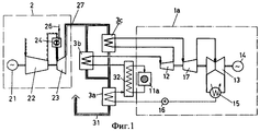
Наиболее близким к предлагаемому способу является способ перегрева пара на АЭС с помощью газотурбинной установки [3] (фиг.1), при котором выхлопные газы после газовой турбины 23 направляют в пароперегреватели высокого 3b и среднего давления 3с, а также в подогреватель питательной воды 3а, поступающей в реактор 11а. В пароперегревателе высокого давления 3b насыщенный пар нагревается до 500-510°С, расширяясь в ЦВД 12 пар вновь становится влажным, затем направляется в пароперегреватель среднего давления 3с, где его температура вновь повышается до 500°С, и далее последовательно проходит через цилиндр среднего давления (ЦСД) 17 и цилиндр низкого давления 13. На последних ступенях цилиндра низкого давления влажность пара составляет около 4-7%. В этом состоянии пар поступает в конденсатор 15, образовавшийся в конденсаторе конденсат перекачивается в подогреватель питательной воды 3а, подогретая вода поступает в парогенератор 32.Closest to the proposed method is a method of superheating steam at a nuclear power plant using a gas turbine unit [3] (Fig. 1), in which the exhaust gases after the
Недостаткам известного решения, принятого за прототип, является сравнительно невысокий КПД цикла, обусловленный ограниченной температурой перегрева пара и наличием влажного пара в цилиндре низкого давления. Наличие двух пароперегревателей с длинными трубопроводами удорожает устройство. Кроме того, при использовании для перегрева пара после реактора АЭС выхлопных газов высокотемпературной газовой турбины работоспособность всей станции ставится в зависимость от работы газотурбинного блока, имеющего сравнительно низкий ресурс работы. При его остановке паротурбинная часть станции, соединенная с реактором, вынуждена работать с очень высокой влажностью на всех ступенях (до 24% в последних ступенях) в глубоко нерасчетных режимах, что неизбежно ведет к быстрому выходу из строя всего лопаточного аппарата турбин. Эта опасность особенно велика для схемы, рассматриваемой в [5], где предлагается снизить температуру пара за реактором и подавать в пароперегреватель высокого давления 3b влажный пар.The disadvantages of the known solutions adopted for the prototype is the relatively low cycle efficiency due to the limited temperature of the superheat of the steam and the presence of wet steam in the low-pressure cylinder. The presence of two superheaters with long piping increases the cost of the device. In addition, when using the exhaust gases of a high-temperature gas turbine for superheating the steam after the reactor, the efficiency of the entire station is dependent on the operation of the gas-turbine unit, which has a relatively low service life. When it stops, the steam-turbine part of the station, connected to the reactor, is forced to work with very high humidity at all stages (up to 24% in the last stages) in deeply off-design modes, which inevitably leads to the rapid failure of the entire turbine blade apparatus. This danger is especially great for the scheme considered in [5], where it is proposed to lower the temperature of the steam behind the reactor and to supply wet steam to the high-
Для устранения отмеченных недостатков предлагается повысить начальную температуру пара во внешнем по отношению к реактору котле-пароперегревателе до уровня, при котором за последней ступенью паровой турбины влажность пара не будет превышать 0,5-1,0%. Этому условию для используемых на АЭС начальных давлениях пара соответствует начальная температура пара, равная 800-850°С.To eliminate the noted drawbacks, it is proposed to increase the initial temperature of the steam in the boiler superheater external to the reactor to a level at which the steam humidity will not exceed 0.5-1.0% beyond the last stage of the steam turbine. This condition for the initial vapor pressures used at nuclear power plants corresponds to an initial vapor temperature of 800-850 ° C.
Техническая задача, решаемая изобретением, состоит в повышении мощности и КПД АЭС путем увеличения располагаемого перепада энтальпий на всю паровую турбину при сохранении существующей мощности реактора за счет введения высокотемпературного перегрева пара от внешнего источника тепловой энергии, причем верхний уровень температуры перегрева пара не должен превышать указанной выше величины (850°С).The technical problem solved by the invention is to increase the power and efficiency of nuclear power plants by increasing the available enthalpy drop across the entire steam turbine while maintaining the existing reactor power by introducing high-temperature superheating of the steam from an external source of thermal energy, and the upper level of the superheating temperature of the steam should not exceed the above values (850 ° C).
Поставленная техническая задача решается тем, что в известном способе повышения КПД двухконтурной атомной станции путем перегрева пара после реакторного парогенератора этот перегрев осуществляют в котле-пароперегревателе с независимым источником тепловой энергии, с последующей подачей перегретого пара в турбину, состоящую из цилиндра высокого давления, цилиндра среднего давления и цилиндра низкого давления, затем направляемого в конденсатор, с перекачкой конденсата в реакторный парогенератор, согласно изобретению в котле-пароперегревателе температуру пара повышают до 800-850°С, при которой из последней ступени цилиндра низкого давления получают насыщенный пар со степенью сухости не менее 99% или слабо перегретый пар с температурой перегрева не более 5°С.The stated technical problem is solved in that in the known method of increasing the efficiency of a dual-circuit nuclear power plant by superheating the steam after the reactor steam generator, this superheating is carried out in a superheater with an independent source of thermal energy, followed by supplying superheated steam to the turbine, consisting of a high-pressure cylinder, an average cylinder pressure and low pressure cylinder, then sent to the condenser, with condensate pumping to the reactor steam generator, according to the invention in a steam boiler revatele steam temperature was increased to 800-850 ° C, at which from the last stage of the low pressure cylinder is obtained saturated steam having a degree of dryness of at least 99% or slightly superheated steam superheat temperature not exceeding 5 ° C.
На фиг.1 представлен известный способ повышения КПД и мощности двухконтурной атомной станции, в котором перегрев пара на АЭС осуществляется с помощью газотурбинной установки.Figure 1 presents a known method of increasing the efficiency and power of a dual-circuit nuclear power plant in which superheating of steam at a nuclear power plant is carried out using a gas turbine plant.
На фиг.2 представлен первый вариант тепловой схемы устройства двухконтурной атомной электростанции с высокотемпературным перегревом пара в котле-пароперегревателе для реализации предлагаемого способа, на фиг.3 - второй вариант тепловой схемы предлагаемого устройства двухконтурной атомной электростанции с высокотемпературным перегревом пара в водородной камере сгорания для реализации предлагаемого способа, на фиг.4 - тепловая схема предлагаемого устройства двухконтурной атомной электростанции с высокотемпературным перегревом пара в котле-пароперегревателе с турбодетандерной установкой для реализации предлагаемого способа, на фиг.5 - hs-диаграмма, иллюстрирующая процессы расширения пара в турбине обычной АЭС и устройства АЭС с внешним пароперегревателем для реализации предлагаемого способа.Figure 2 presents the first variant of the thermal diagram of the device of a dual-circuit nuclear power plant with high-temperature superheating of steam in a boiler superheater for implementing the proposed method, figure 3 is a second variant of the thermal diagram of the proposed device of a dual-circuit nuclear power plant with high-temperature superheating of steam in a hydrogen combustion chamber for implementation of the proposed method, figure 4 is a thermal diagram of the proposed device of a dual-circuit nuclear power plant with high-temperature superheating of steam in a boiler superheater with a turbo-expander for implementing the proposed method, Fig. 5 is an hs diagram illustrating steam expansion processes in a turbine of a conventional nuclear power plant and an NPP device with an external superheater for implementing the proposed method.
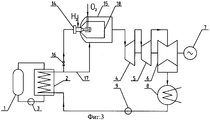
Блок атомной станции для реализации предлагаемого способа (фиг.2) содержит последовательно соединенные реактор 1, реакторный парогенератор 2, циркуляционный насос 3, а также турбину, состоящую из высокотемпературного цилиндра высокого давления 4, цилиндра среднего давления 5 и цилиндра низкого давления 6, валом соединенных с генератором 7, конденсатор 8, питательный насос 9, котел-пароперегреватель 10, независимый источник тепловой энергии 11, воздухоподогреватель 12, подключенный к нему вентилятор 13. При этом первый вход котла-пароперегревателя 10 по пару соединен с выходом парогенератора 2, а выход пароперегревателя по пару - с входом в высокотемпературный цилиндр высокого давления 4. Второй выход котла-пароперегревателя 10 по продуктам сгорания соединен с другим входом воздухоподогревателя 12, второй вход котла-перегревателя 10 соединен с независимым источником тепловой энергии 11, третий его вход по воздуху - с выходом воздухоподогревателя 12.The unit of the nuclear power plant for implementing the proposed method (Fig. 2) contains a series-connected
Устройство для реализации предлагаемого способа работает следующим образом. В первом контуре вода, нагретая в реакторе 1 под действием напора, созданного циркуляционным насосом 3, поступает в парогенератор 2, где отдает свою теплоту теплоносителю второго контура. Сухой насыщенный или слабо перегретый пар после парогенератора 2 поступает в котел-пароперегреватель 10, где за счет сгорания любого органического или иного топлива подводимого от независимого источника тепловой энергии 11 осуществляется необходимый перегрев пара. После котла-пароперегревателя 10 пар при температуре t0=800-850°C и давлении Р0=6,6 МПа направляется в высокотемпературный цилиндр высокого давления (ЦВД) 4. Затем он перепускается в цилиндр среднего давления (ЦСД) 5, за которым поддерживается давление, характерное для давления за ЦВД обычной влажно-паровой турбины. Цилиндр низкого давления (ЦНД) 6 остается без изменения. После ЦНД пар поступает в конденсатор 8. Из конденсатора питательным насосом 9 вода подается в парогенератор 2. Продукты сгорания после котла-пароперегревателя 10 по второму выходу подаются на вход в воздухоподогреватель 12, где используются для подогрева воздуха, куда он подается вентилятором 13.A device for implementing the proposed method works as follows. In the first circuit, the water heated in the
Таким образом, при использовании рассматриваемой схемы, сохраняется все существующее реакторное оборудование. Дополнительно к нему устанавливается котел-пароперегреватель 10 с воздухоподогревателем 12 и вентилятором 13. В турбинном цехе существующий цилиндр высокого давления меняется на два новых цилиндра - высокотемпературный ЦВД и ЦСД. Наиболее металлоемкий ЦНД 6 сохраняется от исходной турбины.Thus, when using the considered scheme, all existing reactor equipment is saved. In addition to it, a
При этом за счет резкого увеличения температуры перегретого пара в котле-пароперегревателе до 800-850°С существенно увеличивается внутренний относительный КПД турбины, так как в данном случае все ее ступени работают в области перегретого пара и потери от влажности, характерные для всех турбин АЭС, практически отсутствуют. Следует особо отметить, что для принятых сейчас давлений пара во втором контуре АЭС (6,6 МПа) перегрев пара свыше 850°С не ведет к увеличению экономичности, так как в этом случае из турбины выходит перегретый пар, который до начала конденсации необходимо охладить, выводя из цикла тем самым значительное количество тепловой энергии.At the same time, due to a sharp increase in the temperature of superheated steam in the superheater to 800-850 ° С, the internal relative efficiency of the turbine increases significantly, since in this case all its stages work in the area of superheated steam and moisture losses typical of all turbines of nuclear power plants, practically absent. It should be especially noted that for the steam pressures now accepted in the second circuit of the NPP (6.6 MPa), steam overheating above 850 ° C does not lead to an increase in efficiency, since in this case superheated steam comes out of the turbine, which must be cooled before condensation starts, thereby removing a significant amount of thermal energy from the cycle.
Увеличение начальной температуры пара до указанных выше значений ведет к росту термического КПД АЭС и на 60% увеличивает располагаемый перепад энтальпий. Примерно на те же 60% увеличивается и мощность турбины, без увеличения расхода пара через второй контур АЭС.An increase in the initial temperature of the vapor to the above values leads to an increase in the thermal efficiency of the nuclear power plant and increases the available enthalpy drop by 60%. The turbine power also increases by about the same 60%, without increasing the steam flow through the second circuit of the nuclear power plant.
Больший эффект может быть достигнут при использовании для перегрева пара на АЭС водородного топлива. В этом случае одновременно с повышением температуры пара увеличивается примерно на 20% и его расход, т.к. продуктом сгорания водорода является перегретый пар. При использовании в качестве топлива водорода котел-перегреватель 10 (фиг.2) заменяется специальной водородной камерой сгорания, принцип работы которой совпадает с принципом работы камеры сгорания газовой турбины.A greater effect can be achieved when using hydrogen fuel for superheating steam at nuclear power plants. In this case, at the same time as the temperature rises, the steam increases by about 20% and its consumption, because the product of hydrogen combustion is superheated steam. When using hydrogen as a fuel, the superheater 10 (Fig. 2) is replaced by a special hydrogen combustion chamber, the principle of operation of which coincides with the principle of operation of the combustion chamber of a gas turbine.
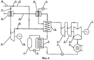
По второму варианту тепловая схема предлагаемого технического решения будет выглядеть так, как это показано на фиг.3.According to the second option, the thermal circuit of the proposed technical solution will look like that shown in Fig.3.
Устройство для реализации предлагаемого способа повышения КПД двухконтурной атомной электростанции с высокотемпературным перегревом пара содержит последовательно соединенные реактор 1 парогенератор 2, циркуляционный насос 3, подсоединенную через водородную форсунку 14 к выходу парогенератора 2 водородную камеру сгорания 15, турбину, состоящую из высокотемпературного цилиндра высокого давления 4, цилиндра среднего давления 5 и цилиндра низкого давления 6, валом соединенных с генератором 7, конденсатор 8, установленный на выходе цилиндра низкого давления 6, подключенный через питательный насос 9 к входу парогенератора 2. Выход парогенератора 2 по пару одновременно соединен с входом в водородную форсунку 14 водородной камеры сгорания 15 через вентиль 16 и при помощи паропровода 17 с внутренним пространством водородной камеры сгорания 15, выход водородной камеры сгорания 15 по пару соединен с входом в цилиндр высокого давления 4.A device for implementing the proposed method for increasing the efficiency of a dual-circuit nuclear power plant with high-temperature superheating of steam contains a series-connected
Работа осуществляется следующим образом. Сухой насыщенный пар после парогенератора 2 через вентиль 16 подводится к водородной форсунке 14 водородной камеры сгорания 15 при температуре около 280°С. Сюда же подается водород и кислород. При сгорании водорода в паровой атмосфере образуется перегретый пар с температурой порядка 1600°С. Затем, как и в обычной камере сгорания, высокотемпературный пар смешивается с основным сухим насыщенным паром, который подводится в камеру смешения 18 водородной камеры сгорания по паропроводу 17. При этом на выходе из водородной камеры сгорания устанавливается оптимальная с точки зрения работы турбины и цикла в целом температура пара, равная 800-850°С.The work is as follows. Dry saturated steam after the
При использовании в качестве независимого источника тепловой энергии для перегрева пара природного газа предлагаемое устройство может быть дополнено турбодетандерной установкой (фиг.4), содержащей турбодетандер 14, соединенный валом с генератором электроэнергии 15, подогреватель природного газа 16, первый вход которого через первую задвижку 17 подключен к магистральному трубопроводу 18, первый выход подогревателя природного газа 16 по газу соединен с входом в турбодетандер 14, второй вход его по продуктам сгорания - с выходом воздухоподогревателя 12 при помощи газопровода 19, вход в котел-пароперегреватель 10 по газу через вторую задвижку 20 соединен с выходом турбодетандера 14 и одновременно через третью задвижку 21, установленную на газопроводе 22, с магистральным трубопроводом 18.When using the natural gas as an independent source of thermal energy for superheating steam, the proposed device can be supplemented with a turboexpander unit (Fig. 4) containing a
В этом случае природный газ после первой задвижки 17 направляется в подогреватель природного газа 16, где его температура повышается до 80-90°С. Подогретый в подогревателе 16 природный газ поступает в турбодетандер 14, соединенный с генератором 15, и, расширяясь в ступенях турбодетандера 14 до необходимого для работы форсунок котла-пароперегревателя 10 давления, совершает дополнительную выработку электроэнергии. При таком совмещении турбодетандерного цикла с основным тепловым циклом АЭС возможно дальнейшее увеличение на 1,0-1,5% абсолютного КПД рассматриваемой станции.In this case, natural gas after the
После котла-пароперегревателя 10 пар при температуре t0=825°C и давлении Р0=6,6 МПа направляется в первый высокотемпературный цилиндр высокого давления (ЦВД) 4. Затем он перепускается в цилиндр среднего давления (ЦСД) 5, за которым поддерживается давление, характерное для давления за ЦВД обычной влажно-паровой турбины. Цилиндр низкого давления (ЦНД) 6 остается без изменений. После ЦНД пар поступает в конденсатор 8. Из конденсатора питательным насосом 9 вода подается в парогенератор 2.After the superheater, 10 steam at a temperature of t 0 = 825 ° C and a pressure of P 0 = 6.6 MPa is sent to the first high-temperature high-pressure cylinder (CVP) 4. Then it is transferred to a medium-pressure cylinder (TsSD) 5, which is then supported pressure characteristic of the pressure behind the CVP of a conventional wet-steam turbine. Low pressure cylinder (LPC) 6 remains unchanged. After the low-pressure cylinder, steam enters the
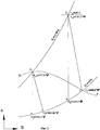
Процесс перегрева пара в пароперегревателе до оптимальной температуры иллюстрируется соответствующими линиями на hs-диаграмме (фиг.5), где h01 - энтальпия сухого насыщенного пара после парогенератора 2 (фиг.2), h1t - энтальпия пара за турбиной при отсутствии потерь энергии, h1 - энтальпия пара за турбиной при реальном расширении пара в турбине, h02 - энтальпия пара после котла-пароперегревателя 10 (фиг.2), h2t - энтальпия пара за турбиной предлагаемого устройства АЭС при отсутствии потерь, h2 - энтальпия пара за турбиной при реальном расширении для предлагаемого устройства АЭС. На фиг.5 изображены процессы расширения пара в турбине обычной АЭС (линия O1-1) и предлагаемого устройства АЭС с котлом-пароперегревателем (линия O2-2). Линия А-А представляет собой пограничную кривую, отделяющую область влажного пара (область ниже кривой А-А) от области сухого пара. Точка O1 соответствует состоянию пара после реакторного парогенератора 2 (фиг.2) перед турбиной обычного блока АЭС, работающего при давлении пара, равном Р0=6,6 МПа и почти нулевой влажности y=0. Этой точке соответствует энтальпия h01=2777,6 кДж/кг. Пар с указанными параметрами поступает в котел-пароперегреватель 10 (фиг.2), где при постоянном давлении Р0=6,6 МПа к нему подводится тепло, и его температура непрерывно повышается до некоторого значения t02 (т.О2 на фиг.5). Эта температура перегрева, как уже отмечалось выше, определяется из условия получения за последней ступенью ЦНД насыщенного пара при заданном давлении Рк в конденсаторе (в данном случае Рк=4 кПа).The process of steam overheating in the superheater to the optimum temperature is illustrated by the corresponding lines in the hs diagram (Fig. 5), where h 01 is the enthalpy of dry saturated steam after the steam generator 2 (Fig. 2), h 1t is the enthalpy of steam behind the turbine in the absence of energy loss, h 1 - enthalpy of steam behind the turbine with real expansion of the steam in the turbine, h 02 - enthalpy of steam after the boiler superheater 10 (Fig. 2), h 2t - enthalpy of steam behind the turbine of the proposed NPP device in the absence of losses, h 2 - enthalpy of steam behind real expansion turbine for pre proposed device NPP. Figure 5 shows the expansion processes of steam in the turbine of a conventional nuclear power plant (line O 1 -1) and the proposed device NPP with a boiler superheater (line O 2 -2). Line AA is a boundary curve separating the wet steam region (the region below curve AA) from the dry steam region. Point O 1 corresponds to the state of steam after the reactor steam generator 2 (Fig. 2) in front of the turbine of a conventional NPP unit operating at a steam pressure of P 0 = 6.6 MPa and almost zero humidity y = 0. Enthalpy h 01 = 2777.6 kJ / kg corresponds to this point. Steam with the indicated parameters enters the superheater 10 (Fig. 2), where at a constant pressure P 0 = 6.6 MPa heat is supplied to it, and its temperature continuously rises to a certain value t 02 (i.e., O 2 in FIG. 5). This superheat temperature, as already noted above, is determined from the condition of obtaining saturated steam behind the last stage of the low-pressure cylinder at a given pressure P k in the condenser (in this case P k = 4 kPa).
Нахождение температуры пара после котла-пароперегревателя велось из условия, что внутренний КПД турбины будет равен ηoi=0,9. Принятое значение КПД паровой турбины обусловлено тем, что в предлагаемом устройстве АЭС все ее ступени работают в области перегретого пара и, следовательно, потери от влажности отсутствуют.The temperature of the steam after the superheater was determined from the condition that the internal efficiency of the turbine would be η oi = 0.9. The accepted value of the efficiency of a steam turbine is due to the fact that in the proposed NPP device all its stages operate in the area of superheated steam and, therefore, there are no losses from humidity.
В то же время для влажно-паровых турбин ![]()
![]()
![]()
![]()
Для сравниваемых вариантов yср=0.132 (точка 1, фиг.5) [1] и при ![]()
![]()
Для указанных значений КПД и существующих на АЭС параметрах пара температура после парогенератора должна быть повышена до температуры t0=825°C в котле-пароперегревателе с независимым источником тепловой энергии.For the indicated efficiency values and the steam parameters existing at the NPP, the temperature after the steam generator should be increased to a temperature of t 0 = 825 ° C in a steam boiler with an independent source of thermal energy.
По предварительным оценкам КПД присоединенного теплового цикла, полностью осуществляемого в области перегретого пара, достигает 60%, что позволяет поднять КПД нового блока АЭС, по сравнению с существующим блоком, на 8-10%.According to preliminary estimates, the efficiency of the attached heat cycle, fully implemented in the area of superheated steam, reaches 60%, which allows to increase the efficiency of the new NPP unit by 8-10% compared to the existing unit.
При этом за счет увеличения располагаемого перепада энтальпий достигается увеличение мощности нового блока примерно на 60%, по сравнению с существующим блоком АЭС.At the same time, due to the increase in the available enthalpy difference, an increase in the power of the new unit by about 60% is achieved in comparison with the existing NPP unit.
При использовании для перегрева пара водородного топлива одновременно с ростом располагаемого перепада энтальпий на 20% увеличивается и расход пара через турбину. Соответственно общее увеличение мощности блока может достичь 80%.When using hydrogen fuel for superheating steam simultaneously with an increase in the available enthalpy drop by 20%, the steam flow through the turbine also increases. Accordingly, the total increase in power of the unit can reach 80%.
Источники информацииInformation sources
1. Трояновский Б.М., Филиппов Г.А., Булкин А.Е. Паровые и газовые турбины атомных электростанций. М.: Энергоатомиздат, 1985 год.1. Troyanovsky B.M., Filippov G.A., Bulkin A.E. Steam and gas turbines of nuclear power plants. M .: Energoatomizdat, 1985.
2. Deutsches Patentamt DE 3021965 A1 G21D 5/16 Offenlegungstag 17.12.81.2. Deutsches Patentamt DE 3021965
3. Europalsche Patentschreft 0424 660 В1 G21D 5/16 Veroffentlichungstag der Patentschreft 20.12.95 Patentblatt 95/51.3. Europalsche Patentschreft 0424 660
4. European Patent Specification 0128252 B1 G21D 5/16, F22G 1/16. Date of publication of patent specification 10.06.87.4. European Patent Specification 0128252
5. International Publication Number: WO 95/32509 G21D 5/16, F01K 3/18. International Publication Date: 30.11.95.5. International Publication Number: WO 95/32509
Claims (1)
Priority Applications (1)
| Application Number | Priority Date | Filing Date | Title |
|---|---|---|---|
| RU2006129783/06A RU2335641C2 (en) | 2006-08-17 | 2006-08-17 | Method of enhancing efficiency and output of two-loop nuclear power station |
Applications Claiming Priority (1)
| Application Number | Priority Date | Filing Date | Title |
|---|---|---|---|
| RU2006129783/06A RU2335641C2 (en) | 2006-08-17 | 2006-08-17 | Method of enhancing efficiency and output of two-loop nuclear power station |
Publications (2)
| Publication Number | Publication Date |
|---|---|
| RU2006129783A RU2006129783A (en) | 2008-02-27 |
| RU2335641C2 true RU2335641C2 (en) | 2008-10-10 |
Family
ID=39278479
Family Applications (1)
| Application Number | Title | Priority Date | Filing Date |
|---|---|---|---|
| RU2006129783/06A RU2335641C2 (en) | 2006-08-17 | 2006-08-17 | Method of enhancing efficiency and output of two-loop nuclear power station |
Country Status (1)
| Country | Link |
|---|---|
| RU (1) | RU2335641C2 (en) |
Cited By (5)
| Publication number | Priority date | Publication date | Assignee | Title |
|---|---|---|---|---|
| RU2499952C2 (en) * | 2011-08-22 | 2013-11-27 | Федеральное государственное бюджетное образовательное учреждение высшего профессионального образования "Кузбасский государственный технический университет имени Т.Ф. Горбачева" (КузГТУ) | Steam generator and method to produce high-temperature water steam |
| WO2014204347A1 (en) * | 2013-06-20 | 2014-12-24 | Ivanuk Viktor Nikolaevich | Hybrid atomic power station |
| RU2550362C1 (en) * | 2014-01-22 | 2015-05-10 | Виктор Николаевич Иванюк | Device for increase of efficiency and power of transportable nuclear power plant |
| RU2661231C1 (en) * | 2017-09-28 | 2018-07-13 | Рашид Зарифович Аминов | Method of hydrogen steam overheating at npp |
| RU2736603C1 (en) * | 2019-08-15 | 2020-11-19 | Артём Николаевич Байрамов | System for safe use of hydrogen while increasing power of double-circuit npp above nominal |
Families Citing this family (1)
| Publication number | Priority date | Publication date | Assignee | Title |
|---|---|---|---|---|
| CN106523044B (en) * | 2016-12-22 | 2019-02-22 | 广东核电合营有限公司 | The cylinder temperature acceleration cooling method of steam turbine for nuclear power station high intermediate pressure cylinder |
-
2006
- 2006-08-17 RU RU2006129783/06A patent/RU2335641C2/en not_active IP Right Cessation
Non-Patent Citations (1)
| Title |
|---|
| Маневренные паротурбинные блоки за рубежом. Энергетическое оборудование. - М.: НИИИНФОРМТЯЖМАШ, 1972. * |
Cited By (6)
| Publication number | Priority date | Publication date | Assignee | Title |
|---|---|---|---|---|
| RU2499952C2 (en) * | 2011-08-22 | 2013-11-27 | Федеральное государственное бюджетное образовательное учреждение высшего профессионального образования "Кузбасский государственный технический университет имени Т.Ф. Горбачева" (КузГТУ) | Steam generator and method to produce high-temperature water steam |
| WO2014204347A1 (en) * | 2013-06-20 | 2014-12-24 | Ivanuk Viktor Nikolaevich | Hybrid atomic power station |
| RU2550362C1 (en) * | 2014-01-22 | 2015-05-10 | Виктор Николаевич Иванюк | Device for increase of efficiency and power of transportable nuclear power plant |
| WO2015112054A1 (en) * | 2014-01-22 | 2015-07-30 | Виктор Николаевич ИВАНЮК | Transportable nuclear power plant |
| RU2661231C1 (en) * | 2017-09-28 | 2018-07-13 | Рашид Зарифович Аминов | Method of hydrogen steam overheating at npp |
| RU2736603C1 (en) * | 2019-08-15 | 2020-11-19 | Артём Николаевич Байрамов | System for safe use of hydrogen while increasing power of double-circuit npp above nominal |
Also Published As
| Publication number | Publication date |
|---|---|
| RU2006129783A (en) | 2008-02-27 |
Similar Documents
| Publication | Publication Date | Title |
|---|---|---|
| RU2335641C2 (en) | Method of enhancing efficiency and output of two-loop nuclear power station | |
| RU2525569C2 (en) | Combined-cycle topping plant for steam power plant with subcritical steam parameters | |
| RU2409746C2 (en) | Steam-gas plant with steam turbine drive of compressor and regenerative gas turbine | |
| RU2003102313A (en) | METHOD FOR OPERATING ATOMIC STEAM TURBINE INSTALLATION AND INSTALLATION FOR ITS IMPLEMENTATION | |
| RU2650238C1 (en) | Gas distribution station power plant or the gas control unit operation method | |
| KR101753526B1 (en) | Combined cycle power generation system | |
| KR101935637B1 (en) | Combined cycle power generation system | |
| RU2561770C2 (en) | Operating method of combined-cycle plant | |
| CN104594964A (en) | Novel single-shaft natural gas combined cycle heat supply unit system | |
| RU126373U1 (en) | STEAM GAS INSTALLATION | |
| RU2533601C2 (en) | Power plant with combined-cycle plant | |
| RU2476690C2 (en) | Method of combined cycle plant operation | |
| RU2328045C2 (en) | Method of operating atomic steam-turbine power generating system and equipment for implementing method | |
| EP2519717A2 (en) | Combined-cycle plant for the production of electric and thermal energy and method for operating said plant | |
| RU2309264C1 (en) | Method of power generation in steam-gas power plant | |
| RU2420664C2 (en) | Multi-mode heat extraction plant | |
| RU167924U1 (en) | Binary Combined Cycle Plant | |
| RU2756880C1 (en) | Combined gas and steam unit of a power plant with parallel operation | |
| JPH09209713A (en) | Steam cooling combined cycle plant | |
| RU2605879C2 (en) | Power plant combined-cycle plant | |
| RU2773410C1 (en) | Combined cycle gas plant | |
| RU2768325C1 (en) | Thermal power plant | |
| RU2795147C1 (en) | Combined-cycle plant with a semi-closed gas turbine plant | |
| RU2261337C1 (en) | Power and heating plant with open power and heat supply system | |
| RU2324823C1 (en) | Method of working of thermal electrical station |
Legal Events
| Date | Code | Title | Description |
|---|---|---|---|
| PC4A | Invention patent assignment |
Effective date: 20100210 |
|
| MM4A | The patent is invalid due to non-payment of fees |
Effective date: 20150818 |