RU2773410C1 - Combined cycle gas plant - Google Patents
Combined cycle gas plant Download PDFInfo
- Publication number
- RU2773410C1 RU2773410C1 RU2021127735A RU2021127735A RU2773410C1 RU 2773410 C1 RU2773410 C1 RU 2773410C1 RU 2021127735 A RU2021127735 A RU 2021127735A RU 2021127735 A RU2021127735 A RU 2021127735A RU 2773410 C1 RU2773410 C1 RU 2773410C1
- Authority
- RU
- Russia
- Prior art keywords
- pressure
- medium
- low
- superheater
- drum
- Prior art date
Links
- XLYOFNOQVPJJNP-UHFFFAOYSA-N water Substances O XLYOFNOQVPJJNP-UHFFFAOYSA-N 0.000 claims abstract description 33
- 238000002485 combustion reaction Methods 0.000 claims abstract description 17
- 239000007789 gas Substances 0.000 claims description 59
- 239000002918 waste heat Substances 0.000 claims description 7
- 230000000694 effects Effects 0.000 abstract description 3
- 238000011084 recovery Methods 0.000 abstract 1
- 239000000126 substance Substances 0.000 abstract 1
- 238000009835 boiling Methods 0.000 description 6
- 238000010438 heat treatment Methods 0.000 description 4
- 238000000605 extraction Methods 0.000 description 3
- 239000000446 fuel Substances 0.000 description 2
- 239000008236 heating water Substances 0.000 description 2
- 238000004140 cleaning Methods 0.000 description 1
- 239000002826 coolant Substances 0.000 description 1
- 239000000498 cooling water Substances 0.000 description 1
- 230000005611 electricity Effects 0.000 description 1
- 230000003628 erosive Effects 0.000 description 1
- 239000001301 oxygen Substances 0.000 description 1
- MYMOFIZGZYHOMD-UHFFFAOYSA-N oxygen Chemical compound O=O MYMOFIZGZYHOMD-UHFFFAOYSA-N 0.000 description 1
- 229910052760 oxygen Inorganic materials 0.000 description 1
- 239000002245 particle Substances 0.000 description 1
Images
Abstract
Description
Изобретение относится к теплоэнергетике, а именно к устройствам для выработки электрической энергии, и может быть использовано в тепловых электростанциях.The invention relates to thermal power engineering, namely to devices for generating electrical energy, and can be used in thermal power plants.
Известна тепловая электрическая станция [Патент RU № 2691881 от 18.06.19 г.], содержащая паротурбинный блок, состоящий из парового котла, связанного через пароперегреватель с цилиндром высокого давления паротурбинного блока, который механически связан с цилиндром низкого давления паротурбинного блока, цилиндр высокого давления паротурбинного блока связан, в свою очередь, с промежуточным пароперегревателем, с третьим и первым подогревателями высокого давления по горячей стороне, деаэратором и четвертым подогревателем низкого давления по горячей стороне через отборы, а также с цилиндром низкого давления паротурбинного блока, который является приводом для электрогенератора паротурбинного блока, промежуточный пароперегреватель связан с цилиндром высокого давления паротурбинного блока, цилиндр низкого давления паротурбинного блока связан с первым, вторым и третьим подогревателями низкого давления по горячей стороне через отборы и конденсатором паротурбинного блока, конденсатор паротурбинного блока связан с конденсатным насосом паротурбинного блока, конденсатный насос паротурбинного блока связан с первым подогревателем низкого давления по холодной стороне, первый, второй, третий и четвертый подогреватели низкого давления последовательно связаны друг с другом по холодной стороне, четвертый подогреватель низкого давления по холодной стороне связан с деаэратором, деаэратор через питательный насос паротурбинного блока связан с первым подогревателем высокого давления по холодной стороне, первый подогреватель высокого давления по горячей стороне связан с деаэратором, а по холодной – со вторым подогревателем высокого давления, второй подогреватель высокого давления по горячей стороне связан с первым подогревателем высокого давления, а по холодной – с третьим подогревателем высокого давления, третий подогреватель высокого давления по горячей стороне связан со вторым подогревателем высокого давления, а по холодной – с паровым котлом, при этом второй подогреватель высокого давления по горячей стороне также связан с барабаном среднего давления парогазового блока, а конденсатный насос паротурбинного блока также связан с конденсатным насосом парогазового блока, состоящего из компрессора, связанного через камеру сгорания с газовой турбиной, которая является приводом для первого электрогенератора парогазового блока, газовая турбина связана с котлом-утилизатором, который, в свою очередь, состоит из пароперегревателя высокого давления, связанного по горячей стороне с испарителем высокого давления, а по холодной – с цилиндром высокого давления парогазового блока, который механически связан с цилиндром среднего давления парогазового блока, испаритель высокого давления по горячей стороне связан с пароперегревателем среднего давления, а по холодной – с барабаном высокого давления парогазового блока, пароперегреватель среднего давления по горячей стороне связан с испарителем среднего давления, а по холодной – с цилиндром среднего давления парогазового блока, который механически связан с цилиндром низкого давления парогазового блока, испаритель среднего давления по горячей стороне связан с пароперегревателем низкого давления, а по холодной – с барабаном среднего давления парогазового блока, пароперегреватель низкого давления по горячей стороне связан с экономайзером высокого давления, а по холодной – с цилиндром среднего давления парогазового блока, экономайзер высокого давления по горячей стороне соединен с экономайзером среднего давления, а по холодной – с барабаном высокого давления парогазового блока, экономайзер среднего давления по горячей стороне связан с испарителем низкого давления, а по холодной – с барабаном среднего давления парогазового блока, испаритель низкого давления по горячей стороне связан с газовым подогревателем конденсата, а по холодной – с барабаном низкого давления парогазового блока, газовый подогреватель конденсата по горячей стороне связан с атмосферой, а по холодной – с барабаном низкого давления парогазового блока, барабан низкого давления парогазового блока по водяному пространству связан с испарителем низкого давления и через питательные насосы среднего и высокого давлений парогазового блока с экономайзерами среднего и высокого давлений соответственно, а по паровому пространству – с пароперегревателем низкого давления, барабан среднего давления парогазового блока по водяному пространству связан с испарителем среднего давления, а по паровому – с пароперегревателем среднего давления, барабан высокого давления парогазового блока по водяному пространству связан с испарителем высокого давления, а по паровому – с пароперегревателем высокого давления, цилиндр высокого давления парогазового блока связан с пароперегревателем среднего давления, цилиндр среднего давления парогазового блока связан с цилиндром низкого давления парогазового блока, цилиндр низкого давления парогазового блока, который является приводом для второго электрогенератора парогазового блока, связан с конденсатором парогазового блока, конденсатор парогазового блока связан с конденсатным насосом парогазового блока, конденсатный насос парогазового блока связан с газовым подогревателем конденсата. Known thermal power plant [Patent RU No. 2691881 dated 18.06.19], containing a steam turbine unit, consisting of a steam boiler connected through a superheater with a high pressure cylinder of the steam turbine unit, which is mechanically connected to the low pressure cylinder of the steam turbine unit, the high pressure cylinder of the steam turbine unit block is connected, in turn, with an intermediate superheater, with the third and first high-pressure heaters on the hot side, a deaerator and a fourth low-pressure heater on the hot side through the selections, as well as with the low-pressure cylinder of the steam turbine unit, which is the drive for the electric generator of the steam turbine unit , the intermediate superheater is connected to the high pressure cylinder of the steam turbine unit, the low pressure cylinder of the steam turbine unit is connected to the first, second and third low pressure heaters on the hot side through the extraction and condenser of the steam turbine unit, the condenser of the steam turbine o of the unit is connected to the condensate pump of the steam turbine unit, the condensate pump of the steam turbine unit is connected to the first low pressure heater on the cold side, the first, second, third and fourth low pressure heaters are connected in series to each other on the cold side, the fourth low pressure heater is connected to the cold side with a deaerator, the deaerator is connected to the first high pressure heater on the cold side through the feed pump of the steam turbine unit, the first high pressure heater is connected to the deaerator on the hot side, and to the second high pressure heater on the cold side, the second high pressure heater is connected to the first one on the hot side high-pressure heater, and on the cold side - with the third high-pressure heater, the third high-pressure heater is connected on the hot side to the second high-pressure heater, and on the cold side - to the steam boiler, while the second high-pressure heater on the hot side is also connected to the medium pressure drum of the combined cycle unit, and the condensate pump of the steam turbine unit is also connected to the condensate pump of the combined cycle gas unit, which consists of a compressor connected through the combustion chamber to the gas turbine, which is the drive for the first electric generator of the combined cycle gas unit, the gas turbine is connected to waste heat boiler, which, in turn, consists of a high-pressure superheater connected on the hot side to the high-pressure evaporator, and on the cold side to the high-pressure cylinder of the combined-cycle unit, which is mechanically connected to the medium-pressure cylinder of the combined-cycle unit, the high-pressure evaporator the hot side is connected to the medium pressure superheater, and on the cold side - to the high pressure drum of the steam-gas unit, the medium-pressure superheater is connected on the hot side to the medium pressure evaporator, and on the cold side - to the medium pressure cylinder of the steam-gas unit, which is mechanically It is tightly connected to the low-pressure cylinder of the combined-cycle unit, the medium-pressure evaporator is connected on the hot side to the low-pressure superheater, and on the cold side to the medium-pressure drum of the combined-cycle unit, the low-pressure superheater is connected to the high-pressure economizer on the hot side, and to the cylinder on the cold side medium-pressure economizer of the combined-cycle unit, the high-pressure economizer is connected on the hot side to the medium-pressure economizer, and on the cold side to the high-pressure drum of the combined-cycle unit, the medium-pressure economizer is connected on the hot side to the low-pressure evaporator, and on the cold side to the medium-pressure drum of the combined-cycle unit , the low-pressure evaporator is connected on the hot side to the gas condensate heater, and on the cold side - to the low-pressure drum of the steam-gas unit, the gas-fired condensate heater is connected to the atmosphere on the hot side, and to the low-pressure drum of the steam-gas unit, the drum is neither high-pressure steam-gas unit is connected via the water space to the low-pressure evaporator and through the medium and high pressure feed pumps of the steam-gas unit with medium and high pressure economizers, respectively, and through the steam space - to the low-pressure superheater, the medium-pressure drum of the steam-gas unit is connected via the water space to medium-pressure evaporator, and through steam - with a medium-pressure superheater, the high-pressure drum of the steam-gas unit is connected to the high-pressure evaporator through the water space, and through the steam space - to the high-pressure superheater, the high-pressure cylinder of the steam-gas unit is connected to the medium-pressure superheater, the medium-pressure cylinder of the combined-cycle unit is connected to the low-pressure cylinder of the combined-cycle unit, the low-pressure cylinder of the combined-cycle unit, which is the drive for the second electric generator of the combined-cycle unit, is connected to the condenser of the combined-cycle unit, condensate OR of the combined-cycle unit is connected to the condensate pump of the combined-cycle unit, the condensate pump of the combined-cycle unit is connected to the gas condensate heater.
Недостатком известной тепловой электрической станции является пониженный срок эксплуатации проточной части цилиндра низкого давления парогазового блока, что связано с высокой влажностью пара в нем.A disadvantage of the known thermal power plant is the reduced life of the flow part of the low-pressure cylinder of the combined-cycle unit, which is associated with the high humidity of the steam in it.
Известна тепловая электрическая станция [Патент RU № 2749800 от 17.06.21 г.], содержащая паротурбинный блок, состоящий из парового котла, связанного через пароперегреватель с цилиндром высокого давления паротурбинного блока, который механически связан с цилиндром низкого давления паротурбинного блока, цилиндр высокого давления паротурбинного блока связан, в свою очередь, с промежуточным пароперегревателем, с третьим и первым подогревателями высокого давления по горячей стороне, деаэратором и четвертым подогревателем низкого давления по горячей стороне через отборы, а также с цилиндром низкого давления паротурбинного блока, который является приводом для электрогенератора паротурбинного блока, промежуточный пароперегреватель связан с цилиндром высокого давления паротурбинного блока, цилиндр низкого давления паротурбинного блока связан с первым, вторым и третьим подогревателями низкого давления по горячей стороне через отборы и конденсатором паротурбинного блока, конденсатор паротурбинного блока связан с конденсатным насосом паротурбинного блока, конденсатный насос паротурбинного блока связан с первым подогревателем низкого давления по холодной стороне и с конденсатным насосом парогазового блока, первый, второй, третий и четвертый подогреватели низкого давления последовательно связаны друг с другом по холодной стороне, четвертый подогреватель низкого давления по холодной стороне связан с деаэратором, который через питательный насос паротурбинного блока связан с первым подогревателем высокого давления по холодной стороне, первый подогреватель высокого давления по горячей стороне связан с деаэратором, а по холодной – со вторым подогревателем высокого давления, второй подогреватель высокого давления по горячей стороне связан с первым подогревателем высокого давления и с барабаном среднего давления парогазового блока, а по холодной – с третьим подогревателем высокого давления, третий подогреватель высокого давления по горячей стороне связан со вторым подогревателем высокого давления, а по холодной – с паровым котлом, при этом цилиндр низкого давления паротурбинного блока также связан через отбор, к которому подключен второй подогреватель низкого давления, с подогревателем сетевой воды по горячей стороне, подогреватель сетевой воды по горячей стороне через дренажный насос связан с третьим подогревателем низкого давления, а по холодной стороне – с потребителем тепла, который, в свою очередь, связан с сетевым электронасосом, а сетевой электронасос связан с подогревателем сетевой воды по холодной стороне, и парогазовый блок, состоящий из компрессора, связанного через камеру сгорания с газовой турбиной, которая является приводом для первого электрогенератора парогазового блока, газовая турбина связана с котлом-утилизатором, который, в свою очередь, состоит из пароперегревателя высокого давления, связанного по горячей стороне с испарителем высокого давления, а по холодной – с цилиндром высокого давления парогазового блока, который механически связан с цилиндром среднего давления парогазового блока, испаритель высокого давления по горячей стороне связан с пароперегревателем среднего давления, а по холодной – с барабаном высокого давления парогазового блока, пароперегреватель среднего давления по горячей стороне связан с испарителем среднего давления, а по холодной – с цилиндром среднего давления парогазового блока, который механически связан с цилиндром низкого давления парогазового блока, испаритель среднего давления по горячей стороне связан с пароперегревателем низкого давления, а по холодной – с барабаном среднего давления парогазового блока, пароперегреватель низкого давления по горячей стороне связан с экономайзером высокого давления, а по холодной – с цилиндром среднего давления парогазового блока, экономайзер высокого давления по горячей стороне соединен с экономайзером среднего давления, а по холодной – с барабаном высокого давления парогазового блока, экономайзер среднего давления по горячей стороне связан с испарителем низкого давления, а по холодной – с барабаном среднего давления парогазового блока, испаритель низкого давления по горячей стороне связан с газовым подогревателем конденсата, а по холодной – с барабаном низкого давления парогазового блока, газовый подогреватель конденсата по горячей стороне связан с атмосферой, а по холодной – с барабаном низкого давления парогазового блока, барабан низкого давления парогазового блока по водяному пространству связан с испарителем низкого давления и через питательные насосы среднего и высокого давлений парогазового блока с экономайзерами среднего и высокого давлений соответственно, а по паровому пространству – с пароперегревателем низкого давления, барабан среднего давления парогазового блока по водяному пространству связан с испарителем среднего давления, а по паровому – с пароперегревателем среднего давления, барабан высокого давления парогазового блока по водяному пространству связан с испарителем высокого давления, а по паровому – с пароперегревателем высокого давления, цилиндр высокого давления парогазового блока связан с пароперегревателем среднего давления, цилиндр среднего давления парогазового блока связан с цилиндром низкого давления парогазового блока, цилиндр низкого давления парогазового блока, который является приводом для второго электрогенератора парогазового блока, связан с конденсатором парогазового блока, конденсатор парогазового блока связан с конденсатным насосом парогазового блока, конденсатный насос парогазового блока связан с газовым подогревателем конденсата. Known thermal power plant [Patent RU No. 2749800 dated 06/17/21], containing a steam turbine unit, consisting of a steam boiler connected through a superheater with a high pressure cylinder of the steam turbine unit, which is mechanically connected to the low pressure cylinder of the steam turbine unit, the high pressure cylinder of the steam turbine unit block is connected, in turn, with an intermediate superheater, with the third and first high-pressure heaters on the hot side, a deaerator and a fourth low-pressure heater on the hot side through the selections, as well as with the low-pressure cylinder of the steam turbine unit, which is the drive for the electric generator of the steam turbine unit , the intermediate superheater is connected to the high pressure cylinder of the steam turbine unit, the low pressure cylinder of the steam turbine unit is connected to the first, second and third low pressure heaters on the hot side through the extraction and condenser of the steam turbine unit, the condenser of the steam turbine o of the unit is connected to the condensate pump of the steam turbine unit, the condensate pump of the steam turbine unit is connected to the first low pressure heater on the cold side and to the condensate pump of the combined cycle unit, the first, second, third and fourth low pressure heaters are connected in series to each other on the cold side, the fourth heater low pressure on the cold side is connected to the deaerator, which through the feed pump of the steam turbine unit is connected to the first high pressure heater on the cold side, the first high pressure heater is connected to the deaerator on the hot side, and on the cold side to the second high pressure heater, the second high pressure heater on the hot side it is connected to the first high-pressure heater and to the medium-pressure drum of the steam-gas unit, and on the cold side - to the third high-pressure heater, the third high-pressure heater on the hot side is connected to the second high-pressure heater. on the cold side - with the steam boiler, while the low-pressure cylinder of the steam turbine unit is also connected through the extraction, to which the second low-pressure heater is connected, with the heating water heater on the hot side, the heating water heater on the hot side through the drain pump is connected to a third low-pressure heater, and on the cold side - with a heat consumer, which, in turn, is connected to the network electric pump, and the network electric pump is connected to the network water heater on the cold side, and a combined-cycle unit consisting of a compressor connected through a combustion chamber with gas turbine, which is the drive for the first electric generator of the gas-steam unit, the gas turbine is connected to the waste heat boiler, which, in turn, consists of a high-pressure superheater connected on the hot side to the high-pressure evaporator, and on the cold side to the high-pressure cylinder of the steam-gas block that is mechanically connected to the cylinder ohm of medium pressure of the steam-gas unit, the high-pressure evaporator is connected on the hot side to the medium-pressure superheater, and on the cold side - to the high-pressure drum of the steam-gas unit, the medium-pressure superheater on the hot side is connected to the medium-pressure evaporator, and on the cold side - to the medium-pressure cylinder of the steam-gas unit unit, which is mechanically connected to the low-pressure cylinder of the steam-gas unit, the medium-pressure evaporator is connected on the hot side to the low-pressure superheater, and on the cold side - to the medium-pressure drum of the steam-gas unit, the low-pressure superheater is connected to the high-pressure economizer on the hot side, and on the cold side – with the medium pressure cylinder of the combined cycle unit, the high pressure economizer is connected on the hot side to the medium pressure economizer, and on the cold side to the high pressure drum of the combined cycle unit, the medium pressure economizer on the hot side is connected to the low pressure evaporator yes on the cold side - with the medium pressure drum of the steam-gas unit, the low-pressure evaporator is connected on the hot side to the gas condensate heater, and on the cold side - to the low-pressure drum of the steam-gas unit, the gas condensate heater on the hot side is connected to the atmosphere, and on the cold side - with the low-pressure drum of the steam-gas unit, the low-pressure drum of the steam-gas unit is connected through the water space to the low-pressure evaporator and through the medium and high pressure feed pumps of the steam-gas unit with the medium and high pressure economizers, respectively, and through the steam space - to the low-pressure superheater, the medium drum pressure of the steam-gas unit through the water space is connected to the medium pressure evaporator, and through the steam - to the medium pressure superheater, the high-pressure drum of the steam-gas unit is connected to the high-pressure evaporator through the water space, and through the steam - to the high-pressure superheater. pressure, the high pressure cylinder of the combined cycle unit is connected to the medium pressure steam superheater, the medium pressure cylinder of the combined cycle gas unit is connected to the low pressure cylinder of the combined cycle unit, the low pressure cylinder of the combined cycle unit, which is the drive for the second electric generator of the combined cycle unit, is connected to the condenser of the combined cycle unit, the condenser of the combined cycle gas block is connected to the condensate pump of the combined cycle unit, the condensate pump of the combined cycle unit is connected to the gas condensate heater.
Недостатком известной тепловой электрической станции является пониженный срок эксплуатации проточной части цилиндра низкого давления парогазового блока, что связано с высокой влажностью пара в нем.A disadvantage of the known thermal power plant is the reduced life of the flow part of the low-pressure cylinder of the combined-cycle unit, which is associated with the high humidity of the steam in it.
Задачей изобретения является усовершенствование парогазовой установки, позволяющее увеличить срок эксплуатации парогазовой установки и повысить ее электрический коэффициент полезного действия.The objective of the invention is to improve the combined cycle plant, allowing to increase the service life of the combined cycle plant and increase its electrical efficiency.
Технический результат заключается в повышении надежности и термодинамической эффективности парогазовой установки.The technical result consists in increasing the reliability and thermodynamic efficiency of the combined cycle plant.
Технический результат достигается тем, что парогазовая установка содержит компрессор, связанный через камеру сгорания с газовой турбиной, которая является приводом для первого электрогенератора, газовая турбина связана с котлом-утилизатором, который, в свою очередь, состоит из пароперегревателя высокого давления, связанного по горячей стороне с испарителем высокого давления, а по холодной – с цилиндром высокого давления, который механически связан с цилиндром среднего давления, испаритель высокого давления по горячей стороне связан с пароперегревателем среднего давления, а по холодной – с барабаном высокого давления, пароперегреватель среднего давления по горячей стороне связан с испарителем среднего давления, а по холодной – с цилиндром среднего давления, который механически связан с цилиндром низкого давления, испаритель среднего давления по горячей стороне связан с пароперегревателем низкого давления, а по холодной – с барабаном среднего давления, пароперегреватель низкого давления по горячей стороне связан с экономайзером высокого давления, а по холодной – с цилиндром среднего давления, экономайзер высокого давления по горячей стороне соединен с экономайзером среднего давления, а по холодной – с барабаном высокого давления, экономайзер среднего давления по горячей стороне связан с испарителем низкого давления, а по холодной – с барабаном среднего давления, испаритель низкого давления по горячей стороне связан с газовым подогревателем конденсата, а по холодной – с барабаном низкого давления, газовый подогреватель конденсата по горячей стороне связан с атмосферой, а по холодной – с барабаном низкого давления, барабан низкого давления по водяному пространству связан с испарителем низкого давления и через питательные насосы среднего и высокого давлений с экономайзерами среднего и высокого давлений соответственно, а по паровому пространству – с пароперегревателем низкого давления, барабан среднего давления по водяному пространству связан с испарителем среднего давления, а по паровому – с пароперегревателем среднего давления, барабан высокого давления по водяному пространству связан с испарителем высокого давления, а по паровому с пароперегревателем высокого давления, цилиндр высокого давления связан с пароперегревателем среднего давления, цилиндр среднего давления связан с цилиндром низкого давления, цилиндр низкого давления, который является приводом для второго электрогенератора, связан с конденсатором, конденсатор связан с конденсатным насосом, конденсатный насос связан с газовым подогревателем конденсата, при этом между цилиндрами среднего и низкого давлений установлен дополнительный промежуточный пароперегреватель, связанный по холодной стороне с циркуляционным насосом, циркуляционный насос связан с группой солнечных коллекторов, группа солнечных коллекторов связана с дополнительным пароперегревателем. The technical result is achieved by the fact that the combined cycle plant contains a compressor connected through a combustion chamber to a gas turbine, which is the drive for the first electric generator, the gas turbine is connected to a waste heat boiler, which, in turn, consists of a high-pressure superheater connected along the hot side with a high-pressure evaporator, and on the cold side - with a high-pressure cylinder, which is mechanically connected to the medium pressure cylinder, the high-pressure evaporator is connected on the hot side to the medium pressure superheater, and on the cold side - to the high pressure drum, the medium pressure superheater is connected on the hot side with the medium pressure evaporator, and on the cold side - with the medium pressure cylinder, which is mechanically connected to the low pressure cylinder, the medium pressure evaporator is connected on the hot side to the low pressure superheater, and on the cold side - to the medium pressure drum, low pressure superheater on the hot side it is connected to the high pressure economizer, and on the cold side it is connected to the medium pressure cylinder, the high pressure economizer is connected on the hot side to the medium pressure economizer, and on the cold side to the high pressure drum, the medium pressure economizer on the hot side is connected to the low pressure evaporator , and on the cold side - with a medium pressure drum, the low pressure evaporator is connected on the hot side to the gas condensate heater, and on the cold side - to the low pressure drum, the gas condensate heater on the hot side is connected to the atmosphere, and on the cold side - to the low pressure drum, the low pressure drum is connected through the water space to the low pressure evaporator and through the medium and high pressure feed pumps to the medium and high pressure economizers, respectively, and through the steam space to the low pressure superheater, the medium pressure drum is connected to the medium pressure evaporator through the water space steam, and with a medium pressure superheater, the high pressure drum is connected with the high pressure evaporator through the water space, and with the high pressure superheater through the steam space, the high pressure cylinder is connected to the medium pressure superheater, the medium pressure cylinder is connected to the low pressure cylinder, the cylinder low pressure, which is the drive for the second electric generator, is connected to the condenser, the condenser is connected to the condensate pump, the condensate pump is connected to the gas condensate heater, while an additional intermediate superheater is installed between the medium and low pressure cylinders, connected on the cold side to the circulation pump, circulation the pump is connected to the solar collector group, the solar collector group is connected to an additional superheater.
Введение в схему парогазовой установки дополнительного промежуточного пароперегревателя, с которым по горячей стороне сообщен цилиндр среднего давления и который сообщен по горячей стороне с цилиндром низкого давления, а по холодной последовательно – с циркуляционным насосом и группой солнечных коллекторов, позволяет повысить надежность и термодинамическую эффективность, что приводит к увеличению срока эксплуатации парогазовой установки и повышению ее электрического коэффициента полезного действия.The introduction of an additional intermediate superheater into the scheme of the combined cycle plant, with which the medium pressure cylinder is connected on the hot side and which is connected on the hot side with the low pressure cylinder, and on the cold side in series with the circulation pump and a group of solar collectors, makes it possible to increase the reliability and thermodynamic efficiency, which leads to an increase in the service life of the combined cycle plant and an increase in its electrical efficiency.
Полезный эффект заключается в повышении степени сухости пара в проточной части цилиндра низкого давления парогазовой установки за счет дополнительного промежуточного перегрева пара перед цилиндром низкого давления, который происходит путем передачи теплоты пару от группы солнечных коллекторов. Это позволяет снизить эрозионное воздействие частиц влаги на его лопатки цилиндра низкого давления, что повышает срок их службы и надежность работы.The beneficial effect is to increase the degree of steam dryness in the flow path of the low-pressure cylinder of the combined-cycle plant due to additional intermediate overheating of the steam in front of the low-pressure cylinder, which occurs by transferring heat to the steam from a group of solar collectors. This reduces the erosive effect of moisture particles on its low-pressure cylinder blades, which increases their service life and reliability.
Повышение степени сухости и дополнительный подвод теплоты без сжигания дополнительного количества топлива окажут положительное влияние на коэффициент полезного действия паровой турбины, а значит и на КПД парогазовой установки в целом.An increase in the degree of dryness and an additional supply of heat without burning an additional amount of fuel will have a positive effect on the efficiency of the steam turbine, and hence on the efficiency of the combined cycle plant as a whole.
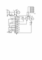
На фигуре изображена парогазовая установка, которая состоит из компрессора 1, связанного через камеру сгорания 2 с газовой турбиной 3, которая является приводом для первого электрогенератора 4. Газовая турбина 3 связана с котлом-утилизатором 5, который, в свою очередь, состоит из пароперегревателя высокого давления 6, связанного по горячей стороне с испарителем высокого давления 7, а по холодной – с цилиндром высокого давления 9, который механически связан с цилиндром среднего давления 11, испаритель высокого давления 7 по горячей стороне связан с пароперегревателем среднего давления 10, а по холодной – с барабаном высокого давления 8, пароперегреватель среднего давления 10 по горячей стороне связан с испарителем среднего давления 12, а по холодной – с цилиндром среднего давления 11, который механически связан с цилиндром низкого давления 25, испаритель среднего давления 12 по горячей стороне связан с пароперегревателем низкого давления 14, а по холодной – с барабаном среднего давления 13, пароперегреватель низкого давления 14 по горячей стороне связан с экономайзером высокого давления 15, а по холодной – с цилиндром среднего давления 11, экономайзер высокого давления 15 по горячей стороне соединен с экономайзером среднего давления 16, а по холодной – с барабаном высокого давления 8, экономайзер среднего давления 16 по горячей стороне связан с испарителем низкого давления 17, а по холодной – с барабаном среднего давления 13, испаритель низкого давления 17 по горячей стороне связан с газовым подогревателем конденсата 18, а по холодной – с барабаном низкого давления 19, газовый подогреватель конденсата 18 по горячей стороне связан с атмосферой, а по холодной – с барабаном низкого давления 19, барабан низкого давления 19 по водяному пространству связан с испарителем низкого давления 17 и через питательные насосы среднего 20 и высокого 21 давлений с экономайзерами среднего 16 и высокого 15 давлений соответственно, а по паровому пространству – с пароперегревателем низкого давления 14, барабан среднего давления 13 по водяному пространству связан с испарителем среднего давления 12, а по паровому – с пароперегревателем среднего давления 10, барабан высокого давления 8 по водяному пространству связан с испарителем высокого давления 7, а по паровому – с пароперегревателем высокого давления 6, цилиндр высокого давления 9 связан с пароперегревателем среднего давления 10, цилиндр среднего давления 11 связан с цилиндром низкого давления 25, цилиндр низкого давления 25, который является приводом для второго электрогенератора 26, связан с конденсатором 27, конденсатор 27 связан с конденсатным насосом 28, конденсатный насос 28 связан с газовым подогревателем конденсата 18, между цилиндрами среднего 11 и низкого 25 давлений установлен дополнительный промежуточный пароперегреватель 22, связанный по холодной стороне с циркуляционным насосом 23, циркуляционный насос 23 связан с группой солнечных коллекторов 24, группа солнечных коллекторов 24 связана с дополнительным пароперегревателем 22. The figure shows a combined-cycle plant, which consists of a compressor 1 connected through a combustion chamber 2 with a gas turbine 3, which is the drive for the first electric generator 4. The gas turbine 3 is connected to the waste heat boiler 5, which, in turn, consists of a superheater of high pressure 6, connected on the hot side with the high pressure evaporator 7, and on the cold side - with the
Парогазовая установка работает следующим образом. Воздух, сжатый в компрессоре 1, подается в камеру сгорания 2, в которой сжигается газообразное топливо. Из камеры сгорания 2 продукты сгорания попадают в газовую турбину 3, являющуюся приводом для компрессора 1 и первого электрогенератора 4. Выхлопные газы, из газовой турбины 3, поступают котел-утилизатор 5. Здесь они отдают свою теплоту на перегрев пара в пароперегревателе высокого давления 6, на кипение котловой воды в испарителе высокого давления 7, на перегрев пара в пароперегревателе среднего давления 10, на кипение котловой воды в испарителе среднего давления 12, на перегрев пара в пароперегревателе низкого давления 14, на подогрев питательной воды в экономайзере высокого давления 15, на подогрев питательной воды в экономайзере среднего давления 16, на кипение котловой воды в испарителе низкого давления 17, на подогрев потока основного конденсата в газовом подогревателе 18. Из котла-утилизатора 5 продукты сгорания направляются в атмосферу. Поток конденсата из конденсатора 27 поступает на вход конденсатного насоса 28. Далее основной поток конденсата конденсатным насосом 28 направляется в газовый подогреватель конденсата 18, где подогревается за счет теплоты уходящих газов. Из газового подогревателя конденсата 18 основной поток конденсата подается в барабан низкого давления 19, который надстроен деаэрационной головкой, где очищается от кислорода и других неконденсируемых газов и смешивается с его котловой водой. Из барабана низкого давления 19 часть котловой воды направляется в испаритель низкого давления 17, где происходит кипение за счет теплоты продуктов сгорания. Из испарителя низкого давления 17 сухой насыщенный пар подается в паровое пространство барабана низкого давления 19. Другая часть котловой воды из барабана низкого давления 19 питательными насосами среднего 20 и высокого 21 давлений направляется в экономайзеры среднего 16 и высокого 15 давлений соответственно. Сухой насыщенный пар из барабана низкого давления 19 подается в пароперегреватель низкого давления 14, где перегревается за счет теплоты продуктов сгорания. Из пароперегревателя низкого давления 14 перегретый пар направляется в цилиндр среднего давления 11, который является приводом для второго электрогенератора 26, где смешивается с частично отработавшим потоком основного пара. Из экономайзера среднего давления 16 питательная вода подается в барабан среднего давления 13, где смешивается с его котловой водой. Из барабана среднего давления 13 котловая вода направляется в испаритель среднего давления 12, где происходит кипение за счет теплоты продуктов сгорания. Из испарителя среднего давления 12 сухой насыщенный пар подается в паровое пространство барабана среднего давления 13. Сухой насыщенный пар из барабана среднего давления 13, предварительно смешавшись с потоком основного пара из цилиндра высокого давления 9, подается в пароперегреватель среднего давления 10, где перегревается за счет теплоты продуктов сгорания. Из экономайзера высокого давления 15 питательная вода подается в барабан высокого давления 8, где смешивается с его котловой водой. Из барабана высокого давления 8 котловая вода направляется в испаритель высокого давления 7, где происходит кипение за счет теплоты продуктов сгорания. Из испарителя высокого давления 7 сухой насыщенный пар подается в паровое пространство барабана высокого давления 8. Из барабана высокого давления 8 сухой насыщенный пар направляется в пароперегреватель высокого давления 6, где перегревается за счет теплоты продуктов сгорания. Из пароперегревателя высокого давления 6 перегретый пар подается в цилиндр высокого давления 9, который является приводом для второго электрогенератора 26. Из цилиндра высокого давления 9 поток основного пара направляется в пароперегреватель среднего давления 10, где к нему подмешивается пар из барабана среднего давления 13, и перегревается за счет теплоты продуктов сгорания. Из пароперегревателя среднего давления 10 перегретый пар подается на вход цилиндра среднего давления 11, который является приводом для второго электрогенератора 26. Из цилиндра среднего давления 11 поток основного пара направляется в дополнительный промежуточный пароперегреватель 22, где подогревается за счет теплоты, полученной от группы солнечных коллекторов 24. Из дополнительного промежуточного пароперегревателя 22 поток основного пара направляется в цилиндр низкого давления 25, который является приводом для второго электрогенератора 26. Из цилиндра низкого давления 25 поток основного пара подается в конденсатор 27, где конденсируется, отдавая свою теплоту охлаждающей воде. Теплоноситель после дополнительного промежуточного пароперегревателя 22 с помощью циркуляционного насоса 23 снова подается в группу солнечных коллекторов 24 для нагрева.Combined-cycle plant works as follows. The air compressed in the compressor 1 is supplied to the combustion chamber 2, in which the gaseous fuel is burned. From the combustion chamber 2, the combustion products enter the gas turbine 3, which is the drive for the compressor 1 and the first electric generator 4. The exhaust gases from the gas turbine 3 enter the waste heat boiler 5. Here they give up their heat to superheat the steam in the high-pressure superheater 6, for boiler water boiling in the high pressure evaporator 7, for steam superheating in the
Таким образом, изобретение позволит повысить надежность и термодинамическую эффективность производства электроэнергии на парогазовой установке за счет дополнительного промежуточного перегрева пара после цилиндра среднего давления за счет теплоты, полученной от группы солнечных коллекторов.Thus, the invention will improve the reliability and thermodynamic efficiency of electricity generation in a combined cycle plant due to additional intermediate overheating of steam after the medium pressure cylinder due to the heat received from a group of solar collectors.
Claims (1)
Publications (1)
| Publication Number | Publication Date |
|---|---|
| RU2773410C1 true RU2773410C1 (en) | 2022-06-03 |
Family
ID=
Citations (3)
| Publication number | Priority date | Publication date | Assignee | Title |
|---|---|---|---|---|
| RU2232903C2 (en) * | 2000-02-15 | 2004-07-20 | Цой Константин Александрович | Catalytic thermal power station, catalytic reactor |
| RU2501958C2 (en) * | 2008-02-25 | 2013-12-20 | Сенер Групо Де Инхенерия, С.А. | Method of energy generation by means of thermodynamic cycles with water vapour of high pressure and moderate temperature |
| RU2749800C1 (en) * | 2020-10-09 | 2021-06-17 | Федеральное государственное бюджетное образовательное учреждение высшего образования "Кубанский государственный технологический университет" (ФГБОУ ВО "КубГТУ") | Thermal power station |
Patent Citations (3)
| Publication number | Priority date | Publication date | Assignee | Title |
|---|---|---|---|---|
| RU2232903C2 (en) * | 2000-02-15 | 2004-07-20 | Цой Константин Александрович | Catalytic thermal power station, catalytic reactor |
| RU2501958C2 (en) * | 2008-02-25 | 2013-12-20 | Сенер Групо Де Инхенерия, С.А. | Method of energy generation by means of thermodynamic cycles with water vapour of high pressure and moderate temperature |
| RU2749800C1 (en) * | 2020-10-09 | 2021-06-17 | Федеральное государственное бюджетное образовательное учреждение высшего образования "Кубанский государственный технологический университет" (ФГБОУ ВО "КубГТУ") | Thermal power station |
Similar Documents
| Publication | Publication Date | Title |
|---|---|---|
| RU2532635C2 (en) | Electric energy accumulation by thermal accumulator and reverse electric energy production by thermodynamic cyclic process | |
| RU2691881C1 (en) | Thermal power plant | |
| RU2525569C2 (en) | Combined-cycle topping plant for steam power plant with subcritical steam parameters | |
| RU156586U1 (en) | BINAR STEAM GAS INSTALLATION | |
| RU2335641C2 (en) | Method of enhancing efficiency and output of two-loop nuclear power station | |
| CN108843406A (en) | A kind of flue gas reheat formula dish-style photo-thermal and gas combustion-gas vapor combined cycle system | |
| JP3905967B2 (en) | Power generation / hot water system | |
| CN108708835A (en) | A kind of novel solar complementation association circulating power generation system of cooling burning machine inlet air | |
| RU2728312C1 (en) | Method of operation and device of manoeuvrable gas-steam cogeneration plant with steam drive of compressor | |
| RU2409746C2 (en) | Steam-gas plant with steam turbine drive of compressor and regenerative gas turbine | |
| RU2752123C1 (en) | Thermal power station | |
| RU2773410C1 (en) | Combined cycle gas plant | |
| CN109296413A (en) | A kind of the bypass double reheat power generator and method cooling using deep sea water | |
| RU2003102313A (en) | METHOD FOR OPERATING ATOMIC STEAM TURBINE INSTALLATION AND INSTALLATION FOR ITS IMPLEMENTATION | |
| RU2768325C1 (en) | Thermal power plant | |
| RU168003U1 (en) | Binary Combined Cycle Plant | |
| RU2776091C1 (en) | Thermal power plant | |
| RU167924U1 (en) | Binary Combined Cycle Plant | |
| RU2533601C2 (en) | Power plant with combined-cycle plant | |
| CN209369886U (en) | A kind of bypass double reheat power generator cooling using deep sea water | |
| RU2001132885A (en) | The method of operation of a combined cycle gas-fired power plant (solid with gaseous or liquid, or nuclear with gaseous or liquid) and a combined-cycle plant for its implementation | |
| RU2749800C1 (en) | Thermal power station | |
| CN209115164U (en) | The system of nuclear energy coupling gas turbine power generation based on depth UTILIZATION OF VESIDUAL HEAT IN | |
| RU2747786C1 (en) | Thermal power station | |
| RU2324823C1 (en) | Method of working of thermal electrical station |