RU2310503C1 - Method of the heat-energy-mass exchange and the device for the method realization - Google Patents
Method of the heat-energy-mass exchange and the device for the method realization Download PDFInfo
- Publication number
- RU2310503C1 RU2310503C1 RU2006137636/15A RU2006137636A RU2310503C1 RU 2310503 C1 RU2310503 C1 RU 2310503C1 RU 2006137636/15 A RU2006137636/15 A RU 2006137636/15A RU 2006137636 A RU2006137636 A RU 2006137636A RU 2310503 C1 RU2310503 C1 RU 2310503C1
- Authority
- RU
- Russia
- Prior art keywords
- vortex
- acoustic
- chamber
- parts
- flows
- Prior art date
Links
Images
Classifications
-
- B—PERFORMING OPERATIONS; TRANSPORTING
- B01—PHYSICAL OR CHEMICAL PROCESSES OR APPARATUS IN GENERAL
- B01J—CHEMICAL OR PHYSICAL PROCESSES, e.g. CATALYSIS OR COLLOID CHEMISTRY; THEIR RELEVANT APPARATUS
- B01J19/00—Chemical, physical or physico-chemical processes in general; Their relevant apparatus
- B01J19/26—Nozzle-type reactors, i.e. the distribution of the initial reactants within the reactor is effected by their introduction or injection through nozzles
-
- B—PERFORMING OPERATIONS; TRANSPORTING
- B01—PHYSICAL OR CHEMICAL PROCESSES OR APPARATUS IN GENERAL
- B01J—CHEMICAL OR PHYSICAL PROCESSES, e.g. CATALYSIS OR COLLOID CHEMISTRY; THEIR RELEVANT APPARATUS
- B01J19/00—Chemical, physical or physico-chemical processes in general; Their relevant apparatus
- B01J19/08—Processes employing the direct application of electric or wave energy, or particle radiation; Apparatus therefor
- B01J19/10—Processes employing the direct application of electric or wave energy, or particle radiation; Apparatus therefor employing sonic or ultrasonic vibrations
-
- B—PERFORMING OPERATIONS; TRANSPORTING
- B01—PHYSICAL OR CHEMICAL PROCESSES OR APPARATUS IN GENERAL
- B01J—CHEMICAL OR PHYSICAL PROCESSES, e.g. CATALYSIS OR COLLOID CHEMISTRY; THEIR RELEVANT APPARATUS
- B01J19/00—Chemical, physical or physico-chemical processes in general; Their relevant apparatus
- B01J19/24—Stationary reactors without moving elements inside
- B01J19/2405—Stationary reactors without moving elements inside provoking a turbulent flow of the reactants, such as in cyclones, or having a high Reynolds-number
-
- B—PERFORMING OPERATIONS; TRANSPORTING
- B01—PHYSICAL OR CHEMICAL PROCESSES OR APPARATUS IN GENERAL
- B01J—CHEMICAL OR PHYSICAL PROCESSES, e.g. CATALYSIS OR COLLOID CHEMISTRY; THEIR RELEVANT APPARATUS
- B01J2219/00—Chemical, physical or physico-chemical processes in general; Their relevant apparatus
- B01J2219/00049—Controlling or regulating processes
- B01J2219/00051—Controlling the temperature
- B01J2219/00074—Controlling the temperature by indirect heating or cooling employing heat exchange fluids
- B01J2219/00119—Heat exchange inside a feeding nozzle or nozzle reactor
Landscapes
- Chemical & Material Sciences (AREA)
- Organic Chemistry (AREA)
- Chemical Kinetics & Catalysis (AREA)
- Health & Medical Sciences (AREA)
- General Health & Medical Sciences (AREA)
- Toxicology (AREA)
- Physical Or Chemical Processes And Apparatus (AREA)
Abstract
Description
Изобретение относится к акустическим (например, ультразвуковым) способам тепломассоэнергообмена жидких, газовых, газожидкостных смесей, взвесей и дисперсий в механо-физико-химических процессах превращения, кроме этого, таким способом воздействуют на воду с целью нагрева ее как теплоносителя.The invention relates to acoustic (for example, ultrasonic) methods of heat and mass energy exchange of liquid, gas, gas-liquid mixtures, suspensions and dispersions in mechano-physical and chemical conversion processes, in addition, in this way they act on water to heat it as a coolant.
Известны способы тепломассоэнергообмена при акустическом возбуждении проходных потоков продуктов путем передачи жидкости колебательной энергии с помощью источника механических колебаний, взаимодействующего с жидкостью. Используется этот способ в гидродинамических ультразвуковых излучателях с пластинчатыми и стержневыми резонансными колебательными устройствами, в вихревых и роторно-пульсационных аппаратах. Другим способом тепломассоэнергообмена при акустическом возбуждении может быть взаимодействие струйных потоков между собой путем передачи кинетической энергии одного потока другому. Этот способ используется в струйно-вихревых аппаратах (инжекторах, вихревых трубах), в которых происходит преобразование потенциальной энергии в кинетическую с последующим тепломассоэнергообменом взаимодействующих сред. В результате такого взаимодействия возникает резонанс и кавитационный эффект, в результате чего рвутся связи между молекулами и атомами, при восстановлении которых выделяется энергия в виде тепла. На этой основе работают теплогенераторы.Known methods of heat and mass energy during the acoustic excitation of the flow of products through the transmission of liquid vibrational energy using a source of mechanical vibrations interacting with the liquid. This method is used in hydrodynamic ultrasonic emitters with plate and rod resonant oscillating devices, in vortex and rotary-pulsating devices. Another method of heat and mass energy exchange during acoustic excitation can be the interaction of jet streams with each other by transferring the kinetic energy of one stream to another. This method is used in jet-vortex devices (injectors, vortex tubes) in which the potential energy is converted into kinetic energy, followed by heat and mass transfer of interacting media. As a result of this interaction, a resonance and a cavitation effect arise, as a result of which bonds between molecules and atoms are broken, during the restoration of which energy is released in the form of heat. Heat generators work on this basis.
Известен способ резонансного возбуждения жидкости и устройство для нагревания жидкости [патент РФ 2232630, 7 B01J 19/10, опубликован 20.07.04], который основан на обработке жидкости источником механических колебаний на частоте из ряда основных частот, подчиняющихся определенной эмпирической зависимости. Способ нагревания жидкости основан на акустической обработке жидкости и включает ее подачу в полость вращающегося рабочего колеса и выпуск из полости через ряд выходных отверстий в периферийной кольцевой стенке рабочего колеса в кольцевую камеру, а затем в сборную камеру при соблюдении определенных соотношений между частотой вращения рабочего колеса, радиуса периферийной стенки и резонансной частоты. К недостаткам этого способа следует отнести сложность технической реализации этого способа, избирательность возбуждения, многофакторная зависимость резонансного возбуждения от геометрических, частотных параметров и ограниченная возможность использования этого способа для проведения других тепломассоэнергообменных процессов.There is a method of resonant excitation of a liquid and a device for heating the liquid [
Наиболее близким по технической сущности является способ тепломассоэнергообмена и устройство для его осуществления [патент РФ 2268772, 7 B01J 19/10, 7 B01 F 11/02, опубликован 27.01.2006], при котором возбуждение осуществляется с помощью сообщенных между собой вихревых труб путем частичного соприкосновения встречно направленных поверхностно-наружных слоев двух и более вихревых потоков на глубину, обеспечивающую их акустическое возбуждение за счет деформационного взаимодействия, происходящего в зоне пересечения вихревых труб. Устройство для осуществления этого способа выполнено в виде двух и более вихревых труб, сообщенных между собой с помощью частичного пересечения их по образующим.The closest in technical essence is the method of heat and mass energy exchange and a device for its implementation [
Однако этот способ и устройство имеют ряд недостатков. Во-первых, противоструйное взаимодействие на входе снижает эффективность процесса вихреформирования и уменьшает энергию вихревзаимодействия. Во-вторых, размещение пересекающихся вихревых труб вокруг центральной вихревой трубы не обеспечивает одинаковых условий сдвигового взаимодействия вихрей. В случае двухфазового ввода компонентов типа жидкость-газ подобное решение не обеспечивает стабильность процесса из-за неустановившегося режима струйного взаимодействия. Это приводит к деформации вихревых потоков, сопровождающихся низкочастотной вибрацией и гидроударами. Кроме этого, в выходной акустической камере, объединяющей вихревые трубы на выходе, происходит неэффективное разрушение потоков с точки зрения резонансного режима акустического воздействия на продукт.However, this method and device have several disadvantages. Firstly, the anti-jet interaction at the input reduces the efficiency of the vortex reforming process and reduces the vortex interaction energy. Secondly, the placement of intersecting vortex tubes around a central vortex tube does not provide the same conditions for shear interaction of vortices. In the case of two-phase input of components of the liquid-gas type, such a solution does not ensure the stability of the process due to the transient mode of jet interaction. This leads to deformation of the vortex flows, accompanied by low-frequency vibration and water hammer. In addition, in the output acoustic chamber combining the vortex tubes at the outlet, there is an ineffective destruction of the flows from the point of view of the resonant regime of acoustic exposure to the product.
Техническим результатом, на который направлено предлагаемое изобретение, является усовершенствование способа и устройства тепломассоэнергообмена по патенту РФ 2268772, а именно:The technical result, which the invention is directed to, is the improvement of the method and device for heat and mass and energy exchange according to the patent of the Russian Federation 2268772, namely:
- создание условий для эффективного вихреформирования как однокомпонентного жидкотекучего продукта, так и двух и более компонентных продуктов типа жидкость-жидкость, жидкость-газ;- creation of conditions for effective vortex reforming of a one-component fluid product, as well as two or more component products of the liquid-liquid, liquid-gas type;
- увеличение мощности акустического вихревзаимодействия;- increase the power of acoustic vortex interaction;
- концентрация энергии вихревого разрушения в выходной акустической камере для обеспечения дополнительного резонансного возбуждения.- concentration of vortex fracture energy in the output acoustic chamber to provide additional resonant excitation.
Технический результат достигается путем частичного соприкосновения встречно направленных поверхностно наружных слоев двух и более вихревых потоков на глубину, обеспечивающую возбуждение за счет деформационно-сдвигового взаимодействия, происходящего в зоне пересечения сообщенных между собой вихревых труб, расположенных по окружности по направлению продуктового потока и имеющих раздельные непересекающиеся входные части. При этом формируют раздельные непересекающиеся вихревые потоки по направлению продуктового потока, возбуждают их в кольцевом пространстве с помощью частичного пересечения вихревзаимодействующих частей вихревых труб и концентрируют энергию акустического возбуждения в выходной акустической камере путем частичного пересечения ее по образующим с вихревзаимодействующими частями вихревых труб. Обработанный звуком продуктовый поток выводят на использование.The technical result is achieved by partial contact of the counter-directed surface-outer layers of two or more vortex flows to a depth that provides excitation due to the deformation-shear interaction occurring in the intersection zone of the interconnected vortex tubes located around the circumference in the direction of the product stream and having separate non-intersecting input parts. In this case, separate disjoint eddy flows are formed in the direction of the product flow, excite them in the annular space by partially intersecting the vortex-interacting parts of the vortex tubes and concentrate the acoustic excitation energy in the output acoustic chamber by partially intersecting it along the generatrices with the vortex-interacting parts of the vortex tubes. The processed food stream is put to use.
Для осуществления настоящего способа предлагается устройство, содержащее напорную продуктовую камеру, вихревые трубы, сообщенные между собой с помощью частичного пересечения их по образующим и объединенные на выходе акустической камерой, вихревые трубы направлены по ходу течения продукта, расположены по окружности и состоят по форме из трех частей. Первая часть - входная, вихреформирующая; средняя часть - переходная и выходная часть - вихревзаимодействующая. Вихреформирующие части выполнены раздельными между собой и сообщены тангенциальными соплами с одной стороны с центральной камерой, расположенной по осевой, а с другой стороны - с кольцевой камерой, расположенной снаружи вихреформирующих частей вихревых труб. Переходные части выполнены коническими с вершинами, обращенными к вихреформирующей части. Вихревзаимодействующие части вихревых труб частично пересечены по образующим друг с другом и с акустической выходной камерой, расположенной по осевой, что создает концентрацию энергии дополнительного резонансного возбуждения в полости акустической камеры.To implement the present method, there is provided a device comprising a pressure product chamber, vortex tubes communicated with each other by partially intersecting them along generators and united at the outlet by an acoustic chamber, vortex tubes directed along the course of the product flow, located around the circumference and consist of three parts in shape . The first part is the input, vortex-forming; middle part - transitional and output part - vortex interacting. The vortex-forming parts are made separate from each other and communicated by tangential nozzles on one side with a central chamber located axially, and on the other hand, with an annular chamber located outside the vortex-forming parts of the vortex tubes. Transitional parts are made conical with vertices facing the vortex-forming part. The vortex-interacting parts of the vortex tubes are partially intersected along generatrix with each other and with an acoustic output chamber located axially, which creates an energy concentration of additional resonant excitation in the cavity of the acoustic chamber.
Предлагаемое техническое решение позволяет:The proposed technical solution allows you to:
- осуществить согласованный по направлению вращения ввод одного или двух компонентов, усреднение скоростей вводимых потоков без деформации гидродинамического режима вихреформирования и без отрицательного воздействия струйных потоков друг на друга;- to carry out the input of one or two components, coordinated in the direction of rotation, averaging the velocities of the introduced flows without deformation of the hydrodynamic regime of vortex reforming and without negative influence of the jet flows on each other;
- осуществить одинаковый гидродинамический режим начального взаимодействия вихрей в кольцевом пространстве частичного пересечения вихревзаимодействующих частей вихревых труб;- implement the same hydrodynamic regime of the initial interaction of vortices in the annular space of the partial intersection of the vortex interacting parts of the vortex tubes;
- произвести эффективное разрушение вихрей в выходной акустической камере путем дополнительного резонансного возбуждения за счет того, что выходная акустическая камера сообщена частичными пересечениями по образующим с вихревзаимодействующими частями вихревых труб.- to effectively destroy the vortices in the output acoustic chamber by means of additional resonant excitation due to the fact that the output acoustic chamber is communicated by partial intersections along the generatrices with the vortex interacting parts of the vortex tubes.
Возможны два варианта устройства. Первый вариант, когда напорные входные центральная и кольцевая камеры сообщены между собой общим пространством на входе - это обеспечивает вход одного продуктового компонента. Второй вариант, когда эти камеры выполнены раздельными, - это обеспечивает вход двух продуктов и их соединение в вихревом потоке.Two device options are possible. The first option, when the pressure input central and annular chambers are interconnected by a common space at the entrance, this ensures the entrance of one product component. The second option, when these chambers are made separate, it provides the entrance of two products and their connection in a vortex flow.
Эти и другие особенности настоящего изобретения будут понятны из нижеследующего описания примеров его осуществления со ссылками на прилагаемые чертежи.These and other features of the present invention will be apparent from the following description of examples of its implementation with reference to the accompanying drawings.
Краткое описание чертежей, на которых представлено:A brief description of the drawings, on which:
фиг.1 - условное изображение устройства с однопоточным вводом продукта;figure 1 - conditional image of the device with a single-threaded input of the product;
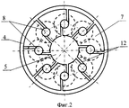
фиг.2 - условно изображен вид сверху по фиг.1 со снятой крышкой;figure 2 - conventionally depicted a top view of figure 1 with the cover removed;
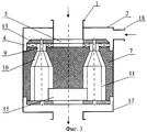
фиг.3 - условное изображение устройства с двухпоточным вводом компонентов;figure 3 - conditional image of the device with two-threaded input components;
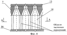
фиг.4 - условно изображена развертка размещения вихревых труб;figure 4 - conventionally depicted a scan of the placement of vortex tubes;
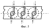
фиг.5 - вид сверху развертки размещения вихревых труб;5 is a top view of a scan of the placement of vortex tubes;
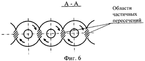
фиг.6 - сечение А-А развертки размещения вихревых труб по фиг.4.6 is a section aa scan swirl placement of the vortex tubes of figure 4.
На чертежах фиг.1, 2 условно изображен вариант устройства, состоящего из входного патрубка 1, корпуса 2, которые образуют напорную продуктовую камеру 3, сообщенную с кольцевой камерой 4 и центральной камерой 5. Корпус 2 соединен с вихревым блоком 6, состоящим из вихревой камеры 7, крышки 13 и кольцевого дна 16. В вихревой камере по окружности размещены вихревые трубы 8, каждая из которых состоит из входной вихреформирующей части 9, переходной конусообразной части 10 и выходной вихревзаимодействующей части 11, частично пересекающихся по образующим между собой. На входе вихреформирующие части 9 вихревых труб 8 сообщены с кольцевой камерой 4 и с центральной камерой 5 тангенциальными пазами 12. На верхней плоскости вихревой камеры 7 закреплена крышка 13, оформляющая тангенциальные сопловые вводы. По оси каждой вихревой трубы размещены вытеснители 14. В нижней части вихревая камера 7 содержит акустическую камеру 15, которая частично пересечена по образующим с вихревзаимодействующими частями 11 вихревых труб 8. К нижней части вихревой камеры 7 крепится кольцевое дно 16, которое оформляет акустическую камеру 15 как концентратор. Снизу к вихревому блоку 6 крепится выходной корпус 17 с выходным патрубком.The drawings of figures 1, 2 conventionally depict a variant of the device consisting of an inlet pipe 1, a
При варианте двухпоточного ввода компонентов (фиг.3) верхняя часть входного корпуса содержит дополнительный патрубок 18, а входной патрубок 1 разделяет кольцевую камеру 4 и центральную камеру 5, при этом входной патрубок 1 служит для ввода одного компонента, а дополнительный патрубок 18 для ввода другого компонента.In the variant of the two-line input of components (Fig. 3), the upper part of the input case contains an
Для описания работы устройства, в качестве примера, рассмотрим вариант исполнения, представленный на фигурах 1, 2, 4, 5, 6. Продукт под давлением подается через входной патрубок 1 в напорную камеру 3, которая распределяет его в кольцевую камеру 4 и центральную камеру 5. По тангенциальным сопловым пазам 12 продукт входит с двух сторон в вихреформирующие части 9 вихревых труб 8, которые обеспечивают вращение вихревых потоков. В этой части вихревых труб 8 происходит выравнивание скоростей потоков после струйных истечений, формирование стабильных и равнозначных по гидродинамическим режимам раздельных вихрей. Раздельные вихри в своем дальнейшем передвижении по спиралеобразной траектории через переходные конусообразные части 10 вихревых труб 8 переходят в вихревзаимодействующие части 11, сообщенные друг с другом с помощью частичных пересечений по образующим в последовательном порядке по окружности, образуя кольцевое пространство вихревзаимодействия. В результате этого происходит акустическое возбуждение продукта - ультразвуковая кавитация, что ведет, в итоге, к деструкции агрегатного состояния продукта и активизации химических связей. На выходе из вихревзаимодействующих частей 11 вихревых труб 8 в результате их частичного пересечения по образующим с полостью акустической камеры 15 происходит дополнительное возбуждение при разрушении вихрей в полости акустической камеры 15, т.е. происходит концентрация энергии в ограниченном пространстве. Это обстоятельство увеличивает эффективность тепломассоэнергообмена, ускоряет процессы физико-химических превращений. Обработанный продукт выводят на использование через выходной патрубок выходного корпуса 17.To describe the operation of the device, as an example, we consider the embodiment shown in figures 1, 2, 4, 5, 6. The product under pressure is supplied through the inlet pipe 1 to the pressure chamber 3, which distributes it to the
Аналогичным образом работает устройство, представленное, как вариант, на фиг.3. Отличием является то, что в разделенные кольцевую 4 и центральную 5 камеры подают разные компоненты. Например, в центральную камеру 5 подают водомучную суспензию, а в кольцевую - пар, в результате чего под воздействием температуры и ультразвукового возбуждения происходит мгновенная варка при низкой температуре, сопровождающаяся мгновенным извлечением крахмала для производства спирта.In a similar way, the device presented, as an option, in figure 3. The difference is that different components are fed into the divided annular 4 and central 5 chambers. For example, a volatile slurry is fed into the
Узлы и детали описанного устройства могут быть изготовлены на обычном оборудовании, что соответствует промышленной применимости изобретения.The nodes and parts of the described device can be manufactured on conventional equipment, which corresponds to the industrial applicability of the invention.
Таким образом, применение способа тепломассоэнергообмена и устройства для его осуществления позволяет сконцентрировать мощность акустического воздействия на продукт в ограниченном пространстве, увеличить объем и плотность кавитационного пространства.Thus, the use of heat and mass energy exchange method and device for its implementation allows you to concentrate the power of acoustic exposure to the product in a limited space, to increase the volume and density of cavitation space.
Claims (3)
Priority Applications (2)
| Application Number | Priority Date | Filing Date | Title |
|---|---|---|---|
| RU2006137636/15A RU2310503C1 (en) | 2006-10-25 | 2006-10-25 | Method of the heat-energy-mass exchange and the device for the method realization |
| PCT/RU2007/000584 WO2008051115A1 (en) | 2006-10-25 | 2007-10-23 | Heat-mass-and-energy exchange method and a device for carrying out said method |
Applications Claiming Priority (1)
| Application Number | Priority Date | Filing Date | Title |
|---|---|---|---|
| RU2006137636/15A RU2310503C1 (en) | 2006-10-25 | 2006-10-25 | Method of the heat-energy-mass exchange and the device for the method realization |
Publications (1)
| Publication Number | Publication Date |
|---|---|
| RU2310503C1 true RU2310503C1 (en) | 2007-11-20 |
Family
ID=38959330
Family Applications (1)
| Application Number | Title | Priority Date | Filing Date |
|---|---|---|---|
| RU2006137636/15A RU2310503C1 (en) | 2006-10-25 | 2006-10-25 | Method of the heat-energy-mass exchange and the device for the method realization |
Country Status (2)
| Country | Link |
|---|---|
| RU (1) | RU2310503C1 (en) |
| WO (1) | WO2008051115A1 (en) |
Cited By (3)
| Publication number | Priority date | Publication date | Assignee | Title |
|---|---|---|---|---|
| RU2462301C1 (en) * | 2011-03-10 | 2012-09-27 | Овченкова Оксана Анатольевна | Device for heat-mass-power exchange |
| RU2543182C2 (en) * | 2013-06-04 | 2015-02-27 | Сергей Николаевич Тумаков | Heat-mass-energy exchange method and device for its implementation |
| RU2658057C1 (en) * | 2017-09-11 | 2018-06-19 | Эль-Гадбан Илья Шакиб | Heat and mass energy exchange device |
Families Citing this family (1)
| Publication number | Priority date | Publication date | Assignee | Title |
|---|---|---|---|---|
| CN111867717B (en) | 2018-03-07 | 2021-07-06 | 沙伯环球技术有限公司 | Method and Reactor for Pyrolytic Conversion of Hydrocarbon Gas |
Citations (4)
| Publication number | Priority date | Publication date | Assignee | Title |
|---|---|---|---|---|
| WO1983000446A1 (en) * | 1981-07-28 | 1983-02-17 | SCHAUFFLER, Noël (deceased) | Method, devices and application for producing emulsions by ultra sonic whistles |
| SU1517987A1 (en) * | 1987-09-25 | 1989-10-30 | Ивано-Франковский Институт Нефти И Газа | Hydrodynamic powder disperser |
| WO2000042303A1 (en) * | 1999-01-13 | 2000-07-20 | Siemens Automotive Corporation | Air assist fuel injector with fuel swirl feature |
| RU2268772C1 (en) * | 2004-12-21 | 2006-01-27 | Закрытое Акционерное Общество "Вектор" | Method of the heat-mass-power exchange and a device for its realization |
Family Cites Families (1)
| Publication number | Priority date | Publication date | Assignee | Title |
|---|---|---|---|---|
| DE4411622A1 (en) * | 1994-04-02 | 1995-10-05 | Abb Management Ag | Premix burner |
-
2006
- 2006-10-25 RU RU2006137636/15A patent/RU2310503C1/en not_active IP Right Cessation
-
2007
- 2007-10-23 WO PCT/RU2007/000584 patent/WO2008051115A1/en not_active Ceased
Patent Citations (4)
| Publication number | Priority date | Publication date | Assignee | Title |
|---|---|---|---|---|
| WO1983000446A1 (en) * | 1981-07-28 | 1983-02-17 | SCHAUFFLER, Noël (deceased) | Method, devices and application for producing emulsions by ultra sonic whistles |
| SU1517987A1 (en) * | 1987-09-25 | 1989-10-30 | Ивано-Франковский Институт Нефти И Газа | Hydrodynamic powder disperser |
| WO2000042303A1 (en) * | 1999-01-13 | 2000-07-20 | Siemens Automotive Corporation | Air assist fuel injector with fuel swirl feature |
| RU2268772C1 (en) * | 2004-12-21 | 2006-01-27 | Закрытое Акционерное Общество "Вектор" | Method of the heat-mass-power exchange and a device for its realization |
Cited By (3)
| Publication number | Priority date | Publication date | Assignee | Title |
|---|---|---|---|---|
| RU2462301C1 (en) * | 2011-03-10 | 2012-09-27 | Овченкова Оксана Анатольевна | Device for heat-mass-power exchange |
| RU2543182C2 (en) * | 2013-06-04 | 2015-02-27 | Сергей Николаевич Тумаков | Heat-mass-energy exchange method and device for its implementation |
| RU2658057C1 (en) * | 2017-09-11 | 2018-06-19 | Эль-Гадбан Илья Шакиб | Heat and mass energy exchange device |
Also Published As
| Publication number | Publication date |
|---|---|
| WO2008051115A1 (en) | 2008-05-02 |
Similar Documents
| Publication | Publication Date | Title |
|---|---|---|
| RU2268772C1 (en) | Method of the heat-mass-power exchange and a device for its realization | |
| WO2008051115A1 (en) | Heat-mass-and-energy exchange method and a device for carrying out said method | |
| RU2344356C1 (en) | Method of heat-mass-power exchange and device for this effect | |
| RU2325959C2 (en) | Hydrodynamic generator of ultrasonic acoustic vibrations and method of its generating | |
| RU1773469C (en) | Rotary apparatus | |
| RU2304261C1 (en) | Method and device for heat and mass exchange | |
| RU2053029C1 (en) | Generator of hydrodynamic oscillations | |
| RU2350856C1 (en) | Heat and mass and energy exchange method and device for realisation thereof | |
| RU134076U1 (en) | DEVICE FOR HEAT AND MASS AND ENERGY EXCHANGE | |
| RU2462301C1 (en) | Device for heat-mass-power exchange | |
| RU2363528C1 (en) | Ultrasonic device for treatment of liquid mediums | |
| RU2618078C1 (en) | Hydrodynamic mixer | |
| RU2331465C1 (en) | Device for heat, mass and energy exchange | |
| RU2252826C1 (en) | Rotary-pulse apparatus | |
| RU2034640C1 (en) | Hydraulic cavitation generator | |
| RU2032325C1 (en) | Homogenizer for multi-component liquid products | |
| SU1678426A1 (en) | Cavitation mixer | |
| RU2165292C1 (en) | Rotor apparatus | |
| RU2315646C1 (en) | Method of degassing of liquid and device for implementing the method | |
| RU2371642C1 (en) | Method and device for vortex energy division of working fluid flow | |
| RU2248847C1 (en) | Apparatus for disintegrating hard materials and producing finely divided systems and emulsions | |
| RU2096002C1 (en) | Apparatus for producing food powder | |
| RU2543182C2 (en) | Heat-mass-energy exchange method and device for its implementation | |
| RU2658448C1 (en) | Multistage cavitation heat generator (embodiments) | |
| RU2787081C1 (en) | Vortex heat generator |
Legal Events
| Date | Code | Title | Description |
|---|---|---|---|
| MM4A | The patent is invalid due to non-payment of fees |
Effective date: 20081026 |
|
| NF4A | Reinstatement of patent |
Effective date: 20100420 |
|
| MM4A | The patent is invalid due to non-payment of fees |
Effective date: 20131026 |