RU2293769C2 - Three-phase nanocomposite steels - Google Patents
Three-phase nanocomposite steels Download PDFInfo
- Publication number
- RU2293769C2 RU2293769C2 RU2004121460/02A RU2004121460A RU2293769C2 RU 2293769 C2 RU2293769 C2 RU 2293769C2 RU 2004121460/02 A RU2004121460/02 A RU 2004121460/02A RU 2004121460 A RU2004121460 A RU 2004121460A RU 2293769 C2 RU2293769 C2 RU 2293769C2
- Authority
- RU
- Russia
- Prior art keywords
- phase
- austenitic
- martensite
- carbon
- steel
- Prior art date
Links
Images
Classifications
-
- C—CHEMISTRY; METALLURGY
- C22—METALLURGY; FERROUS OR NON-FERROUS ALLOYS; TREATMENT OF ALLOYS OR NON-FERROUS METALS
- C22C—ALLOYS
- C22C38/00—Ferrous alloys, e.g. steel alloys
- C22C38/18—Ferrous alloys, e.g. steel alloys containing chromium
-
- C—CHEMISTRY; METALLURGY
- C22—METALLURGY; FERROUS OR NON-FERROUS ALLOYS; TREATMENT OF ALLOYS OR NON-FERROUS METALS
- C22C—ALLOYS
- C22C38/00—Ferrous alloys, e.g. steel alloys
- C22C38/02—Ferrous alloys, e.g. steel alloys containing silicon
-
- C—CHEMISTRY; METALLURGY
- C21—METALLURGY OF IRON
- C21D—MODIFYING THE PHYSICAL STRUCTURE OF FERROUS METALS; GENERAL DEVICES FOR HEAT TREATMENT OF FERROUS OR NON-FERROUS METALS OR ALLOYS; MAKING METAL MALLEABLE, e.g. BY DECARBURISATION OR TEMPERING
- C21D1/00—General methods or devices for heat treatment, e.g. annealing, hardening, quenching or tempering
- C21D1/18—Hardening; Quenching with or without subsequent tempering
- C21D1/185—Hardening; Quenching with or without subsequent tempering from an intercritical temperature
-
- C—CHEMISTRY; METALLURGY
- C22—METALLURGY; FERROUS OR NON-FERROUS ALLOYS; TREATMENT OF ALLOYS OR NON-FERROUS METALS
- C22C—ALLOYS
- C22C38/00—Ferrous alloys, e.g. steel alloys
- C22C38/08—Ferrous alloys, e.g. steel alloys containing nickel
-
- C—CHEMISTRY; METALLURGY
- C21—METALLURGY OF IRON
- C21D—MODIFYING THE PHYSICAL STRUCTURE OF FERROUS METALS; GENERAL DEVICES FOR HEAT TREATMENT OF FERROUS OR NON-FERROUS METALS OR ALLOYS; MAKING METAL MALLEABLE, e.g. BY DECARBURISATION OR TEMPERING
- C21D1/00—General methods or devices for heat treatment, e.g. annealing, hardening, quenching or tempering
- C21D1/18—Hardening; Quenching with or without subsequent tempering
- C21D1/19—Hardening; Quenching with or without subsequent tempering by interrupted quenching
-
- C—CHEMISTRY; METALLURGY
- C21—METALLURGY OF IRON
- C21D—MODIFYING THE PHYSICAL STRUCTURE OF FERROUS METALS; GENERAL DEVICES FOR HEAT TREATMENT OF FERROUS OR NON-FERROUS METALS OR ALLOYS; MAKING METAL MALLEABLE, e.g. BY DECARBURISATION OR TEMPERING
- C21D2201/00—Treatment for obtaining particular effects
-
- C—CHEMISTRY; METALLURGY
- C21—METALLURGY OF IRON
- C21D—MODIFYING THE PHYSICAL STRUCTURE OF FERROUS METALS; GENERAL DEVICES FOR HEAT TREATMENT OF FERROUS OR NON-FERROUS METALS OR ALLOYS; MAKING METAL MALLEABLE, e.g. BY DECARBURISATION OR TEMPERING
- C21D2211/00—Microstructure comprising significant phases
- C21D2211/001—Austenite
-
- C—CHEMISTRY; METALLURGY
- C21—METALLURGY OF IRON
- C21D—MODIFYING THE PHYSICAL STRUCTURE OF FERROUS METALS; GENERAL DEVICES FOR HEAT TREATMENT OF FERROUS OR NON-FERROUS METALS OR ALLOYS; MAKING METAL MALLEABLE, e.g. BY DECARBURISATION OR TEMPERING
- C21D2211/00—Microstructure comprising significant phases
- C21D2211/005—Ferrite
-
- C—CHEMISTRY; METALLURGY
- C21—METALLURGY OF IRON
- C21D—MODIFYING THE PHYSICAL STRUCTURE OF FERROUS METALS; GENERAL DEVICES FOR HEAT TREATMENT OF FERROUS OR NON-FERROUS METALS OR ALLOYS; MAKING METAL MALLEABLE, e.g. BY DECARBURISATION OR TEMPERING
- C21D2211/00—Microstructure comprising significant phases
- C21D2211/008—Martensite
Landscapes
- Chemical & Material Sciences (AREA)
- Engineering & Computer Science (AREA)
- Materials Engineering (AREA)
- Mechanical Engineering (AREA)
- Metallurgy (AREA)
- Organic Chemistry (AREA)
- Thermal Sciences (AREA)
- Crystallography & Structural Chemistry (AREA)
- Physics & Mathematics (AREA)
- Heat Treatment Of Steel (AREA)
- Superconductors And Manufacturing Methods Therefor (AREA)
- Heat Treatment Of Strip Materials And Filament Materials (AREA)
- Heat Treatment Of Articles (AREA)
- Heat Treatment Of Sheet Steel (AREA)
Abstract
Description
Область техники, к которой относится изобретениеFIELD OF THE INVENTION
Настоящее изобретение относится к области сплавов для стали, в частности к сплавам, обладающим высокой прочностью, вязкостью, стойкостью к коррозии и пригодностью к холодному деформированию, а также к технологии обработки указанных сплавов для формирования микроструктур, которые позволяют создать сталь с определенными физическими и химическими свойствами.The present invention relates to the field of alloys for steel, in particular to alloys with high strength, toughness, resistance to corrosion and suitability for cold deformation, as well as to the processing technology of these alloys to form microstructures that allow you to create steel with certain physical and chemical properties .
Уровень техникиState of the art
Углеродистые стальные сплавы, обладающие высокой прочностью и вязкостью и способностью к холодному деформированию, микроструктуры которых представляют собой композиты мартенситной и аустенитной фаз, описаны в следующих американских патентах, каждый из которых приведен здесь полностью в качестве ссылки:Carbon steel alloys with high strength and toughness and the ability to cold deform, the microstructures of which are composites of the martensitic and austenitic phases, are described in the following American patents, each of which is incorporated herein by reference in its entirety:
4170497 (Gareth Thomas and Bangaru V.N. Rao), выданном 9 октября 1979 г. по заявке, поданной 24 августа 1977 г.4,170,497 (Gareth Thomas and Bangaru V.N. Rao), issued on October 9, 1979, by application filed August 24, 1977
4170499 (Gareth Thomas and Bangaru V.N. Rao), выданном 9 октября 1979 г. по заявке, поданной 14 сентября 1978 г., как частичное продолжение вышеуказанной заявки, поданной 24 августа 1977 г.4,170,499 (Gareth Thomas and Bangaru V.N. Rao), issued on October 9, 1979, on an application filed September 14, 1978, as a partial continuation of the above application filed on August 24, 1977.
4619714 (Gareth Thomas, Jae-Hwan Aim, and Nack-Joon Kim), выданном 28 октября 1986 г. по заявке, поданной 29 ноября 1984 г., как частичное продолжение заявки, поданной 6 августа 1984 г.No. 4,619,714 (Gareth Thomas, Jae-Hwan Aim, and Nack-Joon Kim), issued October 28, 1986 on an application filed November 29, 1984, as a partial continuation of the application filed on August 6, 1984.
4671827 (Gareth Thomas, Nack J. Kim, and Ramamoorthy Ramesh), выданном 9 июня 1987 г. по заявке, поданной 11 октября 1985 г.4671827 (Gareth Thomas, Nack J. Kim, and Ramamoorthy Ramesh), issued June 9, 1987 on an application filed October 11, 1985.
6273968 Bl (Gareth Thomas), выданном 14 августа 2001 г. по заявке, поданной 28 марта 2000 г.6273968 Bl (Gareth Thomas), issued Aug. 14, 2001 on request filed March 28, 2000
Микроструктура играет ключевую роль в установлении свойств конкретного сплава, и, таким образом такие свойства сплава, как прочность и вязкость, зависят не только от выбора легирующих элементов и их количественного состава, но также от кристаллических фаз, присутствующих в структуре. От сплавов, предназначенных для использования в определенных условиях, требуются повышенная прочность и вязкость, и, в общем, обеспечение совокупности свойств, которые часто входят в конфликт друг с другом, поскольку некоторые легирующие элементы, способствующие одному свойству, могут отрицательно влиять на другое.The microstructure plays a key role in establishing the properties of a particular alloy, and thus alloy properties such as strength and toughness depend not only on the choice of alloying elements and their quantitative composition, but also on the crystalline phases present in the structure. Alloys intended for use under certain conditions require increased strength and toughness, and, in general, provide a combination of properties that often conflict with each other, since some alloying elements that contribute to one property can adversely affect the other.
Сплавы, описанные в приведенных выше патентах, представляют собой сплавы для углеродистой стали, которые имеют микроструктуру, состоящую из пластин мартенсита, чередующихся с тонкими пленками аустенита, и сплавы, описанные в патенте №4619714, представляют собой сплавы для низкоуглеродистой двухфазной стали. В некоторых из сплавов, описанных в этих патентах, мартенсит распределен в виде мелких гранул карбидов, образующихся в ходе самоотпуска. Компоновка, в которой пластины одной фазы разделены тонкими пленками другой фазы, называется "смещенной решетчатой" структурой, которую формируют вначале путем нагрева сплава до диапазона аустенита с последующим охлаждением сплава ниже температуры фазового превращения в диапазоне, в котором аустенит преобразуется в мартенсит совместно с прокаткой или ковкой для получения требуемой формы продукта и для рафинирования компоновки из чередующихся пластин и тонкой пленки. Эта микроструктура является предпочтительной по сравнению с альтернативной двойниковой мартенситной структурой, поскольку решетчатая структура имеет более высокую вязкость. В патентах также описано, что избыток углерода в областях решеток в процессе охлаждения выпадает в осадок с образованием цементита (карбида железа, Fe3С) в результате явления, известного как "самоотпуск".The alloys described in the above patents are alloys for carbon steel, which have a microstructure consisting of martensite plates alternating with thin austenite films, and the alloys described in patent No. 4619714, are alloys for low carbon two-phase steel. In some of the alloys described in these patents, martensite is distributed in the form of fine carbide granules formed during self-tempering. An arrangement in which plates of one phase are separated by thin films of another phase is called a “shifted lattice” structure, which is first formed by heating the alloy to the austenite range and then cooling the alloy below the phase transformation temperature in the range in which austenite is converted to martensite together with rolling or forging to obtain the desired shape of the product and for refining the layout of alternating plates and a thin film. This microstructure is preferred over the alternative twin martensitic structure because the lattice structure has a higher viscosity. The patents also disclose that excess carbon in the grating regions precipitates during cooling to form cementite (iron carbide, Fe 3 C) as a result of a phenomenon known as “self-tempering”.
Наиболее близким техническим решением по совокупности существенных признаков и достигаемому результату заявленным сплаву для углеродистой стали и способу получения сплава для углеродистой стали является патент US 6273968, С 22 С 38/18.The closest technical solution for the combination of essential features and the achieved result of the claimed alloy for carbon steel and a method for producing an alloy for carbon steel is US patent 6273968, C 22 C 38/18.
Известный сплав содержит железо и максимум 0,35 мас.% углерода, с микроструктурой, содержащей мартенсит-аустенитные зерна. При этом мартенсит-аустенитные зерна содержат пластины мартенсита, чередующиеся с тонкими пленками аустенита.The known alloy contains iron and a maximum of 0.35 wt.% Carbon, with a microstructure containing martensite-austenitic grains. Moreover, martensite-austenitic grains contain martensite plates alternating with thin films of austenite.
В вышеприведенном патенте описан способ получения известного углеродистого стального сплава, включающий формирование состава углеродистого стального сплава, содержащего железо, по меньшей мере, один легирующий элемент и максимум 0,35 мас.% углерода, нагрев сплава заданного состава до температуры, достаточной для его перехода в однородную аустенитную фазу и перевода в раствор всех легирующих элементов, охлаждение аустенитной фазы.The above patent describes a method for producing a known carbon steel alloy, comprising forming a carbon steel alloy composition containing iron, at least one alloying element and a maximum of 0.35 wt.% Carbon, heating the alloy of a given composition to a temperature sufficient to transfer it to homogeneous austenitic phase and transfer to a solution of all alloying elements, cooling of the austenitic phase.
В патенте '968 описано, что самоотпуск можно предотвратить путем ограничения выбора легирующих элементов так, что значение Ms начальной температуры мартенсита, которая представляет собой температуру, при которой начинает формироваться мартенситная фаза, составляет 350°С или выше. В определенных сплавах образующиеся в результате самоотпуска карбиды повышают вязкость стали, в то время как в других карбиды ограничивают вязкость.The '968 patent describes that self-tempering can be prevented by limiting the choice of alloying elements so that the value of M s of the initial temperature of martensite, which is the temperature at which the martensitic phase begins to form, is 350 ° C or higher. In certain alloys, carbides resulting from self-tempering increase the viscosity of the steel, while in others, carbides limit the viscosity.
Смещенная решетчатая структура позволяет получить высокопрочную сталь, которая обладает одновременно вязкостью и ковкостью - свойствами, которые необходимы для сопротивления распространению трещин и для обеспечения достаточной пригодности к формованию для производства технических компонентов из стали. Благодаря контролированию фазы мартенсита обеспечивается формирование скорее смещенной решетчатой, а не двойниковой структуры, что представляет собой одно из наиболее эффективных средств обеспечения необходимого уровня прочности и вязкости, в то время как тонкие пленки остающегося аустенита способствуют таким качествам, как ковкость и формуемость. Получение такой смещенной решетчатой микроструктуры вместо менее предпочтительной двойниковой структуры обеспечивается путем тщательного выбора состава сплава, что, в свою очередь, влияет на значение Ms.The biased lattice structure allows to obtain high-strength steel, which has both toughness and ductility - properties that are necessary to resist crack propagation and to ensure sufficient formability for the production of technical components from steel. Thanks to the control of the martensite phase, a lattice rather than a twin structure is formed, which is one of the most effective means of ensuring the required level of strength and viscosity, while thin films of remaining austenite contribute to qualities such as ductility and formability. Obtaining such a displaced lattice microstructure instead of a less preferred twin structure is ensured by careful selection of the alloy composition, which, in turn, affects the value of M s .
В некоторых вариантах применения требуются сплавы для стали, при применении которых поддерживаются прочность, ковкость, вязкость и стойкость к коррозии в очень широком диапазоне условий, включая очень низкие температуры. Эти и другие проблемы, относящиеся к производству стали с высокой прочностью и вязкостью, которая также обеспечивает стойкость к коррозии, решаются с помощью настоящего изобретения.In some applications, alloys are required for steel, the application of which supports strength, ductility, toughness and corrosion resistance in a very wide range of conditions, including very low temperatures. These and other problems related to the production of steel with high strength and toughness, which also provides corrosion resistance, are solved by the present invention.
Сущность изобретенияSUMMARY OF THE INVENTION
В основу изобретения положена задача разработки углеродистого стального сплава с такой кристаллической структурой, обеспечивающей исключительные свойства стали по сравнению с обычными сталями, в отношении зависимости между напряжением и деформацией, свойствами коррозионной стойкости и стойкости к усталостному растрескиванию аустенита, а также создания способа получения высокопрочного, стойкого к коррозии, вязкого углеродистого стального сплава.The basis of the invention is the task of developing a carbon steel alloy with such a crystal structure that provides exceptional steel properties compared to conventional steels, in relation to the relationship between stress and deformation, corrosion resistance and fatigue cracking resistance of austenite, as well as creating a method for obtaining high-strength, resistant to corrosion, ductile carbon steel alloy.
Поставленная задача решается тем, что углеродистый стальной сплав согласно изобретению содержит железо и максимум 0,35 мас.%. углерода с трехфазной микроструктурой, содержащей кристаллы феррита, сплавленные с мартенсит-аустенитными зернами, причем мартенсит-аустенитные зерна содержат пластины мартенсита, чередующиеся с тонкими пленками аустенита. Следует заметить, что мартенсито-аустенитные зерна не содержат карбидные осадки на поверхностях раздела между фазами. При этом мартенсито-аустенитные зерна составляют от около 20 до около 40 мас.% трехфазной микроструктуры. Углерод составляет от около 0,05 до около 0,2 мас.%. Сплав согласно изобретению дополнительно содержит от около 1 до около 2,5 мас.%. кремния.The problem is solved in that the carbon steel alloy according to the invention contains iron and a maximum of 0.35 wt.%. carbon with a three-phase microstructure containing ferrite crystals fused with martensite-austenitic grains, and martensite-austenitic grains contain martensite plates alternating with thin austenite films. It should be noted that martensite-austenitic grains do not contain carbide deposits on the interfaces between the phases. Moreover, martensite-austenitic grains comprise from about 20 to about 40 wt.% Three-phase microstructure. Carbon is from about 0.05 to about 0.2 wt.%. The alloy according to the invention additionally contains from about 1 to about 2.5 wt.%. silicon.
Сплав согласно изобретению содержит от около 0,05 до около 0,2 мас.% углерода и дополнительно содержит кремний от около 1 до около 2,5 мас.% и по существу не содержит карбиды.The alloy according to the invention contains from about 0.05 to about 0.2 wt.% Carbon and additionally contains silicon from about 1 to about 2.5 wt.% And essentially does not contain carbides.
Было определено, что сплавы углеродистой стали с трехфазовой кристаллической структурой обеспечивают высокие рабочие свойства и стойкость к коррозии в широком диапазоне условий. Трехфазная кристаллическая структура представляет собой уникальную комбинацию ферритной, аустенитной и мартенситной кристаллических фаз, в которой кристаллы феррита сплавлены с кристаллами, содержащими смещенную решетчатую структуру, описанную в патентах известного уровня техники, ссылки на которые сделаны выше, то есть содержащую пластины мартенсита, чередующиеся с тонкими пленками аустенита. Такая трехфазная структура может быть сформирована различными способами с использованием широкого диапазона составов и может быть получена с использованием множества способов обработки, которые включают различные типы разливки, тепловой обработки, прокатки и ковки. Состав сплава, используемый для получения трехфазной структуры, представляет собой сплав, в котором начальная температура образования мартенсита составляет приблизительно 300°С или выше и, предпочтительно, приблизительно 350°С и выше. Это обеспечивает включение смещенной решетчатой структуры мартенсита в качестве части общей микроструктуры. Для обеспечения этого содержание углерода должно составлять максимум 0,35 мас.%.It was determined that carbon steel alloys with a three-phase crystalline structure provide high performance and corrosion resistance in a wide range of conditions. A three-phase crystalline structure is a unique combination of ferritic, austenitic, and martensitic crystalline phases in which ferrite crystals are fused to crystals containing an offset lattice structure described in the prior art patents, the references cited above, that is, containing martensite plates alternating with thin ones austenite films. Such a three-phase structure can be formed in various ways using a wide range of compositions and can be obtained using many processing methods, which include various types of casting, heat treatment, rolling and forging. The alloy composition used to obtain the three-phase structure is an alloy in which the initial temperature of the formation of martensite is approximately 300 ° C or higher and, preferably, approximately 350 ° C and higher. This ensures that the biased lattice structure of martensite is included as part of the overall microstructure. To ensure this, the carbon content should be a maximum of 0.35 wt.%.
Поставленная задача решается также тем, что способ получения высокопрочного, стойкого к коррозии вязкого углеродистого стального сплава согласно изобретению включает формирование состава сплава, содержащего железо, по меньшей мере, один легирующий элемент и максимум около 0,35 мас.%. углерода в пропорциях, выбранных для получения состава с начальной температурой мартенситного превращения, по меньшей мере, около 300°С, нагрев сплава указанного состава до температуры, достаточной для его перехода в однородную аустенитную фазу и перевода в раствор всех легирующих элементов, охлаждение однородной аустенитной фазы в достаточной степени для преобразования части аустенитной фазы в кристаллы феррита для формирования двухфазной микроструктуры, содержащей кристаллы феррита, сплавленные с аустенитными зернами, и охлаждение двухфазной микроструктуры в области фазового превращения мартенсита для преобразования зерен аустенита в решетчатую микроструктуру, содержащую пластины мартенсита, чередующиеся с пленками остаточного аустенита. Охлаждение двухфазной микроструктуры осуществляют со скоростью, достаточно высокой для предотвращения возникновения самоотпуска.The problem is also solved by the fact that the method of obtaining a high-strength, corrosion-resistant viscous carbon steel alloy according to the invention involves the formation of an alloy composition containing iron, at least one alloying element and a maximum of about 0.35 wt.%. carbon in the proportions selected to obtain a composition with an initial temperature of martensitic transformation of at least about 300 ° C, heating the alloy of the specified composition to a temperature sufficient to transfer it to a homogeneous austenitic phase and transfer all alloying elements to a solution, cooling a homogeneous austenitic phase sufficient to convert part of the austenitic phase to ferrite crystals to form a two-phase microstructure containing ferrite crystals fused with austenitic grains and cooling a two-phase microstructure in the region of the martensite phase transformation for converting austenite grains into a lattice microstructure containing martensite plates alternating with films of residual austenite. The two-phase microstructure is cooled at a rate high enough to prevent self-tempering.
Предпочтительно охлаждение однородной аустенитной фазы осуществляют до температуры от около 775 до около 900°С.Preferably, the homogeneous austenitic phase is cooled to a temperature of from about 775 to about 900 ° C.
Формируют сплав, содержащий от около 0,05 до около 0,2 мас.% углерода и дополнительно содержит кремний от около 1 до около 2,5 мас.%.An alloy is formed containing from about 0.05 to about 0.2 wt.% Carbon and further comprises silicon from about 1 to about 2.5 wt.%.
Предпочтительный способ формирования микроструктуры включает металлургическую обработку углеродистого стального сплава с использованием способа поэтапного охлаждения от аустенитной фазы. Первый этап охлаждения в этом способе состоит в частичной рекристаллизации аустенитной фазы для осаждения кристаллов феррита и, таким образом, формирования двухфазной кристаллической структуры из зерен аустенита и кристаллов феррита. Температура, достигаемая на этом первом этапе охлаждения, определяет отношение аустенита к ферриту, как можно видеть на диаграмме фаз конкретного сплава. После достижения этой температуры сталь подвергают горячей обработке для обеспечения дополнительной гомогенизации и восстановления, а также для требуемого деформирования или профилирования в зависимости от требуемого конечного продукта. Горячая обработка может быть выполнена с помощью управляемой прокатки, такой, какую, например, выполняют для получения конечного продукта в виде круглого или плоского катаного продукта, или способом ковки для получения определенных форм, таких как лезвия, изделия для сельскохозяйственного применения, колпаки, вертолетные сиденья и т.п. После горячей обработки при этой промежуточной температуре проводят второй этап охлаждения, в ходе которого аустенитная фаза преобразуется в смещенную решетчатую структуру в результате преобразования большей части аустенита в мартенсит при сохранении части аустенита в виде тонких пленок, которые чередуются с пластинами мартенсита. Этот второй этап охлаждения выполняют быстро для предотвращения формирования фаз бейнита и перлита и межфазных осадков вообще (то есть осадков вдоль границ, разделяющих соседние фазы). В этом отношении минимальные скорости охлаждения могут изменяться в зависимости от состава сплава, но могут быть легко определены по диаграммам преобразования - температуры - временной фазы в общей форме, которые существуют для каждого сплава. Пример такой диаграммы представлен на фиг.3, описанной ниже.A preferred method of microstructure formation involves metallurgical processing of a carbon steel alloy using a stepwise cooling process from the austenitic phase. The first cooling step in this method is the partial recrystallization of the austenitic phase to precipitate ferrite crystals and, thus, the formation of a two-phase crystalline structure from austenite grains and ferrite crystals. The temperature reached in this first cooling stage determines the ratio of austenite to ferrite, as can be seen in the phase diagram of a particular alloy. After reaching this temperature, the steel is subjected to hot working to provide additional homogenization and recovery, as well as for the required deformation or profiling depending on the desired end product. Hot processing can be performed using controlled rolling, such as, for example, is performed to obtain the final product in the form of a round or flat rolled product, or by forging to obtain certain shapes, such as blades, agricultural products, caps, helicopter seats etc. After hot working at this intermediate temperature, a second cooling stage is carried out, during which the austenitic phase is converted to a displaced lattice structure as a result of the conversion of most of the austenite to martensite while maintaining part of the austenite in the form of thin films that alternate with martensite plates. This second cooling step is performed quickly to prevent the formation of bainite and perlite phases and interphase precipitations in general (i.e., precipitations along the boundaries separating adjacent phases). In this regard, the minimum cooling rates can vary depending on the composition of the alloy, but can be easily determined from the transformation diagrams — temperature — time phase in general form that exist for each alloy. An example of such a diagram is presented in figure 3, described below.
Получаемая в результате трехфазная кристаллическая структура позволяет получить стальной сплав, который обладает исключительными свойствами по сравнению с обычными сталями, в отношении зависимости между напряжением и деформацией, свойствами коррозионной стойкости и стойкости к усталостному растрескиванию.The resulting three-phase crystalline structure allows one to obtain a steel alloy that has exceptional properties compared to conventional steels in relation to the relationship between stress and strain, corrosion resistance and fatigue cracking properties.
Эти и другие цели, свойства и преимущества настоящего изобретения будут более понятны из следующего описания.These and other objectives, features and advantages of the present invention will be more apparent from the following description.
Краткое описание чертежейBrief Description of the Drawings
На фиг.1 представлен эскиз, изображающий микроструктуру сплавов в соответствии с настоящим изобретением.Figure 1 presents a sketch depicting the microstructure of the alloys in accordance with the present invention.
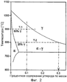
На фиг.2 изображена диаграмма фаз, представляющая различные кристаллические фазы, которые присутствуют при различных температурах, и в зависимости от содержания углерода конкретного сплава для углеродистой стали в соответствии с настоящим изобретением.2 is a phase diagram representing various crystalline phases that are present at different temperatures, and depending on the carbon content of a particular alloy for carbon steel in accordance with the present invention.
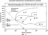
На фиг.3 показана диаграмма кинетического температурного преобразования по времени, демонстрирующая процедуры и условия способа второго этапа охлаждения в соответствии с настоящим изобретением для конкретной стали Fe/Si/C в соответствии с настоящим изобретением.FIG. 3 is a kinetic temperature transformation over time diagram showing the procedures and conditions of the method of the second cooling step in accordance with the present invention for a particular Fe / Si / C steel in accordance with the present invention.
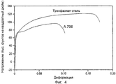
На фиг.4 представлен график зависимости деформации от напряжения для сравнения сплава в соответствии с настоящим изобретением и стали AISI Steel A706 известного уровня техники.4 is a graph of strain versus stress for comparing the alloy of the present invention and AISI Steel A706 of the prior art.
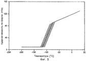
На фиг.5 показан график зависимости ударной вязкости по Шарпи от температуры для сплава в соответствии с настоящим изобретением, который имеет исключительную вязкость при низкой температуре.Figure 5 shows a graph of Charpy impact strength versus temperature for an alloy in accordance with the present invention that has exceptional low temperature viscosity.
Подробное описание изобретенияDETAILED DESCRIPTION OF THE INVENTION
Трехфазная кристаллическая структура в соответствии с настоящим изобретением таким образом, содержит два типа зерен - ферритные кристаллы и мартенситно-аустенитные зерна, сплавленные вместе в виде непрерывной массы, в которой мартенситно-аустенитные зерна содержат мартенситные пластины, имеющие смещенную решетчатую структуру. Размер отдельного зерна является не критичным и может изменяться в широких пределах. Для обеспечения наилучших результатов размер зерна, в общем, имеет диаметр (или другую соответственно характеризующую линейную размерность) в пределах диапазона от около 2 микрона до около 100 микрон или предпочтительно в диапазоне от около 5 микрон до около 30 микрон. В мартенситно-аустенитных зернах пластины мартенсита обычно имеют ширину от около 0,01 микрон до около 0,3 микрона (соседние пластины, разделенные тонкими аустенитными пленками), и предпочтительно от около 0,05 микрон до около 0,2 микрона. Количество фазы феррита по отношению к мартенситно-аустенитной фазе также может изменяться в широких пределах и является не критичным для целей настоящего изобретения. В большинстве случаев, однако, наилучшие результаты будут получены, когда мартенситно-аустенитные зерна составляют от около 5 до около 95% трехфазной кристаллической структуры, предпочтительно от около 15 до около 60% и наиболее предпочтительно от около 20 до около 40%, все проценты приведены по массе.The three-phase crystalline structure in accordance with the present invention thus contains two types of grains - ferrite crystals and martensitic-austenitic grains fused together as a continuous mass, in which martensitic-austenitic grains contain martensitic plates having a displaced lattice structure. The size of an individual grain is not critical and can vary widely. To provide the best results, the grain size generally has a diameter (or other linear dimension, respectively) within the range of about 2 microns to about 100 microns, or preferably in the range of about 5 microns to about 30 microns. In martensitic-austenitic grains, martensite plates typically have a width of from about 0.01 microns to about 0.3 microns (adjacent plates separated by thin austenitic films), and preferably from about 0.05 microns to about 0.2 microns. The amount of the ferrite phase with respect to the martensitic-austenitic phase can also vary within wide limits and is not critical for the purposes of the present invention. In most cases, however, the best results will be obtained when martensitic-austenitic grains comprise from about 5 to about 95% of the three-phase crystal structure, preferably from about 15 to about 60% and most preferably from about 20 to about 40%, all percentages are given by weight.
Содержание углерода в сплаве может также изменяться в пределах максимум 0,35%. В большинстве случаев наилучшие результаты будут получены при уровне углерода в диапазоне от около 0,01 до около 0,35%, предпочтительно от около 0,03 до около 0,3% и наиболее предпочтительно от около 0,05 до около 0,2%. Как указано выше, в составе сплава могут присутствовать карбидные или карбонитридные осадки, находящиеся внутри пластины, то есть осадки, расположенные, по большей части, скорее внутри мартенситных пластин, а не вдоль границ пластин, в то время как межфазные осадки (вдоль границ) предпочтительно исключаются. Другие легирующие элементы также присутствуют в определенных вариантах выполнения настоящего изобретения. В одном примере эти осадки состоят из кремния, который в предпочтительных вариантах выполнения составляет от около 0,1 до около 3%, и предпочтительно от около 1 до около 2,5%. Другой пример представляет хром, который может совсем отсутствовать (как в нехромистой Fe/Si/C стали) или в случае, когда он присутствует, его количество может находиться в диапазоне от около 1 до около 13%, предпочтительно, от около 6 до около 12% по массе, и более предпочтительно от около 8 до около 10%. Примеры других легирующих элементов, включенных в различные варианты выполнения настоящего изобретения, представляют собой марганец, никель, кобальт, алюминий и азот как по отдельности, так и в комбинациях. Микролегирующие элементы, такие как молибден, ниобий, титан и ванадий, также могут присутствовать в составе стали. Все процентные соотношения приведены по массе.The carbon content in the alloy may also vary within a maximum of 0.35%. In most cases, the best results will be obtained with a carbon level in the range of from about 0.01 to about 0.35%, preferably from about 0.03 to about 0.3%, and most preferably from about 0.05 to about 0.2% . As indicated above, carbide or carbonitride precipitates within the plate may be present in the composition of the alloy, i.e., precipitates located mainly within the martensitic plates rather than along the plate boundaries, while interfacial deposits (along the boundaries) are preferably are excluded. Other alloying elements are also present in certain embodiments of the present invention. In one example, these precipitates consist of silicon, which in preferred embodiments is from about 0.1 to about 3%, and preferably from about 1 to about 2.5%. Another example is chromium, which may be completely absent (as in non-chromium Fe / Si / C steel) or, when present, its amount may be in the range from about 1 to about 13%, preferably from about 6 to about 12 % by weight, and more preferably from about 8 to about 10%. Examples of other alloying elements included in various embodiments of the present invention are manganese, nickel, cobalt, aluminum and nitrogen, both individually and in combination. Microalloying elements, such as molybdenum, niobium, titanium and vanadium, may also be present in the steel. All percentages are by weight.
Предпочтительные трехфазные кристаллические структуры в соответствии с настоящим изобретением также, по существу, не содержат карбиды. Как указано выше, карбиды и другие осадки образуются в результате самоотпуска. Влияние, которое эти осадки оказывают на вязкость стали, зависит от морфологии осадков в микроструктуре стали. Если осадки располагаются по границам между фазами, в результате снижается вязкость и стойкость к коррозии. Осадки, расположенные внутри самих фаз, не ухудшают вязкость при условии, что размеры осадков в диаметре составляют приблизительно 500Å или меньше. Такие внутрифазные осадки могут фактически улучшать вязкость. В общем, однако, осадки могут снизить стойкость к коррозии. Таким образом, в предпочтительном варианте использования на практике настоящего изобретения самоотпуск может происходить при условии, что осадки не формируются на поверхностях раздела между разными кристаллическими фазами. Термин "по существу отсутствуют карбиды" используется здесь для указания, что, если какие-либо карбиды фактически присутствуют в составе стали, их количество настолько мало, что эти карбиды не оказывают отрицательного влияния на рабочие характеристики и, в частности, на характеристики коррозионной стойкости конечного сплава.Preferred three-phase crystalline structures in accordance with the present invention also essentially do not contain carbides. As indicated above, carbides and other precipitates are formed as a result of self-tempering. The effect that these precipitations have on the viscosity of steel depends on the morphology of the sediments in the microstructure of the steel. If precipitation is located between the phases, the viscosity and corrosion resistance are reduced as a result. Precipitation within the phases themselves does not impair viscosity, provided that the diameter of the precipitates is approximately 500 Å or less. Such intra-phase precipitates can actually improve viscosity. In general, however, precipitation can reduce corrosion resistance. Thus, in a preferred embodiment of the practice of the present invention, self-tempering can occur provided that no precipitation forms on the interfaces between different crystalline phases. The term "substantially no carbides" is used here to indicate that if any carbides are actually present in the steel, their quantity is so small that these carbides do not adversely affect the performance and, in particular, the corrosion resistance of the final alloy.
Трехфазные сплавы в соответствии с настоящим изобретением могут быть получены путем исходного комбинирования соответствующих компонентов, необходимых для формирования сплава требуемого состава, с последующей гомогенизацией (то есть "пропиткой") состава в течение достаточного периода времени и при достаточной температуре для получения однородной аустенитной структуры, все элементы и компоненты которой находятся в твердом растворе. Условия для такой гомогенизации будут очевидны для специалистов в данной области техники, и при этом обычно используют температуру в диапазоне от 1050 до 1200°С. В соответствии с практикой, хорошо известной в данной области техники, после пропитки часто следует прокатка с коэффициентом вытяжки 10% или больше, и во многих случаях с коэффициентом вытяжки от около 30 до около 60%. Это способствует диффузии легирующих элементов для формирования однородной кристаллической фазы аустенита.Three-phase alloys in accordance with the present invention can be obtained by initially combining the appropriate components necessary to form an alloy of the desired composition, followed by homogenization (ie, "impregnation") of the composition for a sufficient period of time and at a sufficient temperature to obtain a uniform austenitic structure, all elements and components of which are in solid solution. The conditions for such homogenization will be apparent to those skilled in the art, and typically a temperature in the range of 1050 to 1200 ° C. is used. In accordance with practice well known in the art, after impregnation often follows rolling with a drawing ratio of 10% or more, and in many cases with a drawing ratio from about 30 to about 60%. This promotes the diffusion of alloying elements to form a uniform crystalline austenite phase.
После формирования фазы аустенита состав сплава охлаждают до значения температуры в межкритической области, которая определяется как область, в которой фазы аустенита и феррита существуют одновременно в равновесии. В результате охлаждения, таким образом, часть аустенита рекристаллизуется в кристаллы феррита, и остальная ее часть остается в виде аустенитной фазы. Относительное количество каждой из этих двух фаз при равновесии изменяется в зависимости от температуры охлаждения состава на этом этапе, а также от уровня легирующих элементов. Распределение углерода между двумя фазами (вновь при равновесном состоянии) также изменяется в зависимости от температуры. Как указано выше, относительные количества двух фаз являются не критичными для целей настоящего изобретения и могут изменяться в определенных предпочтительных диапазонах. Что касается температуры охлаждения аустенита для получения двухфазной феррито-аустенитной структуры, предпочтительный диапазон температуры выбирают от около 750 до около 950°С и более предпочтительный диапазон температур составляет от около 775 до около 900°С в зависимости от состава сплава.After the formation of the austenite phase, the alloy composition is cooled to a temperature in the intercritical region, which is defined as the region in which the phases of austenite and ferrite exist simultaneously in equilibrium. As a result of cooling, thus, part of the austenite is recrystallized into ferrite crystals, and the rest of it remains as an austenitic phase. The relative amount of each of these two phases at equilibrium varies depending on the cooling temperature of the composition at this stage, as well as on the level of alloying elements. The carbon distribution between the two phases (again at equilibrium) also varies with temperature. As indicated above, the relative amounts of the two phases are not critical for the purposes of the present invention and may vary in certain preferred ranges. Regarding the cooling temperature of austenite to obtain a biphasic ferritic-austenitic structure, a preferred temperature range is selected from about 750 to about 950 ° C. and a more preferred temperature range is from about 775 to about 900 ° C. depending on the composition of the alloy.
После формирования двухфазных структур феррита и аустенита (то есть после достижения равновесного состояния при выбранной температуре в межкритической фазе) сплав быстро закаливают путем охлаждения в диапазоне фазового превращения мартенсита для преобразования зерен аустенита в смещенную решетчатую микроструктуру. Скорость охлаждения выбирают достаточно высокой для, по существу, предотвращения каких-либо изменений фазы феррита. Однако, кроме того, в предпочтительных вариантах выполнения настоящего изобретения скорость охлаждения выбирают достаточно высокой для исключения формирования бейнита и перлита, а также нитридных и карбонитридных осадков в зависимости от состава сплава, в также формирование любых осадков вдоль границ фаз. Термины "межфазное осаждение" и "межфазные осадки" используют здесь для обозначения осаждения вдоль границ фаз, и он означает формирование небольших количеств осадков различных соединений в местах между фазами мартенсита и аустенита, то есть между пластинами и тонкими пленками, разделяющими пластины. Термин "межфазные осадки" не означает сами пленки аустенита. Формирование осадков различных типов, включая бейнитные, перлитные, нитридные и карбонитридные осадки, в также межфазные осадки, в общем, называется здесь "самоотпуском". Минимальная скорость охлаждения, требуемая для исключения самоотпуска, известна из диаграммы преобразования - температуры - времени для сплава. По вертикальной оси диаграммы представлена температура, а по горизонтальной оси представлено время, и кривые на диаграмме указывают области, где каждая фаза существует либо самостоятельно или в комбинации с другой фазой (фазами). Типичная такая диаграмма представлена в американском патенте №6273968 В1, автора Thomas, ссылка на который приведена выше, и такая диаграмма изображена здесь на фиг.3, описанной ниже. На таких диаграммах минимальная скорость охлаждения представлена наклонной линией снижения температуры в зависимости от времени, которая касается с левой стороны С-образной кривой. Область справа от кривой показывает наличие карбидов и приемлемые скорости охлаждения, поэтому представлены линиями, которые остаются слева от кривой, самая малая из которых имеет наименьший наклон и примыкает к кривой.After the formation of two-phase structures of ferrite and austenite (that is, after reaching an equilibrium state at a selected temperature in the intercritical phase), the alloy is rapidly quenched by cooling in the range of the martensite phase transformation to convert austenite grains to a displaced lattice microstructure. The cooling rate is chosen high enough to essentially prevent any changes in the ferrite phase. However, in addition, in preferred embodiments of the present invention, the cooling rate is chosen high enough to prevent the formation of bainite and perlite, as well as nitride and carbonitride precipitates depending on the alloy composition, as well as the formation of any precipitation along the phase boundaries. The terms "interfacial deposition" and "interfacial precipitation" are used here to denote deposition along the phase boundaries, and it means the formation of small amounts of precipitation of various compounds in the places between the phases of martensite and austenite, that is, between the plates and thin films separating the plates. The term "interfacial precipitation" does not mean the austenite films themselves. The formation of precipitation of various types, including bainitic, pearlitic, nitride and carbonitride precipitates, as well as interphase precipitations, in general, is called here "self-release". The minimum cooling rate required to eliminate self-tempering is known from the conversion — temperature — time diagram for the alloy. The temperature is represented on the vertical axis of the diagram, and time is represented on the horizontal axis, and the curves on the diagram indicate the areas where each phase exists either independently or in combination with another phase (s). A typical such diagram is presented in U.S. Patent No. 6,273,968 B1 to Thomas, referenced above, and such a diagram is shown here in FIG. 3, described below. In such diagrams, the minimum cooling rate is represented by an inclined line of temperature reduction depending on time, which touches the C-shaped curve on the left side. The area to the right of the curve shows the presence of carbides and acceptable cooling rates, therefore, are represented by lines that remain to the left of the curve, the smallest of which has the smallest slope and is adjacent to the curve.
В зависимости от состава сплава скорость охлаждения, достаточно большая для удовлетворения этого требования, может иметь такое значение, для которого требуется охлаждение водой, или скорость, которая может быть получена при охлаждении воздухом. В общем, если уровни определенных легирующих элементов в составе сплава, которые можно охлаждать воздухом с обеспечением достаточно высокой скорости охлаждения, снижаются, необходимо повышать уровни других легирующих элементов для поддержания возможности охлаждения воздухом. Например, снижение содержания одного или нескольких таких легирующих элементов, как углерод, хром или кремний, может быть компенсировано повышением уровня такого элемента, как марганец.Depending on the composition of the alloy, a cooling rate large enough to satisfy this requirement may have a value that requires cooling with water, or a speed that can be obtained by cooling with air. In general, if the levels of certain alloying elements in the alloy, which can be cooled by air with a sufficiently high cooling rate, decrease, it is necessary to raise the levels of other alloying elements to maintain the possibility of cooling by air. For example, a decrease in the content of one or more alloying elements such as carbon, chromium or silicon can be compensated by an increase in the level of an element such as manganese.
Предпочтительные составы сплава для целей настоящего изобретения представляют собой сплавы, которые содержат от около 0,05 до около 0,1% углерода, от около 0,3 до около 5% никеля и около 2% кремния, все процентные соотношения приведены по массе, причем остальное составляет железо. Никель может быть заменен марганцем при концентрации, по меньшей мере, около 0,5%, предпочтительно 1-2% (по массе) или могут присутствовать оба эти элемента. Предпочтительный способ закаливания представляет собой охлаждение водой. Предпочтительные составы сплавов представляют собой также сплавы, которые имеют начальную температуру преобразования мартенсита около 300°С или выше.Preferred alloy compositions for the purposes of the present invention are alloys that contain from about 0.05 to about 0.1% carbon, from about 0.3 to about 5% nickel and about 2% silicon, all percentages are by weight, moreover the rest is iron. Nickel can be replaced with manganese at a concentration of at least about 0.5%, preferably 1-2% (by weight), or both of these elements may be present. A preferred quenching method is water cooling. Preferred alloy compositions are also alloys that have an initial martensite conversion temperature of about 300 ° C. or higher.
Приемы и условия обработки, приведенные в американских патентах, ссылки на которые сделаны выше, в частности, тепловая обработка, рафинирование зерен, ковка в линии и использование прокатных сплавов для формирования круглых, плоских и других форм продуктов можно использовать на практике в соответствии с настоящим изобретением для нагрева состава сплава до фазы аустенита, охлаждения сплава от фазы аустенита до межкритической фазы и последующего охлаждения через область фазового превращения мартенсита. Прокатку выполняют управляемым образом с использованием одного или нескольких этапов в ходе приемов аустенизации и первого этапа охлаждения, например, для облегчения диффузии легирующих элементов, для формирования гомогенной аустенитной кристаллической фазы и затем для деформирования зерен кристаллов и накопления энергии деформации в зернах, в то время как при охлаждении на втором этапе прокатку можно использовать для направления вновь формируемой мартенситной фазы с получением смещенной решетчатой структуры мартенсита, разделенной тонкими пленками остаточного аустенита. Коэффициент вытяжки при прокатке может изменяться, и его значение будет очевидно для специалистов в данной области техники. В мартенсито-аустенитных смещенных решетках кристаллов пленки остаточного аустенита будут составлять от около 0,5% до около 15 об.% микроструктуры, предпочтительно от около 3% до около 10%, и наиболее предпочтительно максимум около 5%. Пропорция аустенита по отношению к общей трехфазной микроструктуре может составлять максимум около 5%. Собственно ширина одиночной остаточной аустенитной пленки, предпочтительно, составляет в диапазоне от около 50Å до около 250Å, и предпочтительно, составляет около 100Å. Пропорция аустенита по отношению к общей трехфазной микроструктуре, в общем, будет составлять максимум около 5%.The methods and processing conditions described in US patents, the references to which are made above, in particular, heat treatment, grain refining, forging in line and the use of rolled alloys to form round, flat and other shapes of products, can be used in practice in accordance with the present invention for heating the alloy composition to the austenite phase, cooling the alloy from the austenite phase to the intercritical phase and subsequent cooling through the region of the martensite phase transformation. Rolling is performed in a controlled manner using one or more stages during austenitization and the first cooling stage, for example, to facilitate the diffusion of alloying elements, to form a homogeneous austenitic crystalline phase, and then to deform the crystal grains and accumulate the strain energy in the grains, during cooling in the second stage, rolling can be used to direct the newly formed martensitic phase to obtain a displaced lattice structure of martensite, divided th thin films of retained austenite. The coefficient of drawing during rolling can vary, and its value will be obvious to specialists in this field of technology. In martensite-austenitic biased crystal lattices, films of residual austenite will comprise from about 0.5% to about 15 vol.% Microstructure, preferably from about 3% to about 10%, and most preferably a maximum of about 5%. The proportion of austenite with respect to the general three-phase microstructure can be a maximum of about 5%. The actual width of a single residual austenitic film is preferably in the range of from about 50Å to about 250Å, and preferably is about 100Å. The proportion of austenite relative to the total three-phase microstructure will generally be a maximum of about 5%.
На фиг.1 представлен эскиз трехфазной кристаллической структуры в соответствии с настоящим изобретением. Эта структура включает кристаллы 11 феррита, сплавленные с мартенсито-аустенитными зернами 12, и каждое из мартенсито-аустенитных зерен 12 имеет смещенную решетчатую структуру с, по существу, параллельными решетками 13, состоящими из зерен кристаллов мартенситной фазы, причем эти решетки разделены тонкими пленками 14 из остаточной аустенитной фазы.Figure 1 presents a sketch of a three-phase crystalline structure in accordance with the present invention. This structure includes ferrite crystals 11 fused with martensite-austenitic grains 12, and each of the martensite-austenitic grains 12 has a displaced lattice structure with essentially parallel lattices 13, consisting of grains of crystals of the martensitic phase, and these lattices are separated by thin films 14 from the residual austenitic phase.
На фиг.2 показана диаграмма фаз для класса углеродистых сталей с обозначением преобразований, которые происходят во время этапов охлаждения и влияния различных концентраций углерода. На данной конкретной диаграмме фаз представлены углеродистые стали, которые содержат 2% кремния. Область справа от верхней кривой обозначена буквой "γ", которая представляет аустенитную фазу; все другие области содержат обозначение "α", которое представляет фазу феррита. На этапе аустенизации сплав нагревают до области полной γ-фазы в правом верхнем углу. Вертикальная пунктирная линия на уровне 0,1% углерода обозначает фазы, которые образуются при охлаждении сплава для стали с содержанием 0,1% углерода (содержащего 2% кремния) из аустенитной фазы. Если охлаждение останавливают на температуре 900°С ("Т-1"), значения концентрации углерода в этих двух фазах будут такими, как обозначено пересечением линий Т-1 с двумя кривыми. В случае, показанном на фиг.2, содержание углерода двух фаз при охлаждении до Т-1 приблизительно составляет 0,001% С в фазе феррита и 0,14% в фазе аустенита. Пропорция фаз также устанавливается по выбранной температуре. Хотя на данной диаграмме фаз это не видно, пропорции могут быть определены специалистами в данной области техники. В случае, показанном на фиг.2, достигаемая пропорция при Т-1 составляет 60% аустенита и 40% феррита. Если сталь охлаждают до 800°С ("Т-2"), концентрация углерода в двух фазах будет такой, как показано пересечением линий Т-2 с двумя кривыми, которые отличаются от значений, соответствующих 900°С, и пропорция фаз также будет отличаться. В этом случае уровни углерода в двух фазах составят приблизительно 0,03% в фазе феррита и 0,3% в фазе аустенита. Относительные количества двух фаз составят приблизительно 25% аустенита и 75% феррита. Таким образом, пропорцию выбирают путем выбора температуры, до которой происходит охлаждение на первом этапе, и путем поддержания температуры Ms аустенита выше 300°С.Figure 2 shows a phase diagram for a class of carbon steels with the designations of the transformations that occur during the stages of cooling and the influence of different concentrations of carbon. This particular phase diagram shows carbon steels that contain 2% silicon. The area to the right of the upper curve is indicated by the letter "γ", which represents the austenitic phase; all other areas contain the designation "α", which represents the phase of ferrite. At the austenitization stage, the alloy is heated to the region of the complete γ phase in the upper right corner. The vertical dashed line at 0.1% carbon indicates the phases that form when the alloy is cooled for steel with 0.1% carbon (containing 2% silicon) from the austenitic phase. If cooling is stopped at a temperature of 900 ° C ("T-1"), the carbon concentration values in these two phases will be as indicated by the intersection of the T-1 lines with two curves. In the case shown in FIG. 2, the carbon content of the two phases upon cooling to T-1 is approximately 0.001% C in the ferrite phase and 0.14% in the austenite phase. The proportion of phases is also set by the selected temperature. Although this is not visible in this phase diagram, the proportions can be determined by those skilled in the art. In the case shown in figure 2, the achieved proportion at T-1 is 60% austenite and 40% ferrite. If the steel is cooled to 800 ° C ("T-2"), the carbon concentration in the two phases will be as shown by the intersection of the T-2 lines with two curves that differ from the values corresponding to 900 ° C, and the phase proportion will also differ . In this case, the carbon levels in the two phases will be approximately 0.03% in the ferrite phase and 0.3% in the austenite phase. The relative amounts of the two phases will be approximately 25% austenite and 75% ferrite. Thus, the proportion is selected by selecting the temperature to which cooling occurs in the first step, and by maintaining the austenite temperature M s above 300 ° C.
После выполнения охлаждения первого этапа сталь подвергают управляемой прокатке с использованием способов, хорошо известных в данной области техники, с управлением размера зерен, а также для деформирования и профилирования изделий из стали для конечного использования.After performing the cooling of the first stage, the steel is subjected to controlled rolling using methods well known in the art, with grain size control, as well as for deformation and profiling of steel products for end use.
Затем выполняют охлаждение второго этапа, в результате которого формируется мартенситная фаза в компоновке смещенных решеток. Как указано выше, это выполняют с достаточно высокой скоростью для предотвращения формирования как бейнита, так и перлита, а также формирования каких-либо межфазных осадков. На фиг.3 показана диаграмма кинетических температурных преобразований по времени, представляющая второй этап охлаждения для сплава, содержащего 0,079% С, 0,57% Mn и 1,902% Si. На схеме использованы следующие обозначения:Then, the second stage is cooled, as a result of which a martensitic phase is formed in the arrangement of the displaced lattices. As indicated above, this is performed at a sufficiently high speed to prevent the formation of both bainite and perlite, as well as the formation of any interfacial deposits. Figure 3 shows a diagram of kinetic temperature transformations over time, representing the second cooling step for an alloy containing 0.079% C, 0.57% Mn and 1.902% Si. The following notation is used in the diagram:
"А": аустенитA: austenite
"М": мартенситM: Martensite
"F": феррит"F": ferrite
"В":бейнит"B": bainite
"UB": верхний бейнит"UB": upper bainite
"LB": нижний бейнит"LB": lower bainite
"Р": перлит"P": perlite
"Ms": начальная температура мартенсита (420°С)"M s ": initial temperature of martensite (420 ° C)
"Mf": конечная температура мартенсита (200°С)"M f ": final martensite temperature (200 ° C)
Наклонной пунктирной линией на фиг.3 обозначена наименьшая скорость охлаждения, при которой предотвращается формирование байнита или перлита и межфазное осаждение вообще, и поэтому может быть использована эта скорость или любая скорость охлаждения, которая представлена более крутыми линиями.The oblique dashed line in FIG. 3 indicates the lowest cooling rate at which the formation of bainite or perlite and interfacial deposition are generally prevented, and therefore this rate or any cooling rate that is represented by steeper lines can be used.
На фиг.4 изображен график зависимости напряжения от деформации для сравнения сплава для углеродистой стали с трехфазной кристаллической структурой в соответствии с настоящим изобретением, в котором мартенсито-аустенитная фаза составляет 40% всей микроструктуры, и межрешетчатый аустенит составляет 2% всей микроструктуры у обычного сплава стали AISI A706. Отношение предела прочности на разрыв к пределу текучести больше чем 1,5, и на графике показано преимущество сплава в соответствии с настоящим изобретением.Figure 4 shows a graph of stress versus strain for comparing an alloy for carbon steel with a three-phase crystalline structure in accordance with the present invention, in which the martensite-austenitic phase accounts for 40% of the total microstructure and the interlattice austenite makes up 2% of the total microstructure of a conventional steel alloy AISI A706. The ratio of tensile strength to yield strength is greater than 1.5, and the graph shows the advantage of the alloy in accordance with the present invention.
На фиг.5 показан график зависимости ударной вязкости по Шарпи от температуры для того же сплава углеродистой стали в соответствии с настоящим изобретением, свойства которого представлены на фиг.4.Figure 5 shows a graph of Charpy impact strength versus temperature for the same carbon steel alloy in accordance with the present invention, the properties of which are presented in figure 4.
Сплавы для стали в соответствии с настоящим изобретением являются в особенности пригодными для изделий, в которых требуется обеспечить высокий предел прочности на разрыв, в особенности, используемых в соленой/морской среде воздействия.The alloys for steel in accordance with the present invention are particularly suitable for products in which a high tensile strength is required to be achieved, especially those used in a salt / marine exposure environment.
Приведенное выше описание, в основном, предназначено для иллюстрации. Дополнительные модификации и изменения различных параметров состава сплава, процесса и условий обработки могут быть выполнены так, что они будут воплощать основы и новые концепции настоящего изобретения. Такие условия будут очевидны для специалистов в данной области техники и будут включены в объем настоящего изобретения.The above description is mainly for illustration. Additional modifications and changes to various parameters of the alloy composition, process and processing conditions can be performed so that they embody the basics and new concepts of the present invention. Such conditions will be apparent to those skilled in the art and will be included within the scope of the present invention.
Claims (10)
Applications Claiming Priority (2)
| Application Number | Priority Date | Filing Date | Title |
|---|---|---|---|
| US10/017,847 | 2001-12-14 | ||
| US10/017,847 US6746548B2 (en) | 2001-12-14 | 2001-12-14 | Triple-phase nano-composite steels |
Publications (2)
| Publication Number | Publication Date |
|---|---|
| RU2004121460A RU2004121460A (en) | 2005-06-10 |
| RU2293769C2 true RU2293769C2 (en) | 2007-02-20 |
Family
ID=21784867
Family Applications (1)
| Application Number | Title | Priority Date | Filing Date |
|---|---|---|---|
| RU2004121460/02A RU2293769C2 (en) | 2001-12-14 | 2002-12-12 | Three-phase nanocomposite steels |
Country Status (21)
| Country | Link |
|---|---|
| US (2) | US6746548B2 (en) |
| EP (1) | EP1461467B1 (en) |
| JP (2) | JP4994572B2 (en) |
| KR (1) | KR100860292B1 (en) |
| CN (1) | CN100406601C (en) |
| AR (1) | AR037829A1 (en) |
| AT (1) | ATE405683T1 (en) |
| AU (1) | AU2002361700B2 (en) |
| BR (1) | BR0214966B1 (en) |
| CA (1) | CA2470388C (en) |
| DE (1) | DE60228493D1 (en) |
| ES (1) | ES2310620T3 (en) |
| HK (1) | HK1065342A1 (en) |
| MX (1) | MXPA04005743A (en) |
| NO (1) | NO340613B1 (en) |
| NZ (1) | NZ533658A (en) |
| PT (1) | PT1461467E (en) |
| RU (1) | RU2293769C2 (en) |
| UA (1) | UA76012C2 (en) |
| WO (1) | WO2003052153A1 (en) |
| ZA (1) | ZA200404736B (en) |
Cited By (1)
| Publication number | Priority date | Publication date | Assignee | Title |
|---|---|---|---|---|
| WO2013188100A1 (en) * | 2012-05-25 | 2013-12-19 | Cola Gary M | Microtreatment and microstructure of carbide containing iron-based alloy |
Families Citing this family (20)
| Publication number | Priority date | Publication date | Assignee | Title |
|---|---|---|---|---|
| US7235212B2 (en) * | 2001-02-09 | 2007-06-26 | Ques Tek Innovations, Llc | Nanocarbide precipitation strengthened ultrahigh strength, corrosion resistant, structural steels and method of making said steels |
| JP2003129190A (en) * | 2001-10-19 | 2003-05-08 | Sumitomo Metal Ind Ltd | Martensitic stainless steel and manufacturing method therefor |
| US20040149362A1 (en) * | 2002-11-19 | 2004-08-05 | Mmfx Technologies Corporation, A Corporation Of The State Of California | Cold-worked steels with packet-lath martensite/austenite microstructure |
| US20070228729A1 (en) * | 2003-03-06 | 2007-10-04 | Grimmett Harold M | Tubular goods with threaded integral joint connections |
| US7169239B2 (en) * | 2003-05-16 | 2007-01-30 | Lone Star Steel Company, L.P. | Solid expandable tubular members formed from very low carbon steel and method |
| US20050247382A1 (en) * | 2004-05-06 | 2005-11-10 | Sippola Pertti J | Process for producing a new high-strength dual-phase steel product from lightly alloyed steel |
| US7214278B2 (en) * | 2004-12-29 | 2007-05-08 | Mmfx Technologies Corporation | High-strength four-phase steel alloys |
| JP5868704B2 (en) * | 2008-07-24 | 2016-02-24 | シーアールエス ホールディングス, インコーポレイテッドCrs Holdings, Incorporated | High strength and high toughness steel alloy |
| DE102008051992B4 (en) * | 2008-10-16 | 2011-03-24 | Benteler Automobiltechnik Gmbh | Method for producing a workpiece, workpiece and use of a workpiece |
| CN101671772B (en) * | 2009-09-29 | 2011-05-04 | 燕山大学 | Method for preparing ultra-fine grained ferrite and nano-carbide low-carbon steel plate |
| US20110236696A1 (en) * | 2010-03-25 | 2011-09-29 | Winky Lai | High strength rebar |
| RU2503726C2 (en) * | 2011-05-04 | 2014-01-10 | Государственное образовательное учреждение высшего профессионального образования "Брянская государственная инженерно-технологическая академия" | Method of steel complex heat treatment |
| FI20115702L (en) * | 2011-07-01 | 2013-01-02 | Rautaruukki Oyj | METHOD FOR PRODUCING HIGH-STRENGTH STRUCTURAL STEEL AND HIGH-STRENGTH STRUCTURAL STEEL |
| US8518195B2 (en) * | 2012-01-20 | 2013-08-27 | GM Global Technology Operations LLC | Heat treatment for producing steel sheet with high strength and ductility |
| US8978430B2 (en) | 2013-03-13 | 2015-03-17 | Commercial Metals Company | System and method for stainless steel cladding of carbon steel pieces |
| CN103589954B (en) * | 2013-11-29 | 2015-07-15 | 东北大学 | Hot rolling steel plate with characteristic of multiple grades in one steel, and manufacturing method thereof |
| WO2016001706A1 (en) | 2014-07-03 | 2016-01-07 | Arcelormittal | Method for producing a high strength steel sheet having improved strength and formability and obtained sheet |
| WO2016001710A1 (en) * | 2014-07-03 | 2016-01-07 | Arcelormittal | Method for producing a high strength coated steel having improved strength and ductility and obtained sheet |
| WO2016001702A1 (en) | 2014-07-03 | 2016-01-07 | Arcelormittal | Method for producing a high strength coated steel sheet having improved strength, ductility and formability |
| WO2016001700A1 (en) | 2014-07-03 | 2016-01-07 | Arcelormittal | Method for producing a high strength steel sheet having improved strength, ductility and formability |
Family Cites Families (11)
| Publication number | Priority date | Publication date | Assignee | Title |
|---|---|---|---|---|
| US4170499A (en) * | 1977-08-24 | 1979-10-09 | The Regents Of The University Of California | Method of making high strength, tough alloy steel |
| US4170497A (en) * | 1977-08-24 | 1979-10-09 | The Regents Of The University Of California | High strength, tough alloy steel |
| JPS60190552A (en) * | 1984-03-12 | 1985-09-28 | Sumitomo Metal Ind Ltd | Sintered stainless steel and its manufacture |
| US4619714A (en) * | 1984-08-06 | 1986-10-28 | The Regents Of The University Of California | Controlled rolling process for dual phase steels and application to rod, wire, sheet and other shapes |
| US4671827A (en) * | 1985-10-11 | 1987-06-09 | Advanced Materials And Design Corp. | Method of forming high-strength, tough, corrosion-resistant steel |
| JP2588420B2 (en) * | 1988-04-11 | 1997-03-05 | 日新製鋼株式会社 | Method for producing ultra-high strength steel with good ductility |
| US5545270A (en) * | 1994-12-06 | 1996-08-13 | Exxon Research And Engineering Company | Method of producing high strength dual phase steel plate with superior toughness and weldability |
| US6159312A (en) | 1997-12-19 | 2000-12-12 | Exxonmobil Upstream Research Company | Ultra-high strength triple phase steels with excellent cryogenic temperature toughness |
| DZ2531A1 (en) * | 1997-12-19 | 2003-02-08 | Exxon Production Research Co | Process for the preparation of a double phase steel sheet, this sheet and process for strengthening the resistance to crack propagation. |
| JPH11350064A (en) | 1998-06-08 | 1999-12-21 | Kobe Steel Ltd | High strength steel sheet excellent in shape fixability and impact resistance and its production |
| DK1218552T3 (en) * | 1999-07-12 | 2009-11-30 | Mmfx Steel Corp Of America | Low carbon steel with projected mechanical corrosion properties |
-
2001
- 2001-12-14 US US10/017,847 patent/US6746548B2/en not_active Expired - Lifetime
-
2002
- 2002-12-12 AT AT02797338T patent/ATE405683T1/en not_active IP Right Cessation
- 2002-12-12 KR KR1020047009225A patent/KR100860292B1/en not_active IP Right Cessation
- 2002-12-12 WO PCT/US2002/040126 patent/WO2003052153A1/en active IP Right Grant
- 2002-12-12 NZ NZ533658A patent/NZ533658A/en not_active IP Right Cessation
- 2002-12-12 AU AU2002361700A patent/AU2002361700B2/en not_active Ceased
- 2002-12-12 CN CNB028279646A patent/CN100406601C/en not_active Expired - Fee Related
- 2002-12-12 PT PT02797338T patent/PT1461467E/en unknown
- 2002-12-12 RU RU2004121460/02A patent/RU2293769C2/en not_active IP Right Cessation
- 2002-12-12 UA UA20040705664A patent/UA76012C2/en unknown
- 2002-12-12 CA CA2470388A patent/CA2470388C/en not_active Expired - Lifetime
- 2002-12-12 EP EP02797338A patent/EP1461467B1/en not_active Expired - Lifetime
- 2002-12-12 BR BRPI0214966-4A patent/BR0214966B1/en not_active IP Right Cessation
- 2002-12-12 MX MXPA04005743A patent/MXPA04005743A/en active IP Right Grant
- 2002-12-12 ES ES02797338T patent/ES2310620T3/en not_active Expired - Lifetime
- 2002-12-12 DE DE60228493T patent/DE60228493D1/en not_active Expired - Lifetime
- 2002-12-12 JP JP2003553020A patent/JP4994572B2/en not_active Expired - Fee Related
- 2002-12-13 AR ARP020104848A patent/AR037829A1/en not_active Application Discontinuation
-
2003
- 2003-03-31 US US10/405,209 patent/US6827797B2/en not_active Expired - Lifetime
-
2004
- 2004-06-15 ZA ZA200404736A patent/ZA200404736B/en unknown
- 2004-07-13 NO NO20042995A patent/NO340613B1/en not_active IP Right Cessation
- 2004-10-20 HK HK04108180A patent/HK1065342A1/en not_active IP Right Cessation
-
2010
- 2010-10-14 JP JP2010232026A patent/JP2011052324A/en active Pending
Cited By (1)
| Publication number | Priority date | Publication date | Assignee | Title |
|---|---|---|---|---|
| WO2013188100A1 (en) * | 2012-05-25 | 2013-12-19 | Cola Gary M | Microtreatment and microstructure of carbide containing iron-based alloy |
Also Published As
Similar Documents
| Publication | Publication Date | Title |
|---|---|---|
| RU2293769C2 (en) | Three-phase nanocomposite steels | |
| RU2293768C2 (en) | Nanocomposite martensite steels | |
| WO2019009410A1 (en) | Hot-rolled steel sheet and method for manufacturing same | |
| JP4810153B2 (en) | Low carbon steel with excellent mechanical and corrosion properties | |
| US20070012386A1 (en) | High strength steel plate and method for manufacturing the same | |
| JP2003138345A (en) | High strength and high ductility steel and steel sheet having excellent local ductility, and method of producing the steel sheet | |
| EP3392367B1 (en) | High-strength steel material having excellent low-temperature strain aging impact properties and method for manufacturing same | |
| US4397698A (en) | Method of making as-hot-rolled plate | |
| JP6684905B2 (en) | High-strength cold-rolled steel sheet excellent in shear workability and method for producing the same | |
| JP4677854B2 (en) | Induction hardening carbon steel and machine structural parts | |
| JP3945373B2 (en) | Method for producing cold-rolled steel sheet with fine grain structure and excellent fatigue characteristics | |
| JP2002256376A (en) | Steel sheet having low deterioration in toughness caused by strain aging | |
| JPH0790477A (en) | Wear resistant steel excellent in workability and weldability | |
| JP2002088440A (en) | High tensile strength steel having high uniform elongation | |
| JPS60181229A (en) | Production of low-yield ratio high-tension thick steel plate | |
| JPH06340922A (en) | Production of low yield ratio high tensile strength steel pipe | |
| WO2021255855A1 (en) | Steel sheet | |
| JP2004218066A (en) | Steel sheet with composite structure having excellent fatigue property, and production method therefor | |
| JP3303672B2 (en) | High-strength steel excellent in hot-dip galvanizing crack resistance and method for producing the same | |
| Edmonds | Designing with microalloyed and interstitial free steels | |
| JPH08225853A (en) | Production of hot rolled steel sheet for electric resistance welded tube excellent in wear resistance |
Legal Events
| Date | Code | Title | Description |
|---|---|---|---|
| MM4A | The patent is invalid due to non-payment of fees |
Effective date: 20181213 |