RU2291426C2 - Method for determining disappearance point of oil product crystals and apparatus for performing the same - Google Patents
Method for determining disappearance point of oil product crystals and apparatus for performing the same Download PDFInfo
- Publication number
- RU2291426C2 RU2291426C2 RU2005116024/28A RU2005116024A RU2291426C2 RU 2291426 C2 RU2291426 C2 RU 2291426C2 RU 2005116024/28 A RU2005116024/28 A RU 2005116024/28A RU 2005116024 A RU2005116024 A RU 2005116024A RU 2291426 C2 RU2291426 C2 RU 2291426C2
- Authority
- RU
- Russia
- Prior art keywords
- optical receiver
- temperature
- laser emitter
- measuring cell
- crystals
- Prior art date
Links
- 239000013078 crystal Substances 0.000 title claims abstract description 45
- 230000008034 disappearance Effects 0.000 title claims abstract description 31
- 238000000034 method Methods 0.000 title claims abstract description 14
- 230000003287 optical effect Effects 0.000 claims abstract description 76
- 238000001816 cooling Methods 0.000 claims description 22
- 239000003350 kerosene Substances 0.000 claims description 15
- 238000001514 detection method Methods 0.000 claims description 9
- 239000003209 petroleum derivative Substances 0.000 claims description 5
- 239000013307 optical fiber Substances 0.000 claims description 4
- 238000002425 crystallisation Methods 0.000 claims description 3
- 230000008025 crystallization Effects 0.000 claims description 3
- 229910052751 metal Inorganic materials 0.000 claims description 3
- 239000002184 metal Substances 0.000 claims description 3
- 229910052782 aluminium Inorganic materials 0.000 claims description 2
- XAGFODPZIPBFFR-UHFFFAOYSA-N aluminium Chemical compound [Al] XAGFODPZIPBFFR-UHFFFAOYSA-N 0.000 claims description 2
- 239000003208 petroleum Substances 0.000 claims description 2
- 238000012546 transfer Methods 0.000 claims description 2
- 239000012141 concentrate Substances 0.000 claims 1
- 238000005259 measurement Methods 0.000 abstract description 2
- 230000000694 effects Effects 0.000 abstract 1
- 239000000126 substance Substances 0.000 abstract 1
- 210000004027 cell Anatomy 0.000 description 25
- 238000012360 testing method Methods 0.000 description 6
- 238000010586 diagram Methods 0.000 description 4
- 239000011521 glass Substances 0.000 description 4
- 230000007423 decrease Effects 0.000 description 3
- 230000035945 sensitivity Effects 0.000 description 3
- 238000013461 design Methods 0.000 description 2
- 239000000835 fiber Substances 0.000 description 2
- 239000012535 impurity Substances 0.000 description 2
- 238000009434 installation Methods 0.000 description 2
- 230000010287 polarization Effects 0.000 description 2
- 238000004458 analytical method Methods 0.000 description 1
- 238000000149 argon plasma sintering Methods 0.000 description 1
- 238000011109 contamination Methods 0.000 description 1
- 239000002283 diesel fuel Substances 0.000 description 1
- 239000000446 fuel Substances 0.000 description 1
- 238000012797 qualification Methods 0.000 description 1
- 239000007787 solid Substances 0.000 description 1
Images

Classifications
-
- G—PHYSICS
- G01—MEASURING; TESTING
- G01N—INVESTIGATING OR ANALYSING MATERIALS BY DETERMINING THEIR CHEMICAL OR PHYSICAL PROPERTIES
- G01N33/00—Investigating or analysing materials by specific methods not covered by groups G01N1/00 - G01N31/00
- G01N33/26—Oils; Viscous liquids; Paints; Inks
- G01N33/28—Oils, i.e. hydrocarbon liquids
- G01N33/2811—Oils, i.e. hydrocarbon liquids by measuring cloud point or pour point of oils
-
- G—PHYSICS
- G01—MEASURING; TESTING
- G01N—INVESTIGATING OR ANALYSING MATERIALS BY DETERMINING THEIR CHEMICAL OR PHYSICAL PROPERTIES
- G01N25/00—Investigating or analyzing materials by the use of thermal means
- G01N25/02—Investigating or analyzing materials by the use of thermal means by investigating changes of state or changes of phase; by investigating sintering
- G01N25/04—Investigating or analyzing materials by the use of thermal means by investigating changes of state or changes of phase; by investigating sintering of melting point; of freezing point; of softening point
Landscapes
- Chemical & Material Sciences (AREA)
- Health & Medical Sciences (AREA)
- Life Sciences & Earth Sciences (AREA)
- Immunology (AREA)
- Engineering & Computer Science (AREA)
- Biochemistry (AREA)
- General Health & Medical Sciences (AREA)
- General Physics & Mathematics (AREA)
- Physics & Mathematics (AREA)
- Pathology (AREA)
- Analytical Chemistry (AREA)
- Chemical Kinetics & Catalysis (AREA)
- General Chemical & Material Sciences (AREA)
- Oil, Petroleum & Natural Gas (AREA)
- Food Science & Technology (AREA)
- Medicinal Chemistry (AREA)
- Investigating Or Analysing Materials By Optical Means (AREA)
- Investigating Or Analyzing Materials Using Thermal Means (AREA)
Abstract
Description
Область техникиTechnical field
Настоящее изобретение относится к способу определения точки исчезновения кристаллов нефтепродуктов, в частности авиационного керосина, в диапазоне температур от -5 до -120°C.The present invention relates to a method for determining the disappearance point of crystals of petroleum products, in particular aviation kerosene, in the temperature range from -5 to -120 ° C.
Предшествующий уровень техникиState of the art
Точка исчезновения кристаллов определяется как температура исчезновения последних кристаллов в предварительно кристаллизованном образце при постепенном повышении температуры.The point of disappearance of crystals is defined as the temperature of disappearance of the last crystals in a pre-crystallized sample with a gradual increase in temperature.
Существуют различные стандарты, определяющие условия определения точки исчезновения кристаллов; эта точка представляет особый интерес для специалистов в области авиации, поскольку она позволяет определить время, в течение которого самолет может оставаться на заданной большой высоте без риска забивки линий подачи горючего и фильтров.There are various standards that determine the conditions for determining the point of disappearance of crystals; this point is of particular interest to specialists in the field of aviation, since it allows you to determine the time during which the aircraft can remain at a given high altitude without the risk of clogging of the fuel supply lines and filters.
Кроме того, значение температуры исчезновения кристаллов позволяет узнать, является ли керосин чистым или загрязнен газойлем (дизельным топливом).In addition, the value of the disappearance temperature of the crystals allows us to know whether kerosene is clean or contaminated with gas oil (diesel fuel).
В настоящее время в продаже имеются различные приборы, позволяющее определить точку исчезновения кристаллов в образцах нефтепродуктов.At present, various devices are available for sale, which make it possible to determine the point of disappearance of crystals in samples of oil products.
В качестве примера можно указать приборы фирмы ISL под названиями FZP 5 Gs и FZP 5 G, которые являются полностью автоматизированными приборами, работающими на основании стандартов ASTM D 2386, IP 468 и ISO 3013.As an example, ISL devices with the names FZP 5 Gs and FZP 5 G, which are fully automated devices operating on the basis of ASTM D 2386, IP 468 and ISO 3013 standards, can be mentioned.
Принцип действия указанных приборов состоит в том, что пучок света, испускаемый диодом, пропускают через измерительную ячейку, содержащую анализируемый образец, которая помещена в криостатированную камеру, оборудованную датчиком температуры, соединенным с системой охлаждения и регулировки температуры, и измеряют силу света, принятую оптическим приемником, находящимся на одной линии с инфракрасным излучателем за измерительной ячейкой, содержащей анализируемые образцы.The principle of operation of these devices is that the light beam emitted by the diode is passed through a measuring cell containing the sample to be analyzed, which is placed in a cryostatic chamber equipped with a temperature sensor connected to the cooling and temperature control system, and the light intensity received by the optical receiver is measured located in line with the infrared emitter behind the measuring cell containing the analyzed samples.
При проведении теста температуру криостатированной камеры постепенно снижают до тех пор, пока оптический детектор не перестанет детектировать свет, что означает, что образец полностью кристаллизован, а затем температуру снова постепенно повышают, записывают кривую, показывающую изменения силы света, принятой оптическим приемником, как функцию температуры.During the test, the temperature of the cryostat chamber is gradually reduced until the optical detector stops detecting light, which means that the sample is completely crystallized, and then the temperature is gradually raised again, a curve is recorded showing the changes in the light intensity received by the optical receiver as a function of temperature .
Когда в образце исчезнут последние кристаллы, на кривой наблюдают перегиб, соответствующий точке исчезновения кристаллов, за которым идет участок постоянной температуры.When the last crystals disappear in the sample, an inflection is observed on the curve corresponding to the point of disappearance of the crystals, followed by a section of constant temperature.
Прибор имеет преимущество - он компактный и автоматический, позволяет получить полностью воспроизводимые результаты вне зависимости от квалификации оператора.The device has an advantage - it is compact and automatic, allows you to get fully reproducible results, regardless of the qualifications of the operator.
Недостаток прибора заключается в том, что его чувствительность в определенных случаях может оказаться недостаточной, в частности когда хотят определить точку исчезновения кристаллов керосина, загрязненного небольшой долей газойля.The disadvantage of the device is that its sensitivity in certain cases may be insufficient, in particular when they want to determine the disappearance point of kerosene crystals contaminated with a small fraction of gas oil.
Действительно, в присутствии газойля точка исчезновения кристаллов в образце керосина заметно увеличивается. В случае образца, содержащего несколько % газойля, кривая, показывающая изменения интенсивности света, полученной оптическим детектором, как функция температуры имеет достаточно отчетливый перегиб, чтобы определить точку исчезновения кристаллов и, следовательно, долю газойля, по сравнение с точкой исчезновения кристаллов чистого керосина.Indeed, in the presence of gas oil, the point of disappearance of crystals in the kerosene sample noticeably increases. In the case of a sample containing several% gas oil, the curve showing the changes in the light intensity obtained by the optical detector as a function of temperature has a sufficiently distinct inflection to determine the point of disappearance of crystals and, therefore, the proportion of gas oil, in comparison with the point of disappearance of crystals of pure kerosene.
Напротив, в случае небольшого загрязнения газойлем кривая закругляется и больше не дает ясного перегиба, поэтому невозможно определить точку исчезновения кристаллов.On the contrary, in the case of slight contamination with gas oil, the curve is rounded and no longer gives a clear inflection, so it is impossible to determine the disappearance point of the crystals.
Другой прибор, предназначенный для определения точки исчезновения кристаллов, описан в патенте US 5088833.Another device for determining the disappearance point of crystals is described in US Pat. No. 5,088,833.
Указанный прибор действует по стандарту ASTM D 5972. Для измерения помещают анализируемый микрообразец продукта в чашку, внутренность которой образована зеркалом, охлаждаемым элементами Пельтье, и постепенно охлаждают образец до его кристаллизации, а затем снова постепенно нагревают.The specified device operates according to ASTM D 5972. For measurement, the analyzed micro-sample of the product is placed in a cup, the interior of which is formed by a mirror cooled by Peltier elements, and the sample is gradually cooled until it crystallizes and then gradually heated again.
Во время испытания анализируемый образец освещают пучком света, причем угол падения выбирают так, чтобы свет, отраженный зеркалом, не достигал оптического детектора, расположенного выше него.During the test, the analyzed sample is illuminated with a beam of light, and the angle of incidence is chosen so that the light reflected by the mirror does not reach the optical detector located above it.
Когда в образце присутствуют кристаллы, они рассеивают свет случайным образом и часть этого света будет принята оптическим детектором.When crystals are present in the sample, they scatter light randomly and part of this light will be received by an optical detector.
Следовательно, появление и исчезновение кристаллов может быть обнаружено путем анализа сигнала, полученного оптическим детектором, который равен нулю в отсутствие кристаллов и увеличивается с появлением кристаллов в образце.Therefore, the appearance and disappearance of crystals can be detected by analyzing the signal obtained by the optical detector, which is zero in the absence of crystals and increases with the appearance of crystals in the sample.
Чувствительность прибора достаточна, чтобы обнаруживать очень маленькое количество газойля в керосине. Однако применение прибора неудобно, а полученные результаты в большой степени зависят от квалификации оператора.The sensitivity of the device is sufficient to detect a very small amount of gas oil in kerosene. However, the use of the device is inconvenient, and the results obtained to a large extent depend on the skill of the operator.
Краткое изложение существа изобретенияSummary of the invention
Задачей настоящего изобретения является создание способа определения точки исчезновения кристаллов нефтепродуктов, в частности авиационного керосина, способного устранить указанные недостатки.The objective of the present invention is to provide a method for determining the disappearance point of crystals of petroleum products, in particular aviation kerosene, capable of eliminating these disadvantages.
Поставленная задача решена согласно изобретению путем создания способа определения точки исчезновения кристаллов нефтепродуктов, в которомThe problem is solved according to the invention by creating a method for determining the disappearance point of oil crystals, in which
устанавливают лазерный излучатель и продольный оптический приемник, по одну и по другую стороны трубчатой измерительной ячейки, установленной практически горизонтально, помещенной в криостатированную камеру, оборудованную датчиком температуры, соединенным с системой охлаждения и регулировки температуры, чтобы оптический луч от лазерного излучателя был на продольной оси измерительной ячейки и продольного оптического приемника,install a laser emitter and a longitudinal optical receiver, on one and on the other side of the tubular measuring cell mounted almost horizontally, placed in a cryostatic chamber equipped with a temperature sensor connected to a cooling and temperature control system so that the optical beam from the laser emitter is on the longitudinal axis of the measuring cell and longitudinal optical receiver,
соединяют датчик температуры, систему охлаждения и регулировки температуры, а также продольный оптический приемник с программируемыми средствами расчета и отображения,connect a temperature sensor, a cooling and temperature control system, as well as a longitudinal optical receiver with programmable calculation and display tools,
непосредственно за лазерным излучателем устанавливают диафрагму, чтобы оптический луч от лазерного излучателя был достаточно тонким, чтобы полностью исключить отражение от стенок измерительной ячейки,a diaphragm is installed directly behind the laser emitter so that the optical beam from the laser emitter is thin enough to completely exclude reflection from the walls of the measuring cell,
перед продольным оптическим приемником устанавливают поляризатор, отрегулированный так, чтобы не пропускать оптический луч от лазерного излучателя,in front of the longitudinal optical receiver, a polarizer is mounted, adjusted so as not to transmit an optical beam from the laser emitter,
вводят анализируемый образец в измерительную ячейку,the analyzed sample is introduced into the measuring cell,
включают лазерный излучатель и продольный оптический приемник и пропускают оптический луч через анализируемый образец, записывают силу света, полученную продольным оптическим приемником,include a laser emitter and a longitudinal optical receiver and pass the optical beam through the analyzed sample, record the light intensity obtained by the longitudinal optical receiver,
постепенно снижают температуру криостатированной камеры до температуры окончания кристаллизации анализируемого образца (точки помутнения), а затем снова постепенно повышают температуру этой камеры, записывают кривую, показывающую изменения силы света, полученной продольным оптическим приемником, как функцию температуры - кривая обнаружения, иgradually lower the temperature of the cryostatic chamber to the temperature at which crystallization of the analyzed sample ends (cloud point), and then again gradually increase the temperature of this chamber, record a curve showing the changes in light intensity obtained by the longitudinal optical receiver as a function of temperature - detection curve, and
определяют точку исчезновения кристаллов по указанной кривой.determine the point of disappearance of crystals on the specified curve.
Таким образом, указанный способ принципиально отличается использованием пучка поляризованного света, чтобы продольный оптический приемник не получал света при отсутствии кристаллов. Напротив, при появлении кристаллов в анализируемом образце определенное количество света детектируется приемником. Специалистам хорошо известно, что кристаллы изменяют направление поляризации света.Thus, this method is fundamentally different using a beam of polarized light, so that the longitudinal optical receiver does not receive light in the absence of crystals. On the contrary, when crystals appear in the analyzed sample, a certain amount of light is detected by the receiver. Specialists are well aware that crystals change the direction of polarization of light.
Указанный способ не может работать при отсутствии полного отражения от стенок измерительной ячейки; следовательно, если состояние поверхности ячейки не отражает света, необходимо, чтобы сечение пучка, проходящего через нее, было достаточно уменьшено диафрагмой.The specified method cannot work in the absence of full reflection from the walls of the measuring cell; therefore, if the state of the cell surface does not reflect light, it is necessary that the cross section of the beam passing through it be sufficiently reduced by the diaphragm.
Согласно изобретению, удалось установить, что диаметр диафрагмы должен быть предпочтительно от 1 до 1,5 мм, так как при диаметре 1 мм можно столкнуться с риском возникновения дифракции.According to the invention, it was possible to establish that the diameter of the diaphragm should preferably be from 1 to 1.5 mm, since at a diameter of 1 mm one may run the risk of diffraction.
Кроме того, для получения оптимальной чувствительности приемника длина волны лазерного пучка должна составлять около 650 нанометров.In addition, to obtain the optimal sensitivity of the receiver, the wavelength of the laser beam should be about 650 nanometers.
Предпочтительно в непосредственной близости от измерительной ячейки, в ее передней части, устанавливают боковой оптический приемник для приема оптического луча от лазерного излучателя, а также программируемые средства расчета и средство программируемого отображения.Preferably, in the immediate vicinity of the measuring cell, in its front part, a side optical receiver is mounted for receiving the optical beam from the laser emitter, as well as programmable calculation tools and programmable display means.
На боковой оптический приемник свет не поступает при отсутствии кристаллов, так как анализируемый образец в этом случае полностью прозрачный, но поступает рассеянный свет с появлением кристаллов в образце.No light enters the lateral optical receiver in the absence of crystals, since the analyzed sample in this case is completely transparent, but scattered light enters with the appearance of crystals in the sample.
Во время теста записывают также кривую, показывающую изменение силы света, полученного боковым оптическим приемником, как функцию температуры, или кривую помутнения и, используя эту кривую, определяют температуру окончания кристаллизации анализируемого образца, или точку помутнения, то есть температуру, начиная с которой направление изменения температуры должно быть изменено на противоположное.During the test, a curve is also recorded showing the change in the light intensity obtained by the side optical receiver as a function of temperature, or the cloud point, and using this curve, the temperature of the end of crystallization of the analyzed sample, or cloud point, that is, the temperature from which the direction of change begins, is determined temperature should be reversed.
Следовательно, функция бокового оптического приемника состоит в управлении процессом.Therefore, the function of the side optical receiver is to control the process.
Более точно, в начале тестирования на оба детектора свет не поступает.More precisely, at the beginning of testing, no light enters both detectors.
При охлаждении появляются первые кристаллы, которые изменяют поляризацию света от лазерного излучателя, и определенное количество света может также пройти через поляризатор и достичь продольного оптического приемника.Upon cooling, the first crystals appear that change the polarization of the light from the laser emitter, and a certain amount of light can also pass through the polarizer and reach the longitudinal optical receiver.
Когда количество кристаллов внутри анализируемого образца становится значительным, он мутнеет, что вызовет рассеяние света, часть которого доходит до поперечного оптического приемника.When the number of crystals inside the analyzed sample becomes significant, it becomes turbid, which will cause light scattering, part of which reaches the transverse optical receiver.
Когда помутнение становится очень сильным, пучок света от лазерного излучателя не может больше достигать поляризатора, и следовательно, сила света, детектируемая продольным оптическим приемником, уменьшается.When the turbidity becomes very strong, the light beam from the laser emitter can no longer reach the polarizer, and therefore, the light intensity detected by the longitudinal optical receiver decreases.
Точка помутнения достигается, когда сила света, детектируемая боковым оптическим приемником, увеличивается, тогда как сила света, детектируемая продольным оптическим приемником, уменьшается.The cloud point is reached when the light intensity detected by the lateral optical receiver increases, while the light intensity detected by the longitudinal optical receiver decreases.
Когда достигнута точка помутнения, постепенно повышают температуру камеры криостата, чтобы определить значение точки исчезновения кристаллов образца на кривой обнаружения.When the cloud point is reached, the temperature of the cryostat chamber is gradually increased to determine the value of the disappearance point of the sample crystals on the detection curve.
При этом повышении сила света, детектируемая оптическим приемником, увеличивается, начиная с момента, когда образец становится достаточно прозрачным, чтобы пучок света от лазерного излучателя мог достичь поляризатора, а затем снова уменьшается, когда исчезают последние кристаллы.With this increase, the light intensity detected by the optical receiver increases, starting from the moment when the sample becomes transparent enough so that the light beam from the laser emitter can reach the polarizer, and then decreases again when the last crystals disappear.
Точка, начиная с которой продольный оптический приемник больше не детектирует света, соответствует искомой точке исчезновения кристаллов.The point at which the longitudinal optical receiver no longer detects light corresponds to the desired point of disappearance of crystals.
Согласно второму аспекту настоящее изобретение относится к устройству для реализации указанного способа.According to a second aspect, the present invention relates to a device for implementing this method.
Согласно изобретению, устройство характеризуется тем, что содержит:According to the invention, the device is characterized in that it contains:
криостатированную камеру, снабженную датчиком температуры, соединенным с системой охлаждения и регулировки температуры,a cryostat camera equipped with a temperature sensor connected to a cooling and temperature control system,
измерительную трубку U-образной формы, установленную в криостатированной камере, центральная часть трубки, практически горизонтальная, образует измерительную ячейку, а боковые части позволяют вводить анализируемый образец в ячейку и выводить его из ячейки,a U-shaped measuring tube mounted in a cryostatic chamber, the central part of the tube, almost horizontal, forms a measuring cell, and the side parts allow you to enter the analyzed sample into the cell and remove it from the cell,
лазерный излучатель и связанный с ним продольный оптический приемник, установленные с одной и другой стороны измерительной ячейки, вдоль ее продольной оси,a laser emitter and a longitudinal optical receiver associated therewith, mounted on one and the other side of the measuring cell, along its longitudinal axis,
диафрагму, установленную непосредственно за лазерным излучателем,a diaphragm mounted directly behind the laser emitter,
поляризатор, установленный перед продольным оптическим приемником,a polarizer mounted in front of the longitudinal optical receiver,
программируемые средства расчета и отображения, соединенные с датчиком температуры, системой охлаждения и регулировки температуры, а также с продольным оптическим приемником.programmable calculation and display tools connected to a temperature sensor, cooling and temperature control system, and also with a longitudinal optical receiver.
В указанной конструкции устройства единственные операции, которые должны производиться вручную, чтобы осуществить тестирование, состоят во введении анализируемого образца в измерительную ячейку с помощью шприца и включении лазерного излучателя и соответствующего ему продольного оптического приемника, а также системы охлаждения и регулировки температуры.In this design of the device, the only operations that must be performed manually in order to carry out testing consist in introducing the analyzed sample into the measuring cell using a syringe and turning on the laser emitter and the corresponding longitudinal optical receiver, as well as a cooling and temperature control system.
Затем тестирование осуществляется автоматически под контролем средств расчета и отображения, заранее запрограммированных в зависимости от соблюдаемого стандарта, которые контролируют систему охлаждения и регулировки температуры в зависимости от информации, которую им передал датчик температуры, и устанавливают одновременно кривую обнаружения в зависимости от информации, переданной им продольным оптическим приемником.Then the testing is carried out automatically under the control of calculation and display tools, pre-programmed depending on the standard being followed, which control the cooling and temperature control system depending on the information that the temperature sensor transmitted to them, and set the detection curve at the same time depending on the information transmitted to them by the longitudinal optical receiver.
Предпочтительно, устройство содержит боковой оптический приемник, установленный в непосредственной близости от измерительной ячейки у ее передней части и соединенный с программируемыми средствами расчета и отображения.Preferably, the device comprises a lateral optical receiver mounted in the immediate vicinity of the measuring cell at its front and connected to programmable calculation and display means.
В соответствии с этой характеристикой, программируемые средства расчета и отображения определяют кривую помутнения, исходя из информации, которая передана им боковым оптическим приемником, и используют эту кривую, чтобы автоматически управлять системой охлаждения и регулировки температуры и, следовательно, изменениями температуры в криостатированной камере.In accordance with this characteristic, programmable calculation and display tools determine the turbidity curve based on the information transmitted to them by the side optical receiver and use this curve to automatically control the cooling and temperature control system and, consequently, temperature changes in the cryostatic chamber.
Согласно изобретению, свет передают к оптическим приемникам посредством световодов, установленных предпочтительно вместе с линзами, способными концентрировать оптические лучи.According to the invention, light is transmitted to optical receivers by means of optical fibers, preferably mounted together with lenses capable of concentrating optical rays.
Линзы могут быть образованы стеклянными шариками диаметром от 5 до 8 мм, размещенными на оптической оси.Lenses can be formed by glass balls with a diameter of 5 to 8 mm, placed on the optical axis.
В качестве световодов использованы волокна, расположенные в фокальной плоскости линзы.As fibers, fibers are used located in the focal plane of the lens.
Измерительная трубка выполнена в виде металлического элемента, в частности, из алюминия, снабжена окнами, через которые проходит детектируемый оптический луч.The measuring tube is made in the form of a metal element, in particular, from aluminum, equipped with windows through which the detected optical beam passes.
Важно, чтобы эти окна, как правило стеклянные, имели абсолютно параллельные поверхности.It is important that these windows, usually glass, have absolutely parallel surfaces.
Согласно изобретению, система охлаждения и регулировки температуры может быть выполнена в виде блока охлаждения, в частности, действующего по циклу Стирлинга, холодный поршень которого снабжен на свободном конце системой передачи тепла по сухому контакту, действующей вместе с криостатированной камерой, чтобы осуществлять охлаждение до желаемой температуры.According to the invention, the cooling and temperature control system can be made in the form of a cooling unit, in particular, operating according to the Stirling cycle, the cold piston of which is equipped at the free end with a dry contact heat transfer system operating together with a cryostatic chamber to cool to the desired temperature .
Устройство для анализа образцов нефтепродуктов, содержащее установку охлаждения по циклу Стирлинга, описано в документе FR 2801381.A device for analyzing petroleum product samples comprising a Stirling cooling unit is described in FR 2801381.
Применение установки охлаждения по циклу Стирлинга позволяет получить конструкцию устройства в виде компактного портативного прибора.The use of a cooling system according to the Stirling cycle allows to obtain the design of the device in the form of a compact portable device.
Краткое описание чертежейBrief Description of the Drawings
Характеристики способа и устройства, согласно изобретению, будут описаны более подробно со ссылками на приложенные чертежи, на которых:The characteristics of the method and device according to the invention will be described in more detail with reference to the attached drawings, in which:
Фиг.1 изображает схему устройства для определения точки исчезновения кристаллов нефтепродуктов, согласно изобретению;Figure 1 depicts a diagram of a device for determining the point of disappearance of crystals of petroleum products, according to the invention;
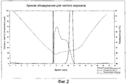
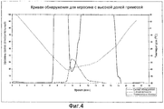
Фиг.2, 3, 4 - диаграммы, полученные программируемыми средствами расчета и отображения для соответственно образца чистого керосина, образца слабо загрязненного керосина и образца сильно загрязненного керосина, согласно изобретению.2, 3, 4 are diagrams obtained by programmable calculation and display tools for a sample of pure kerosene, a sample of slightly contaminated kerosene and a sample of highly contaminated kerosene, respectively, according to the invention.
Описание предпочтительных вариантов воплощения изобретенияDESCRIPTION OF PREFERRED EMBODIMENTS
Устройство для определения точки исчезновения кристаллов нефтепродуктов содержит криостатированную камеру 1 (Фиг.1), снабженную датчиком 2 температуры, а также установкой охлаждения и регулировки температуры, действующей по циклу Стирлинга (не показана).A device for determining the disappearance point of petroleum crystals contains a cryostat chamber 1 (FIG. 1) equipped with a
В криостатированной камере 1 размещена металлическая измерительная трубка 3 U-образной формы, горизонтальная центральная часть 4 которой представляет собой измерительную ячейку, в которую помещают анализируемый образец.In the
Боковые части 5 и 5' измерительной трубки 3 предназначены для ввода образца, а также его вывода.The
Устройство содержит также лазерный диод 6, напротив которого размещен продольный оптический приемник 7, чтобы испускаемый пучок 8 лазерного излучения проходил по одной линии с продольной осью измерительной ячейки 4 и через анализируемый образец, введенный в ячейку.The device also contains a
Перед продольным оптическим приемником 7 в направлении распространения лазерного луча от диода 6 установлен поляризатор 9.A
Поляризатор 9 настроен так, чтобы продольный оптический приемник 7 не принимал свет, когда образец, содержащийся в измерительной ячейке 4, прозрачный и не содержит кристаллов.The
Стеклянные окна 10, 10', имеющие абсолютно параллельные поверхности, позволяют лазерному лучу 8 проходить через измерительную ячейку 4 и достигать продольного оптического приемника 7, гарантируя герметичность этой ячейки.
Вспомогательный поляризатор 11, скрещенный с поляризатором 9 и установленный непосредственно за лазерным диодом 6, выполняет функцию ослабления амплитуды луча, испускаемого этим диодом.The
Вспомогательный поляризатор 11 действует вместе с диафрагмой 12, установленной непосредственно за ним, чтобы лазерный пучок, проходящий через измерительную ячейку 4, был достаточно тонким, чтобы совершенно исключить отражение на стенках этой ячейки.The
Устройство включает также боковой оптический приемник, установленный вблизи измерительной ячейки 4 у ее передней части.The device also includes a lateral optical receiver mounted near the measuring
Стеклянное окно 10", аналогичное окнам 10 и 10', позволяет лучу, рассеянному у передней части измерительной ячейкой 4, дойти до бокового оптического приемника 13.A
До достижения приемников 7, 13 поляризованный свет из поляризатора 9 и рассеянный свет, выходящий из окна 10", концентрируются на световодах 15, 15' линзами 14, 14', соответственно.Before reaching the
Установка охлаждения, датчик 2 температуры, а также продольный оптический приемник 7 и боковой оптический приемник 13 соединены с программируемыми средствами расчета и отображения (не показаны), которые управляют процессом в соответствии с заданным стандартом.The cooling installation, the
Программируемые средства расчета и отображения управляют установкой охлаждения криостатированной камеры 1 в зависимости от информации, которая передана им датчиком 2 температуры и приемниками 7, 13, и параллельно определяют кривую обнаружения, показывающую изменения в силе света, принятой продольным оптическим приемником 7, и кривую помутнения, показывающую изменения в силе света, полученного боковым оптическим приемником 13.Programmable calculation and display tools control the cooling installation of the
На Фиг.3, 4, 5 представлены три диаграммы, соответствующие трем разным образцам керосина, где по оси абсцисс отложено время, выраженное в минутах, а по оси ординат отложены сила света, полученная приемниками, выраженная в относительной шкале от 0 до 100, и температура образца, выраженная в °C, на левой шкале и правой шкале, соответственно.Figures 3, 4, 5 show three diagrams corresponding to three different samples of kerosene, where the time in minutes is plotted on the abscissa, and the luminous intensity obtained by receivers, expressed in a relative scale from 0 to 100, is plotted on the ordinate axis, and sample temperature, expressed in ° C, on the left scale and right scale, respectively.
Пунктирные кривые показывают изменения температуры образца как функцию времени (правая шкала).The dashed curves show changes in sample temperature as a function of time (right scale).
Штриховые линии соответствуют изменению помутнения и показывают изменения силы света во времени, полученной боковым приемником (левая шкала).The dashed lines correspond to the change in turbidity and show the change in light intensity in time obtained by the side receiver (left scale).
Сплошные линии соответствуют обнаружению и показывают изменения силы света от времени, полученной продольным приемником (правая шкала).The solid lines correspond to the detection and show the changes in light intensity versus time obtained by the longitudinal receiver (right scale).
Анализ трех диаграмм позволяет определить точку помутнения, то есть температуру, начиная с которой направление изменения температуры в криостатированной камере должно измениться на противоположное.An analysis of the three diagrams makes it possible to determine the cloud point, that is, the temperature, starting from which the direction of the temperature in the cryostat chamber should change to the opposite.
Сплошные кривые позволяют определить искомую точку исчезновения кристаллов.The solid curves make it possible to determine the desired disappearance point of the crystals.
В случае чистого керосина без примесей (Фиг.2) появление первых кристаллов было отмечено через 7 минут 30 секунд, или при температуре -59°C.In the case of pure kerosene without impurities (Figure 2), the appearance of the first crystals was noted after 7
Точка помутнения была обнаружена при температуре, очень близкой к -60°C.A cloud point was detected at a temperature very close to -60 ° C.
Точка исчезновения кристаллов была обнаружена через 11 минут, или при температуре -54°C.The crystal disappearance point was detected after 11 minutes, or at a temperature of -54 ° C.
В случае керосина с малым содержанием примесей (Фиг.3) появление первых кристаллов было отмечено через 6 минут 30 секунд, или при температуре -45°C, а точка помутнения через 7 минут 45 секунд, или при температуре -60°C.In the case of kerosene with a low content of impurities (Figure 3), the appearance of the first crystals was noted after 6
Исчезновение мутности в образце было отмечено через 11 минут 30 секунд, или при температуре -55°C, а точка исчезновения кристаллов через 13 минут 30 секунд, или при температуре -38,7°C.The disappearance of turbidity in the sample was noted after 11
«Скачок», отмеченный на кривой обнаружения около 12 минут, связан с физическими явлениями внутри образца.The “jump” noted on the detection curve for about 12 minutes is associated with physical phenomena inside the sample.
В случае сильно загрязненного керосина (Фиг.4) точка исчезновения кристаллов была отмечена через 14 минут 30 секунд, или при температуре -27,5°C.In the case of highly contaminated kerosene (Figure 4), the crystal disappearance point was noted after 14
Claims (7)
Applications Claiming Priority (2)
| Application Number | Priority Date | Filing Date | Title |
|---|---|---|---|
| FR0213577A FR2846748B1 (en) | 2002-10-30 | 2002-10-30 | METHOD FOR DETERMINING THE DISAPPEARANCE POINT OF CRYSTALS OF PETROLEUM PRODUCTS, AND DEVICE FOR CARRYING OUT SAID METHOD |
| FR02/13577 | 2002-10-30 |
Publications (2)
| Publication Number | Publication Date |
|---|---|
| RU2005116024A RU2005116024A (en) | 2006-01-27 |
| RU2291426C2 true RU2291426C2 (en) | 2007-01-10 |
Family
ID=32104305
Family Applications (1)
| Application Number | Title | Priority Date | Filing Date |
|---|---|---|---|
| RU2005116024/28A RU2291426C2 (en) | 2002-10-30 | 2003-10-29 | Method for determining disappearance point of oil product crystals and apparatus for performing the same |
Country Status (13)
| Country | Link |
|---|---|
| US (1) | US7338203B2 (en) |
| EP (1) | EP1563293B1 (en) |
| JP (1) | JP4323430B2 (en) |
| KR (1) | KR100692602B1 (en) |
| CN (1) | CN100465630C (en) |
| AT (1) | AT503508A2 (en) |
| AU (1) | AU2003292290A1 (en) |
| CA (1) | CA2503833C (en) |
| DE (2) | DE60317823T2 (en) |
| FR (1) | FR2846748B1 (en) |
| GB (1) | GB2412169A (en) |
| RU (1) | RU2291426C2 (en) |
| WO (1) | WO2004042385A1 (en) |
Cited By (1)
| Publication number | Priority date | Publication date | Assignee | Title |
|---|---|---|---|---|
| RU2685081C1 (en) * | 2018-07-30 | 2019-04-16 | Федеральное автономное учреждение "25 Государственный научно-исследовательский институт химмотологии Министерства обороны Российской Федерации" | Method for determination of turbidity of diesel fuel |
Families Citing this family (10)
| Publication number | Priority date | Publication date | Assignee | Title |
|---|---|---|---|---|
| CN101532962B (en) * | 2009-04-14 | 2012-04-25 | 中国地质大学(武汉) | Method and device for testing low-temperature property of drilling fluid |
| US8236168B2 (en) | 2009-10-13 | 2012-08-07 | Exxonmobil Research And Engineering Company | Onset haze measurement apparatus and procedure |
| JP5246173B2 (en) * | 2010-01-06 | 2013-07-24 | 株式会社日本自動車部品総合研究所 | Fuel property determination device |
| US8753007B2 (en) * | 2010-08-17 | 2014-06-17 | Honeywell Asca Inc. | Fuel cloud point or freeze point sensor with collinear optical geometry |
| CN103076332A (en) * | 2013-01-11 | 2013-05-01 | 中国电子科技集团公司第十一研究所 | System for measuring vaporization time |
| CN106444904A (en) * | 2016-09-18 | 2017-02-22 | 大顺国际花卉股份有限公司 | Greenhouse high temperature self-starting photoelectric switch and usage method |
| CN108801917A (en) * | 2018-06-21 | 2018-11-13 | 天津大学 | Dual-beam oil low temperature fluidity analysis system and method is miniaturized |
| FR3083416B1 (en) * | 2018-06-28 | 2020-05-29 | Safran Electronics & Defense | INFRARED IMAGING DEVICE |
| CN111830076B (en) * | 2019-04-19 | 2024-03-12 | 中国石油化工股份有限公司 | Method and device for detecting crystallization point and/or freezing point |
| CN112378862A (en) * | 2020-11-10 | 2021-02-19 | 河南工程学院 | High-low temperature cone light interference measuring device and method |
Family Cites Families (6)
| Publication number | Priority date | Publication date | Assignee | Title |
|---|---|---|---|---|
| FR1417250A (en) * | 1964-09-28 | 1965-11-12 | Cie De Raffinage Shell Berre | Method and apparatus for measuring the cloud point of liquids |
| US4519717A (en) * | 1982-06-07 | 1985-05-28 | Gca Corporation | On-stream cloud point analyzer |
| NL8203013A (en) * | 1982-07-28 | 1984-02-16 | Unie Van Kunstmestfab Bv | METHOD AND APPARATUS FOR DETERMINING THE SATURATION TEMPERATURE OF A SOLUTION |
| CA1316704C (en) * | 1988-02-10 | 1993-04-27 | Charles Yam-Chuen Tsang | Method and apparatus for monitoring cloud point |
| CN2093395U (en) * | 1991-06-25 | 1992-01-15 | 华祥荣 | Photoelectric type turbidimeter |
| FR2801381B1 (en) * | 1999-11-18 | 2002-01-04 | Instrumentation Scient De Labo | DEVICE FOR REFRIGERATING CELLS CONTAINING LIQUID SAMPLES IN PARTICULAR SAMPLES OF PETROLEUM PRODUCTS TO BE ANALYZED |
-
2002
- 2002-10-30 FR FR0213577A patent/FR2846748B1/en not_active Expired - Lifetime
-
2003
- 2003-10-29 AT AT0927803A patent/AT503508A2/en not_active Application Discontinuation
- 2003-10-29 RU RU2005116024/28A patent/RU2291426C2/en active
- 2003-10-29 EP EP03767856A patent/EP1563293B1/en not_active Expired - Lifetime
- 2003-10-29 CA CA002503833A patent/CA2503833C/en not_active Expired - Lifetime
- 2003-10-29 WO PCT/FR2003/003222 patent/WO2004042385A1/en active IP Right Grant
- 2003-10-29 KR KR1020057007706A patent/KR100692602B1/en active IP Right Grant
- 2003-10-29 JP JP2004549267A patent/JP4323430B2/en not_active Expired - Lifetime
- 2003-10-29 CN CNB2003801026954A patent/CN100465630C/en not_active Expired - Lifetime
- 2003-10-29 DE DE60317823T patent/DE60317823T2/en not_active Expired - Lifetime
- 2003-10-29 US US10/531,502 patent/US7338203B2/en not_active Expired - Lifetime
- 2003-10-29 AU AU2003292290A patent/AU2003292290A1/en not_active Abandoned
- 2003-10-29 DE DE10394308T patent/DE10394308T5/en not_active Withdrawn
-
2005
- 2005-04-20 GB GB0508008A patent/GB2412169A/en not_active Withdrawn
Cited By (1)
| Publication number | Priority date | Publication date | Assignee | Title |
|---|---|---|---|---|
| RU2685081C1 (en) * | 2018-07-30 | 2019-04-16 | Федеральное автономное учреждение "25 Государственный научно-исследовательский институт химмотологии Министерства обороны Российской Федерации" | Method for determination of turbidity of diesel fuel |
Also Published As
| Publication number | Publication date |
|---|---|
| DE10394308T5 (en) | 2006-08-17 |
| EP1563293B1 (en) | 2007-11-28 |
| CN100465630C (en) | 2009-03-04 |
| RU2005116024A (en) | 2006-01-27 |
| DE60317823D1 (en) | 2008-01-10 |
| JP4323430B2 (en) | 2009-09-02 |
| JP2006504967A (en) | 2006-02-09 |
| KR100692602B1 (en) | 2007-03-13 |
| DE60317823T2 (en) | 2008-10-30 |
| EP1563293A1 (en) | 2005-08-17 |
| FR2846748B1 (en) | 2005-04-22 |
| US7338203B2 (en) | 2008-03-04 |
| KR20050084620A (en) | 2005-08-26 |
| GB0508008D0 (en) | 2005-05-25 |
| AU2003292290A1 (en) | 2004-06-07 |
| CA2503833C (en) | 2010-01-12 |
| WO2004042385A1 (en) | 2004-05-21 |
| GB2412169A (en) | 2005-09-21 |
| FR2846748A1 (en) | 2004-05-07 |
| AT503508A2 (en) | 2007-10-15 |
| CN1711473A (en) | 2005-12-21 |
| CA2503833A1 (en) | 2004-05-21 |
| US20060098708A1 (en) | 2006-05-11 |
Similar Documents
| Publication | Publication Date | Title |
|---|---|---|
| US8207508B2 (en) | Device and method for quantifying a surface's cleanliness | |
| US4953976A (en) | Gas species monitor system | |
| US4663961A (en) | System for remote chemical analysis | |
| US5039855A (en) | Dual beam acousto-optic tunable spectrometer | |
| CA1280910C (en) | Dew point analyzer | |
| RU2291426C2 (en) | Method for determining disappearance point of oil product crystals and apparatus for performing the same | |
| US6118520A (en) | Dual analysis probe | |
| RU2438116C2 (en) | Installation for manufacture of sheet glass with equipment for measurement of stresses and procedure for control of device for glass drawing and hardening | |
| US8735851B2 (en) | Device and method for quantifying a surface's cleanliness | |
| US5381237A (en) | Multi-purpose optical head probe | |
| WO2015084967A1 (en) | Optical measurements of liquids having free surface | |
| JP2006504967A5 (en) | ||
| US20180080923A1 (en) | Toilet Bowl Optical Engine | |
| WO2010134834A1 (en) | Hydrocarbon dew point measuring method and device for implementing same | |
| JP4467933B2 (en) | Refractometer | |
| EP0257806B1 (en) | Dew point analyzer | |
| US7349092B1 (en) | System for reducing stress induced effects during determination of fluid optical constants | |
| RU2207564C2 (en) | Procedure determining concentration of alcohol and facility for its implementation | |
| CN108519354B (en) | Glass fragment source testing method | |
| US3663109A (en) | Viewing apparatus for use in a photometer | |
| RU2071056C1 (en) | Device for assaying milk and dairy products for content of fat and protein | |
| RU2352920C2 (en) | Method for determination of quantitative content of components in mixture | |
| Hercher | Virometer-an instrument for the measurement of the size of viruses using an optical microscope | |
| JPH05288683A (en) | Aniline-point measuring apparatus | |
| JPH04337447A (en) | Device and method for detecting light |