RU2230667C2 - Printing plate for compact printing of large area surfaces, method for its manufacture, information carrier with large-area printed image and method for metallographic printing - Google Patents
Printing plate for compact printing of large area surfaces, method for its manufacture, information carrier with large-area printed image and method for metallographic printing Download PDFInfo
- Publication number
- RU2230667C2 RU2230667C2 RU2001111870/12A RU2001111870A RU2230667C2 RU 2230667 C2 RU2230667 C2 RU 2230667C2 RU 2001111870/12 A RU2001111870/12 A RU 2001111870/12A RU 2001111870 A RU2001111870 A RU 2001111870A RU 2230667 C2 RU2230667 C2 RU 2230667C2
- Authority
- RU
- Russia
- Prior art keywords
- engraved
- partitions
- printing
- engraving
- printing form
- Prior art date
Links
Images
Classifications
-
- B—PERFORMING OPERATIONS; TRANSPORTING
- B41—PRINTING; LINING MACHINES; TYPEWRITERS; STAMPS
- B41M—PRINTING, DUPLICATING, MARKING, OR COPYING PROCESSES; COLOUR PRINTING
- B41M1/00—Inking and printing with a printer's forme
- B41M1/10—Intaglio printing ; Gravure printing
-
- B—PERFORMING OPERATIONS; TRANSPORTING
- B41—PRINTING; LINING MACHINES; TYPEWRITERS; STAMPS
- B41M—PRINTING, DUPLICATING, MARKING, OR COPYING PROCESSES; COLOUR PRINTING
- B41M3/00—Printing processes to produce particular kinds of printed work, e.g. patterns
- B41M3/14—Security printing
-
- B—PERFORMING OPERATIONS; TRANSPORTING
- B41—PRINTING; LINING MACHINES; TYPEWRITERS; STAMPS
- B41N—PRINTING PLATES OR FOILS; MATERIALS FOR SURFACES USED IN PRINTING MACHINES FOR PRINTING, INKING, DAMPING, OR THE LIKE; PREPARING SUCH SURFACES FOR USE AND CONSERVING THEM
- B41N1/00—Printing plates or foils; Materials therefor
- B41N1/04—Printing plates or foils; Materials therefor metallic
- B41N1/06—Printing plates or foils; Materials therefor metallic for relief printing or intaglio printing
-
- B—PERFORMING OPERATIONS; TRANSPORTING
- B42—BOOKBINDING; ALBUMS; FILES; SPECIAL PRINTED MATTER
- B42D—BOOKS; BOOK COVERS; LOOSE LEAVES; PRINTED MATTER CHARACTERISED BY IDENTIFICATION OR SECURITY FEATURES; PRINTED MATTER OF SPECIAL FORMAT OR STYLE NOT OTHERWISE PROVIDED FOR; DEVICES FOR USE THEREWITH AND NOT OTHERWISE PROVIDED FOR; MOVABLE-STRIP WRITING OR READING APPARATUS
- B42D25/00—Information-bearing cards or sheet-like structures characterised by identification or security features; Manufacture thereof
- B42D25/20—Information-bearing cards or sheet-like structures characterised by identification or security features; Manufacture thereof characterised by a particular use or purpose
- B42D25/29—Securities; Bank notes
-
- B42D2033/18—
-
- Y—GENERAL TAGGING OF NEW TECHNOLOGICAL DEVELOPMENTS; GENERAL TAGGING OF CROSS-SECTIONAL TECHNOLOGIES SPANNING OVER SEVERAL SECTIONS OF THE IPC; TECHNICAL SUBJECTS COVERED BY FORMER USPC CROSS-REFERENCE ART COLLECTIONS [XRACs] AND DIGESTS
- Y10—TECHNICAL SUBJECTS COVERED BY FORMER USPC
- Y10T—TECHNICAL SUBJECTS COVERED BY FORMER US CLASSIFICATION
- Y10T428/00—Stock material or miscellaneous articles
- Y10T428/24—Structurally defined web or sheet [e.g., overall dimension, etc.]
- Y10T428/24479—Structurally defined web or sheet [e.g., overall dimension, etc.] including variation in thickness
-
- Y—GENERAL TAGGING OF NEW TECHNOLOGICAL DEVELOPMENTS; GENERAL TAGGING OF CROSS-SECTIONAL TECHNOLOGIES SPANNING OVER SEVERAL SECTIONS OF THE IPC; TECHNICAL SUBJECTS COVERED BY FORMER USPC CROSS-REFERENCE ART COLLECTIONS [XRACs] AND DIGESTS
- Y10—TECHNICAL SUBJECTS COVERED BY FORMER USPC
- Y10T—TECHNICAL SUBJECTS COVERED BY FORMER US CLASSIFICATION
- Y10T428/00—Stock material or miscellaneous articles
- Y10T428/24—Structurally defined web or sheet [e.g., overall dimension, etc.]
- Y10T428/24802—Discontinuous or differential coating, impregnation or bond [e.g., artwork, printing, retouched photograph, etc.]
Abstract
Description
Изобретение относится к печатной форме, которая предназначена для сплошного запечатывания поверхности взаимосвязанных участков печатного изображения методом металлографской печати и воспроизводимое с помощью которой печатное изображение нанесено на ее поверхность в виде гравированных участков и к способу изготовления такой печатной формы. Изобретение относится также к носителю информации с полученным методом металлографской печати печатным изображением, имеющим по меньшей мере один участок с красочным слоем площадью более одного квадратного миллиметра, при этом указанный по меньшей мере один красочный слой покрывает поверхность этого участка печатного изображения по всей площади. Помимо этого изобретение относится к способу металлографской печати.The invention relates to a printing form, which is intended for continuous sealing of the surface of the interconnected sections of the printed image by metallographic printing and reproduced by means of which the printed image is applied to its surface in the form of engraved sections and to a method for manufacturing such a printing form. The invention also relates to a storage medium with a printed image obtained by the method of metallographic printing, having at least one area with a colorful layer with an area of more than one square millimeter, wherein said at least one colorful layer covers the surface of this portion of the printed image over the entire area. In addition, the invention relates to a method of metallographic printing.
При металлографской печати плоские изображения получают, как известно, с помощью расположенных близко друг к другу, т.е. с высокой плотностью, гравированных линий, при этом ширина отдельных гравированных линий, которые отделены друг от друга негравированными перегородками, составляет, как правило, несколько долей миллиметра.In metallographic printing, flat images are obtained, as is known, by means of those located close to each other, i.e. with high density, engraved lines, while the width of individual engraved lines, which are separated from each other by engraved partitions, is usually a few fractions of a millimeter.
Для процесса печатания гравированные линии печатной формы заполняют краской. Избыток краски удаляют с печатной формы стирающим валиком или ракелем таким образом, чтобы гравированные линии были до краев заполнены краской. Одновременно в ходе этой рабочей операции очищают и перегородки, расположенные между гравированными линиями.For the printing process, the engraved lines of the printing form are filled with ink. Excess ink is removed from the printing plate with an eraser roller or squeegee so that the engraved lines are filled to the brim with ink. At the same time, during this operation, the partitions located between the engraved lines are also cleaned.
В завершение в процессе печатания к печатной форме прижимным цилиндром, имеющим упругую поверхность, с высоким давлением, соответственно натиском прижимается запечатываемый носитель информации, обычно бумага. При этом материал носителя информации вдавливается в заполненные краской гравированные линии печатной формы и таким путем соприкасается с печатной краской. При отделении носителя информации от печатной формы печатная краска вытягивается из углублений гравированных линий. Полученный в результате оттиск состоит из напечатанных линий, толщина красочного слоя которых варьируется в зависимости от глубины гравировки.Finally, in the printing process, a pressable recording medium, usually paper, is pressed against the printing plate by a pressure cylinder having an elastic surface with a high pressure, respectively, on pressure. In this case, the material of the information carrier is pressed into the engraved lines of the printing form filled with ink and in this way comes into contact with the printing ink. When separating the storage medium from the printing form, the printing ink is drawn from the recesses of the engraved lines. The resulting print consists of printed lines, the thickness of the ink layer of which varies depending on the depth of the engraving.
Если при металлографской печати используют полупрозрачные печатные краски, то при запечатывании белого носителя информации краской с небольшой толщиной слоя получают светлые цветовые тона, а при запечатывании толстыми слоем краски получают более темные цветовые тона.If translucent printing inks are used for metallographic printing, then when printing a white information medium with ink with a small layer thickness, light color tones are obtained, and when printing with a thick layer of ink, darker color tones are obtained.
По сравнению с другими распространенными методами печати металлографская печать позволяет получать оттиски с очень большой толщиной красочного слоя. Полученные с помощью такого метода печати оттиски при использовании гравировки соответствующей глубины даже ощутимы на ощупь. С другой стороны, использование соответствующей тонкой гравировки позволяет печатать исключительно тонкие линии идеальной четкости.Compared with other common printing methods, metallographic printing allows you to get prints with a very large thickness of the ink layer. Impressions obtained using this printing method when using engraving of the appropriate depth are even palpable. On the other hand, the use of appropriate fine engraving allows you to print exceptionally thin lines of perfect definition.
Несмотря на возможность получать с помощью металлографской печати высококачественные, разложенные на линейные структуры оттиски недостаток этого метода печати состоит в невозможности получения сплошных запечатанных поверхностей большей площади, т.е. линий шириной примерно в один миллиметр и более. Обусловлено это тем, что при удалении избытка краски с закатанной краской печатной формы на участке гравировки с большой площадью поверхности снимается не только избыток краски, но и удаляется краска из самих выгравированных углублений. В результате уровень краски на этих выгравированных участках опускается ниже уровня поверхности печатной формы. Поскольку в этом случае вдавливаемая в выгравированные участки печатной формы бумага не во всех местах достигает поверхности краски, в оттиске образуются пропуски или пробелы, делающие этот оттиск непригодным.Despite the possibility of obtaining high-quality impressions decomposed into linear structures using metallographic printing, the drawback of this printing method is the impossibility of obtaining continuous sealed surfaces of a larger area, i.e. lines about one millimeter or more wide. This is due to the fact that when removing excess ink with rolled-up ink of a printing form on an engraving site with a large surface area, not only the excess of ink is removed, but also the ink is removed from the engraved recesses themselves. As a result, the ink level in these engraved areas drops below the surface level of the printing plate. Since in this case the paper pressed into the engraved sections of the printing form does not reach the surface of the ink in all places, gaps or spaces form in the print, making this print unsuitable.
Исходя из вышеизложенного, в основу настоящего изобретения была положена задача разработать соответствующие меры, которые при металлографской печати обеспечивали бы сплошное запечатывание больших по площади участков оттиска таким образом, чтобы запечатанная поверхность зрительно воспринималась как равномерно окрашенная.Based on the foregoing, the present invention was based on the task of developing appropriate measures that, when metallographic printing, would ensure the continuous sealing of large areas of the print so that the sealed surface was visually perceived as uniformly colored.
В отношении печатной формы, которая предназначена для сплошного запечатывания поверхности взаимосвязанных участков печатного изображения методом металлографской печати и воспроизводимое с помощью которой печатное изображение нанесено на ее поверхность в виде гравированных участков, указанная задача решается благодаря тому, что на гравированных заполняемых краской участках печатной формы предусмотрены перегородки, разделяющие эти гравированные участки на более мелкие участки, при этом указанные перегородки выполнены таким образом, что они не имеют поверхностей, лежащих на уровне поверхности печатной формы.With respect to the printing form, which is designed for continuous sealing of the surface of interconnected sections of the printed image by metallographic printing and reproduced by means of which the printed image is applied to its surface in the form of engraved sections, this problem is solved due to the fact that partitions are provided on the engraved ink-filled sections of the printing form separating these engraved sections into smaller sections, while these partitions are made in such a way m, that they do not have surfaces lying at the level of the surface of the printing form.
Основная идея изобретения состоит в том, чтобы при стирании избытка краски с печатного цилиндра, соответственно с печатной формы, предотвратить нежелательное удаление печатной краски и из углублений на гравированном участке, для чего в гравировке предусматривают так называемые перегородки, препятствующие или по крайней мере сводящие к минимуму воздействие стирающего валика на печатную краску, которой заполнены выгравированные углубления печатной формы. Не основываясь на какой-либо теории, полагают, что образуемая избытком краски волна, поднимаемая стирающим валиком и движущаяся перед ним в процессе его перемещения по поверхности печатной формы, под действием гидродинамических сил захватывает и часть краски из гравированных углублений. Очевидно, что перегородки предотвращают перемещение всего объема находящейся в гравировке печатной краски, не давая создаваемой стирающим валиком волне краски увлекать ее вместе с собой. В результате перегородки разделяют гравировку большей площади на смежные "камеры" или каналы, которые, с одной стороны, допускают извлечение из них печатной краски перпендикулярно поверхности печатной формы в процессе печатания, но которые, с другой стороны, препятствуют подобному удалению из них краски параллельно поверхности печатной формы в процессе стирания избытка краски.The main idea of the invention is that when erasing excess ink from the printing cylinder, respectively, from the printing form, to prevent unwanted removal of printing ink and from the recesses in the engraved area, for which the so-called partitions are provided in the engraving to prevent or at least minimize the effect of the eraser on the printing ink, which engraved engraved recesses of the printing form. Not based on any theory, it is believed that the wave formed by the excess of ink, lifted by the erasing roller and moving in front of it during its movement on the surface of the printing form, also captures part of the paint from the engraved recesses under the action of hydrodynamic forces. It is obvious that the partitions prevent the movement of the entire volume of printing ink in the engraving, preventing the wave of ink created by the erasing roller from dragging it along with itself. As a result, the partitions divide the engraving of a larger area into adjacent “chambers” or channels, which, on the one hand, allow the extraction of printing ink perpendicular to the surface of the printing form during printing, but which, on the other hand, prevent similar removal of ink from them parallel to the surface plate in the process of erasing excess ink.
В соответствии с одним из предпочтительных вариантов гравированными участками являются гравированные линии и/или гравированные элементы большой площади. В этом случае целесообразно, чтобы ширина гравированных линий составляла более 0,5 мм, предпочтительно более 1,0 мм.In one preferred embodiment, the engraved sections are engraved lines and / or engraved elements of a large area. In this case, it is advisable that the width of the engraved lines is more than 0.5 mm, preferably more than 1.0 mm.
Перегородки предпочтительно располагать поперечно направлению вращения стирающего валика. Очевидно, что при таком расположении они позволяют отсечь возникающую в процессе снятия избытка краски волну и тем самым гидродинамически отделить заполняющую гравировку печатную краску от ее избытка, снимаемого с поверхности печатной формы. В соответствии с этим согласно еще одному варианту выполнения предлагаемой в изобретении печатной формы гравированными участками являются гравированные линии, а перегородки проходят поперечно гравированной линии, в результате чего образуются расположенные в ряд более мелкие участки, причем перегородки проходят поперечно или диагонально к направлению снятия избытка краски.Partitions are preferably arranged transverse to the direction of rotation of the erasing roller. Obviously, with this arrangement, they allow you to cut off the wave that occurs during the removal of excess ink and thereby hydrodynamically separate the printing ink filling the engraving from its excess, which is removed from the surface of the printing form. In accordance with this, according to another embodiment of the printing form of the invention, the engraved sections are engraved lines, and the partitions extend transversely to the engraved line, resulting in the formation of smaller sections arranged in a row, the partitions extending transversely or diagonally to the direction of removing excess ink.
В тех случаях, когда перегородки невозможно расположить поперечно направлению стирания, подобные перегородки обеспечивают по меньшей мере разделение на более мелкие участки гравировок большой площади, придавая им с точки зрения удержания в них краски при стирании ее избытка свойства, аналогичные тем, которыми обладают гравировки с мелкой (высоколиниатурной) структурой. В соответствии с этим согласно другому варианту выполнения предлагаемой в изобретении печатной формы гравированными участками являются гравированные линии, а перегородки проходят параллельно гравированной линии и поперечно или диагонально к направлению снятия избытка краски.In those cases when it is impossible to arrange the partitions transversely to the direction of erasure, such partitions provide at least separation into smaller sections of engravings of a large area, giving them, from the point of view of the retention of paint in them when erasing its excess, properties similar to those possessed by fine engraving (high-tin) structure. In accordance with this, according to another embodiment of the printed form of the invention, the engraved sections are engraved lines, and the partitions run parallel to the engraved line and transversely or diagonally to the direction of removing excess ink.
Таким образом, с учетом основной идеи изобретения гравированные участки целесообразно снабжать перегородками, располагая их предпочтительно поперечно направлению стирания избытка краски. В случае гравированных линий, которые проходят вдоль направления стирания, такие перегородки обеспечивают разбиение указанных гравированных линий на расположенные в ряд более мелкие участки. В соответствии с этим согласно следующему варианту выполнения предлагаемой в изобретении печатной формы гравированными участками являются гравированные линии, а перегородки проходят поперечно гравированной линии, в результате чего образуются расположенные в ряд более мелкие участки, причем перегородки проходят поперечно или диагонально к направлению снятия избытка краски. Гравировку, проходящую поперечно или диагонально к направлению стирания избытка краски, разбивают на более мелкие участки по меньшей мере в продольном направлении гравированной линии, при этом перегородки предпочтительно располагать параллельно краям гравировки. В соответствии с этим согласно другому варианту выполнения предлагаемой в изобретении печатной формы гравированными участками являются гравированные линии, а перегородки проходят параллельно гравированной линии и поперечно или диагонально к направлению снятия избытка краски.Thus, taking into account the main idea of the invention, it is advisable to provide the engraved sections with partitions, preferably disposing transverse to the direction of erasing the excess paint. In the case of engraved lines that run along the direction of erasure, such partitions provide a breakdown of these engraved lines in a series of smaller areas. In accordance with this, according to the next embodiment of the printing form of the invention, the engraved sections are engraved lines, and the partitions extend transversely to the engraved line, resulting in the formation of smaller sections arranged in a row, the partitions extending transversely or diagonally to the direction of removing excess ink. An engraving extending transversely or diagonally to the direction of erasing the excess paint is divided into smaller sections at least in the longitudinal direction of the engraved line, with the walls preferably being parallel to the edges of the engraving. In accordance with this, according to another embodiment of the printed form of the invention, the engraved sections are engraved lines, and the partitions run parallel to the engraved line and transversely or diagonally to the direction of removing excess ink.
В тех случаях, когда гравировка состоит не только из очень широких гравированных линий, но и из больших по площади гравированных элементов примерно одинаковых размеров в направлениях x и y, перегородки можно выполнять и в виде растра, т.е. предусматривать пересекающиеся перегородки, проходящие, например, продольно и поперечно относительно направления стирания. Равным образом существует возможность выполнять перегородки в виде концентричных кругов, сотовой структуры и т.п. Преимущество подобного выполнения перегородок заключается не только в том, что эти перегородки будут в любом случае выполнять предусмотренную для них функцию независимо от направления, в котором стиранием снимается избыток краски, но и в придании перегородкам более высокой механической прочности. В соответствии с этим согласно следующему варианту выполнения предлагаемой в изобретении печатной формы перегородки расположены на гравированном участке таким образом, что они образуют равномерную мелкую структуру в виде растра или регулярного рисунка. Указанный растр предпочтительно представляет собой линейный растр или растр с перекрещивающимися линиями. В последнем случае предпочтительно, чтобы растр с перекрещивающимися линиями состоял из первой гравировки с параллельными, предпочтительно прямыми, гравированными линиями и наложенной на эту первую гравировку второй гравировки с параллельными, предпочтительно прямыми, гравированными линиями. При этом целесообразно, чтобы линии первой гравировки пересекали линии второй гравировки под углом от 20 до 90°, предпочтительно от 40 до 70°.In cases where the engraving consists not only of very wide engraved lines, but also of large-sized engraved elements of approximately the same size in the x and y directions, the partitions can also be made in the form of a raster, i.e. provide intersecting partitions, passing, for example, longitudinally and transversely with respect to the direction of erasure. Similarly, it is possible to make partitions in the form of concentric circles, honeycomb structure, etc. The advantage of such a design of the partitions is not only that these partitions will in any case fulfill the function provided for them regardless of the direction in which excess paint is removed by erasing, but also in giving the partitions a higher mechanical strength. In accordance with this, according to a further embodiment of the printed form of the invention, the partitions are arranged in an engraved portion so that they form a uniform fine structure in the form of a raster or a regular pattern. The specified raster is preferably a linear raster or a raster with intersecting lines. In the latter case, it is preferable that the raster with intersecting lines consist of a first engraving with parallel, preferably straight, engraved lines and a second engraving superimposed on this first engraving with parallel, preferably straight, engraved lines. It is advisable that the lines of the first engraving intersect the lines of the second engraving at an angle of 20 to 90 °, preferably from 40 to 70 °.
Как указано выше, перегородки наиболее предпочтительно предусматривать в гравировке печатной формы для металлографской печати, начиная с ширины гравированных линий более 0,5 мм. При ширине гравированных линий в 1 мм и более наличие этих перегородок становится практически обязательным.As indicated above, it is most preferable to provide partitions in the engraving of the printing plate for metallographic printing, starting from a width of the engraved lines of more than 0.5 mm. With a width of engraved lines of 1 mm or more, the presence of these partitions becomes almost mandatory.
Высоту этих перегородок можно, как показали эксперименты, варьировать в относительно широких пределах. Если перегородки оканчиваются на уровне поверхности печатной формы, то перегородкам необходимо придавать в сечении клиновидно заостренную форму. При такой форме, с одной стороны, перегородки обеспечивают оптимальное разбиение гравировки на отделенные друг от друга каналы или камеры, а с другой стороны, благодаря заостренным краям перегородок исключается появление разрывов в запечатываемой поверхности.The height of these partitions can, as shown by experiments, vary within a relatively wide range. If the partitions end at the level of the surface of the printing form, then the partitions must be given a wedge-shaped pointed cross-section. With this form, on the one hand, the partitions provide an optimal breakdown of the engraving into channels or chambers separated from each other, and on the other hand, thanks to the pointed edges of the partitions, gaps in the sealing surface are eliminated.
Если верхние края перегородок располагать ниже уровня поверхности печатной формы, то перегородкам в принципе можно придавать практически любой отличный от клиновидного профиль в сечении, т.е. выполнять их трапециевидной, скругленной или иной в сечении формы. Поскольку верхние края перегородок в этом случае всегда расположены ниже уровня поверхности печатной формы и поэтому всегда находятся ниже уровня печатной краски, при таком выполнении перегородок также в любом случае обеспечивается запечатывание соответствующей поверхности по всей ее площади без разрывов и пробелов.If the upper edges of the partitions are located below the surface of the printing plate, then in principle, almost any profile that is different from the wedge-shaped section can be given to the partitions, i.e. to perform them trapezoidal, rounded or different in shape. Since the upper edges of the partitions in this case are always below the surface level of the printing form and therefore are always below the level of printing ink, with this design of the partitions, the sealing of the corresponding surface over its entire area is also provided in any case without gaps and gaps.
Было установлено, что применение перегородок, верхний край которых оканчивается точно на уровне поверхности печатной формы, приводит к сравнительно быстрому износу поверхности стирающего валика. Поэтому для решения указанной проблемы верхние края перегородок следует располагать ниже поверхности печатной формы на величину, составляющую не менее 2-5 мкм. Подобное минимальное уменьшение высоты перегородок в любом случае является целесообразным.It was found that the use of partitions, the upper edge of which ends exactly at the level of the surface of the printing form, leads to a relatively quick wear of the surface of the erasing roller. Therefore, to solve this problem, the upper edges of the partitions should be located below the surface of the printing form by an amount of at least 2-5 microns. Such a minimal reduction in the height of the partitions is in any case advisable.
Предпочтительно, чтобы высота перегородок составляла от 3 до 150 мкм, более предпочтительно от 8 до 60 мкм. При этом соотношение между высотой перегородок и глубиной гравировки предпочтительно должно составлять от 0,5 до 1.Preferably, the height of the partitions is from 3 to 150 microns, more preferably from 8 to 60 microns. Moreover, the ratio between the height of the partitions and the depth of the engraving should preferably be from 0.5 to 1.
Проведенные эксперименты, кроме того, показали, что верхние края перегородок можно располагать и на значительно более низком уровне. В соответствии с этим величина, на которую можно уменьшать высоту перегородок ниже уровня поверхности печатной формы, может составлять до 50% от глубины гравировки.The experiments, in addition, showed that the upper edges of the partitions can be located at a much lower level. In accordance with this, the value by which the height of the partitions can be reduced below the surface level of the printing form can be up to 50% of the engraving depth.
Было установлено также, что перегородки, высота которых, называемая ниже также амплитудой, составляет более 50% от глубины гравировки, приводят к появлению своего рода "насечек" на поверхности красочного слоя на запечатываемой с их помощью поверхности. Хотя поверхность, запечатанная с помощью подобной большой по площади гравировки, и покрыта полностью краской, перегородки придают этой поверхности определенную рельефность. При этом подобная поверхность имеет наиболее выраженную рельефность в том случае, когда амплитуда перегородок составляет от 75 до 100% от глубины гравировки. При меньших амплитудах, например порядка 60%, такая рельефность поверхности постепенно становится менее выраженной и окончательно сходит на нет при амплитуде, составляющей примерно 50%. При значениях менее 50%, прежде всего при более глубокой гравировке, возрастает вероятность появления дефектов печати в виде пробелов или пропусков, делающих оттиск непригодным.It was also found that the partitions, the height of which, also called amplitude below, is more than 50% of the engraving depth, lead to a kind of “notches” on the surface of the ink layer on the surface sealed with their help. Although a surface sealed with a similar large engraving area is completely covered with paint, partitions give this surface a certain relief. Moreover, such a surface has the most pronounced relief in the case when the amplitude of the partitions is from 75 to 100% of the engraving depth. At lower amplitudes, for example, of the order of 60%, such surface relief gradually becomes less pronounced and finally disappears at an amplitude of approximately 50%. At values of less than 50%, primarily with deeper engraving, the likelihood of printing defects in the form of spaces or omissions, making the print unsuitable, increases.
Помимо этого проведенные эксперименты показали, что в соответствии с изобретением исключительно высокое качество печати достигается в том случае, когда глубина гравировки составляет от 5 до примерно 150 мкм. Было установлено, что для получения наиболее распространенных печатных изображений, соответственно оттисков глубина гравировки предпочтительно должна составлять от 10 до 60 мкм. При использовании обычных красок для металлографской печати гравировка подобной глубины позволяет получать красочные слои, которые большей частью воспринимаются как просвечивающие, полупрозрачные, а уже незначительное изменение глубины гравировки позволяет получить четко различимое на глаз изменение цветового тона. Гравировка глубиной примерно от 60 до 100 мкм наиболее пригодна для печатания красочных слоев, производящих впечатление насыщенной, кроющей краски. Точные значения глубины, как очевидно, будут варьироваться в зависимости от того, идет ли речь о светлой или о темной краске.In addition, the experiments showed that in accordance with the invention an exceptionally high print quality is achieved when the engraving depth is from 5 to about 150 microns. It was found that to obtain the most common printed images, respectively prints, the engraving depth should preferably be from 10 to 60 microns. When using conventional inks for metallographic printing, engraving of a similar depth allows you to get colorful layers that are mostly perceived as translucent, translucent, and even a slight change in the depth of engraving allows you to get a clearly visible change in color tone. An engraving depth of about 60 to 100 microns is most suitable for printing colorful layers that give the impression of a rich, hiding ink. The exact depths will obviously vary depending on whether it is light or dark paint.
Гравировка глубиной 100 мкм и более наиболее пригодна для получения красочных слоев с хорошо различимой на ощупь рельефной структурой.Engraving with a depth of 100 microns and more is most suitable for obtaining colorful layers with a clearly distinguishable touch structure.
Предпочтительно далее, чтобы верхние края перегородок располагались на некотором расстоянии друг от друга, которое больше или равно ширине контакта гравировального инструмента, используемого для гравирования соответствующего участка.It is further preferred that the upper edges of the partitions are spaced apart from each other, which is greater than or equal to the contact width of the engraving tool used to engrave the corresponding portion.
Расстояние, на которое отстоят друг от друга верхние края перегородок, предпочтительно составляет менее 500 мкм, более предпочтительно от 20 до 150 мкм, наиболее предпочтительно 50 мкм. В принципе, чем мельче тонкая (высоколиниатурная) структура рельефной запечатанной поверхности, тем сложнее ее разглядеть без помощи вспомогательных средств (например лупы). Сказанное относится по меньшей мере к тонким, соответственно мелким структурам, получаемым с помощью перегородок, шаг между которыми составляет примерно от 20 до 150 мкм и которые имеют клиновидную форму. Перегородки, расположенные с шагом в пределах от 150 до примерно 400 мкм, хотя уже и различимы невооруженным глазом, тем не менее они ни в коей мере не ухудшают общего впечатления, создаваемого сплошной запечатанной краской поверхностью. При использовании перегородок не клиновидного, а трапециевидного в сечении профиля, имеющиеся на рельефной поверхности насечки становятся шире, т.е. занимают большую площадь. Подобные структуры позволяют влиять на оформление запечатываемой поверхности за счет использования, например, образуемого перегородками растра в качестве видимого элемента оформления. При включении в гравировку перегородок не в виде растра, а в виде шрифтовых знаков, графических символов и т.п. подобные шрифтовые знаки или графические символы также будут различимы на запечатанной поверхности.The distance by which the upper edges of the partitions are spaced apart is preferably less than 500 microns, more preferably 20 to 150 microns, most preferably 50 microns. In principle, the finer the thin (high-linear) structure of a relief sealed surface, the more difficult it is to see without the help of auxiliary means (such as a magnifying glass). The foregoing refers to at least thin, respectively small structures obtained by means of partitions, the pitch between which is from about 20 to 150 microns and which are wedge-shaped. Partitions located in increments ranging from 150 to about 400 microns, although they are already visible to the naked eye, nevertheless they in no way worsen the overall impression created by a solid, sealed paint surface. When using partitions not of a wedge-shaped, but of a trapezoidal profile in the section, the notches present on the relief surface become wider, i.e. occupy a large area. Such structures allow you to influence the design of the printed surface by using, for example, a raster formed by the partitions as a visible design element. When partitions are included in the engraving, not in the form of a raster, but in the form of font characters, graphic symbols, etc. similar font characters or graphic characters will also be visible on the sealed surface.
С увеличением расстояния между перегородками до значений, существенно превышающих 500 мкм, возрастает и количество указанных в начале описания дефектов печати в виде пробелов, пропусков, пятен и т.п.With an increase in the distance between the partitions to values significantly exceeding 500 μm, the number of printing defects indicated at the beginning of the description in the form of spaces, gaps, spots, etc. also increases.
Предпочтительно далее, чтобы в предлагаемой в изобретении печатной форме перегородки за счет их параллельного расположения образовывали линейную мелкую структуру. В этом случае печатная форма должна быть согласована для ее применения вместе с прижимным цилиндром таким образом, чтобы линейная мелкая структура располагалась в основном параллельно оси вращения этого прижимного цилиндра.It is further preferred that in the printed form of the invention, the partitions, due to their parallel arrangement, form a linear fine structure. In this case, the printing plate must be coordinated for its use with the pressure cylinder so that the linear fine structure is located mainly parallel to the axis of rotation of this pressure cylinder.
В соответствии еще с одним предпочтительным вариантом выполнения предлагаемой в изобретении печатной формы и длина, и ширина гравированного участка составляют более 1 мм.According to another preferred embodiment of the printing plate according to the invention, both the length and the width of the engraved portion are more than 1 mm.
Согласно еще одному варианту предлагаемая в изобретении печатная форма имеет по меньшей мере первый и второй гравированные участки, различающиеся формой и/или расположением перегородок. В этом случае предпочтительно, чтобы ориентация перегородок на первом гравированном участке была отлична от ориентации перегородок на втором гравированном участке. Более предпочтительно располагать перегородки на первом гравированном участке под прямым углом к перегородкам на втором гравированном участке. Предпочтительно также, чтобы глубина гравировки на первом гравированном участке была отлична от глубины гравировки на втором гравированном участке. При этом предпочтительно, чтобы верхние края перегородок на первом гравированном участке отстояли друг от друга на большее расстояние, чем верхние края перегородок на втором гравированном участке. Помимо этого предпочтительно, чтобы верхние края перегородок на втором гравированном участке отстояли от поверхности печатной формы на большее расстояние, чем верхние края перегородок на первом гравированном участке. Первый и второй гравированные участки предпочтительно также выполнять примыкающими друг к другу.According to another embodiment, the printing form according to the invention has at least first and second engraved portions differing in the shape and / or arrangement of the partitions. In this case, it is preferable that the orientation of the partitions in the first engraved area is different from the orientation of the partitions in the second engraved area. It is more preferable to place the partitions in the first engraved area at right angles to the partitions in the second engraved area. It is also preferred that the engraving depth in the first engraved area is different from the engraving depth in the second engraved area. In this case, it is preferable that the upper edges of the partitions in the first engraved area are separated from each other by a greater distance than the upper edges of the partitions in the second engraved area. In addition, it is preferable that the upper edges of the partitions in the second engraved area are separated from the surface of the printing form by a greater distance than the upper edges of the partitions in the first engraved area. The first and second engraved sections are preferably also adjacent to each other.
В изобретении предлагается также носитель информации с полученным методом металлографской печати печатным изображением, имеющим по меньшей мере один участок с красочным слоем площадью более одного квадратного миллиметра, при этом указанный по меньшей мере один красочный слой покрывает поверхность этого участка печатного изображения по всей площади. Подобный носитель информации отличается тем, что размеры сторон указанной поверхности, такие как ее длина и ширина, составляют более 0,5 мм, а красочный слой имеет проходящую в одном направлении по меньшей мере одну насечку, в месте расположения которой красочный слой имеет минимальную толщину.The invention also provides a storage medium with a printed image obtained by the method of metallographic printing, having at least one region with an ink layer with an area of more than one square millimeter, wherein said at least one ink layer covers the surface of this region of the printed image over the entire area. Such a storage medium is characterized in that the dimensions of the sides of said surface, such as its length and width, are more than 0.5 mm, and the ink layer has at least one notch extending in one direction, at the location of which the ink layer has a minimum thickness.
Предпочтительно, чтобы размеры сторон указанной поверхности, такие как ее длина и ширина, составляли более 1 мм.Preferably, the dimensions of the sides of said surface, such as its length and width, are greater than 1 mm.
Согласно одному из предпочтительных вариантов выполнения носителя информации указанный по меньшей мере один красочный слой имеет рельефную поверхность, которая образована мелкой структурой с регулярно повторяющимися структурными элементами. В этом случае предпочтительно, чтобы структурные элементы повторялись с шагом менее 0,5 мм.According to one preferred embodiment of the information carrier, said at least one ink layer has a relief surface that is formed by a fine structure with regularly repeating structural elements. In this case, it is preferable that the structural elements are repeated in increments of less than 0.5 mm.
В соответствии со следующим предпочтительным вариантом выполнения предлагаемого в изобретении носителя информации указанная выше мелкая структура образует растр или регулярный рисунок. Предпочтительно, чтобы такой растр представлял собой линейный растр или растр с перекрещивающимися линиями. Предпочтительно далее, чтобы мелкая структура образовывала растр с шириной линий менее 150 мкм.According to a further preferred embodiment of the information carrier according to the invention, the aforementioned fine structure forms a raster or a regular pattern. Preferably, such a raster is a linear raster or a raster with intersecting lines. It is further preferred that the fine structure forms a raster with a line width of less than 150 microns.
Согласно еще одному предпочтительному варианту выполнения носителя информации предусмотренное у него печатное изображение имеет по меньшей мере первый участок с первой мелкой структурой и второй участок со второй мелкой структурой, отличной от первой. В этом случае предпочтительно, чтобы первые и вторые участки печатного изображения представляли собой один или несколько шрифтовых знаков или графическое изображение. Предпочтительно также, чтобы ориентация мелкой структуры на первом участке печатного изображения была отлична от ориентации мелкой структуры на втором участке печатного изображения. В соответствии со следующим предпочтительным вариантом мелкие структуры на первом и втором участках печатного изображения различаются шириной линий. Помимо этого предпочтительно, чтобы первый и второй участки печатного изображения различались толщиной красочного слоя.According to another preferred embodiment of the storage medium, the printed image provided for it has at least a first section with a first fine structure and a second section with a second fine structure different from the first. In this case, it is preferable that the first and second portions of the printed image are one or more font characters or a graphic image. It is also preferred that the orientation of the fine structure in the first portion of the printed image is different from the orientation of the fine structure in the second portion of the printed image. According to a further preferred embodiment, the fine structures in the first and second portions of the printed image differ in line widths. In addition, it is preferable that the first and second portions of the printed image differ in the thickness of the ink layer.
С учетом того факта, что технология изготовления печатных форм для металлографской печати как таковая уже относится к наиболее сложным методам изготовления печатных форм, очевидно, что наличие дополнительных перегородок в гравировке создает значительные дополнительные проблемы. Острота подобных проблем возрастает еще и в связи с тем, что для выполнения предлагаемой в изобретении функции требуется не только наличие у перегородок соответствующей формы, амплитуды и расположения, но и микронная точность их изготовления. Вручную или травлением подобные печатные формы изготовить невозможно. Поэтому предлагаемые в изобретении печатная продукция и печатные формы обеспечивают высокую степень их защиты от подделки и копирования.Given the fact that the technology for the manufacture of printing plates for metallographic printing as such already belongs to the most complex methods for the manufacture of printing plates, it is obvious that the presence of additional partitions in engraving creates significant additional problems. The severity of such problems also increases due to the fact that in order to perform the function proposed in the invention, it is required not only that the partitions have the appropriate shape, amplitude and location, but also the micron accuracy of their manufacture. It is impossible to make such plates manually or by etching. Therefore, the printed products and printing forms of the invention provide a high degree of protection against counterfeiting and copying.
Вместе с тем, изготавливать подобные печатные формы можно с помощью гравировального устройства, описанного в заявке WO 97/48555. Такое устройство позволяет изготавливать печатные формы для металлографской печати фрезерованием с компьютерным управлением. С этой целью в компьютер вводятся данные о расположении линий на двухмерном штриховом рисунке, служащим оригиналом, и точно задается площадь каждой отдельной линии. После этого гравировальным инструментом, например вращающимся штихелем или лазерным лучом, вначале гравируется наружный контур этих поверхностей для получения их точного очертания или окантовки. Затем на этом окантованном участке поверхности тем же или иным гравировальным инструментом снимается материал с получением в результате всей линии, точно выгравированной в соответствии со штриховым оригиналом. При этом в зависимости от типа гравировального инструмента и от управления его перемещением донной поверхности гравировки можно придавать определенную шероховатость (вместо получения гладкой поверхности), а также получать предлагаемые в изобретении перегородки любой амплитуды, с различными углами наклона их боковых поверхностей или с точно заданным профилем в сечении. Важным моментом при этом, как уже было указано в начале описания, является то, что для выполнения предлагаемой в изобретении функции минимальная амплитуда перегородок должна составлять примерно 50% от глубины гравировки. При значениях, которые значительно меньше указанного, гравированные элементы большой площади неизбежно приводят к появлению указанных в начале описания дефектов печати даже несмотря на то, что печатная краска и удерживается в этом случае на донной поверхности гравировки значительно эффективнее, чем в гравировке с гладкой донной поверхностью.However, it is possible to produce such printing plates using the engraving device described in WO 97/48555. Such a device allows the manufacture of printing plates for metallographic printing by computer-controlled milling. For this purpose, data on the location of lines in a two-dimensional line drawing, which serves as the original, is entered into the computer, and the area of each individual line is precisely set. After that, with an engraving tool, such as a rotating shtikhel or a laser beam, the outer contour of these surfaces is first engraved to obtain their exact outline or border. Then, material is removed on this edged surface with the same or another engraving tool, resulting in an entire line that is precisely engraved in accordance with the dashed original. In this case, depending on the type of engraving tool and on the control of its movement of the bottom surface of the engraving, you can give a certain roughness (instead of obtaining a smooth surface), as well as obtain the proposed in the invention partitions of any amplitude, with different angles of inclination of their side surfaces or with a precisely defined profile in section. An important point in this case, as already indicated at the beginning of the description, is that in order to perform the function proposed in the invention, the minimum amplitude of the partitions should be approximately 50% of the engraving depth. For values that are significantly less than the indicated, engraved elements of a large area inevitably lead to the appearance of printing defects indicated at the beginning of the description, even though the printing ink is retained in this case on the bottom surface of the engraving much more effectively than in engraving with a smooth bottom surface.
В соответствии с этим в изобретении предлагается также способ изготовления печатной формы, предназначенной для сплошного запечатывания методом металлографской печати поверхности большой площади, заключающийся в том, что подготавливают заготовку для печатной формы с соответствующей поверхностью и затем на поверхности этой заготовки печатной формы гравировальным инструментом гравируют по меньшей мере один соответствующий запечатываемой поверхности большой площади участок таким образом, чтобы оставались перегородки, выступающие в этом гравированном участке и разделяющие его на более мелкие участки, при этом указанным перегородкам в результате гравирования придают такую форму, чтобы они не имели поверхностей, лежащих на уровне поверхности печатной формы.In accordance with this, the invention also provides a method for manufacturing a printing plate intended for continuous sealing by metallographic printing of a large area surface, comprising preparing a printing blank with a corresponding surface and then engraving with at least one engraving tool on the surface of this printing blank at least one area corresponding to the large surface to be sealed so that there are partitions protruding in is engraved portion and dividing it into smaller portions, wherein said partitions in the engraving result shaped so that they do not have surfaces that lie at the level of printing plate surface.
Гравированные участки предпочтительно гравировать в виде линий и/или элементов большой площади. В этом случае гравированные линии целесообразно выполнять шириной более 0,5 мм, предпочтительно более 1,0 мм.Engraved sections are preferably engraved in the form of lines and / or elements of a large area. In this case, it is advisable to make engraved lines with a width of more than 0.5 mm, preferably more than 1.0 mm.
В соответствии еще с одним предпочтительным вариантом осуществления предлагаемого в изобретении способа изготовления печатной формы гравированные участки гравируют в виде гравированных линий, а перегородки выполняют поперечно гравированной линии, в результате чего образуются расположенные в ряд более мелкие участки, при этом перегородки проходят поперечно или диагонально к направлению снятия избытка краски.In accordance with another preferred embodiment of the inventive method for manufacturing a printing plate, the engraved sections are engraved in the form of engraved lines, and the partitions are transversely engraved lines, resulting in the formation of smaller sections arranged in a row, with the partitions extending transversely or diagonally to the direction removing excess paint.
В другом варианте гравированные участки предлагается гравировать в виде линий, а перегородки выполнять параллельно гравированной линии и поперечно или диагонально к направлению снятия избытка краски.In another embodiment, the engraved sections are proposed to be engraved in the form of lines, and the partitions should be parallel to the engraved line and transversely or diagonally to the direction of removal of excess paint.
Вместе с тем, согласно еще одному варианту осуществления предлагаемого в изобретении способа изготовления печатной формы перегородки выполняют таким образом, чтобы они образовывали равномерную мелкую структуру в виде растра или регулярного рисунка. В этом случае предпочтительно, чтобы такой растр представлял собой линейный растр, точечный растр или растр с перекрещивающимися линиями. Растр с перекрещивающимися линиями предпочтительно формируют с помощью первой гравировки с параллельными, предпочтительно прямыми, гравированными линиями и наложенной на эту первую гравировку второй гравировки с параллельными, предпочтительно прямыми, гравированными линиями. При этом линии первой гравировки предпочтительно выполняют таким образом, чтобы они пересекали линии второй гравировки под углом от 20 до 90°, прежде всего от 40 до 70°.However, according to yet another embodiment of the method of manufacturing the printing plate of the invention, the partitions are configured to form a uniform fine structure in the form of a raster or a regular pattern. In this case, it is preferable that such a raster be a linear raster, a dot raster or a raster with intersecting lines. A cross line pattern is preferably formed by a first engraving with parallel, preferably straight, engraved lines and a second engraving superimposed on this first engraving with parallel, preferably straight, engraved lines. In this case, the lines of the first engraving are preferably made so that they intersect the lines of the second engraving at an angle from 20 to 90 °, in particular from 40 to 70 °.
В соответствии со следующим вариантом осуществления предлагаемого в изобретении способа изготовления печатной формы перегородки предпочтительно выполняют таким образом, чтобы угол наклона их боковых поверхностей относительно перпендикуляра, проведенного к поверхности печатной формы, составлял от 15 до 60°, предпочтительно от 30 до 50°. В этом случае для гравирования предпочтительно используют гравировальный инструмент с соответствующим углом наклона его боковых сторон. В качестве такого гравировального инструмента предпочтительно использовать штихель заостренной формы.According to a further embodiment of the method for manufacturing the printing plate of the invention, the partitions are preferably made so that the angle of inclination of their side surfaces relative to the perpendicular drawn to the surface of the printing plate is from 15 to 60 °, preferably from 30 to 50 °. In this case, an engraving tool with an appropriate angle of inclination of its sides is preferably used for engraving. As such an engraving tool, it is preferable to use a pointed styli.
В соответствии еще с одним вариантом осуществления предлагаемого в изобретении способа изготовления печатной формы на поверхности заготовки для печатной формы выполняют первую гравировку и на примыкающем к ней участке на поверхности заготовки для печатной формы выполняют вторую гравировку таким образом, чтобы между первой и второй гравировками на уровне поверхности печатной формы или несколько ниже него оставалась перегородка заостренной формы.In accordance with another embodiment of the method of manufacturing the printing plate according to the invention, the first engraving is performed on the surface of the printing blank and a second engraving is performed on the surface adjacent to it on the surface of the printing blank so that between the first and second engravings at the surface level the printed form or slightly below it remained a pointy-shaped partition.
На гравируемом участке до или после выполнения перегородок материал предпочтительно снимать с поверхности заготовки печатной формы на глубину 2-5 мкм.In the engraved area, before or after completing the partitions, it is preferable to remove the material from the surface of the preform of the printing plate to a depth of 2-5 microns.
Предпочтительно, чтобы максимальное расстояние, на которое отстоят друг от друга перегородки, составляло менее 500 мкм, более предпочтительно от 20 до 150 мкм.Preferably, the maximum distance by which the baffles are spaced apart is less than 500 μm, more preferably from 20 to 150 μm.
Согласно следующему варианту осуществления предлагаемого в изобретении способа изготовления печатной формы в пределах участка одной гравировки предусматривают перегородки различной высоты.According to a further embodiment of the inventive method for manufacturing a printing plate within the same engraving section, partitions of various heights are provided.
Предпочтительно, чтобы глубина гравировки у выгравированного на поверхности печатной формы участка составляла от 5 до 150 мкм, более предпочтительно от 10 до 60 мкм.Preferably, the engraving depth of the portion engraved on the surface of the printing plate is 5 to 150 microns, more preferably 10 to 60 microns.
Предпочтительно, чтобы перегородки за счет их параллельного расположения образовывали на поверхности печатной формы линейную мелкую структуру.It is preferable that the partitions, due to their parallel arrangement, form a linear fine structure on the surface of the printing plate.
В соответствии еще с одним вариантом осуществления предлагаемого в изобретении способа изготовления печатной формы по меньшей мере на одном первом гравируемом участке гравируют первую мелкую структуру и по меньшей мере на одном втором гравируемом участке гравируют вторую мелкую структуру, отличную от первой. При этом перегородки на первом гравируемом участке предпочтительно выполняют с ориентацией, отличной от ориентации перегородок на втором гравируемом участке. В этом случае перегородки на первом гравируемом участке предпочтительно располагать под прямым углом к перегородкам на втором гравируемом участке.In accordance with another embodiment of the inventive method for manufacturing a printing plate, at least one first engraved area is engraved with a first fine structure and at least one second engraved area is engraved with a second fine structure other than the first. In this case, the partitions in the first engraved area is preferably performed with an orientation different from the orientation of the partitions in the second engraved area. In this case, the partitions in the first engraved area is preferably located at right angles to the partitions in the second engraved area.
Первый гравируемый участок предпочтительно гравировать на глубину, отличную от глубины гравирования на втором гравируемом участке.The first engraved portion is preferably engraved to a depth different from the engraving depth in the second engraved portion.
Перегородки на первом гравируемом участке предпочтительно далее располагать на большем максимальном расстоянии друг от друга, чем перегородки на втором гравируемом участке.It is preferable to further place the partitions in the first engraved area at a greater maximum distance from each other than the partitions in the second engraved area.
Перегородки на втором гравируемом участке предпочтительно далее выполнять таким образом, чтобы их верхние края отстояли от поверхности печатной формы на большее расстояние, чем верхние края перегородок на первом гравируемом участке.Partitions on the second engraved area is preferably further performed so that their upper edges are spaced from the surface of the printing form at a greater distance than the upper edges of the partitions on the first engraved area.
В изобретении предлагается также способ металлографской печати для сплошного запечатывания всей поверхности взаимосвязанных участков печатного изображения с использованием предлагаемой в изобретении печатной формы.The invention also provides a method of metallographic printing for continuously sealing the entire surface of interconnected portions of a printed image using the printing form of the invention.
Предлагаемое в изобретении решение создает абсолютно новые возможности гравирования печатных форм для металлографской печати. При этом использование гравировок большой печатающей площади позволяет также получать гравированные линии шириной от 1 до 10 мм и более при толщине красочного слоя 40 мкм и более. Равным образом в процессе металлографской печати становится возможным получение без каких-либо проблем запечатанных по всей площади геометрических поверхностей размером в несколько квадратных сантиметров.The solution proposed in the invention creates completely new possibilities for engraving printing plates for metallographic printing. At the same time, the use of engravings with a large printing area also allows us to obtain engraved lines with a width of 1 to 10 mm or more with an ink layer thickness of 40 microns or more. In the same way, in the process of metallographic printing, it becomes possible to obtain geometric surfaces several square centimeters in size that are sealed over the entire area without any problems.
Мелкая (высоколиниатурная) структура запечатанной поверхности может иметь вид растра или же в ней могут присутствовать шрифтовые знаки либо графические символы. Даже при выборе самой грубой из всех мелких структур (с расстоянием между перегородками порядка 500 мкм) ее невозможно подделать ни одним известным методом печатания, что позволяет значительно повысить степень защиты от подделок соответствующего запечатанного носителя информации. Таким образом, наличие подобной мелкой структуры свидетельствует уже не только об использовании самого по себе высококачественного способа металлографской печати, но и о применении описанного в WO 97/48555 гравировального устройства, которое из-за своей высокой стоимости не доступно фальшивомонетчикам.The fine (high-linear) structure of the sealed surface may be in the form of a raster, or font characters or graphic symbols may be present in it. Even when choosing the coarsest of all small structures (with a distance between the partitions of the order of 500 μm), it is impossible to fake it using any known printing method, which can significantly increase the degree of protection against counterfeiting of the corresponding sealed information carrier. Thus, the presence of such a fine structure already indicates not only the use of the high-quality method of metallographic printing per se, but also the use of the engraving device described in WO 97/48555, which, due to its high cost, is not accessible to counterfeiters.
Другие преимущества изобретения более подробно рассмотрены ниже на примере некоторых вариантов его осуществления со ссылкой на прилагаемые чертежи, где на фиг.1-7 в поперечном сечении изображены соответствующие фрагменты печатной формы с гравировкой.Other advantages of the invention are described in more detail below by the example of some variants of its implementation with reference to the accompanying drawings, where in Figs. 1-7, corresponding fragments of a printed form with engraving are shown in cross section.
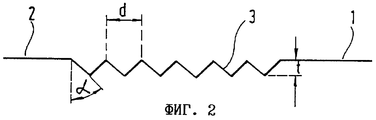
На фиг.1 показан фрагмент печатной формы 1, поверхность 2 которой имеет гравировку 3 заданной глубины t, заполняемую печатной краской. Показанные в поперечном сечении выгравированные элементы имеют вид линий, проходящих перпендикулярно плоскости чертежа, и выполнены таким образом, что между параллельно проходящими углублениями остаются перегородки 4, верхний край 5 которых расположен на уровне поверхности 2 печатной формы. Перегородки 4, с одной стороны, предотвращают удаление печатной краски в процессе стирания из образованных гравировкой 3 углублений, а с другой стороны, обеспечивают структурирование переносимого на основу красочного слоя, т.е. придают ему рельефность. На участке гравировки поверхность основы полностью запечатывается краской.Figure 1 shows a fragment of the
Шаг между параллельно проходящими элементами гравировки 3 соответствует расстоянию d между верхними краями 5 перегородок. В показанном на фиг.1-3 варианте, когда шаг, на который в процессе гравирования углублений смещается гравировальный инструмент, соответствует расстоянию d между верхними краями перегородок, это расстояние d предпочтительно составляет от 20 до 150 мкм, при этом для получения тонкой, мелкой структуры, которую невозможно различить без помощи дополнительных вспомогательных средств, расстояние примерно в 50 мкм является наиболее предпочтительным.The step between parallel passing
Получаемое за счет перегородок упорядоченное или периодическое изменение толщины красочного слоя позволяет создать в напечатанном красочном слое мелкую структуру, которую с учетом разрешающей способности человеческого глаза невозможно различить невооруженным глазом при обычном рассмотрении и которая поэтому может служить скрытым защитным элементом или признаком, не воспроизводимым ни электрофотографическим, ни каким-либо иным способом печатания.The ordered or periodic change in the thickness of the ink layer obtained by the partitions makes it possible to create a fine structure in the printed ink layer, which, given the resolution of the human eye, cannot be distinguished with the naked eye during normal viewing, and which therefore can serve as a hidden protective element or sign that cannot be reproduced either by electrophotographic, nor in any other way of printing.
Несмотря на наличие в напечатанном красочном слое мелкой структуры, он воспринимается человеческим глазом как однородное красочное покрытие. Интенсивность цветового ощущения, соответственно воспринимаемый цветовой тон или оттенок зависят от средней толщины красочного слоя, и их при заданном угле α наклона боковых поверхностей выгравированных элементов можно регулировать изменением глубины t гравировки.Despite the presence of a fine structure in the printed ink layer, it is perceived by the human eye as a uniform ink coating. The intensity of the color sensation, respectively, the perceived color tone or hue depends on the average thickness of the paint layer, and for a given angle α of inclination of the side surfaces of the engraved elements can be controlled by changing the engraving depth t.
На фиг.2 в сечении показана печатная форма, которая позволяет печатать в среднем более тонкий красочный слой, создающий более светлый цветовой тон. Гравированные поверхности показанных на фиг.1 и 2 печатных форм имеют одинаковые размеры при одном и том же угле α наклона боковых поверхностей элементов гравировки 3. За счет меньшей глубины t гравировки на фиг.2 расстояние d между выгравированными линиями выбрано меньшим. При печатании взаимосвязанных сплошных запечатанных поверхностей важно с учетом угла α наклона боковых поверхностей элементов гравировки выбирать такую глубину t гравировки и такое расстояние d между верхними краями 5 перегородок, чтобы внутри выгравированного участка на уровне поверхности 2 печатной формы не образовывались плоские площадки.Figure 2 is a cross-sectional view of a printing plate that allows an average print of a thinner ink layer, creating a lighter color tone. The engraved surfaces of the printing forms shown in FIGS. 1 and 2 have the same dimensions at the same angle α of inclination of the side surfaces of the
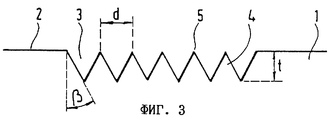
На фиг.3 гравированная поверхность имеет ту же протяженность, что и в примерах, показанных на фиг.1 и 2. При этом гравировка имеет ту же глубину t, что и на фиг.1. Хотя перегородки 4 и имеют другой угол β наклона их боковых поверхностей, средняя толщина переносимого с показанной на фиг.3 печатной формы красочного слоя соответствует толщине слоя, напечатанного с помощью печатной формы, показанной на фиг.1. Несмотря на различное расстояние d между перегородками 5, а тем самым и на различную мелкую или высоколиниатурную структуру поверхности, запечатываемые с помощью показанных на фиг.1 и 3 печатных форм, имеют одинаковый цветовой тон.In Fig. 3, the engraved surface has the same length as in the examples shown in Figs. 1 and 2. Moreover, the engraving has the same depth t as in Fig. 1. Although the partitions 4 have a different inclination angle β of their side surfaces, the average thickness of the ink layer transferred from the printing form shown in FIG. 3 corresponds to the thickness of the layer printed using the printing form shown in FIG. 1. Despite the different distance d between the
В отличие от этого печатные формы, показанные на фиг.2 и 3, имеют одинаковое расстояние d между перегородками и поэтому позволяют воспроизводить мелкую структуру с одинаковой периодичностью элементов, однако из-за различных углов (α, β) наклона боковых поверхностей гравированных элементов напечатанные с их помощью красочные слои различаются средней толщиной и оттенком.In contrast, the printing forms shown in FIGS. 2 and 3 have the same distance d between the partitions and therefore allow reproducing a fine structure with the same periodicity of elements, however, due to different angles (α, β) of the inclination of the side surfaces of the engraved elements, printed with with their help, the colorful layers vary in average thickness and hue.
Гравировку 3 предпочтительно выполняют вращающимися штихелями, угол при вершине которых, измеренный относительно средней линии штихеля, соответствует углу наклона боковых поверхностей элементов гравировки. Эти углы наклона предпочтительно составляют от 15 до 60°, более предпочтительно от 30 до 50°. Механические гравировальные инструменты, прежде всего с указанными предпочтительными значениями угла при их вершине, отличаются повышенной стойкостью. Печатные формы с предпочтительными углами наклона боковых поверхностей элементов гравировки, соответственно перегородок, более просто размножать путем изготовления вторичных форм, а с точки зрения техники печатания они, кроме того, обладают наиболее высокими свойствами. Перегородкам наиболее предпочтительно придавать клиновидную (в сечении) форму, соответственно профиль. Однако можно использовать и профили любой другой формы, в частности волнообразный или синусоидальный профиль. Форма поперечного сечения перегородок 4 ограничена только возможностями придания гравировальному инструменту необходимого внешнего контура.
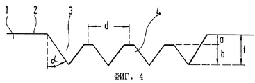
При необходимости уменьшить лишь толщину красочного слоя на участке перехода от одной линии мелкой структуры к соседней до значения, отличного от нуля, для этой цели пригодны структуры, показанные на фиг.4 и 5.If necessary, reduce only the thickness of the paint layer at the transition from one line of the fine structure to the neighboring one to a value other than zero, the structures shown in FIGS. 4 and 5 are suitable for this purpose.
Оригинальную форму для матрицирования или печатный шаблон, показанный на фиг.4, изготавливают, удаляя после гравирования образующих мелкую структуру углублений материал с обращенных наружу концов перегородок. В другом варианте сначала можно также снять материал на всем гравируемом участке на глубину а, а затем выгравировать образующие мелкую структуру углубления. В результате обращенные наружу концы перегородок оказываются расположенными ниже уровня поверхности 2 печатной формы на величину а. Остаточная высота перегородок, называемая ниже амплитудой b, представляет собой разность между глубиной t гравировки и величиной а уменьшения высоты перегородок. Запечатанная с использованием подобной печатной формы основа имеет на участке гравировки покрывающий ее поверхность сплошной красочный слой толщиной а, дополнительно "модулированный" мелкой структурой максимальной амплитуды b. Выполненные в рассматриваемом примере в виде плоских площадок верхние концы перегородок оставляют на оттиске тонкие светлые линии. При соответствующем прохождении образующих перегородки 4 гравированных линий светлые линии, оставляемые на оттиске трапециевидными перегородками 4, могут воспроизводить рисунки, шрифтовые знаки или графические символы.The original mold for matrixing or the printing template shown in Fig. 4 is made by removing material from the outwardly facing ends of the partitions after engraving forming a fine structure of the recesses. In another embodiment, you can also first remove the material on the entire engraved area to a depth of a, and then engrave the depressions forming the fine structure. As a result, the outwardly facing ends of the partitions are located below the level of the
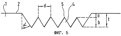
В показанном на фиг.5 варианте уменьшить высоту перегородок на величину а можно также, выбрав при заданном угле α наклона боковых поверхностей и при заданной глубине t гравировки расстояние между отдельными гравированными линиями настольно малым, чтобы верхний край 5 перегородок располагался ниже уровня поверхности 2 печатной формы.In the embodiment shown in FIG. 5, it is possible to reduce the height of the partitions by a value as well, by choosing for a given angle α of inclination of the side surfaces and for a given engraving depth t, the distance between the individual engraved lines is so small that the
Преимущество, связанное с уменьшением высоты перегородок, состоит в том, что пластмассовая поверхность стирающего валика не контактирует непосредственно с имеющими острые края перегородками 4, благодаря чему снижаются истирание и износ не только поверхности самого стирающего валика, но и мелких гравированных структур печатной формы. Величина а, на которую высота перегородок уменьшена относительно уровня поверхности 2 печатной формы, предпочтительно составляет от 2 до 5 мкм. С целью обеспечить четкое воспроизведение гравировки в виде мелкой структуры перенесенного на основу красочного слоя амплитуда b должна составлять более 50% от глубины t гравировки.The advantage associated with reducing the height of the partitions is that the plastic surface of the erasing roller does not directly contact the sharp-edged partitions 4, thereby reducing the abrasion and wear of not only the surface of the erasing roller itself, but also of small engraved printed form structures. The value of a, by which the height of the partitions is reduced relative to the level of the
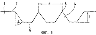
На фиг.6 показан еще один вариант предлагаемой в изобретении гравировки, дополненной перегородками. В этом варианте перегородки 4 расположены на большем расстоянии d друг от друга. В отличие от вариантов выполнения по фиг.1-5 расстояние d между перегородками не соответствует в данном случае интервалу, на который в процессе гравирования углублений смещается гравировальный инструмент. Расстояние d предпочтительно составляет менее 500 мкм. Между перегородками 4 предусмотрены горизонтальные донные участки 6 гравировки, которым для более эффективного удержания краски целенаправленно придана заданная шероховатость. Такую шероховатость поверхности задают путем подбора соответствующих геометрических параметров гравировального инструмента, а именно угла при его вершине и радиуса округления его вершины, а также путем задания соответствующих значений, определяющих его смещение при переходе от одной гравируемой линии к другой в направлении, поперечном направлению гравирования.Figure 6 shows another variant proposed in the invention of engraving, supplemented by partitions. In this embodiment, the partitions 4 are located at a greater distance d from each other. In contrast to the embodiments of FIGS. 1-5, the distance d between the partitions does not correspond in this case to the interval by which the engraving tool is shifted during the engraving of the recesses. The distance d is preferably less than 500 microns. Between the partitions 4, horizontal bottom sections 6 of the engraving are provided, to which, for more effective retention of the paint, a predetermined roughness is purposefully given. This surface roughness is set by selecting the appropriate geometric parameters of the engraving tool, namely the angle at its top and the radius of rounding of its top, as well as by setting the corresponding values that determine its displacement when moving from one engraved line to another in the direction transverse to the direction of engraving.
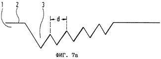
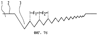
В соответствии с одним из предпочтительных вариантов осуществления изобретения гравировку 3 наносят на поверхность 2 печатной формы таким образом, чтобы ее глубина в пределах гравированной поверхности была не постоянной, а непрерывно увеличивалась, соответственно уменьшалась в одном из направлений (фиг.7а, 7б). При изготовлении гравировки переменной глубины самые нижние точки каждой гравированной линии предпочтительно располагать в плоскости, которая проходит наклонно к поверхности печатной формы. Глубину гравировки можно также изменять таким образом, чтобы самые нижние в плоскости поперечного сечения печатной формы точки лежали на кривой, форму которой можно описать, например, с помощью параболы или гиперболы. Изменение глубины гравировки позволяет варьировать воспринимаемый цветовой тон, соответственно оттенок в пределах взаимосвязанной сплошной запечатанной поверхности и прежде всего в тех случаях, когда глубина гравировки изменяется на величину в пределах от 5 до 60 мкм.In accordance with one of the preferred embodiments of the invention,
В показанном на фиг.7а варианте расстояние d между перегородками и их высота постоянны на всем гравированном участке, тогда как в показанном на фиг.7б варианте расстояние между перегородками и их высота увеличиваются с возрастанием глубины гравировки (d1>d2).In the embodiment shown in FIG. 7a, the distance d between the partitions and their height are constant over the entire engraved area, while in the embodiment shown in FIG. 7b, the distance between the partitions and their height increase with increasing engraving depth (d 1 > d 2 ).
Существует также возможность комбинировать на одной печатной форме элементы гравировки различного типа и формы, а также перегородки различной формы. Равным образом гравировку различных типов или перегородки различной формы можно выполнять на смежных участках поверхности или же соответствующим образом варьировать эти их параметры в пределах одного замкнутого участка гравированной поверхности. Кроме того, на первую гравировку можно накладывать вторую. При выполнении первой, а также второй гравировки в виде параллельных, предпочтительно прямых, гравированных линий образуется так называемый растр с перекрещивающимися линиями. Если линии первой гравировки пересекают линии второй гравировки по углом от 20 до 90°, прежде всего от 40 до 70°, то в этом случае достигается наиболее эффективное удержание краски получаемой в результате гравировкой, что положительно сказывается на важных с точки зрения техники печатания свойствах соответствующим образом выгравированной печатной формы. Кроме того, отпечатанные с помощью подобных печатных форм красочные слои отличаются наиболее равномерным цветовым тоном.It is also possible to combine engraving elements of various types and shapes on one printed form, as well as partitions of various shapes. Similarly, engraving of various types or partitions of various shapes can be performed on adjacent surface areas, or their parameters can be varied accordingly within one closed area of the engraved surface. In addition, the second engraving can be applied to the second. When performing the first as well as the second engraving in the form of parallel, preferably straight, engraved lines, a so-called raster with intersecting lines is formed. If the lines of the first engraving intersect the lines of the second engraving at an angle from 20 to 90 °, primarily from 40 to 70 °, then in this case the most effective retention of the ink resulting from the engraving is achieved, which positively affects the relevant properties from the point of view of printing technology image engraved printing plate. In addition, the colorful layers printed using such printing plates are distinguished by the most uniform color tone.
Первую и наложенную на нее вторую гравировку можно получать гравировальными инструментами различной формы, а также гравированием на различную глубину и/или с различным шагом между гравированными линиями. В случае предпочтительного растра с перекрещивающимися линиями такая гравировка позволяет получить периодически прерывающиеся перегородки.The first and second engraving superimposed on it can be obtained by engraving tools of various shapes, as well as engraving to various depths and / or with different steps between the engraved lines. In the case of a preferred raster with intersecting lines, such engraving allows you to get periodically interrupted partitions.
Claims (71)
Applications Claiming Priority (2)
| Application Number | Priority Date | Filing Date | Title |
|---|---|---|---|
| DE19845440.6 | 1998-10-02 | ||
| DE19845440A DE19845440A1 (en) | 1998-10-02 | 1998-10-02 | Intaglio printing process for full-surface printing of large areas |
Publications (2)
| Publication Number | Publication Date |
|---|---|
| RU2001111870A RU2001111870A (en) | 2003-06-10 |
| RU2230667C2 true RU2230667C2 (en) | 2004-06-20 |
Family
ID=7883207
Family Applications (1)
| Application Number | Title | Priority Date | Filing Date |
|---|---|---|---|
| RU2001111870/12A RU2230667C2 (en) | 1998-10-02 | 1999-09-29 | Printing plate for compact printing of large area surfaces, method for its manufacture, information carrier with large-area printed image and method for metallographic printing |
Country Status (18)
| Country | Link |
|---|---|
| US (2) | US6811858B1 (en) |
| EP (1) | EP1119457B2 (en) |
| JP (2) | JP4392779B2 (en) |
| CN (1) | CN1159152C (en) |
| AR (1) | AR020890A1 (en) |
| AT (1) | ATE228932T1 (en) |
| AU (1) | AU755233B2 (en) |
| CA (1) | CA2345227C (en) |
| DE (2) | DE19845440A1 (en) |
| DK (1) | DK1119457T3 (en) |
| ES (1) | ES2188246T3 (en) |
| PL (1) | PL190716B1 (en) |
| PT (1) | PT1119457E (en) |
| RU (1) | RU2230667C2 (en) |
| TR (1) | TR200100908T2 (en) |
| UA (1) | UA70969C2 (en) |
| WO (1) | WO2000020217A1 (en) |
| ZA (1) | ZA200102253B (en) |
Families Citing this family (39)
| Publication number | Priority date | Publication date | Assignee | Title |
|---|---|---|---|---|
| DE10044711A1 (en) * | 2000-09-08 | 2002-03-21 | Giesecke & Devrient Gmbh | value document |
| DE10162050A1 (en) * | 2001-12-17 | 2003-07-03 | Giesecke & Devrient Gmbh | value document |
| DE10201032A1 (en) * | 2002-01-11 | 2003-07-24 | Giesecke & Devrient Gmbh | Steel intaglio printing process for producing a security document, as well as steel intaglio printing plate and semi-finished products therefor, and process for their production |
| EP1369230A1 (en) | 2002-06-05 | 2003-12-10 | Kba-Giori S.A. | Method of manufacturing an engraved plate |
| GB0218765D0 (en) * | 2002-08-12 | 2002-09-18 | Rue De Int Ltd | Gravure printing plate |
| EP1393925A1 (en) | 2002-09-02 | 2004-03-03 | Kba-Giori S.A. | Smooth cut printing plate |
| DE10328744A1 (en) * | 2003-06-25 | 2005-01-13 | Metronic Ag | Print carrier with optically birefringent layer |
| AT504185B1 (en) | 2003-07-03 | 2009-06-15 | Oebs Gmbh | METHOD FOR PRODUCING A PRESSURE PLATE |
| WO2005106586A1 (en) * | 2004-04-29 | 2005-11-10 | Hueck Folien Gmbh & Co. Kg | Method for relief-printing highly conductive paths onto conducting substrates |
| JP2005343134A (en) * | 2004-06-07 | 2005-12-15 | Nippon Decor Inc | Photogravure plate |
| EP1755892A1 (en) | 2004-06-14 | 2007-02-28 | Hueck Folien GmbH & Co. KG | Seamless 2d or 3d surface structures on rotary embossing dies for uv casting methods |
| DE102005008135A1 (en) * | 2005-02-21 | 2006-08-31 | Giesecke & Devrient Gmbh | Disk with halftone image |
| DK1832433T3 (en) * | 2006-03-07 | 2012-01-16 | Amcor Flexibles Kreuzlingen | Method and embossing for printing a printing material |
| EP1837202B1 (en) | 2006-03-21 | 2013-02-27 | Hueck Folien Ges.m.b.H. | Method for manufacturing a seamless embossing cylinder |
| DE102006016118A1 (en) | 2006-04-04 | 2007-10-11 | Giesecke & Devrient Gmbh | security element |
| DE102006029852A1 (en) * | 2006-06-27 | 2008-01-03 | Giesecke & Devrient Gmbh | Method of applying a microstructure, mold and microstructured article |
| JP2008023997A (en) * | 2006-07-20 | 2008-02-07 | Heidelberger Druckmas Ag | Method for forming falsification prevention means on printing plate |
| US7889396B2 (en) * | 2006-10-20 | 2011-02-15 | Great Computer Corporation | Engraving method for a laser engraver |
| KR100918814B1 (en) * | 2007-10-04 | 2009-09-25 | 건국대학교 산학협력단 | High speed method for manufacturing ceramic electronic component used by printing method |
| JP5500716B2 (en) * | 2010-02-17 | 2014-05-21 | 富士フイルム株式会社 | Relief manufacturing apparatus and relief manufacturing method |
| KR20130094685A (en) * | 2010-08-05 | 2013-08-26 | 가부시키가이샤 씽크. 라보라토리 | Gravure printing plate and method for producing gravure printing plate |
| JP5760363B2 (en) * | 2010-09-30 | 2015-08-12 | 凸版印刷株式会社 | Screen printing apparatus and printing method therefor |
| KR20120061424A (en) * | 2010-12-03 | 2012-06-13 | 한국전자통신연구원 | Intaglio Printing Plate Including Supplementary Pattern And Method For Fabricating The Same |
| DE102011107154A1 (en) * | 2011-07-14 | 2013-01-17 | Giesecke & Devrient Gmbh | Optically variable element, in particular security element for a data carrier |
| DE102011121763B4 (en) | 2011-12-21 | 2023-04-06 | Volkswagen Aktiengesellschaft | Method for displaying distance information on a display device of a vehicle and display device |
| CN104608471B (en) * | 2013-11-01 | 2017-09-12 | 上海英内物联网科技股份有限公司 | A kind of gravure printing roller and its manufacture method |
| DE102015009786A1 (en) | 2015-07-27 | 2017-02-02 | Giesecke & Devrient Gmbh | Embossing tool for producing a security element with an optically variable structure |
| KR102113903B1 (en) * | 2015-08-26 | 2020-05-21 | 주식회사 엘지화학 | Method for manufacturing cliche for offset printing and cliche for offset printing |
| JP6552645B2 (en) * | 2015-12-28 | 2019-07-31 | シャープ株式会社 | Printing intaglio, method of producing printing intaglio, method of producing printed matter, and printed matter |
| CN106515192A (en) * | 2016-09-30 | 2017-03-22 | 中山松德印刷机械有限公司 | Solvent-free intaglio printing plate |
| CN106515212A (en) * | 2016-09-30 | 2017-03-22 | 中山松德印刷机械有限公司 | Novel solvent-free intaglio printing technology and printing machine for same |
| AU2018271142A1 (en) | 2017-05-17 | 2020-01-16 | Ccl Secure Pty Ltd | A banknote and a method of producing a plurality of banknotes and a print press for producing a plurality of banknotes |
| EP3421255A1 (en) | 2017-06-29 | 2019-01-02 | Gemalto Sa | Data carrier with tactile printed area for ink writing data |
| CN109246950B (en) * | 2018-09-30 | 2020-09-11 | 信利光电股份有限公司 | Manufacturing method of cover plate with gradually changed colors, cover plate and electronic equipment |
| JP7008651B2 (en) * | 2019-02-04 | 2022-01-25 | ユニバーサル製缶株式会社 | Bottle cans and their manufacturing methods |
| TWI748696B (en) * | 2019-11-18 | 2021-12-01 | 德商博斯特比勒費爾德有限公司 | Method for determining print parameters of a printing machine and test stand |
| CN113840468B (en) * | 2020-06-08 | 2023-09-08 | 哈尔滨工业大学(威海) | Screen printing three-dimensional surface conformal circuit manufacturing method based on curved surface partition |
| AT523951B1 (en) * | 2020-06-18 | 2023-03-15 | Oesterreichische Banknoten Und Sicherheitsdruck Gmbh | PROCEDURE FOR ENGRAVING AN INTAGLIO GRAPHIC PLATE |
| EP4159463A1 (en) * | 2021-10-04 | 2023-04-05 | Hueck Folien Gesellschaft m.b.H. | Gravure printing cylinder for microprinting |
Family Cites Families (23)
| Publication number | Priority date | Publication date | Assignee | Title |
|---|---|---|---|---|
| US2322530A (en) † | 1939-06-14 | 1943-06-22 | Charles J Macarthur | Intaglio printing |
| US2210923A (en) † | 1939-07-10 | 1940-08-13 | Jacquerod | Process of graining intaglio and gravure printing plates |
| GB866070A (en) † | 1956-03-19 | 1961-04-26 | Kemitype Ltd | Improvements in or relating to printing elements |
| BE648864A (en) † | 1963-12-06 | 1964-10-01 | ||
| DE6601350U (en) * | 1968-03-22 | 1969-03-06 | Philips Gmbh | Gravure printing ink carrier for powdered printing inks |
| US3980018A (en) * | 1970-07-03 | 1976-09-14 | Director General, Printing Bureau, Ministry Of Finance | Special intaglio printing process for preventing forgery of securities |
| CH585624A5 (en) † | 1973-12-21 | 1977-03-15 | Sicpa Holding Sa | |
| CH581543A5 (en) * | 1974-07-30 | 1976-11-15 | De La Rue Giori Sa | |
| JPS5333705A (en) * | 1976-09-09 | 1978-03-29 | Daido Maruta Finishing | Engraving roll for textile printing and photogravure printing |
| GB2030929B (en) * | 1978-09-15 | 1982-11-24 | Crosfield Electronics Ltd | Gravure printing formes |
| CH662989A5 (en) † | 1983-11-16 | 1987-11-13 | De La Rue Giori Sa | VALUE PAPER. |
| US4715623A (en) * | 1984-09-28 | 1987-12-29 | American Bank Note Company | Documents having a revealable concealed identifier and the method of making such documents |
| JP2539267B2 (en) * | 1989-07-03 | 1996-10-02 | 株式会社シンク・ラボラトリー | Method of forming plate characters in mesh gravure plate making method |
| JPH0373391A (en) † | 1989-08-14 | 1991-03-28 | Toppan Printing Co Ltd | Printing intaglio structure |
| JP3374439B2 (en) * | 1993-05-10 | 2003-02-04 | 株式会社村田製作所 | Gravure printing plate |
| US5675420A (en) * | 1995-01-23 | 1997-10-07 | Ohio Electronic Engravers, Inc. | Intaglio engraving method and apparatus |
| JPH08282195A (en) | 1995-04-12 | 1996-10-29 | Hokubu Tsushin Kogyo Kk | Character engraving device |
| DE19624131A1 (en) * | 1996-06-17 | 1997-12-18 | Giesecke & Devrient Gmbh | Process for the production of embossing plates |
| JP3026164B2 (en) † | 1996-08-08 | 2000-03-27 | 大日本印刷株式会社 | Gravure fine line printing plate and printed matter |
| JP3504074B2 (en) * | 1996-08-21 | 2004-03-08 | 独立行政法人 国立印刷局 | Direct engraving method for line drawings |
| JPH10250249A (en) † | 1997-03-10 | 1998-09-22 | Mitsubishi Electric Corp | Original plate for pad printing and manufacture thereof |
| JPH11221973A (en) * | 1998-02-06 | 1999-08-17 | Dainippon Printing Co Ltd | Gravure printing plate |
| JPH11221974A (en) * | 1998-02-06 | 1999-08-17 | Dainippon Printing Co Ltd | Gravure printing plate |
-
1998
- 1998-10-02 DE DE19845440A patent/DE19845440A1/en not_active Ceased
-
1999
- 1999-09-29 ES ES99947434T patent/ES2188246T3/en not_active Expired - Lifetime
- 1999-09-29 CN CNB998105929A patent/CN1159152C/en not_active Expired - Fee Related
- 1999-09-29 US US09/787,920 patent/US6811858B1/en not_active Expired - Fee Related
- 1999-09-29 WO PCT/EP1999/007217 patent/WO2000020217A1/en active IP Right Grant
- 1999-09-29 TR TR2001/00908T patent/TR200100908T2/en unknown
- 1999-09-29 UA UA2001053028A patent/UA70969C2/en unknown
- 1999-09-29 AT AT99947434T patent/ATE228932T1/en active
- 1999-09-29 AU AU60881/99A patent/AU755233B2/en not_active Ceased
- 1999-09-29 DK DK99947434T patent/DK1119457T3/en active
- 1999-09-29 JP JP2000573554A patent/JP4392779B2/en not_active Expired - Fee Related
- 1999-09-29 RU RU2001111870/12A patent/RU2230667C2/en not_active IP Right Cessation
- 1999-09-29 DE DE59903682T patent/DE59903682D1/en not_active Expired - Lifetime
- 1999-09-29 PL PL99347154A patent/PL190716B1/en not_active IP Right Cessation
- 1999-09-29 PT PT99947434T patent/PT1119457E/en unknown
- 1999-09-29 EP EP99947434.9A patent/EP1119457B2/en not_active Expired - Lifetime
- 1999-09-29 CA CA002345227A patent/CA2345227C/en not_active Expired - Fee Related
- 1999-09-30 AR ARP990104975A patent/AR020890A1/en active IP Right Grant
-
2001
- 2001-03-19 ZA ZA200102253A patent/ZA200102253B/en unknown
-
2004
- 2004-09-21 US US10/944,848 patent/US7350461B2/en not_active Expired - Fee Related
-
2009
- 2009-07-01 JP JP2009156624A patent/JP5229964B2/en not_active Expired - Fee Related
Also Published As
| Publication number | Publication date |
|---|---|
| US7350461B2 (en) | 2008-04-01 |
| EP1119457B1 (en) | 2002-12-04 |
| ES2188246T3 (en) | 2003-06-16 |
| JP4392779B2 (en) | 2010-01-06 |
| CA2345227A1 (en) | 2000-04-13 |
| WO2000020217A1 (en) | 2000-04-13 |
| US20050056175A1 (en) | 2005-03-17 |
| PL347154A1 (en) | 2002-03-25 |
| EP1119457B2 (en) | 2014-07-23 |
| ZA200102253B (en) | 2001-12-11 |
| EP1119457A1 (en) | 2001-08-01 |
| DE59903682D1 (en) | 2003-01-16 |
| PL190716B1 (en) | 2005-12-30 |
| UA70969C2 (en) | 2004-11-15 |
| ATE228932T1 (en) | 2002-12-15 |
| JP5229964B2 (en) | 2013-07-03 |
| CN1159152C (en) | 2004-07-28 |
| PT1119457E (en) | 2003-03-31 |
| JP2009214555A (en) | 2009-09-24 |
| AR020890A1 (en) | 2002-06-05 |
| CA2345227C (en) | 2007-08-07 |
| AU6088199A (en) | 2000-04-26 |
| DE19845440A1 (en) | 2000-04-06 |
| AU755233B2 (en) | 2002-12-05 |
| TR200100908T2 (en) | 2001-08-21 |
| JP2002526290A (en) | 2002-08-20 |
| DK1119457T3 (en) | 2003-03-24 |
| CN1316952A (en) | 2001-10-10 |
| US6811858B1 (en) | 2004-11-02 |
Similar Documents
| Publication | Publication Date | Title |
|---|---|---|
| RU2230667C2 (en) | Printing plate for compact printing of large area surfaces, method for its manufacture, information carrier with large-area printed image and method for metallographic printing | |
| RU2236949C2 (en) | Data carrier, printing plate, method for manufacturing the form and metallographic printing method for sealing adjacent surfaces with continuous paint layers of different thickness | |
| EP1748900B1 (en) | Intaglio printing plate | |
| RU2244632C2 (en) | Information medium sealed up by method of metallographic printing | |
| RU2183558C2 (en) | Stamp manufacture method | |
| RU2001111870A (en) | Method of metallographic printing for continuous sealing of surfaces of a large area | |
| RU2324599C2 (en) | Important document | |
| CN1056341C (en) | Printing plate | |
| RU2001111865A (en) | Method of metallographic printing for sealing adjacent surfaces with solid colorful layers of various thicknesses | |
| PL199462B1 (en) | Gravure printing plate and valuable document produced by the same | |
| EP0398267B1 (en) | Gravure printing plate | |
| RU2003109429A (en) | PRINTING FORM FOR METALLOGRAPHIC PRINTING AND A VALUABLE DOCUMENT MADE WITH HELP OF IT | |
| RU2010114849A (en) | DATA CARRIER EQUIPPED BY A DRAWING EXECUTED BY METAL PRINTING | |
| JP2004066579A (en) | Intaglio printing plate, its manufacturing method, and intalgio printed matter using the printing plate | |
| JP6060830B2 (en) | Special latent image pattern former | |
| JP2009119790A (en) | Image card | |
| US20060152770A1 (en) | Gravure printing |
Legal Events
| Date | Code | Title | Description |
|---|---|---|---|
| MM4A | The patent is invalid due to non-payment of fees |
Effective date: 20130930 |