RU2209373C1 - Burner apparatus - Google Patents
Burner apparatus Download PDFInfo
- Publication number
- RU2209373C1 RU2209373C1 RU2002120586A RU2002120586A RU2209373C1 RU 2209373 C1 RU2209373 C1 RU 2209373C1 RU 2002120586 A RU2002120586 A RU 2002120586A RU 2002120586 A RU2002120586 A RU 2002120586A RU 2209373 C1 RU2209373 C1 RU 2209373C1
- Authority
- RU
- Russia
- Prior art keywords
- fuel
- nozzle
- combustion chamber
- annular substrate
- air
- Prior art date
Links
- 239000000446 fuel Substances 0.000 claims abstract description 58
- 239000007788 liquid Substances 0.000 claims abstract description 22
- 239000000758 substrate Substances 0.000 claims abstract description 16
- 238000002485 combustion reaction Methods 0.000 claims description 29
- 239000003381 stabilizer Substances 0.000 claims description 4
- 238000001704 evaporation Methods 0.000 abstract description 9
- 230000008020 evaporation Effects 0.000 abstract description 9
- 230000000694 effects Effects 0.000 abstract description 2
- 239000000126 substance Substances 0.000 abstract 1
- 238000009835 boiling Methods 0.000 description 5
- 238000000034 method Methods 0.000 description 5
- 238000005086 pumping Methods 0.000 description 5
- 230000002745 absorbent Effects 0.000 description 4
- 239000002250 absorbent Substances 0.000 description 4
- 230000005484 gravity Effects 0.000 description 4
- 239000000243 solution Substances 0.000 description 4
- 230000015572 biosynthetic process Effects 0.000 description 3
- 238000004939 coking Methods 0.000 description 3
- 238000005755 formation reaction Methods 0.000 description 3
- 238000010438 heat treatment Methods 0.000 description 3
- 238000009825 accumulation Methods 0.000 description 2
- 238000010586 diagram Methods 0.000 description 2
- 230000009931 harmful effect Effects 0.000 description 2
- 239000002184 metal Substances 0.000 description 2
- 239000000203 mixture Substances 0.000 description 2
- 239000002244 precipitate Substances 0.000 description 2
- 239000004071 soot Substances 0.000 description 2
- 238000009827 uniform distribution Methods 0.000 description 2
- 229910000831 Steel Inorganic materials 0.000 description 1
- 238000007664 blowing Methods 0.000 description 1
- 239000000571 coke Substances 0.000 description 1
- 230000007423 decrease Effects 0.000 description 1
- 238000009826 distribution Methods 0.000 description 1
- 239000002828 fuel tank Substances 0.000 description 1
- 238000002347 injection Methods 0.000 description 1
- 239000007924 injection Substances 0.000 description 1
- 239000011148 porous material Substances 0.000 description 1
- 230000002265 prevention Effects 0.000 description 1
- 239000000047 product Substances 0.000 description 1
- 238000010926 purge Methods 0.000 description 1
- 230000000717 retained effect Effects 0.000 description 1
- 229920006395 saturated elastomer Polymers 0.000 description 1
- 238000005507 spraying Methods 0.000 description 1
- 239000010959 steel Substances 0.000 description 1
- 230000001360 synchronised effect Effects 0.000 description 1
- 238000004227 thermal cracking Methods 0.000 description 1
- 239000012808 vapor phase Substances 0.000 description 1
- 238000010792 warming Methods 0.000 description 1
Images

Landscapes
- Wick-Type Burners And Burners With Porous Materials (AREA)
Abstract
Description
Изобретение относится к области энергетики, в частности горелочным устройствам, и может быть использовано в автомобильной промышленности. The invention relates to the field of energy, in particular burner devices, and can be used in the automotive industry.
Известна испарительная горелка встроенного отопителя автомобиля [1], работающая на жидком топливе. Между передней стенкой опорной конструкции для корпуса с адсорбирующей поверхностью, к которому подается горючее, и корпусом с адсорбирующей поверхностью расположен делительный диск с отверстиями, причем отверстия равномерно распределены по всей поверхности диска. Такая конструкция позволяет достичь равномерного распределения топлива на основе капиллярного эффекта между опорной конструкцией и делительным диском. Диск выполнен из стали при помощи перфорирования и имеет толщину 0,1 мм. Known vapor burner built-in heater of the car [1], operating on liquid fuel. Between the front wall of the supporting structure for a housing with an absorbent surface to which fuel is supplied, and a housing with an absorbent surface there is a dividing disk with holes, the holes being evenly distributed over the entire surface of the disk. This design allows you to achieve a uniform distribution of fuel based on the capillary effect between the supporting structure and the dividing disk. The disc is made of steel by perforation and has a thickness of 0.1 mm.
Данное устройство позволяет улучшить характеристики горения при равномерном распределении горючего и выработанного тепла через корпус с адсорбирующей поверхностью только на начальной стадии. Кроме того, при работе устройства образуются сажистые выделения, которые закоксовывают адсорбирующую поверхность делительного диска. This device allows to improve the combustion characteristics with a uniform distribution of fuel and generated heat through the housing with an absorbent surface only at the initial stage. In addition, when the device is operating, sooty precipitates are formed which coke on the absorbent surface of the dividing disk.
Наиболее близким техническим решением к предлагаемому изобретению, выбранным в качестве прототипа, является горелочное устройство [2], содержащее топочную камеру (1), с цилиндрической ограничительной стенкой по периметру, с торцевой ограничительной стенкой (2), в которой выполнено центральное отверстие с входящим коаксиально с осью в топочную камеру соплом подачи воздуха (3), воздух в которое подается завихрителем (9). С внутренней стороны цилиндрической ограничительной стенки расположена испарительная капиллярная структура (4), формирователь вихревых потоков (5), штуцер для установки свечи (6), жаровая труба (7), стабилизатор пламени (8), завихритель (9). Подача топлива в топочную камеру осуществляется через штуцер свечи (6). The closest technical solution to the proposed invention, selected as a prototype, is a burner device [2] containing a combustion chamber (1), with a cylindrical boundary wall around the perimeter, with an end boundary wall (2), in which a central hole is made with an incoming coaxially with an axis in the combustion chamber by an air supply nozzle (3), air into which is supplied by a swirl (9). An evaporative capillary structure (4), a vortex flow former (5), a fitting for installing a candle (6), a flame tube (7), a flame stabilizer (8), and a swirler (9) are located on the inner side of the cylindrical boundary wall. Fuel is supplied to the combustion chamber through the fitting of the plug (6).
Недостатком описанного выше горелочного устройства является то, что при его горизонтальном размещении часть топлива под действием силы тяжести стекает вниз, причем количество скапливающегося жидкого топлива зависит от длительности розжига. При затрудненном розжиге, характерном для очень низких температур, накопившееся топливо достигает количества, которое не успевает испариться на начальной стадии горения и переходит в состояние кипения, при котором образуются сажистые выделения, ведущие к быстрому закоксовыванию адсорбирующей поверхности испарительной капиллярной структуры. Соответственно снижается надежность работы горелочного устройства. The disadvantage of the burner device described above is that when it is horizontally placed, part of the fuel flows down by gravity, and the amount of accumulated liquid fuel depends on the duration of the ignition. With difficult ignition, which is characteristic of very low temperatures, the accumulated fuel reaches an amount that does not have time to evaporate at the initial stage of combustion and goes into a boiling state, in which sooty precipitates are formed, leading to a rapid coking of the adsorbing surface of the evaporative capillary structure. Accordingly, the reliability of the burner device decreases.
Основным условием надежной работы горелочных устройств испарительного типа является полное испарение поступающего топлива в капиллярной структуре испарительного элемента. Если же количество поступающего в топочную камеру в каждую единицу времени жидкого топлива больше, чем количество, превращенное в паровую фазу, то неиспарившаяся часть топлива стекает по стенкам камеры сгорания и в последствии закипает. При кипении жидкого топлива происходят не менее двух процессов, снижающих надежность и работоспособность горелочных устройств. Первый - "разбрызгивание" жидкости в процессе кипения. Формирующиеся капли топлива, попадая в топочную камеру, не успевают испариться и с потоком газообразных продуктов сгорания поступают в теплообменник, где осаждаются на стенках в виде сажистых образований, резко снижающих эффективность теплоотвода и, соответственно, общую теплопроизводительность отопителя с данным горелочным устройством. The main condition for reliable operation of the evaporative type burner devices is the complete evaporation of the incoming fuel in the capillary structure of the evaporator element. If the amount of liquid fuel entering the combustion chamber at each unit of time is greater than the amount converted to the vapor phase, then the unevaporated part of the fuel flows down the walls of the combustion chamber and subsequently boils. When boiling liquid fuel, at least two processes occur that reduce the reliability and performance of burner devices. The first is the "spraying" of the liquid during the boiling process. The droplets of fuel that form, getting into the combustion chamber, do not have time to evaporate and with the flow of gaseous products of combustion enter the heat exchanger, where they are deposited on the walls in the form of soot formations, which sharply reduce the heat removal efficiency and, accordingly, the overall heat output of the heater with this burner device.
В самой же камере, в зоне кипения жидкого топлива в результате термического крекинга происходит закоксовывание капиллярной структуры испарительного элемента. In the chamber itself, in the boiling zone of liquid fuel, thermal cracking results in coking of the capillary structure of the evaporation element.
Распределение жидкого топлива по капиллярной структуре испарительного элемента определяется множеством факторов, среди которых основными являются: действие капиллярных сил, сила тяжести, интенсивность испарения, вязкость, которые, в свою очередь, зависят от температуры и давления в топочной камере. The distribution of liquid fuel in the capillary structure of the evaporation element is determined by many factors, among which the main ones are: the action of capillary forces, gravity, evaporation rate, viscosity, which, in turn, depend on temperature and pressure in the combustion chamber.
Обычно рабочая часть капиллярной структуры испарительного элемента имеет форму диска, кольца или цилиндра с кольцевым дном. Топливо подается в одну или несколько верхних точек и далее, под действием силы тяжести и капиллярных сил растекается по капиллярной структуре. Typically, the working part of the capillary structure of the evaporation element is in the form of a disk, ring or cylinder with an annular bottom. Fuel is supplied to one or several upper points and further, under the influence of gravity and capillary forces, it flows along the capillary structure.
Капиллярная структура за счет капиллярных сил способна удержать в своих пределах определенное количество топлива. Это количество зависит от характеристик самой капиллярной структуры (для металловойлока определяющими параметрами являются диаметр проволоки, размер пор, величина смачиваемости и т.д.), удельного веса и вязкости топлива. Изменение условий и, прежде всего, температуры и давления в топочной камере существенным образом влияет на скорость испарения и течения жидкого топлива. Соответственно, при поступлении количества топлива, большего, чем способна удержать капиллярная структура, часть топлива стекает к нижней точке топочной камеры, образуя "лужу", которая при разогреве камеры начинает кипеть, вызывая отмеченные вредные последствия. The capillary structure due to capillary forces is able to keep within its limits a certain amount of fuel. This amount depends on the characteristics of the capillary structure itself (for metal metal, the determining parameters are wire diameter, pore size, wettability, etc.), specific gravity and viscosity of the fuel. Changes in conditions and, above all, temperature and pressure in the combustion chamber significantly affect the rate of evaporation and flow of liquid fuel. Accordingly, upon receipt of a quantity of fuel greater than the capillary structure is capable of retaining, part of the fuel flows to the lower point of the combustion chamber, forming a “puddle” that begins to boil upon heating of the chamber, causing the noted harmful effects.
При использовании для розжига горелочного устройства свеч накаливания необходимо обеспечить в области раскаленной поверхности свечи достаточное количество топлива для образования горючей смеси. When using glow plugs for ignition of the burner device, it is necessary to provide a sufficient amount of fuel in the area of the glowing surface of the candle to form a combustible mixture.
Поскольку процесс образования устойчивого пламени осуществляется в течение достаточно длительного времени, которое в случае повторных запусков еще больше увеличивается, то существует высокая вероятность стекания к нижним точкам топочной камеры значительного количества жидкого топлива, которое не может быть удержано в капиллярной структуре испарительного элемента. Since the process of formation of a stable flame is carried out for a sufficiently long time, which in the case of repeated starts increases even more, there is a high probability of a significant amount of liquid fuel draining to the lower points of the combustion chamber, which cannot be retained in the capillary structure of the evaporation element.
Для предотвращения вредных последствий кипения жидкого топлива необходимо устранить возможность скапливания жидкого топлива в нижних точках топочной камеры. Поскольку возможности уменьшения подачи топлива на стадии розжига ограничены условиями надежного воспламенения, то предотвращение накапливания жидкого топлива может быть достигнуто за счет откачивания стекающих с капиллярной структуры излишков жидкого топлива. При этом возможны два варианта. В первом стекающие излишки топлива выводятся из топочной камеры. Для этого требуется дополнительный топливный насос, дополнительный топливопровод для слива откачиваемого из топливной камеры топлива, дополнительный топливный бачок, что неизбежно усложнит конструкцию и процесс эксплуатации горелочного устройства и снизит надежность работы отопителей, использующих подобные горелочные устройства. To prevent the harmful effects of boiling liquid fuel, it is necessary to eliminate the possibility of accumulation of liquid fuel at the lower points of the combustion chamber. Since the possibility of reducing the fuel supply at the ignition stage is limited by the conditions of reliable ignition, the prevention of accumulation of liquid fuel can be achieved by pumping excess liquid fuel flowing from the capillary structure. In this case, two options are possible. In the first, the draining excess fuel is removed from the combustion chamber. This requires an additional fuel pump, an additional fuel line for draining the fuel pumped out of the fuel chamber, an additional fuel tank, which will inevitably complicate the design and operation of the burner device and reduce the reliability of the operation of heaters using similar burner devices.
Однако в ряде случаев при использовании топлива с малой вязкостью и при условии повышенной влажности, когда возможны срывы пламени с многократным повторением процесса розжига, вывод излишков топлива из камеры может оказаться необходимым для обеспечения работоспособности горелочного устройства. However, in some cases, when using fuel with a low viscosity and subject to increased humidity, when flame outages are possible with repeated repetition of the ignition process, the removal of excess fuel from the chamber may be necessary to ensure the operation of the burner device.
Другим возможным решением является перекачка излишков топлива обратно в капиллярную структуру испарительного элемента. При условии, что скорость перекачки топлива больше, чем скорость стекания, - это обеспечивает существенное увеличение количества топлива, находящегося внутри капиллярной структуры. Another possible solution is to transfer the excess fuel back into the capillary structure of the evaporator element. Provided that the fuel transfer rate is greater than the runoff speed, this provides a significant increase in the amount of fuel inside the capillary structure.
Достоинством такого решения является то, что оно может быть достигнуто без вывода топлива из топочной камеры. Для этой цели может быть использована энергия небольшой части воздушного потока, вводимого в топочную камеру посредством сопла подачи воздуха. С учетом характерной высокой скорости закрученного в сопле потока воздуха естественным является организация процесса перекачки стекающего жидкого топлива по принципам функционирования струйных насосов. The advantage of this solution is that it can be achieved without removing fuel from the combustion chamber. For this purpose, the energy of a small part of the air stream introduced into the combustion chamber by means of an air supply nozzle can be used. Given the characteristic high speed of the air flow swirling in the nozzle, it is natural to organize the process of pumping the flowing liquid fuel according to the principles of functioning of jet pumps.
Техническим результатом предлагаемого изобретения является повышение надежности работы горелочного устройства. The technical result of the invention is to increase the reliability of the burner device.
Технический результат достигается тем, что в горелочное устройство, содержащее топочную камеру с цилиндрической ограничительной стенкой по периметру, с торцевой ограничительной стенкой, в которой выполнено центральное отверстие, с входящим коаксиально с осью в топочную камеру соплом подачи воздуха, на боковой поверхности которого выполнено не менее двух рядов разнесенных по высоте сопла одинаковых по количеству и симметрично размещенных продольных щелевых отверстий, завихритель потока воздуха, формирователь вихревых потоков, расположенный между соплом подачи воздуха и испарительной капиллярной структурой, размещенной как на цилиндрической, так и на торцевой ограничительных стенках топочной камеры, штуцер для установки свечи, жаровую трубу и стабилизатор пламени, дополнительно введена кольцевая подложка, по внутреннему диаметру газоплотно примыкающая к соплу подачи воздуха, а по внешнему соприкасающаяся с цилиндрической ограничительной стенкой, в кольцевой подложке со стороны, примыкающей к торцевой ограничительной стенке топочной камеры, выполнены дугообразная полость и криволинейный канал, соединенный с внутренней полостью сопла подачи воздуха посредством отверстия, выполненного на боковой поверхности сопла подачи воздуха, криволинейный канал проходит вдоль нижней точки внешней торцевой поверхности подложки в области стекания жидкого топлива до дугообразной полости, в стенке, отделяющей дугообразную полость от испарительной капиллярной структуры, выполнен ряд сквозных отверстий, внутри криволинейного канала вдоль участка, проходящего через нижнюю точку кольцевой подложки относительно патрубка ввода топлива, по направлению движения воздуха газоплотно с внутренней поверхностью криволинейного канала размещено коническое сопло, в стенке кольцевой подложки, отделяющей область стекания топлива от участка внутренней полости криволинейного канала, выполнено отверстие. The technical result is achieved in that in a burner device containing a combustion chamber with a cylindrical boundary wall around the perimeter, with an end boundary wall in which a central hole is made, with an air supply nozzle entering coaxially with the axis into the combustion chamber, at least one of which has a nozzle two rows of nozzles spaced along the height of the same in number and symmetrically placed longitudinal slotted holes, an air flow swirl, a swirl flow former, Between the air supply nozzle and the evaporative capillary structure located both on the cylindrical and on the end restrictive walls of the combustion chamber, a candle fitting, a heat pipe and a flame stabilizer, an annular substrate is additionally introduced, gas-tight adjacent to the air supply nozzle in inner diameter, and externally in contact with a cylindrical restrictive wall, in an annular substrate from the side adjacent to the end restrictive wall of the combustion chamber, made arcuate the cavity and the curved channel connected to the inner cavity of the air supply nozzle by means of an opening made on the side surface of the air supply nozzle, the curved channel passes along the lower point of the outer end surface of the substrate in the region of liquid fuel runoff to the arcuate cavity, in the wall separating the arcuate cavity from evaporative capillary structure, a number of through holes are made, inside a curvilinear channel along a section passing through the lower point of the annular substrate a fuel injection nozzle in the direction of movement of air gas-tight with the inner surface of the curved channel taken conical nozzle, in the annular wall of the substrate, separates the fuel dripping from the inside cavity portion curved channel, a hole.
На фиг.1 представлен прототип предлагаемого технического решения. Figure 1 presents the prototype of the proposed technical solution.
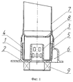
На фиг.2 представлено предлагаемое горелочное устройство. Figure 2 presents the proposed burner device.
Устройство содержит топочную камеру с цилиндрической ограничительной стенкой по периметру (1), с торцевой ограничительной стенкой (2), в которой выполнено центральное отверстие с входящим коаксиально с осью в топочную камеру соплом подачи воздуха (3), воздух в которое подается завихрителем (9). С внутренней стороны цилиндрической ограничительной стенки расположена испарительная капиллярная структура (4), формирователь вихревых потоков (5), штуцер для установки свечи (6), жаровая труба (7), стабилизатор пламени (8), кольцевая подложка (10), дугообразная полость со сквозными отверстиями (11). The device comprises a combustion chamber with a cylindrical boundary wall around the perimeter (1), with an end boundary wall (2), in which a central hole is made with an air supply nozzle (3) entering coaxially with the axis into the furnace chamber, into which air is supplied by a swirl (9) . An evaporative capillary structure (4), a vortex flow former (5), a candle fitting (6), a flame tube (7), a flame stabilizer (8), an annular substrate (10), an arcuate cavity with through holes (11).
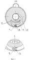
На фиг. 3 изображено сечение горелочного устройства, представленного на фиг.2, по плоскости А-А. Дугообразная полость (11), сквозные отверстия в этой полости (12), криволинейный канал (13), коническое сопло (14), отверстие для стекания жидкого топлива в полость криволинейного канала (15). In FIG. 3 shows a cross section of the burner device shown in FIG. 2 along the plane AA. An arcuate cavity (11), through holes in this cavity (12), a curved channel (13), a conical nozzle (14), an opening for draining liquid fuel into the cavity of a curved channel (15).
На фиг.4 изображена циклограмма работы горелочного устройства. Figure 4 shows the sequence diagram of the operation of the burner device.
Работа предлагаемого устройства осуществляется в соответствии с циклограммой, представленной на фиг. 4. В момент запуска t0 включается воздухонагнетающее устройство на максимальной мощности и до момента t1 осуществляется продувка топочной камеры, после чего мощность воздухонагнетающего устройства уменьшается до небольшой величины и до момента t5 (при котором регистрируется факт воспламенения) остается постоянной.The operation of the proposed device is carried out in accordance with the sequence diagram shown in FIG. 4. At the start-up time t 0, the air blower is turned on at maximum power and the furnace is purged until t 1 , after which the power of the air blower is reduced to a small amount and remains constant until t 5 (at which the ignition is detected).
После завершения продувки (момент времени t1) начинается разогрев свечи накаливания, который продолжается до момента времени t2.After the purge is completed (time t 1 ), the glow plug starts heating, which continues until time t 2 .
После разогрева свечи до максимальной температуры (момент времени t2) в момент времени t3 включается топливный насос и при средней мощности работает до момента t4.After warming up the spark plug to the maximum temperature (time t 2 ) at the time t 3, the fuel pump is switched on and at medium power it works until t 4 .
При этом происходит насыщение топливом капиллярной структуры испарительного элемента. Часть жидкого топлива удерживается в капиллярной структуре, оставшаяся стекает к нижней точке топочной камеры. Поскольку в этот период воздухонагнетательное устройство работает в режиме минимальной мощности, скорость закрученного потока в сопле подачи воздуха мала и, соответственно, мала скорость потока воздуха в криволинейном канале (13) (фиг.3), и перекачка стекающего из капиллярной структуры топлива в полость (11) практически не происходит. In this case, the capillary structure of the evaporation element is saturated with fuel. Part of the liquid fuel is held in the capillary structure, the remaining flows to the lower point of the combustion chamber. Since the air blower device operates in the minimum power mode during this period, the swirling flow rate in the air supply nozzle is small and, accordingly, the air flow velocity in the curved channel (13) is low (Fig. 3) and pumping the fuel flowing from the capillary structure into the cavity ( 11) practically does not occur.
В момент возгорания воздушной смеси происходит отключение свечи накаливания, начинается синхронное нарастание мощности воздухонагнетательного устройства и топливного насоса. Возрастание мощности воздушного потока в сопле приводит к возрастанию мощности воздушной струи из конического сопла 14 (фиг. 3) и соответствующего возрастания скорости перекачки скапливающегося в результате стекания из капиллярной структуры топлива в дугообразную полость 11 (фиг.3) и, далее, перехода его через отверстие 12 (фиг.3) обратно в капиллярную структуру. At the moment of ignition of the air mixture, the glow plug turns off, the synchronous increase in the power of the air-blowing device and the fuel pump begins. An increase in the power of the air flow in the nozzle leads to an increase in the power of the air stream from the conical nozzle 14 (Fig. 3) and a corresponding increase in the pumping rate of the fuel accumulating as a result of draining from the capillary structure into the arcuate cavity 11 (Fig. 3) and, further, its passage through hole 12 (FIG. 3) back into the capillary structure.
В результате откачивающего действия, обеспечиваемого струей воздуха, вытекающей из сопла 14 (фиг.3), к моменту полного разогрева топочной камеры все жидкое топливо оказывается в капиллярной структуре. As a result of the pumping action provided by a stream of air flowing out of the nozzle 14 (Fig. 3), by the time of the complete heating of the combustion chamber, all liquid fuel is in the capillary structure.
Отсутствие в нижних точках топочной камеры стекающего на стадии розжига жидкого топлива устраняет опасность формирования сажистых образований в теплообменнике и закоксовывание капиллярной структуры, которые возникают при кипении жидкого топлива. The absence at the lower points of the combustion chamber of liquid fuel flowing off at the stage of ignition eliminates the danger of soot formation in the heat exchanger and the coking of the capillary structure that occurs when liquid fuel boils.
ИСТОЧНИКИ ИНФОРМАЦИИ
1. Патент фирмы WEBASTO DE 4003090 С1.SOURCES OF INFORMATION
1. WEBASTO DE Patent 4003090 the company C 1.
2. Кордит Е.А. Патент РФ 2181462 "Горелочное устройство". 2. Kordit EA RF patent 2181462 "Burner device".
Claims (1)
Priority Applications (1)
| Application Number | Priority Date | Filing Date | Title |
|---|---|---|---|
| RU2002120586A RU2209373C1 (en) | 2002-08-05 | 2002-08-05 | Burner apparatus |
Applications Claiming Priority (1)
| Application Number | Priority Date | Filing Date | Title |
|---|---|---|---|
| RU2002120586A RU2209373C1 (en) | 2002-08-05 | 2002-08-05 | Burner apparatus |
Publications (1)
| Publication Number | Publication Date |
|---|---|
| RU2209373C1 true RU2209373C1 (en) | 2003-07-27 |
Family
ID=29212212
Family Applications (1)
| Application Number | Title | Priority Date | Filing Date |
|---|---|---|---|
| RU2002120586A RU2209373C1 (en) | 2002-08-05 | 2002-08-05 | Burner apparatus |
Country Status (1)
| Country | Link |
|---|---|
| RU (1) | RU2209373C1 (en) |
Cited By (1)
| Publication number | Priority date | Publication date | Assignee | Title |
|---|---|---|---|---|
| RU2427757C2 (en) * | 2009-07-24 | 2011-08-27 | Открытое акционерное общество "Элтра-Термо" | Burner device |
Citations (4)
| Publication number | Priority date | Publication date | Assignee | Title |
|---|---|---|---|---|
| GB1486128A (en) * | 1974-04-24 | 1977-09-21 | Dowa Co | Liquid fuel burner |
| FR2527743A1 (en) * | 1982-05-28 | 1983-12-02 | Toyotomi Kogyo Co Ltd | IMPROVEMENTS ON POT-TYPE OIL BURNERS |
| US5749719A (en) * | 1996-10-25 | 1998-05-12 | Rajewski; Robert Karl | Velocity sealed flare tip |
| RU2181462C1 (en) * | 2001-05-23 | 2002-04-20 | Кордит Евсей Аврумович | Burner device |
-
2002
- 2002-08-05 RU RU2002120586A patent/RU2209373C1/en not_active IP Right Cessation
Patent Citations (4)
| Publication number | Priority date | Publication date | Assignee | Title |
|---|---|---|---|---|
| GB1486128A (en) * | 1974-04-24 | 1977-09-21 | Dowa Co | Liquid fuel burner |
| FR2527743A1 (en) * | 1982-05-28 | 1983-12-02 | Toyotomi Kogyo Co Ltd | IMPROVEMENTS ON POT-TYPE OIL BURNERS |
| US5749719A (en) * | 1996-10-25 | 1998-05-12 | Rajewski; Robert Karl | Velocity sealed flare tip |
| RU2181462C1 (en) * | 2001-05-23 | 2002-04-20 | Кордит Евсей Аврумович | Burner device |
Cited By (1)
| Publication number | Priority date | Publication date | Assignee | Title |
|---|---|---|---|---|
| RU2427757C2 (en) * | 2009-07-24 | 2011-08-27 | Открытое акционерное общество "Элтра-Термо" | Burner device |
Similar Documents
| Publication | Publication Date | Title |
|---|---|---|
| FI65322C (en) | FOERFARANDE FOER FOERBRAENNING AV BRAENSLE I VAETSKEFORM SAMT EN FOERBRAENNINGSANORDNING FOER TILLAEMPNING AV FOERFARANDET | |
| KR101447715B1 (en) | Heating device including catalytic burning of liquid fuel | |
| CN108050509A (en) | Combustion furnace and method based on liquid ethanol-natural gas combined fuel | |
| RU2181462C1 (en) | Burner device | |
| EP1904789B1 (en) | Catalytic combustor and method thereof | |
| SE429062B (en) | LIQUID FUEL BURNER | |
| RU2209373C1 (en) | Burner apparatus | |
| RU2040731C1 (en) | Fuel gasification burner | |
| US3592577A (en) | Apparatus for promoting complete combustion | |
| RU2032128C1 (en) | Hot-water boiler | |
| RU2213298C1 (en) | Burner unit | |
| RU2209371C1 (en) | Burner apparatus | |
| JPH07158875A (en) | Gas hot-water supplier | |
| RU81787U1 (en) | EVAPORATOR TYPE BURNER FOR HEATER | |
| US3352345A (en) | Combustion device construction | |
| RU2799260C1 (en) | Vertical liquid oil boiler | |
| RU113336U1 (en) | BURNER | |
| RU2229062C2 (en) | Hot-bulb ignition burner | |
| RU2239128C1 (en) | Burner unit | |
| RU2800621C1 (en) | Long-burning evaporation burner | |
| SU1763806A2 (en) | Distributing manifold | |
| RU2349837C1 (en) | Chambered swirling type furnace | |
| RU2206829C1 (en) | Burner unit | |
| CN110043899A (en) | A kind of biomass carbonization gas fuel burning head | |
| RU62211U1 (en) | BURNER |
Legal Events
| Date | Code | Title | Description |
|---|---|---|---|
| MM4A | The patent is invalid due to non-payment of fees |
Effective date: 20120806 |