RU2191663C1 - Method of engagement of spur-gear toothed articles produced by electrical discharge cutting in gear trains between shafts with parallel axes - Google Patents
Method of engagement of spur-gear toothed articles produced by electrical discharge cutting in gear trains between shafts with parallel axes Download PDFInfo
- Publication number
- RU2191663C1 RU2191663C1 RU2001110989A RU2001110989A RU2191663C1 RU 2191663 C1 RU2191663 C1 RU 2191663C1 RU 2001110989 A RU2001110989 A RU 2001110989A RU 2001110989 A RU2001110989 A RU 2001110989A RU 2191663 C1 RU2191663 C1 RU 2191663C1
- Authority
- RU
- Russia
- Prior art keywords
- gear
- end surfaces
- shafts
- driven
- parallel axes
- Prior art date
Links
- 238000000034 method Methods 0.000 title claims abstract description 22
- 230000033001 locomotion Effects 0.000 claims abstract description 7
- 230000005540 biological transmission Effects 0.000 claims description 5
- 208000002925 dental caries Diseases 0.000 claims description 2
- 230000001105 regulatory effect Effects 0.000 claims description 2
- 230000036346 tooth eruption Effects 0.000 claims 1
- 230000007246 mechanism Effects 0.000 abstract description 10
- 230000000694 effects Effects 0.000 abstract description 2
- 238000011089 mechanical engineering Methods 0.000 abstract description 2
- 238000003754 machining Methods 0.000 abstract 1
- 239000000126 substance Substances 0.000 abstract 1
- 238000004519 manufacturing process Methods 0.000 description 7
- 238000010586 diagram Methods 0.000 description 2
- 239000003344 environmental pollutant Substances 0.000 description 2
- 231100000719 pollutant Toxicity 0.000 description 2
- 238000004364 calculation method Methods 0.000 description 1
- 230000008878 coupling Effects 0.000 description 1
- 238000010168 coupling process Methods 0.000 description 1
- 238000005859 coupling reaction Methods 0.000 description 1
- 238000005516 engineering process Methods 0.000 description 1
- 239000012530 fluid Substances 0.000 description 1
- 238000009434 installation Methods 0.000 description 1
- 210000003739 neck Anatomy 0.000 description 1
Images
Landscapes
- Electrical Discharge Machining, Electrochemical Machining, And Combined Machining (AREA)
Abstract
Description
Изобретение относится к области машино-, приборостроения и может быть использовано при производстве различного рода приводных механизмов передачи вращательных движений между валами с параллельными осями, в состав которых входят прямозубые изделия (ЗИ), полученные электроэрозионным вырезанием (ЭЭВ). The invention relates to the field of machinery, instrumentation and can be used in the production of various kinds of drive mechanisms for transmitting rotational movements between shafts with parallel axes, which include spur gears (ZI) obtained by electrical discharge cutting (EEE).
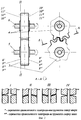
Наиболее близким способом того же назначения к заявленному изобретению по совокупности признаков является способ сопряжения прямозубых ЗИ в передачах между валами с параллельными осями, когда, независимо от метода получения и точности изготовления ЗИ, для передачи вращательного движения от ведущего вала к ведомому в конструкции механизма необходимо (фиг.1):
- обеспечить совпадение осей симметрии 1 и 2 соответственно ведущего 3 и ведомого 4 ЗИ, проходящих перпендикулярно оси вращения ведущего 5 и ведомого 6 валов;
- регламентировать величину межосевого расстояния W;
- исключить проворот ведущего 3 и ведомого 4 ЗИ относительно оси вращения соответственно ведущего 5 и ведомого 6 валов посредством, например, шпоночного соединения 7 (см. Зубчатые и червячные передачи. Некоторые вопросы кинематики, динамики, расчета и производства / Под ред. д-ра техн. наук Н. И. Колчина. Л. : Машиностроение, 1974. 352 с.; Зубчатые передачи: Справочник / Е.Г. Гинзбург, Н.Ф. Голованов, Н.Б. Фирун, Н.Т. Халебский. Под общ. ред. Е. Г. Гинзбурга. - 2-е изд., перераб. и доп. Л.: Машиностроение, 1980. 416 с.; Производство зубчатых колес: Справочник / С.Н. Колашников, А.С. Колашникова, Г.И. Коган и др. Под общ. ред. Б.А. Тайца. - 3-е изд., перераб. и доп. М.: Машиностроение, 1990. 464 с.).The closest method of the same purpose to the claimed invention in terms of features is a method of pairing spur gearboxes in gears between shafts with parallel axes, when, regardless of the manufacturing method and manufacturing accuracy of gearboxes, for transmitting rotational motion from the drive shaft to the driven mechanism, it is necessary ( figure 1):
- to ensure the coincidence of the axes of symmetry 1 and 2, respectively, of the leading 3 and the driven 4 ZI, passing perpendicular to the axis of rotation of the driving 5 and driven 6 shafts;
- to regulate the magnitude of the interaxal distance W;
- to exclude the rotation of the leading 3 and the driven 4 ZI relative to the axis of rotation of the driving 5 and driven 6 shafts, respectively, by means of, for example, keyway 7 (see Gear and worm gears. Some issues of kinematics, dynamics, calculation and production / Ed. by Dr. Technical Sciences, N.I. Kolchina, L.: Mechanical Engineering, 1974. 352 pp .; Gears: Reference book / EG Ginzburg, NF Golovanov, NB Firun, NT Khalebsky. general editorship of E. G. Ginzburg. - 2nd ed., revised and supplemented by L.: Mashinostroenie, 1980. 416 p .; Production of gear wheels: Reference book / S.N. Kolashnik Ov, A.S. Kolashnikova, G.I. Kogan, etc. Under the general editorship of B.A. Tayts. - 3rd ed., revised and revised M .: Mashinostroenie, 1990. 464 p.) .
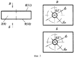
К причинам, препятствующим достижению указанного ниже технического результата при использовании известного способа, принятого за прототип, относится то, что в известном способе не оговариваются условия взаимного расположения друг относительно друга торцовых поверхностей 8, 9 ведущего ЗИ 3 (см. фиг. 1) (при вертикальном исполнении ведомого 6 и ведущего 5 валов в конструкции приводного механизма - это, например, соответственно верхняя и нижняя торцовые поверхности, а при горизонтальном - например, левая и правая) относительно торцовых поверхностей 10, 11 ведомого ЗИ 4, что весьма важно для случая, когда в состав передачи входят ЗИ, полученные ЭЭВ. При изготовлении входящих в состав зубчатой передачи (ЗП) ЗИ, а точнее их зубчатых венцов (ЗВ), ЭЭВ образуется конусность боковых (исполнительных) поверхностей зубьев, величина которой обусловлена величиной износа проволочного электрода-инструмента (ЭИ), условиями прохождения рабочей жидкости через межэлектродное пространство и положением заготовки ЗИ относительно направляющих проволочного ЭИ. Если не регламентировать условия взаимного расположения торцовых поверхностей ведомого 4 и ведущего 3 ЗИ, полученных ЭЭВ, друг относительно друга, то после сборки контакт между боковыми поверхностями зубьев в передаче может быть реализован по одному из 4-х возможных вариантов: I, II, III, IV (фиг.2). Контакт между боковыми поверхностями зубьев ведомого 4 и ведущего 3 ЗИ по вариантам I и IV при наличии конусности приведет к нарушению кинематических функций ЗП (повлияет на величину бокового зазора в передаче, форму и расположение контактной линий и пятна контакта, вызовет колебание межосевого расстояния), что в последующем предопределит неравномерный износ боковых поверхностей зубьев и приведет к снижению работоспособности передачи. Контакт между боковыми поверхностями зубьев ведомого 4 и ведущего 3 ЗИ по вариантам II и III исключает недостатки, присущее вариантам I и IV, но при этом нет 100% гарантии в том, что при сборке один из этих вариантов (II или III) будет реализован. For reasons that impede the achievement of the technical result indicated below when using the known method adopted as a prototype, the known method does not stipulate conditions for the relative positioning of
Сущность изобретения заключается в решении задачи исключения вероятности реализации вариантов (I, IV) нежелательного контакта зубьев, приводящих к нарушению кинематических функций ЗП и снижению ее работоспособности. The essence of the invention is to solve the problem of eliminating the likelihood of the implementation of options (I, IV) of unwanted contact of the teeth, leading to a violation of the kinematic functions of the RF and reduce its performance.
Технический результат - повышение точности и работоспособности ЗП между валами с параллельными осями, в состав которых входят ЗИ, полученные ЭЭВ. The technical result is to increase the accuracy and efficiency of the RF between the shafts with parallel axes, which include the ZI obtained EEE.
Указанный технический результат достигается тем, что в известном способе сопряжения прямозубых ЗИ в передаче между валами с параллельными осями для передачи вращательного движения от ведущего вала 5 к ведомому валу 6 (фиг.1) обеспечивается совпадение осей симметрии 1 и 2 соответственно ведущего 3 и ведомого 4 ЗИ, проходящих перпендикулярно осям вращения ведущего 5 и ведомого 6 валов, регламентируется величина межосевого расстояния W, исключается проворот ведущего 3 и ведомого 4 ЗИ относительно оси вращения соответственно ведущего 5 и ведомого 6 валов по средствам шпоночного соединения 7. The specified technical result is achieved by the fact that in the known method of coupling spur gears in the transmission between shafts with parallel axes for transmitting rotational motion from the
Особенность заявляемого способа заключается в том, что с целью повышения точности и работоспособности ЗП между валами с параллельными осями, в состав которых входят ЗИ, полученные ЭЭВ, ЗИ ориентируются дополнительно таким образом, чтобы при сборке для компенсации конусности верхняя (левая) торцовая поверхность 8III ведущего ЗИ 3 (см. фиг.2) находилась в одной плоскости "П-П" с нижней (правой) торцовой поверхностью 10III ведомого ЗИ 4 или нижняя (правая) торцовая поверхность 9II ведущего ЗИ 3 находилась в одной плоскости "П-П" с верхней (левой) торцовой поверхностью 11II ведомого ЗИ 4, что достигается нанесением надписей на торцовые поверхности заготовок ЗИ в зоне, ограниченной окружностью посадочного отверстия диаметром dпо ЗИ и окружность впадин зубьев диаметром df (например, верхняя (левая) - "В.Л", нижняя (правая) - "Н. П") одним из электроконтактных способов (электроконтактным гравированием) до выполнения операции ЭЭВ зубьев 3В (фиг.3).A feature of the proposed method lies in the fact that in order to improve the accuracy and performance of the RFP between the shafts with parallel axes, which include ZI, obtained EEE, ZI are oriented in such a way that when assembling to compensate for the taper, the upper (left)
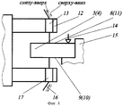
Кроме того, особенность способа заключается в том, что на операциях ЭЭВ зубьев 3В проволочным ЭИ 16 (фиг.4) заготовки 3 (4) соответственно ведущего и ведомого ЗИ, с нанесенными на их торцовые поверхности 8(11) и 9 (10) электроконтактным гравированием надписями соответственно "В.Л" и "Н.П", устанавливают на столе 15 электроэрозионного вырезного станка и закрепляют прихватом 14 таким образом, чтобы торцовые поверхности 8 (11) с надписью "В.Л" находились непосредственно под верхней направляющей 13 инструментальной скобы 12 станка или торцовые поверхности 9 (10) с надписью "Н.П" находились непосредственно над нижней направляющей 17. In addition, a feature of the method lies in the fact that in the EEE operations of the teeth 3B by wire EI 16 (Fig. 4), workpieces 3 (4) of the leading and driven ZI, respectively, are applied to their end surfaces 8 (11) and 9 (10) by engraving with the inscriptions “V.L.” and “N.P., respectively, they are mounted on the table 15 of the EDM cutter and secured with a
Кроме этого, особенность способа заключается в том, что ЭЭВ зубьев 3В каждого из ЗИ 3 (4) соответственно ведущего и ведомого, входящих в состав ЗП между валами с параллельными осями механизма привода должно осуществляться при прочих равных условиях (режимах обработки). In addition, a feature of the method lies in the fact that the EEE of the teeth 3B of each of the ZI 3 (4), respectively, of the leading and the follower, which are part of the RF between the shafts with parallel axes of the drive mechanism, must be carried out, all other conditions being equal (processing modes).
По имеющимся у авторов сведениям совокупность существенных признаков, характеризующих сущность заявляемого изобретения не известна из уровня техники, что позволяет сделать вывод о соответствии изобретения критерию "новизна". According to the information available to the authors, the set of essential features characterizing the essence of the claimed invention is not known from the prior art, which allows us to conclude that the invention meets the criterion of "novelty."
По мнению авторов, сущность заявляемого изобретения не следует для специалиста явным образом из известного уровня техники, так как из него не выявляется вышеуказанное влияние на получаемый технический результат - новое свойство объекта - совокупность признаков, которые отличают от прототипа заявляемое изобретение, что позволяет сделать вывод о его соответствии критерию "изобретательский уровень". According to the authors, the essence of the claimed invention does not follow explicitly from the prior art for a specialist, since the above effect on the obtained technical result is not revealed from it - a new property of the object - a set of features that distinguish the claimed invention from the prototype, which allows us to conclude its compliance with the criterion of "inventive step".
На чертежах представлено:
- на фиг. 1 показана схема сопряжения двух прямозубых ЗИ (ведущего 3 и ведомого 4), входящих в состав ЗП между валами с параллельными осями (ведущим 5 и ведомым 6);
- на фиг. 2 изображены варианты (I-IV) контакта между боковыми поверхностями зубьев ЗИ (ведущего 3 и ведомого 4), полученных ЭЭВ и входящих в состав ЗП между валами с параллельными осями (ведущим 5 и ведомым 6), в зависимости от условий взаимного расположения торцовых поверхностей ведущего и ведомого ЗИ и способа перемотки проволочного ЭИ при ЭЭВ (снизу-вверх или сверху-вниз);
- на фиг. 3 изображен эскиз заготовки 3 (4) соответственно ведущего и ведомого ЗИ, входящих в состав ЗП приводного механизма, обработанных на операциях, предшествующих операции ЭЭВ зубьев. Указаны места нанесения (зона, ограниченная окружностями диаметров dпо и df соответственно посадочного отверстия и впадин зубьев ЗИ) и сами надписи (В.Л и Н.П), обозначающее соответственно верхнюю (левую) и нижнюю (правую) торцовые поверхности заготовки;
- на фиг.4 изображена принципиальная схема расположения заготовок 3 (4) ЗИ на операции ЭЭВ проволочным ЭИ 16 относительно верхней 13 и нижней 17 направляющих инструментальной скобы 12 электроэрозионного вырезного станка.The drawings show:
- in FIG. 1 shows a pairing diagram of two spur gears (
- in FIG. Figure 2 shows the options (I-IV) of the contact between the side surfaces of the teeth of the ZI (
- in FIG. 3 shows a sketch of the workpiece 3 (4), respectively, of the leading and driven ZI, which are part of the RF of the drive mechanism, processed in operations preceding the operation of the EEE teeth. The places of application are indicated (the area bounded by circles of diameters d along and d f respectively of the landing hole and hollows of the ZI teeth) and the inscriptions themselves (V.L and N.P.), indicating the upper (left) and lower (right) end surfaces of the workpiece, respectively;
- figure 4 shows a schematic diagram of the location of the workpieces 3 (4) ZI on the EEE operation by
Предлагаемый способ сопряжения прямозубых ЗИ в передачах между валами с параллельными осями реализуется следующим образом:
- в соответствии с типовой технологией осуществляют обработку прямозубых ЗИ, входящих в состав ЗП между валами с параллельными осями приводного механизма. Венец каждого из ЗИ формируется ЭЭВ при прочих равных режимах обработки ЭИ на электроэрозионном вырезном станке с ЧПУ от управляющей программы, обеспечивающей необходимую траекторию перемещения ЭИ на формообразование ЗВ заданной геометрии. Перед выполнением операции ЭЭВ зубьев ЗВ, заготовку ЗИ 3 или 4 (фиг. 4) с нанесенными на их торцовые поверхности электроконтактным гравированием надписями ("В.Л" и "Н.П") устанавливают на столе 15 электроэрозионного вырезного станка таким образом, чтобы верхняя (левая) - "В.Л" торцовая поверхность заготовки 3 или 4 находилась непосредственно под верхней направляющей 13 инструментальной скобы 12 станка или наоборот нижняя (правая) - "Н.П" непосредственно над нижней направляющей 17;
- полученные ЭЭВ ЗИ (ведущее 3 и ведомое 4) (фиг.2), входящие в состав ЗП между валами с параллельными осями приводного механизма, перед установкой их на соответствующие валы (ведущий 5 и ведомый 6) ориентируют так, чтобы после установки (сборки) торцовая поверхность 8III ведущего ЗИ 3 с надписью на ней "В. Л" находилась в одной плоскости "П-П" с торцовой поверхностью 10III ведомого ЗИ 4 с надписью на ней "Н.П" или торцовая поверхность 9II ведущего ЗИ 3 с надписью на ней "Н.П" находилась в одной плоскости "П-П" с торцовой поверхностью 11II ведомого ЗИ 4 с надписей на ней "В.Л". Дальнейшими действиями при сборке обеспечивают совпадение осей симметрии 1 и 2 соответственно ведущего 3 и ведомого 4 ЗИ, как показано на фиг.1. Величина межосевого расстояния W регламентируется точностью межосевых расстояний между посадочными отверстиями под шейки валов в корпусе приводного механизма. Исключение проворота ведущего 3 и ведомого 4 ЗИ относительно оси вращения соответственно ведущего 5 и ведомого 6 валов, обеспечивается конструктивной проработкой шпоночного соединения 7 (фиг.1). В результате будет обеспечена передача крутящего момента с ведущего вала 5 на ведомый 6 (фиг.2), контакт между боковыми поверхностями зубьев ведущего 3 и ведомого 4 ЗИ в передаче будет гарантированно реализован по II или III вариантам, исключая I и IV.The proposed method of pairing spur gearboxes in gears between shafts with parallel axes is implemented as follows:
- in accordance with standard technology, the processing of spur gears included in the composition of the joint between shafts with parallel axes of the drive mechanism. The crown of each ZI is formed by EEE with all other conditions being equal to the processing of EI on an EDM cutting machine with CNC from a control program that provides the necessary trajectory of movement of EI to form the pollutant of a given geometry. Before performing the EEE operation of the teeth of the pollutants, the
- received EEE ZI (
Таким образом, изложенные сведения свидетельствуют о выполнении при использовании заявленного способа следующей совокупности условий:
- средство, воплощающее заявленный способ при его осуществлении, предназначено для использования в промышленности, а именно в машино-, приборостроении при производстве различного рода приводных механизмов передачи вращательных движений между валами с параллельными осями, в состав которых входят прямозубые ЗИ, полученные ЭЭВ;
- для заявленного способа в том виде, как он охарактеризован в независимом пункте изложенной формулы изобретения, подтверждена возможность его осуществления с помощью описанных в заявке или известных до даты приоритета средств и методов. Следовательно, заявленное изобретение соответствует условию "промышленная применимость".Thus, the above information indicates that when using the claimed method the following set of conditions:
- a tool embodying the claimed method in its implementation, is intended for use in industry, namely in machine-building, instrument-making in the manufacture of various kinds of drive mechanisms for transmitting rotational movements between shafts with parallel axes, which include spur gears obtained by EEE;
- for the claimed method in the form described in the independent clause of the claims, the possibility of its implementation using the means and methods described in the application or known prior to the priority date is confirmed. Therefore, the claimed invention meets the condition of "industrial applicability".
Claims (3)
Priority Applications (1)
| Application Number | Priority Date | Filing Date | Title |
|---|---|---|---|
| RU2001110989A RU2191663C1 (en) | 2001-04-20 | 2001-04-20 | Method of engagement of spur-gear toothed articles produced by electrical discharge cutting in gear trains between shafts with parallel axes |
Applications Claiming Priority (1)
| Application Number | Priority Date | Filing Date | Title |
|---|---|---|---|
| RU2001110989A RU2191663C1 (en) | 2001-04-20 | 2001-04-20 | Method of engagement of spur-gear toothed articles produced by electrical discharge cutting in gear trains between shafts with parallel axes |
Publications (1)
| Publication Number | Publication Date |
|---|---|
| RU2191663C1 true RU2191663C1 (en) | 2002-10-27 |
Family
ID=20248806
Family Applications (1)
| Application Number | Title | Priority Date | Filing Date |
|---|---|---|---|
| RU2001110989A RU2191663C1 (en) | 2001-04-20 | 2001-04-20 | Method of engagement of spur-gear toothed articles produced by electrical discharge cutting in gear trains between shafts with parallel axes |
Country Status (1)
| Country | Link |
|---|---|
| RU (1) | RU2191663C1 (en) |
Citations (3)
| Publication number | Priority date | Publication date | Assignee | Title |
|---|---|---|---|---|
| RU2071884C1 (en) * | 1991-05-31 | 1997-01-20 | Шармий Текнолоджи С.А. | Machine for electroerosion treatment of stationary part by wire tool-electrode |
| RU2093298C1 (en) * | 1995-04-10 | 1997-10-20 | Ульяновский государственный технический университет | Method for manufacturing press moulds for production of investment patterns of noncircular gear wheels |
| RU2147497C1 (en) * | 1998-12-15 | 2000-04-20 | Ульяновский государственный технический университет | Method of electroerosing machining of dies for manufacture of spur gears |
-
2001
- 2001-04-20 RU RU2001110989A patent/RU2191663C1/en active
Patent Citations (3)
| Publication number | Priority date | Publication date | Assignee | Title |
|---|---|---|---|---|
| RU2071884C1 (en) * | 1991-05-31 | 1997-01-20 | Шармий Текнолоджи С.А. | Machine for electroerosion treatment of stationary part by wire tool-electrode |
| RU2093298C1 (en) * | 1995-04-10 | 1997-10-20 | Ульяновский государственный технический университет | Method for manufacturing press moulds for production of investment patterns of noncircular gear wheels |
| RU2147497C1 (en) * | 1998-12-15 | 2000-04-20 | Ульяновский государственный технический университет | Method of electroerosing machining of dies for manufacture of spur gears |
Non-Patent Citations (1)
| Title |
|---|
| КОЗЛОВ М.П. Зубчатые передачи точного приборостроения. - М.: Машиностроение, 1969, с. 158 и 159. * |
Similar Documents
| Publication | Publication Date | Title |
|---|---|---|
| US8523634B2 (en) | Method for the grinding of a profile of a workpiece | |
| CN104816045B (en) | Non-circular gear Gear Shaping method | |
| CN101518843A (en) | Method and apparatus for working a screw rotor, end mill for working , and method of manufacturing a screw compressor | |
| CN107530803A (en) | The tooth-making method of tooth finishing and combinations thereof cutter | |
| JP2013212579A (en) | Method for producing conical wheel or hypoid wheel using plunging process | |
| CN207771067U (en) | Planer type numerical control robotic cutting machine | |
| RU2191663C1 (en) | Method of engagement of spur-gear toothed articles produced by electrical discharge cutting in gear trains between shafts with parallel axes | |
| US9789553B2 (en) | Tool, method and machine for producing a tooth profile on a workpiece by skiving | |
| CN102059418B (en) | A cylindrical gear full-closed-loop numerical control machining system and machining method | |
| CN106002118A (en) | Intermediate gear machining process | |
| CN208357946U (en) | It is a kind of for processing the special horizontal milling machine of line gear | |
| CN204221132U (en) | A kind of chamfering machine radial feed device | |
| GB1593225A (en) | Method of and means for grinding pairs of gear wheels as spiral or curved toothed bevel gear wheels | |
| CN107971581B (en) | Gear milling machine with gear indexing mechanism | |
| CN102233462A (en) | Improved transmission system of gear milling machine based on numerical control (NC) technology | |
| JPH11118023A (en) | Gears and gear pumps | |
| CN210502044U (en) | Three-dimensional carving machine | |
| JP3935914B2 (en) | Gear forming cutter | |
| KR20220083116A (en) | Processing control apparatus of machine tool and method thereof | |
| US5312210A (en) | Apparatus for machining teeth | |
| SU1729706A1 (en) | Method for production of herringbone gear wheel | |
| SU745612A1 (en) | Method of working toothed wheels | |
| SU1720815A1 (en) | Method for machining straight cut bevel gears by means of nc machine tools | |
| KR102648378B1 (en) | Worm screw processing device that maintains the directionality of the processing tool | |
| CN105234498A (en) | Equal-arc-length slotting method of non-circular gears |