RU2189318C2 - Drum for assembly of tyres with devices for turn-up of tyre band edges - Google Patents
Drum for assembly of tyres with devices for turn-up of tyre band edges Download PDFInfo
- Publication number
- RU2189318C2 RU2189318C2 RU99124577/12A RU99124577A RU2189318C2 RU 2189318 C2 RU2189318 C2 RU 2189318C2 RU 99124577/12 A RU99124577/12 A RU 99124577/12A RU 99124577 A RU99124577 A RU 99124577A RU 2189318 C2 RU2189318 C2 RU 2189318C2
- Authority
- RU
- Russia
- Prior art keywords
- levers
- tire
- ring
- segments
- drum
- Prior art date
Links
Images
Classifications
-
- B—PERFORMING OPERATIONS; TRANSPORTING
- B29—WORKING OF PLASTICS; WORKING OF SUBSTANCES IN A PLASTIC STATE IN GENERAL
- B29D—PRODUCING PARTICULAR ARTICLES FROM PLASTICS OR FROM SUBSTANCES IN A PLASTIC STATE
- B29D30/00—Producing pneumatic or solid tyres or parts thereof
- B29D30/06—Pneumatic tyres or parts thereof (e.g. produced by casting, moulding, compression moulding, injection moulding, centrifugal casting)
- B29D30/08—Building tyres
- B29D30/20—Building tyres by the flat-tyre method, i.e. building on cylindrical drums
- B29D30/32—Fitting the bead-rings or bead-cores; Folding the textile layers around the rings or cores
-
- B—PERFORMING OPERATIONS; TRANSPORTING
- B29—WORKING OF PLASTICS; WORKING OF SUBSTANCES IN A PLASTIC STATE IN GENERAL
- B29D—PRODUCING PARTICULAR ARTICLES FROM PLASTICS OR FROM SUBSTANCES IN A PLASTIC STATE
- B29D30/00—Producing pneumatic or solid tyres or parts thereof
- B29D30/06—Pneumatic tyres or parts thereof (e.g. produced by casting, moulding, compression moulding, injection moulding, centrifugal casting)
- B29D30/08—Building tyres
- B29D30/20—Building tyres by the flat-tyre method, i.e. building on cylindrical drums
- B29D30/24—Drums
- B29D30/244—Drums for manufacturing substantially cylindrical tyre components with cores or beads, e.g. carcasses
- B29D30/245—Drums for the single stage building process, i.e. the building-up of the cylindrical carcass and the toroidal expansion of it are realised on the same drum
-
- B—PERFORMING OPERATIONS; TRANSPORTING
- B29—WORKING OF PLASTICS; WORKING OF SUBSTANCES IN A PLASTIC STATE IN GENERAL
- B29D—PRODUCING PARTICULAR ARTICLES FROM PLASTICS OR FROM SUBSTANCES IN A PLASTIC STATE
- B29D30/00—Producing pneumatic or solid tyres or parts thereof
- B29D30/06—Pneumatic tyres or parts thereof (e.g. produced by casting, moulding, compression moulding, injection moulding, centrifugal casting)
- B29D30/08—Building tyres
- B29D30/20—Building tyres by the flat-tyre method, i.e. building on cylindrical drums
- B29D30/32—Fitting the bead-rings or bead-cores; Folding the textile layers around the rings or cores
- B29D2030/3214—Locking the beads on the drum; details of the drum in the bead locking areas, e.g. drum shoulders
-
- B—PERFORMING OPERATIONS; TRANSPORTING
- B29—WORKING OF PLASTICS; WORKING OF SUBSTANCES IN A PLASTIC STATE IN GENERAL
- B29D—PRODUCING PARTICULAR ARTICLES FROM PLASTICS OR FROM SUBSTANCES IN A PLASTIC STATE
- B29D30/00—Producing pneumatic or solid tyres or parts thereof
- B29D30/06—Pneumatic tyres or parts thereof (e.g. produced by casting, moulding, compression moulding, injection moulding, centrifugal casting)
- B29D30/08—Building tyres
- B29D30/20—Building tyres by the flat-tyre method, i.e. building on cylindrical drums
- B29D30/32—Fitting the bead-rings or bead-cores; Folding the textile layers around the rings or cores
- B29D2030/3221—Folding over means, e.g. bladders or rigid arms
- B29D2030/3264—Folding over means, e.g. bladders or rigid arms using radially expandable, contractible mechanical means, e.g. circumferentially spaced arms, spring rollers, cages
Abstract
Description
Изобретение относится к барабану для сборки шин с устройством для заворота кромок браслета шины вверх для сборки невулканизированной шины с элементами из резины или имеющей усилительный корд и два сердечника борта с высокими наполнительными шнурами, причем вышеуказанный барабан для сборки шин имеет центральную ось, два кольцеобразных сегмента, размещенных вокруг этой оси и расположенных на расстоянии друг от друга для поддержки бортового дорна, сегменты барабана, расположенные вокруг оси и на внешней стороне каждого из кольцеобразных сегментов, причем эти сегменты барабана образуют цилиндрическую поверхность для поддержки элементов шины, средства для радиального расширения той части элементов шины, которая расположена между кольцеобразными сегментами, при этом барабан для сборки шин имеет на обеих сторонах за пределами кольцеобразных сегментов первый комплект аксиально выступающих шарнирных рычагов, причем каждый рычаг имеет конец, направленный на кольцеобразный сегмент, причем вышеуказанный конец имеет ролик, средство для аксиального и радиального перемещения каждого первого комплекта рычагов из первой позиции, в которой ролики первого комплекта рычагов образуют фактически замкнутое кольцо, во вторую позицию, чтобы прижимать расширенную часть элементов шины, которая расположена между кольцеобразными сегментами, к той части элементов шины, которая расположена за пределами кольцеобразных сегментов. The invention relates to a drum for assembling tires with a device for turning the edges of the bracelet of the tire up for assembling an unvulcanized tire with rubber elements or having an reinforcing cord and two bead cores with high filling cords, the aforementioned drum for assembling tires has a central axis, two ring-shaped segments, located around this axis and located at a distance from each other to support the side mandrel, drum segments located around the axis and on the outside of each of the annular segments, and these drum segments form a cylindrical surface for supporting the tire elements, means for radially expanding that part of the tire elements that is located between the ring-shaped segments, while the tire assembly drum has on the both sides outside the ring-shaped segments a first set of axially protruding articulated arms, moreover, each lever has an end directed to the annular segment, the above end having a roller, means for axial and radial movement each first set of arms from a first position in which the first set of arms form a virtually rollers closed ring to a second position to press the expanded part of the tire components which is situated between the ring segments to the part of the tire components which is situated outside the ring segments.
Такой барабан для сборки шин с устройством для заворота кромок браслета шины вверх уже известен из описания к патенту Великобритании 1532960. Этот известный барабан для сборки шин включает два комплекта рычагов, один комплект на одной стороне кольцеобразных сегментов, а другой комплект на другой стороне за пределами кольцеобразных сегментов. При перемещении рычагов из первой позиции во вторую позицию ролики располагаются на большем расстоянии от оси, в результате чего эти ролики находятся на расстоянии друг от друга и, таким образом, более не образуют фактически замкнутое кольцо. Так как вторая позиция несколько дальше от центральной оси барабана для сборки шин, чем первая позиция, то часть элементов шины, расположенная за пределами кольцеобразных сегментов, не бывает полностью прижата по всей высоте к части элементов шины, расположенной между кольцеобразными сегментами, и, более того, края рычагов располагаются на расстоянии друг от друга таким образам, что получается неполное прижатие по окружности с помощью роликов. Чтобы предотвратить неполное крепление элементов шины, что может нанести ущерб качеству изготавливаемой шины, вокруг рычагов располагается рукав из резины. Такой рукав из резины, тем не менее, имеет ограниченный срок эксплуатации. Such a tire assembly drum with a device for winding up the edges of a tire bracelet up is already known from the British Patent Specification 1,532,960. This known tire assembly drum includes two sets of levers, one set on one side of the ring segments and the other set on the other side outside the ring segments. When the levers are moved from the first position to the second position, the rollers are located at a greater distance from the axis, as a result of which these rollers are spaced from each other and thus no longer form a virtually closed ring. Since the second position is slightly farther from the central axis of the tire assembly drum than the first position, the part of the tire elements located outside the ring-shaped segments is not fully pressed along the entire height to the part of the tire elements located between the ring-shaped segments, and, moreover , the edges of the levers are located at a distance from each other in such a way that incomplete compression around the circumference with the help of rollers is obtained. To prevent incomplete fastening of tire elements, which can damage the quality of the manufactured tire, a rubber sleeve is located around the levers. Such a rubber sleeve, however, has a limited life.
Цель настоящего изобретения состоит в создании барабана для сборки шин с устройством для заворота кромок браслета шины вверх для сборки невулканизированной шины с элементами из резины или имеющей усилительные корды и два сердечника борта с высокими наполнительными шнурами, в котором без использования резинового рукава части элементов шины могут быть прижаты друг к другу по замкнутой окружности и полностью по высоте, что повышает качество готовой шины. An object of the present invention is to provide a tire assembly drum with a device for turning the edges of a tire bracelet up to assemble an unvulcanized tire with rubber elements or having reinforcing cords and two bead cores with high filling cords, in which parts of the tire elements can be without using a rubber sleeve pressed against each other in a closed circle and completely in height, which improves the quality of the finished tire.
С этой целью барабан для сборки шин с устройством для заворота кромок браслета шины вверх в соответствии с настоящим изобретением отличается тем, что каждый первый комплект рычагов содержит второй комплект аксиально выступающих шарнирных рычагов, причем каждый рычаг имеет конец, направленный на кольцеобразный сегмент, при этом вышеуказанный конец имеет ролик, при этом каждый ролик рычага из второго комплекта расположен между двумя соседними рычагами вышеуказанного первого комплекта и расположен на той стороне роликов рычагов вышеуказанного первого комплекта, которая повернута от кольцеобразных сегментов, и эти средства предусмотрены для аксиального и радиального перемещения каждого второго комплекта рычагов из первой позиции, в которой ролики из второго комплекта рычагов образуют фактически замкнутое кольцо второй позиции, чтобы прижимать расширенную часть элементов шины, которая расположена между кольцеобразными сегментами, к той части элементов шины, которая расположена за пределами кольцеобразных сегментов. Так как ролики рычагов второго комплекта расположены между рычагами первого комплекта, то части элементов шины бывают прижаты друг к другу по почти замкнутой окружности во второй позиции роликов обоих комплектов, в результате чего, по меньшей мере, достигается почти полное крепление элементов шины. To this end, a tire assembly drum with a device for turning the edges of a tire bracelet up in accordance with the present invention is characterized in that each first set of levers comprises a second set of axially protruding articulated levers, each lever having an end directed towards an annular segment, wherein the end has a roller, wherein each lever roller from the second set is located between two adjacent levers of the above first set and is located on that side of the levers rollers of the above of the first set, which is turned away from the ring-shaped segments, and these means are provided for axial and radial movement of each second set of levers from the first position, in which the rollers from the second set of levers form a virtually closed ring of the second position to press the expanded part of the tire elements, which is located between the ring-shaped segments, to that part of the tire elements, which is located outside the ring-shaped segments. Since the rollers of the levers of the second set are located between the levers of the first set, parts of the tire elements are pressed against each other in an almost closed circle in the second position of the rollers of both sets, as a result of which at least almost complete fastening of the tire elements is achieved.
Предпочтительный вариант осуществления барабана для сборки шин с устройством для заворота кромок браслета шины вверх в соответствии с настоящим изобретением отличается тем, что средство для аксиального и радиального перемещения каждого первого комплекта рычагов и средство для аксиального и радиального перемещения каждого второго комплекта рычагов образованы одним и тем же средством. Таким образом, устройство для заворота кромок браслета шины вверх барабана для сборки шин может быть выполнено не только с более компактной конструкцией, но также с синхронизацией перемещения комплекта рычагов из первой позиции во вторую позицию простым способом. A preferred embodiment of a tire assembly drum with a device for turning the edges of a tire bracelet up in accordance with the present invention is characterized in that the means for axially and radially moving each first set of levers and the means for axially and radially moving each second set of levers are formed by the same means. Thus, the device for turning the edges of the tire bracelet upwards of the tire assembly drum can be made not only with a more compact design, but also with synchronizing the movement of the set of levers from the first position to the second position in a simple way.
Следующий предпочтительный вариант осуществления барабана для сборки шин с устройством для заворота кромок браслета шины вверх в соответствии с настоящим изобретением отличается тем, что предусмотрены средства для поддерживания в боковом направлении двух сердечников борта с высокими наполнительными шнурами, в котором эти средства расположены между кольцеобразными сегментами и предпочтительно имеют возможность поворота из нерабочей позиции в рабочую позицию. Таким образом, предотвращается такая ситуация, при которой рычаги при переходе из первой позиции во вторую выталкивают сердечники борта с высокими наполнительными шнурами с их мест. Когда эти средства имеют возможность поворота из нерабочей позиции в рабочую позицию, исключается отрицательное влияние на нормальную работу барабана для сборки шин. A further preferred embodiment of the tire assembly drum with the device for turning the edges of the tire bracelet up in accordance with the present invention is characterized in that means are provided for laterally supporting two bead cores with high filler cords in which these means are located between the annular segments and preferably have the ability to rotate from a non-working position to a working position. Thus, a situation is prevented in which the levers during the transition from the first position to the second push the bead cores with high filling cords from their places. When these tools have the ability to rotate from a non-working position to a working position, the negative impact on the normal operation of the tire assembly drum is eliminated.
В качестве примера некоторые варианты выполнения барабана для сборки шин с устройством для заворота кромок браслета шины вверх в соответствии с настоящим изобретением будут рассмотрены со ссылкой на чертежи , в которых:
на фиг.1 схематично показан продольный разрез барабана для сборки шин с устройством для заворота кромок браслета шины вверх в соответствии с настоящим изобретением, причем рычаги находятся в первой позиции;
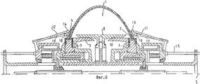
на фиг.2 схематично показан продольный разрез барабана для сборки шин с устройством для заворота кромок браслета шины вверх в соответствии с настоящим изобретением, причем рычаги находятся во второй позиции, а часть элементов шины, которая расположена между кольцеобразными сегментами, расширена;
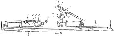
на фиг. 3 схематично показан продольный разрез альтернативного варианта выполнения барабана для сборки шин с устройством для заворота кромок браслета шины вверх в соответствии с настоящим изобретением, где в левой половине чертежа рычаги показаны в первой позиции, а в правой половине чертежа рычаги показаны во второй позиции;
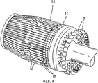
на фиг. 4 схематично показано пространственное изображение одного комплекта рычагов в первой позиции и некоторые части устройства для заворота кромок браслета шины вверх барабана для сборки шин в соответствии с настоящим изобретением, чтобы представить на примере трехмерную конфигурацию.As an example, some embodiments of a drum for assembling tires with a device for turning the edges of a tire bracelet up in accordance with the present invention will be discussed with reference to the drawings, in which:
figure 1 schematically shows a longitudinal section of a drum for assembling tires with a device for turning the edges of the bracelet of the tire up in accordance with the present invention, and the levers are in the first position;
figure 2 schematically shows a longitudinal section of a drum for assembling tires with a device for turning the edges of the bracelet of the tire up in accordance with the present invention, the levers being in the second position, and the part of the tire elements, which is located between the ring-shaped segments, expanded;
in FIG. 3 schematically shows a longitudinal section through an alternative embodiment of a tire assembly drum with a device for turning the edges of a tire bracelet up in accordance with the present invention, where the levers are shown in the first position in the left half of the drawing and the levers are shown in the second half in the right half of the drawing;
in FIG. 4 schematically shows a spatial view of one set of levers in a first position and some parts of a device for turning the edges of a tire bracelet upwards of a tire assembly drum in accordance with the present invention, in order to illustrate a three-dimensional configuration.
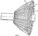
На фиг. 5 схематично показано пространственное изображение одного комплекта рычагов во второй позиции и некоторые части устройства для заворота кромок браслета шины вверх в соответствии с настоящим изобретением, чтобы представить на примере трехмерную конфигурацию. In FIG. 5 schematically shows a spatial view of one set of levers in a second position and some parts of a device for turning the edges of a tire bracelet up in accordance with the present invention, to present a three-dimensional configuration as an example.
На фиг.1 схематично показан продольный разрез барабана для сборки шин с устройством для заворота кромок браслета шины вверх в соответствии с настоящим изобретением для сборки невулканизированной шины. Такая невулканизированная шина содержит элементы из резины или имеет усилительные корды (из которых на фиг.1 показаны оба, 1 и 2) и два сердечника 3 и 4 борта с высокими наполнительными шнурами. Число и тип элементов шины зависят от готовой шины, которая должна быть изготовлена, а возможные узлы и конструкция достаточно известны специалисту, так что более подробное обсуждение этого будет пропущено. Figure 1 schematically shows a longitudinal section of a tire assembly drum with a device for turning the edges of a tire bracelet up in accordance with the present invention for assembling an unvulcanized tire. Such an unvulcanized tire contains rubber elements or has reinforcing cords (of which both 1 and 2 are shown in FIG. 1) and two
Барабан для сборки шин имеет центральную ось 5. Вокруг оси 5 и на расстоянии друг от друга расположены два кольцеобразных сегмента 6 и 7, каждый для поддержки соответствующего сердечника 3 и соответственно 4 борта. Вокруг оси 5 и на внешней стороне каждого кольцеобразного сегмента 6, 7 расположены сегменты барабана, образованные рычагами 11 и 12, причем эти сегменты барабана образуют цилиндрическую поверхность для поддержки элементов шины 1, 2. Кольцеобразные сегменты 6, 7 могут также служить для поддержки определенных элементов шины, таких как относительно узкие усилительные полосы. The tire assembly drum has a
На фиг. 1 показан пример барабана для сборки шин, в этом случае также с сегментами барабана 8, 9 и 10 между кольцеобразными сегментами. Как уже известно, имеются средства (не показанные на чертеже) для радиального перемещения, по меньшей мере, части сегментов барабана (особенно сегмент 8 барабана), и средства (не показаны на чертеже) для радиального расширения той части элементов шины, которая расположена между кольцеобразными сегментами 6, 7. In FIG. 1 shows an example of a drum for assembling tires, in this case also with
Барабан для сборки шин на обеих сторонах с внешней стороны кольцеобразных сегментов 6, 7 имеет первый комплект аксиально выступающих шарнирных рычагов 11 и соответственно 12. Каждый рычаг 11, 12 имеет край, направленный к кольцеобразному сегменту 6 и соответственно 7, причем вышеуказанный край имеет ролик 13 и соответственно 14. Как уже известно, имеются средства (15, фиг. 2) для аксиального и радиального перемещения каждого первого комплекта рычагов 11, 12 из первой позиции (представленной на фиг.1), на которой ролики 13, 14 из первого комплекта рычагов 11, 32 образуют фактически замкнутое кольцо во второй позиции (показана на фиг.2) для прижимания расширенной части элементов шины, которая расположена между кольцеобразными сегментами 6, 7, к части элементов шины, которая расположена на внешней стороне кольцеобразных сегментов 6, 7. The tire assembly drum on both sides of the outer side of the ring-
Далее будет рассмотрен признак барабана для сборки шин, основной для настоящего изобретения, который состоит в наличии устройства для заворота кромок браслета шины вверх, а другие элементы барабана для сборки шин, которые хорошо известны специалисту, детально рассматриваться не будут. Next, a feature of a tire assembly drum that is fundamental to the present invention will be considered, which consists in having a device for turning the edges of a tire bracelet upward, and other elements of a tire assembly drum that are well known to one skilled in the art will not be considered in detail.
В соответствии с настоящим изобретением предлагается барабан для сборки шин с устройством для заворота кромок браслета шины вверх, в котором каждый первый комплект рычагов (11 или 12) содержит второй комплект аксиально выступающих шарнирных рычагов (17 и соответственно 19, см. фиг.2 и 4). Каждый рычаг 17, 19 каждого второго комплекта имеет край, направленный к кольцеобразному сегменту 6 и соответственно 7, причем вышеуказанный край имеет ролик 16 и соответственно 18. Каждый ролик 16, 18 рычага 17, 19 каждого второго комплекта расположен между двумя соседними рычагами 11, 12 вышеуказанного первого комплекта, каждый ролик 16, 18 второго комплекта расположен на той стороне роликов 13, 14 рычагов 11, 12 вышеуказанного первого комплекта, которая повернута от кольцеобразных сегментов 6, 7. In accordance with the present invention, there is provided a drum assembly for assembling tires with a device for turning the edges of a tire bracelet upwards, in which each first set of levers (11 or 12) comprises a second set of axially protruding articulated levers (17 and 19, respectively, see FIGS. 2 and 4 ) Each
Далее имеются средства, предпочтительно средства 15, для аксиального и радиального перемещения каждого второго комплекта рычагов из первой позиции, в которой ролики 16, 18 второго комплекта рычагов 17, 19 образуют фактически замкнутое кольцо, во вторую позицию, для прижатия расширенной части элементов шины, которая расположена между кольцеобразными сегментами 6, 7, к той части элементов шины, которая расположена за пределами кольцеобразных сегментов 6, 7. Средства для аксиального и радиального перемещения комплекта рычагов предпочтительно включают гибкие шнуры, расположенные вокруг комплекта рычагов, чтобы прижимать рычаги для их перевода из второй позиции обратно в первую позицию. Further, there are means, preferably means 15, for axial and radial movement of each second set of levers from the first position, in which the
Так как ролики 16, 18 рычагов 17, 19 второго комплекта расположены между роликами 13, 14 рычагов 11, 12 первого комплекта, во второй позиции роликов на обоих комплектах почти по всей окружности части элементов шины прижаты друг к другу (как показано на фиг.2 и 5), в результате чего достигается почти полное крепление элементов шины. Since the
На фиг.3 схематично показано продольное сечение (показана только верхняя половина, нижняя половина симметрична) альтернативного известного варианта выполнения барабана для сборки шин с устройством для затвора кромок браслета шины вверх в соответствии с настоящим изобретением для сборки невулканизированной шины. Такая невулканизированная шина состоит из элементов шины из резины или имеет усилительные корды, два из которых, 1' и 2', показаны в правой части фиг.3, и два сердечника борта с высокими наполнительными шнурами, из которых показан только один, 4'. Барабан для сборки шин имеет центральную ось 5'. Вокруг оси 5' и на расстоянии друг от друга расположены два кольцеобразных сегмента 6' и 7', каждый для поддержки соответствующего сердечника борта. Кольцеобразные сегменты 6' и 7' служат для поддержки элементов шины 1' и 2'. Первоначально два комплекта рычагов, 11', 17' и 12', 19', когда они находятся в первой позиции, используются для поддерживания той части элементов шины, которая находится за пределами кольцеобразных сегментов. Каждый рычаг 11', 12' (17', 19') имеет край, направленный к кольцеобразному сегменту 6' и соответственно, 7', причем вышеуказанный край имеет ролик 13' соответственно 14' (16', 18'). Каждый комплект рычагов может быть перемещен из первой позиции (показана в левой половине фиг.3), в которой ролики из комплекта рычагов образуют фактически замкнутое кольцо, во вторую позицию (показана в правой половине фиг.3), чтобы прижимать расширенную часть элементов шины, которая расположена между кольцеобразными сегментами 6', 7', к той части элементов шины, которая находится за пределами кольцеобразных сегментов 6', 7'. Figure 3 schematically shows a longitudinal section (only the upper half is shown, the lower half is symmetrical) of an alternative known embodiment of a tire assembly drum with a device for closing the edges of a tire bracelet up in accordance with the present invention for assembling an unvulcanized tire. Such an unvulcanized tire consists of rubber tire elements or has reinforcing cords, two of which, 1 ′ and 2 ′, are shown on the right side of FIG. 3, and two bead cores with high filler cords, of which only one is shown, 4 ′. The tire assembly drum has a central axis of 5 '. Around the axis 5 'and at a distance from each other are two annular segments 6' and 7 ', each to support the corresponding core of the bead. The ring-
Каждый ролик 16', 18' рычага 17', 19' каждого второго комплекта расположен между двумя соседними рычагами 11', 12' вышеуказанного первого комплекта, каждый ролик 16', 18' второго комплекта расположен на той стороне роликов 13', 14' рычагов 11', 12' вышеуказанного первого комплекта, которая повернута от кольцеобразных сегментов 6', 7'. Each roller 16 ', 18' of the lever 17 ', 19' of each second set is located between two adjacent levers 11 ', 12' of the above first set, each roller 16 ', 18' of the second set is located on that side of the roller 13 ', 14' 11 ', 12' of the aforementioned first set, which is rotated from the annular segments 6 ', 7'.
Так как ролики 16', 18' рычагов 17', 19' второго комплекта расположены между роликами 13', 14' рычагов 11', 12' первого комплекта, во второй позиции роликов обоих комплектов, почти по всей окружности, части элементов шины прижаты один к другому, при этом также без использования рукава из резины достигается почти полное крепление элементов шины. Since the rollers 16 ', 18' of the levers 17 ', 19' of the second set are located between the rollers 13 ', 14' of the levers 11 ', 12' of the first set, in the second position of the rollers of both sets, almost along the entire circumference, one part of the tire elements is pressed one to the other, while also without using a rubber sleeve, almost complete fastening of the tire elements is achieved.
Кроме того, предлагаются средства 20, 21 (фиг.3) для поддерживания в боковом направлении вышеуказанных двух сердечников борта с высокими наполнительными шнурами, из которых один, 4', показан на фиг.3, на которой эти средства расположены между кольцеобразными сегментами 6', 7'. Вышеуказанные средства, находясь в рабочем положении, предотвращают нежелательные толчки сердечников борта с высокими наполнительными шнурами со стороны кольцеобразных сегментов рычагами при переходе из первой позиции во вторую. Предпочтительно средства 20, 21 для поддерживания в боковом направлении сердечников борта с высокими наполнительными шнурами имеют возможность поворота из нерабочей позиции в рабочую позицию. Таким образом, средства для поддерживания в боковом направлении сердечников борта с высокими наполнительными шнурами не мешают нормальной работе барабана для сборки шин и, более того, могут оказать помощь при поддерживании элементов шины в исходной позиции. In addition, means 20, 21 (FIG. 3) are proposed for laterally supporting the above two bead cores with high filler cords, of which one, 4 ′, is shown in FIG. 3, on which these means are located between the ring-
Claims (4)
Applications Claiming Priority (3)
| Application Number | Priority Date | Filing Date | Title |
|---|---|---|---|
| WOPCT/NL97/00290 | 1997-05-23 | ||
| NL9700290 | 1997-05-23 | ||
| WONL97/00290 | 1997-05-23 |
Publications (2)
| Publication Number | Publication Date |
|---|---|
| RU99124577A RU99124577A (en) | 2001-09-27 |
| RU2189318C2 true RU2189318C2 (en) | 2002-09-20 |
Family
ID=19866189
Family Applications (1)
| Application Number | Title | Priority Date | Filing Date |
|---|---|---|---|
| RU99124577/12A RU2189318C2 (en) | 1997-05-23 | 1997-07-22 | Drum for assembly of tyres with devices for turn-up of tyre band edges |
Country Status (10)
| Country | Link |
|---|---|
| US (2) | US6318434B1 (en) |
| EP (1) | EP1001876B1 (en) |
| JP (1) | JP4124829B2 (en) |
| KR (1) | KR100559114B1 (en) |
| CN (1) | CN1074982C (en) |
| AU (1) | AU3466497A (en) |
| DE (1) | DE69716774T2 (en) |
| RU (1) | RU2189318C2 (en) |
| SK (1) | SK286587B6 (en) |
| WO (1) | WO1998052740A1 (en) |
Cited By (1)
| Publication number | Priority date | Publication date | Assignee | Title |
|---|---|---|---|---|
| RU2649436C2 (en) * | 2013-06-28 | 2018-04-03 | Вми Холланд Б.В. | Tyre building drum with turn-up mechanism |
Families Citing this family (29)
| Publication number | Priority date | Publication date | Assignee | Title |
|---|---|---|---|---|
| CN1120774C (en) * | 1999-07-30 | 2003-09-10 | 倍耐力轮胎公司 | Tyre assembling apparatus |
| US7152649B2 (en) | 1999-07-30 | 2006-12-26 | Pirelli Pneumatici S.P.A. | Tire-assembling apparatus |
| WO2001068356A1 (en) * | 2000-03-17 | 2001-09-20 | Vmi Epe Holland B.V. | Tyre building drum provided with a turn-up device |
| JP2003025461A (en) * | 2001-05-11 | 2003-01-29 | Fuji Seiko Kk | Tire molding apparatus and pneumatic radial tire |
| JP4651885B2 (en) * | 2001-09-12 | 2011-03-16 | 株式会社ブリヂストン | Tire molding drum |
| KR100441959B1 (en) * | 2001-12-28 | 2004-07-27 | 한국타이어 주식회사 | Carcass Building Drum Apparatus for Green Tire |
| JP3616613B2 (en) * | 2002-06-03 | 2005-02-02 | 株式会社市丸技研 | Winding device for tire member end in tire molding machine |
| CN100572040C (en) * | 2002-08-05 | 2009-12-23 | 株式会社普利司通 | Tire assembly drum and tire moulding method |
| NL1021668C2 (en) * | 2002-10-16 | 2004-04-20 | Vmi Epe Holland | Tire drum with storage mechanism for building an unvulcanized tire. |
| US7387697B2 (en) | 2003-02-07 | 2008-06-17 | Bridgestone Corporation | Method and apparatus for turning up tire structure members |
| US20050028920A1 (en) * | 2003-08-04 | 2005-02-10 | Roedseth John Kolbjoern | High crown first stage tire building drum |
| NL1026334C2 (en) * | 2004-06-04 | 2005-12-06 | Vmi Epe Holland | Tire drum assembly with storage mechanism for building an unvulcanized tire. |
| US7288160B2 (en) * | 2004-12-23 | 2007-10-30 | The Goodyear Tire & Rubber Company | Method of making a tire using a high crown uni-stage tire building drum |
| US20070068631A1 (en) * | 2005-09-28 | 2007-03-29 | Brian Painter | Tyre building drum |
| EP2032350B1 (en) * | 2006-06-29 | 2011-03-09 | Pirelli Tyre S.p.A. | Process and apparatus for manufacturing a pneumatic tyre |
| ATE553914T1 (en) | 2007-10-25 | 2012-05-15 | Fuji Seiko Co Ltd | DEVICE FOR FOLDING A CARCASS PLY |
| JP5219272B2 (en) * | 2008-01-28 | 2013-06-26 | 株式会社ブリヂストン | Tire molding equipment |
| KR101440897B1 (en) * | 2008-07-23 | 2014-09-17 | 피렐리 타이어 소시에떼 퍼 아찌오니 | Process and apparatus for manufacturing tyres for vehicle wheels |
| NL2003874C2 (en) | 2009-11-26 | 2011-05-30 | Vmi Holland Bv | TIRE CONSTRUCTION DRUM WITH STORAGE MECHANISM. |
| MX2016015083A (en) * | 2014-05-27 | 2017-02-28 | Pirelli | Process and apparatus for building tyres. |
| JP6445917B2 (en) * | 2015-04-13 | 2018-12-26 | 住友ゴム工業株式会社 | Raw tire molding equipment |
| KR101708894B1 (en) * | 2015-08-03 | 2017-02-22 | 한국타이어 주식회사 | Bead lock apparatus of greentire shaping drum machine |
| NL2018011B1 (en) * | 2016-12-16 | 2018-06-26 | Vmi Holland Bv | Drum half, tire building machine and method for operating said tire building machine |
| US20200207045A1 (en) | 2017-06-16 | 2020-07-02 | Harburg-Freudenberger Maschinenbau Gmbh | Method and apparatus for manufacturing tires |
| WO2020013969A1 (en) * | 2018-07-10 | 2020-01-16 | Bridgestone Americas Tire Operations, Llc | Modular tire turn-up apparatus |
| CN109291481B (en) * | 2018-11-30 | 2020-10-20 | 萨驰华辰机械(苏州)有限公司 | Position detection system and position detection method for tire building drum |
| WO2021094033A1 (en) * | 2019-11-15 | 2021-05-20 | Compagnie Generale Des Etablissements Michelin | Turnup of rubber products without beadwires |
| KR102425923B1 (en) | 2020-10-08 | 2022-07-28 | 금호타이어 주식회사 | The molding device of green tire |
| KR102516983B1 (en) * | 2021-08-19 | 2023-04-04 | 금호타이어 주식회사 | Tire building machine |
Family Cites Families (15)
| Publication number | Priority date | Publication date | Assignee | Title |
|---|---|---|---|---|
| FR95396E (en) * | 1966-02-25 | 1970-09-11 | Nrm Corp | Radial carcass tire making drum. |
| FR2093180A5 (en) | 1970-06-04 | 1972-01-28 | Gazuit Georges | Radial tyre forming drum |
| US3692605A (en) | 1970-07-22 | 1972-09-19 | Nrm Corp | Ply turn-up and side wall applying bladder for tire building machine and method |
| JPS5022074A (en) * | 1973-06-27 | 1975-03-08 | ||
| US4131500A (en) | 1974-12-09 | 1978-12-26 | Avon Tyres Limited | Tire building drum |
| GB1532960A (en) * | 1974-12-09 | 1978-11-22 | Avon Tyres Ltd | Tyre building drum |
| SU717851A1 (en) | 1978-06-16 | 1991-01-30 | Предприятие П/Я А-3404 | Device for assembling pneumatic tyres |
| US4309235A (en) * | 1980-07-09 | 1982-01-05 | National-Standard Company | Retractable bead setter assembly and method of operation thereof |
| US4362592A (en) * | 1981-04-09 | 1982-12-07 | The B. F. Goodrich Company | Ply turn-up means in a tire building machine |
| GB2182894B (en) * | 1985-11-13 | 1989-10-04 | Bates W & A Ltd | Tyre building apparatus |
| JPH0429835A (en) | 1990-05-28 | 1992-01-31 | Bridgestone Corp | Drum for molding of tire |
| SK45993A3 (en) | 1993-05-12 | 1995-06-07 | Matador As | Winding and back folding part of drum tire building |
| FR2708515A1 (en) | 1993-08-04 | 1995-02-10 | Michelin & Cie | Method and machine for making tires. |
| DE9405694U1 (en) | 1994-04-06 | 1994-05-26 | Schaeffler Waelzlager Kg | Rocker arm for a valve train of an internal combustion engine |
| JPH09309159A (en) * | 1996-05-21 | 1997-12-02 | Mitsubishi Heavy Ind Ltd | Take-up device for tire member end for tire molding drum |
-
1997
- 1997-07-22 EP EP97930899A patent/EP1001876B1/en not_active Expired - Lifetime
- 1997-07-22 AU AU34664/97A patent/AU3466497A/en not_active Abandoned
- 1997-07-22 SK SK1552-99A patent/SK286587B6/en not_active IP Right Cessation
- 1997-07-22 RU RU99124577/12A patent/RU2189318C2/en active
- 1997-07-22 US US09/380,561 patent/US6318434B1/en not_active Expired - Lifetime
- 1997-07-22 CN CN97182206A patent/CN1074982C/en not_active Ceased
- 1997-07-22 KR KR1019997010809A patent/KR100559114B1/en not_active IP Right Cessation
- 1997-07-22 JP JP55025898A patent/JP4124829B2/en not_active Expired - Fee Related
- 1997-07-22 DE DE69716774T patent/DE69716774T2/en not_active Expired - Lifetime
- 1997-07-22 WO PCT/NL1997/000435 patent/WO1998052740A1/en active IP Right Grant
-
2001
- 2001-06-18 US US09/882,261 patent/US20020124968A1/en not_active Abandoned
Cited By (1)
| Publication number | Priority date | Publication date | Assignee | Title |
|---|---|---|---|---|
| RU2649436C2 (en) * | 2013-06-28 | 2018-04-03 | Вми Холланд Б.В. | Tyre building drum with turn-up mechanism |
Also Published As
| Publication number | Publication date |
|---|---|
| CN1074982C (en) | 2001-11-21 |
| JP2001525748A (en) | 2001-12-11 |
| EP1001876A1 (en) | 2000-05-24 |
| KR20010012844A (en) | 2001-02-26 |
| US20020124968A1 (en) | 2002-09-12 |
| KR100559114B1 (en) | 2006-03-13 |
| CN1254307A (en) | 2000-05-24 |
| SK286587B6 (en) | 2009-01-07 |
| AU3466497A (en) | 1998-12-11 |
| DE69716774T2 (en) | 2004-12-30 |
| WO1998052740A1 (en) | 1998-11-26 |
| EP1001876B1 (en) | 2002-10-30 |
| SK155299A3 (en) | 2000-05-16 |
| JP4124829B2 (en) | 2008-07-23 |
| US6318434B1 (en) | 2001-11-20 |
| DE69716774D1 (en) | 2002-12-05 |
Similar Documents
| Publication | Publication Date | Title |
|---|---|---|
| RU2189318C2 (en) | Drum for assembly of tyres with devices for turn-up of tyre band edges | |
| JP4943702B2 (en) | High crown single stage tire building drum | |
| EP3037249B1 (en) | Sleeveless tire building drum | |
| RU99124577A (en) | TIRE ASSEMBLY DRUM WITH DEVICE FOR TURNING UP THE TIRE BRACELET EDGE UP | |
| EP0238788A2 (en) | A carcass forming drum | |
| EP1645403B1 (en) | Method for molding bead portion of green tire and bead portion molding device | |
| US7288160B2 (en) | Method of making a tire using a high crown uni-stage tire building drum | |
| SK13382002A3 (en) | Tyre building drum provided with a turn-up device | |
| US4149927A (en) | Tire building apparatus with improved drum shoulder | |
| EP2698244B1 (en) | Sleeveless tire building drum with interchangeable width elements | |
| US5181982A (en) | Tire forming drum including stitching supports | |
| KR100982726B1 (en) | Tyre drum with turn-up mechanism for building an unvulcanized tyre | |
| US20020104620A1 (en) | Tyre-assembling apparatus | |
| JP4516338B2 (en) | Method and apparatus for assembling a tread belt | |
| JPH0531824A (en) | Manufacture of cylindrical reinforcing element of carcass of automotive tire | |
| JP4488792B2 (en) | Pneumatic tire manufacturing method | |
| US5433814A (en) | Green tire building apparatus | |
| EP0302935B1 (en) | Radial tire for aircraft and manufacturing method thereof | |
| RU2312018C2 (en) | Carcass forming method and drum for manufacture of vehicle wheel tires | |
| US20050016662A1 (en) | Shaping method and drum for manufacturing a tyre for vehicle wheels | |
| JP2019077079A (en) | Green tire manufacturing method | |
| RU2373056C2 (en) | Method and device to produce auromotive wheel tires | |
| CN113002035A (en) | Tyre building drum and method for building tyre | |
| JP2001038821A (en) | Apparatus and method for producing tire | |
| JPS6330854B2 (en) |