JP4124829B2 - Tire forming drum with folding device - Google Patents
Tire forming drum with folding device Download PDFInfo
- Publication number
- JP4124829B2 JP4124829B2 JP55025898A JP55025898A JP4124829B2 JP 4124829 B2 JP4124829 B2 JP 4124829B2 JP 55025898 A JP55025898 A JP 55025898A JP 55025898 A JP55025898 A JP 55025898A JP 4124829 B2 JP4124829 B2 JP 4124829B2
- Authority
- JP
- Japan
- Prior art keywords
- tire
- arms
- ring
- ring segments
- axially
- Prior art date
- Legal status (The legal status is an assumption and is not a legal conclusion. Google has not performed a legal analysis and makes no representation as to the accuracy of the status listed.)
- Expired - Fee Related
Links
Images


Classifications
-
- B—PERFORMING OPERATIONS; TRANSPORTING
- B29—WORKING OF PLASTICS; WORKING OF SUBSTANCES IN A PLASTIC STATE IN GENERAL
- B29D—PRODUCING PARTICULAR ARTICLES FROM PLASTICS OR FROM SUBSTANCES IN A PLASTIC STATE
- B29D30/00—Producing pneumatic or solid tyres or parts thereof
- B29D30/06—Pneumatic tyres or parts thereof (e.g. produced by casting, moulding, compression moulding, injection moulding, centrifugal casting)
- B29D30/08—Building tyres
- B29D30/20—Building tyres by the flat-tyre method, i.e. building on cylindrical drums
- B29D30/32—Fitting the bead-rings or bead-cores; Folding the textile layers around the rings or cores
-
- B—PERFORMING OPERATIONS; TRANSPORTING
- B29—WORKING OF PLASTICS; WORKING OF SUBSTANCES IN A PLASTIC STATE IN GENERAL
- B29D—PRODUCING PARTICULAR ARTICLES FROM PLASTICS OR FROM SUBSTANCES IN A PLASTIC STATE
- B29D30/00—Producing pneumatic or solid tyres or parts thereof
- B29D30/06—Pneumatic tyres or parts thereof (e.g. produced by casting, moulding, compression moulding, injection moulding, centrifugal casting)
- B29D30/08—Building tyres
- B29D30/20—Building tyres by the flat-tyre method, i.e. building on cylindrical drums
- B29D30/24—Drums
- B29D30/244—Drums for manufacturing substantially cylindrical tyre components with cores or beads, e.g. carcasses
- B29D30/245—Drums for the single stage building process, i.e. the building-up of the cylindrical carcass and the toroidal expansion of it are realised on the same drum
-
- B—PERFORMING OPERATIONS; TRANSPORTING
- B29—WORKING OF PLASTICS; WORKING OF SUBSTANCES IN A PLASTIC STATE IN GENERAL
- B29D—PRODUCING PARTICULAR ARTICLES FROM PLASTICS OR FROM SUBSTANCES IN A PLASTIC STATE
- B29D30/00—Producing pneumatic or solid tyres or parts thereof
- B29D30/06—Pneumatic tyres or parts thereof (e.g. produced by casting, moulding, compression moulding, injection moulding, centrifugal casting)
- B29D30/08—Building tyres
- B29D30/20—Building tyres by the flat-tyre method, i.e. building on cylindrical drums
- B29D30/32—Fitting the bead-rings or bead-cores; Folding the textile layers around the rings or cores
- B29D2030/3214—Locking the beads on the drum; details of the drum in the bead locking areas, e.g. drum shoulders
-
- B—PERFORMING OPERATIONS; TRANSPORTING
- B29—WORKING OF PLASTICS; WORKING OF SUBSTANCES IN A PLASTIC STATE IN GENERAL
- B29D—PRODUCING PARTICULAR ARTICLES FROM PLASTICS OR FROM SUBSTANCES IN A PLASTIC STATE
- B29D30/00—Producing pneumatic or solid tyres or parts thereof
- B29D30/06—Pneumatic tyres or parts thereof (e.g. produced by casting, moulding, compression moulding, injection moulding, centrifugal casting)
- B29D30/08—Building tyres
- B29D30/20—Building tyres by the flat-tyre method, i.e. building on cylindrical drums
- B29D30/32—Fitting the bead-rings or bead-cores; Folding the textile layers around the rings or cores
- B29D2030/3221—Folding over means, e.g. bladders or rigid arms
- B29D2030/3264—Folding over means, e.g. bladders or rigid arms using radially expandable, contractible mechanical means, e.g. circumferentially spaced arms, spring rollers, cages
Description
本発明はゴム製または補強コードを有するタイヤ構成要素と、ハイビード充填ストリップを備えた2つのビードコアーとを有する未加硫タイヤを成形するための、折返し装置(turn-up apparatus)を備えたタイヤ成形ドラムであって、中央軸線と、この軸線のまわりに配置され、それぞれビードコアーを支持するために互いに間隔を隔てた2つのリングセグメントと、該軸線のまわりで各々のリングセグメントの外側に配置され、タイヤ構成要素を支持する円周面を定めるドラムセグメントと、リングセグメント間に位置するタイヤ構成要素の部分を半径方向へ膨張させる手段とを有し、またリングセグメントの両外側に配置され、各々がリングセグメントへ向かう端部を有し、その端部がローラーを有している第1組の軸線方向に延在する枢動可能アームと、第1組のアームのローラーが実質的に閉じたリングを形成する第1位置から、リングセグメント間に位置するタイヤ部材の膨張された部分をリングセグメントの外側に位置するタイヤ構成要素の部分に押圧するための第2位置へ向けて第1組のアームの各々を軸線方向且つ半径方向へ移動させる手段とを有して成るタイヤ成形ドラムに関する。
折返し装置を備えたこのようなタイヤ成形ドラムは、英国特許明細書第1532960号により公知である。この公知のタイヤ成形ドラムは2組のアームを含んで成り、一方の組は一方のリングセグメントの外側に位置し、他方の組は他方のリングセグメントの外側に位置している。アームが第1位置から第2位置へ移動するとき、ローラーは軸線から大きな距離を移動され、その結果としてローラーは互いに間隔を隔てられ、これによりもはや垂直方向に閉じたリングを形成しない。第2位置は第1位置よりもタイヤ成形ドラムの中心軸線から僅かに遠くに離れているので、リングセグメントより外側に位置するタイヤ構成要素の部分はリングセグメント間に位置するタイヤ構成要素の部分に対して全高にわたって十分に押圧されず、またさらにアーム端部は互いに或る距離を隔てて立上がり、ローラーによる不完全な円周方向圧力を得ることになる。製造されるタイヤ品質に有害となるタイヤ構成要素の不完全な付着を防止するために、ゴムスリーブがアームのまわりに設けられる。しかしながらこのゴムスリーブは寿命が限られている。
本発明の目的は、ゴム製または補強コードを有するタイヤ構成要素と、ハイビード充填ストリップを備えた2つのビードコアーとを有して成る未加硫タイヤを成形するための、折返し装置を備えたタイヤ成形ドラムであって、ゴム製スリーブを使用しないでタイヤ構成要素の部分を全周および全高に沿って互いに押圧でき、これにより製造されるタイヤの最終品質を向上させるようにするタイヤ成形ドラムを提供することである。
この目的のために、上述形式の折返し装置を備えたタイヤ成形ドラムは、本発明によって、第1組の各々のアームが第2組の軸線方向に延在する枢動可能なアームを含み、各アームはリングセグメントに向かう端部を有し、前記各端部はローラーを有し、第2組のアームのローラーは各々前記第1組の2つの隣接アーム間に位置すると共に、前記第1組のアームのローラーの片側、すなわちリングセグメントから離れる側に位置しており、また第2組のローラーが実質的に閉じたリングを形成する第1位置から、リングセグメント間に位置するタイヤ構成要素の膨張された部分をリングセグメントの外側に位置するタイヤ構成要素の部分に押圧するための第2位置へ向けて第2組のアームの各々を軸線方向且つ半径方向へ移動させるための手段が備えられるという特徴を与えられる。第2組のアームのローラーは第1組のアームの間に位置されるので、両組のローラーが第2位置にある状態でタイヤ構成要素の部分は全周の少なくともほとんどにおいて互いに押圧され、その結果として少なくともほぼ完全な付着が達成される。
本発明による折返し装置を備えたタイヤ成形ドラムの好ましい実施例は、第1組のアームの各々を軸線方向且つ半径方向へ移動させるための手段と、第2組のアームの各々を軸線方向且つ半径方向へ移動させるための手段とが同一手段によって形成されることを特徴とする。このようにしてタイヤ成形ドラムの折返し装置は一層小さな設計で製造できるのみならず、第1位置から第2位置へ向かう両組のアームの移動が簡単に同期される。
本発明による折返し装置を備えたタイヤ設計ドラムの他の好ましい実施例は、ハイビード充填ストリップを備えた2つのビードコアーを横方向に支持するための手段を有し、この手段がリングセグメント間に配置され、また好ましくは非作動位置から作動位置へ枢動可能とされることを特徴とする。このようにして、アームが第1位置から第2位置へ移動されるとき、アームがハイビード充填ストリップを備えたビードコアーをそれらの位置から押し出すことが防止される。非作動位置から作動位置へ前記手段が枢動されるとき、タイヤ設計ドラムの正常作動が有害な影響を受けることはない。
本発明による折返し装置を備えたタイヤ成形ドラムの幾つかの例が図面に基づいて説明される。図面において、
図1は本発明による折返し装置を備えたタイヤ成形ドラムの、アームが第1位置にある状態での長手方向の横断面を概略的に示し、
図2は本発明による折返し装置を備えたタイヤ成形ドラムの、アームが第2位置にあってリングセグメント間に位置するタイヤ構成要素の部分が膨張されている状態での長手方向の横断面を概略的に示し、
図3は本発明による折返し装置を備えたタイヤ成形ドラムの他の実施例の長手方向の横断面であって、図中左半分ではアームが第1位置で示され、図中右半分ではアームが第2位置で示されている長手方向の横断面を概略的に示し、
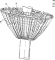
図4は三次元形状を例示するために、本発明によるタイヤ成形ドラムの第1位置にある一組のアームと、折返し装置の幾つかの部分とを斜視図で概略的に示し、また
図5は三次元形状を例示するために、本発明によるタイヤ成形ドラムの第2位置にある一組のアームと、折返し装置の幾つかの部分とを斜視図で概略的に示している。
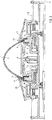
図1は未加硫タイヤを形成するための本発明による折返し装置を備えたタイヤ成形ドラムの長手方向の横断面を概略的に示している。この未加硫タイヤは、ゴム製または補強コードを有するタイヤ構成要素(図1では2つ、すなわち要素1,2が示されている)と、ハイビード充填ストリップを備えた2つのビードコアー3,4とを含んで成る。タイヤ構成要素の数および形式は製造される最終的なタイヤによって定まるもので、それらの可能な組立ておよび構造は当業者に周知であるので、これ以上の詳細な説明は省略する。
タイヤ成形ドラムは中央軸線5を有する。軸線5のまわりに互いに間隔を隔てて2つのリングセグメント6,7が配置されており、各々のリングセグメントはそれぞれ対応するビードコアー3,4を支持するようになっている。軸線5のまわりで各リングセグメント6,7の外側にアーム11,12で形成されたドラムセグメントが配置されており、これらのドラムセグメントはタイヤ構成要素1,2を支持するための円筒面を形成する。リングセグメント6,7が比較的幅の狭い補強ストリップ等の或る種のタイヤ構成要素を支持する機能も有するようにすることもできる。
図1はタイヤ成形ドラムの一例を示しており、この場合もリングセグメント間にドラムセグメント8,9,10を有している。既に知られているように、ドラムセグメント(特にドラムセグメント8)の少なくとも一部を半径方向へ移動させるための手段(図示されていない)と、リングセグメント3,4の間に位置するタイヤ構成要素の部分を例えば空気圧によって半径方向に膨張させるための手段(図示されていない)とが備えられている。
タイヤ成形ドラムは、リングセグメント6,7の両外側に、第1組を成し軸線方向に延在する枢動可能なアーム11,12をそれぞれ有する。各アーム11,12はそれぞれリングセグメント6,7に向かう端部を有しており、それら端部はそれぞれローラー13,14を有する。既に知られているように、第1組のアーム11,12のローラー13,14が実質的に閉じたリングを形成する第1位置(図1に示される)から、リングセグメント6,7の間に位置するタイヤ構成要素の膨張された部分をリングセグメント6,7の外側に位置するタイヤ構成要素の部分に対して押圧する第2位置(図2に示される)へ、第1組のアーム11,12のそれぞれを軸線方向且つ半径方向へ移動させるための手段(図2の15)が備えられる。
以下、本発明のタイヤ成形ドラムの基本的特徴すなわち折返し装置をさらに説明するが、当業者に十分周知であるタイヤ成形ドラムの他の部材は詳細に説明しない。
本発明によれば、折返し装置を備えたタイヤ成形ドラムが提供される。このタイヤ成形ドラムにおいて、第1組のアームの各々(11または12)は第2組の軸線方向に延在した枢動可能なアーム(図2および図4を参照すればそれぞれ17,19)を含む。第2組の各々のアーム17,19はそれぞれリングセグメント6,7に向かう端部を有し、その端部はそれぞれローラー16,18を有する。第2組の各アーム17,19の各々のローラー16,18は前記第1組における隣接する2つのアーム11,12の間に位置され、第2組における各々のローラー16,18は前記第1組のアーム11,12のローラー13,14の、リングセグメント6,7から離れる側に位置される。
さらに第2組のアーム17,19のローラー16,18が実質的に閉じたリングを形成する第1位置から、リングセグメント6,7の間に位置するタイヤ構成要素の膨張された部分をリングセグメント6,7の外側に位置するタイヤ構成要素の部分に対して押圧するための第2位置へ向けて、第2組のアームの各々を軸線方向且つ半径方向へ移動させるための手段、好ましくは手段15が備えられる。この組をなすアームを軸線方向且つ半径方向へ移動させるための手段は、第2位置から第1位置へアームを戻すように押圧するためにその組を成すアームのまわりに配置された可撓バンドを含むのが好ましい。
第2組のアーム17,19のローラー16,18は第1組のアーム11,12のローラー13,14の間に位置されているので、両組のローラーの第2位置においては、タイヤ部材のほとんど全周に沿う部分が互いに押圧され(図2および図5に示されるように)、この結果としてほぼ完全なタイヤ構成要素の付着が達成される。
図3は未加硫タイヤを成形するための本発明による折返し装置を備えたタイヤ成形ドラムの他の知られた実施例の長手方向の横断面(上側半分だけが示されており、下側半分は対称形である)を概略的に示している。この未加硫タイヤは、ゴム製または補強コードを有するタイヤ構成要素を含み、図3の右半分にその2つの補強コード1’,2’が示され、またハイビード充填ストリップを備えた2つのビードコアーを含み、その1つのビードコアー4’だけが示されている。このタイヤ成形ドラムは中央軸線5’を有する。軸線5’のまわりに互いに間隔を隔てて2つのリングセグメント6’,7’が配置されており、各々のリングセグメントはそれぞれ対応するビードコアーを支持する。リングセグメント6’,7’はまたタイヤ構成要素1’,2’を支持する作用もする。まず2組のアーム11’,17’および12’,19’は第1位置にあるときに、リングセグメントの外側のタイヤ構成要素の部分を支持するのに使用される。各アーム11’,12’(17’,19’)はそれぞれリングセグメント6’,7’に向いた端部を有し、その端部はそれぞれローラー13’,14’(16’,18’)を有する。一組のアームのローラーが実質的に閉じたリングを形成する第1位置(図3の左半分に示される)から、リングセグメント6’,7’の間に位置するタイヤ構成要素の膨張された部分をリングセグメント6’,7’の外側に位置するタイヤ構成要素の部分に押圧するための第2位置(図3の右半分に示される)へ向けて、組を成すアームの各々は移動されることができる。
第2組の各々のアーム17’,19’の各ローラー16’,18’は前記第1組における隣接する2つのアーム11’,12’の間に位置し、第2組の各々のローラー16’,18’は第1組のアーム11’,12’のローラー13’,14’の、リングセグメント6’,7’から離れる側に位置する。
第2組のアーム17’,19’のローラー16’,18’は第1組のアーム11’,12’のローラー13’,14’の間に位置されているので、両組のローラーの第2位置においては、タイヤ構成要素のほとんど全周に沿う部分が互いに押圧され、ゴム製スリーブを使用せずにほぼ完全なタイヤ構成要素部分の付着が達成される。
図3には1つのビードコアー4’が示されているが、ハイビード充填ストリップを有する前記2つのビードコアーを横方向に支持するために他の手段20,21(図3)が備えられている。この手段はリングセグメント6’,7’の間に位置される。前記手段は作動位置において、アームが第1位置から第2位置へ移動するときにハイビード充填ストリップを有するビードコアーをリングセグメントから押し出すのを防止する。ハイビード充填ストリップを有するビードコアーを横方向に支持するためのこの手段20,21は、非作動位置から作動位置へ向かって枢動できるのが好ましい。このようにして、ハイビード充填ストリップを有するビードコアーを横方向に支持するためのこの手段は、タイヤ成形ドラムの通常の作動の障害とならず、さらにタイヤ構成要素を初期位置に保持するのを補助することができる。The present invention relates to a tire molding comprising a turn-up apparatus for molding an unvulcanized tire having a tire component having a rubber or reinforcing cord and two bead cores with high bead filled strips. A drum having a central axis, two ring segments arranged around the axis and spaced apart from each other to support the bead core, and arranged outside each ring segment around the axis; A drum segment defining a circumferential surface for supporting the tire component and means for radially inflating the portion of the tire component located between the ring segments and disposed on both outer sides of the ring segment, each A first set of axially extending pivots having ends toward the ring segments, the ends having rollers A tire component in which the inflated portion of the tire member located between the ring segments is located outside the ring segments from a first position where the rollers of the first arm and the first set of arms form a substantially closed ring And a means for moving each of the first set of arms in the axial direction and in the radial direction toward a second position for pressing the portion.
Such a tire-forming drum with a folding device is known from British patent specification 1532960. This known tire shaping drum comprises two sets of arms, one set being located outside one ring segment and the other set being located outside the other ring segment. As the arm moves from the first position to the second position, the roller is moved a large distance from the axis so that the rollers are spaced apart from each other, thereby no longer forming a vertically closed ring. Since the second position is slightly further away from the central axis of the tire forming drum than the first position, the portion of the tire component located outside the ring segments is the portion of the tire component located between the ring segments. On the other hand, it is not fully pressed over the entire height, and the arm ends rise further apart from each other, resulting in incomplete circumferential pressure by the rollers. Rubber sleeves are provided around the arms to prevent incomplete adhesion of tire components that are detrimental to the quality of the tire being manufactured. However, this rubber sleeve has a limited life.
An object of the present invention is to form a tire with a turning device for forming an unvulcanized tire comprising a tire component having a rubber or reinforcing cord and two bead cores with high bead filling strips. Provided is a tire molding drum that can press tire component parts together along the entire circumference and height without using a rubber sleeve, thereby improving the final quality of the manufactured tire. That is.
For this purpose, a tire forming drum with a folding device of the type described above comprises, according to the invention, a first set of each arm including a second set of axially extending arms, The arms have ends toward the ring segments, each end has a roller, and the rollers of the second set of arms are each positioned between two adjacent arms of the first set, and the first set Of the tire components located between the ring segments from a first position where the second set of rollers forms a substantially closed ring, located on one side of the rollers of the arm A hand for moving each of the second set of arms axially and radially toward a second position for pressing the inflated portion against a portion of the tire component located outside the ring segment Given the characteristic that is provided. Since the rollers of the second set of arms are positioned between the first set of arms, the tire component parts are pressed against each other at least most of the entire circumference with both sets of rollers in the second position. As a result, at least almost complete adhesion is achieved.
A preferred embodiment of a tire forming drum with a turning device according to the invention comprises means for moving each of the first set of arms axially and radially, and each of the second set of arms axially and radially. The means for moving in the direction is formed by the same means. In this way, the folding device for the tire forming drum can be manufactured with a smaller design, and the movement of both sets of arms from the first position to the second position can be easily synchronized.
Another preferred embodiment of a tire design drum with a folding device according to the invention has means for laterally supporting two bead cores with high bead filling strips, which means are arranged between the ring segments. And preferably pivotable from a non-actuated position to an actuated position. In this way, when the arms are moved from the first position to the second position, the arms are prevented from pushing out the bead core with the high bead filling strips from those positions. When the means is pivoted from the non-actuated position to the actuated position, normal operation of the tire design drum is not adversely affected.
Several examples of a tire forming drum provided with a folding device according to the present invention will be described with reference to the drawings. In the drawing
FIG. 1 schematically shows a longitudinal cross section of a tire forming drum equipped with a folding device according to the present invention in a state where an arm is in a first position,
FIG. 2 is a schematic cross-sectional view in the longitudinal direction of a tire forming drum equipped with a folding device according to the invention, with the arm in the second position and the part of the tire component located between the ring segments inflated. Show,
FIG. 3 is a cross-sectional view in the longitudinal direction of another embodiment of a tire forming drum equipped with a folding device according to the present invention. The left half of the figure shows the arm in the first position, and the right half of the figure shows the arm Schematically shows a longitudinal cross section shown in a second position;
FIG. 4 schematically shows in perspective view a set of arms in a first position of a tire forming drum according to the invention and several parts of a folding device to illustrate the three-dimensional shape, and FIG. FIG. 1 schematically shows in perspective view a set of arms in a second position of a tire-forming drum according to the invention and several parts of a folding device to illustrate a three-dimensional shape.
FIG. 1 schematically shows a cross section in the longitudinal direction of a tire forming drum provided with a folding device according to the invention for forming an unvulcanized tire. This unvulcanized tire comprises a tire component having rubber or reinforcing cords (two in FIG. 1, ie elements 1 and 2), two
The tire forming drum has a
FIG. 1 shows an example of a tire forming drum, which also has
The tire forming drum has
Hereinafter, the basic features of the tire forming drum of the present invention, that is, the folding device will be further described, but other members of the tire forming drum that are well known to those skilled in the art are not described in detail.
According to the present invention, a tire molding drum provided with a folding device is provided. In this tire molding drum, each of the first set of arms (11 or 12) has a second set of axially extending arms (17 and 19, respectively referring to FIGS. 2 and 4). Including. Each
In addition, from the first position where the
Since the
FIG. 3 shows a longitudinal cross-section (only the upper half is shown, the lower half of another known embodiment of a tire-forming drum equipped with a folding device according to the invention for molding an unvulcanized tire. Is symmetrical). This unvulcanized tire includes a tire component having a rubber or reinforcing cord, the two reinforcing cords 1 ', 2' shown in the right half of FIG. 3 and two bead cores with high bead filling strips. And only one of its bead cores 4 'is shown. The tire molding drum has a
Each roller 16 ', 18' of each arm 17 ', 19' in the second set is located between two adjacent arms 11 ', 12' in the first set, and each
The rollers 16 ', 18' of the second set of arms 17 ', 19' are positioned between the rollers 13 ', 14' of the first set of arms 11 ', 12', so In the two positions, portions of the tire component along almost the entire circumference are pressed against each other, and almost complete attachment of the tire component portion is achieved without the use of a rubber sleeve.
Although one bead core 4 'is shown in FIG. 3, other means 20, 21 (FIG. 3) are provided to laterally support the two bead cores having high bead filling strips. This means is located between the ring segments 6 ', 7'. The means prevents, in the operating position, the pushing out of the bead core with the high bead filling strip from the ring segment as the arm moves from the first position to the second position. This means 20, 21 for laterally supporting the bead core with the high bead filling strip is preferably pivotable from the non-actuated position to the actuated position. In this way, this means for laterally supporting the bead core with the high bead filled strip does not interfere with the normal operation of the tire forming drum and further assists in maintaining the tire components in the initial position. be able to.
Claims (4)
Applications Claiming Priority (3)
| Application Number | Priority Date | Filing Date | Title |
|---|---|---|---|
| NL9700290 | 1997-05-23 | ||
| WO97/00290 | 1997-05-23 | ||
| PCT/NL1997/000435 WO1998052740A1 (en) | 1997-05-23 | 1997-07-22 | Tyre building drum with turn-up apparatus |
Publications (3)
| Publication Number | Publication Date |
|---|---|
| JP2001525748A JP2001525748A (en) | 2001-12-11 |
| JP2001525748A5 JP2001525748A5 (en) | 2005-01-13 |
| JP4124829B2 true JP4124829B2 (en) | 2008-07-23 |
Family
ID=19866189
Family Applications (1)
| Application Number | Title | Priority Date | Filing Date |
|---|---|---|---|
| JP55025898A Expired - Fee Related JP4124829B2 (en) | 1997-05-23 | 1997-07-22 | Tire forming drum with folding device |
Country Status (10)
| Country | Link |
|---|---|
| US (2) | US6318434B1 (en) |
| EP (1) | EP1001876B1 (en) |
| JP (1) | JP4124829B2 (en) |
| KR (1) | KR100559114B1 (en) |
| CN (1) | CN1074982C (en) |
| AU (1) | AU3466497A (en) |
| DE (1) | DE69716774T2 (en) |
| RU (1) | RU2189318C2 (en) |
| SK (1) | SK286587B6 (en) |
| WO (1) | WO1998052740A1 (en) |
Families Citing this family (30)
| Publication number | Priority date | Publication date | Assignee | Title |
|---|---|---|---|---|
| CN1120774C (en) * | 1999-07-30 | 2003-09-10 | 倍耐力轮胎公司 | Tyre assembling apparatus |
| US7152649B2 (en) | 1999-07-30 | 2006-12-26 | Pirelli Pneumatici S.P.A. | Tire-assembling apparatus |
| WO2001068356A1 (en) * | 2000-03-17 | 2001-09-20 | Vmi Epe Holland B.V. | Tyre building drum provided with a turn-up device |
| JP2003025461A (en) * | 2001-05-11 | 2003-01-29 | Fuji Seiko Kk | Tire molding apparatus and pneumatic radial tire |
| JP4651885B2 (en) * | 2001-09-12 | 2011-03-16 | 株式会社ブリヂストン | Tire molding drum |
| KR100441959B1 (en) * | 2001-12-28 | 2004-07-27 | 한국타이어 주식회사 | Carcass Building Drum Apparatus for Green Tire |
| JP3616613B2 (en) * | 2002-06-03 | 2005-02-02 | 株式会社市丸技研 | Winding device for tire member end in tire molding machine |
| CN100572040C (en) * | 2002-08-05 | 2009-12-23 | 株式会社普利司通 | Tire assembly drum and tire moulding method |
| NL1021668C2 (en) * | 2002-10-16 | 2004-04-20 | Vmi Epe Holland | Tire drum with storage mechanism for building an unvulcanized tire. |
| US7387697B2 (en) | 2003-02-07 | 2008-06-17 | Bridgestone Corporation | Method and apparatus for turning up tire structure members |
| US20050028920A1 (en) * | 2003-08-04 | 2005-02-10 | Roedseth John Kolbjoern | High crown first stage tire building drum |
| NL1026334C2 (en) * | 2004-06-04 | 2005-12-06 | Vmi Epe Holland | Tire drum assembly with storage mechanism for building an unvulcanized tire. |
| US7288160B2 (en) * | 2004-12-23 | 2007-10-30 | The Goodyear Tire & Rubber Company | Method of making a tire using a high crown uni-stage tire building drum |
| US20070068631A1 (en) * | 2005-09-28 | 2007-03-29 | Brian Painter | Tyre building drum |
| EP2032350B1 (en) * | 2006-06-29 | 2011-03-09 | Pirelli Tyre S.p.A. | Process and apparatus for manufacturing a pneumatic tyre |
| ATE553914T1 (en) | 2007-10-25 | 2012-05-15 | Fuji Seiko Co Ltd | DEVICE FOR FOLDING A CARCASS PLY |
| JP5219272B2 (en) * | 2008-01-28 | 2013-06-26 | 株式会社ブリヂストン | Tire molding equipment |
| KR101440897B1 (en) * | 2008-07-23 | 2014-09-17 | 피렐리 타이어 소시에떼 퍼 아찌오니 | Process and apparatus for manufacturing tyres for vehicle wheels |
| NL2003874C2 (en) | 2009-11-26 | 2011-05-30 | Vmi Holland Bv | TIRE CONSTRUCTION DRUM WITH STORAGE MECHANISM. |
| NL2011062C2 (en) | 2013-06-28 | 2015-01-05 | Vmi Holland Bv | Tyre building drum with a turn-up mechanism. |
| MX2016015083A (en) * | 2014-05-27 | 2017-02-28 | Pirelli | Process and apparatus for building tyres. |
| JP6445917B2 (en) * | 2015-04-13 | 2018-12-26 | 住友ゴム工業株式会社 | Raw tire molding equipment |
| KR101708894B1 (en) * | 2015-08-03 | 2017-02-22 | 한국타이어 주식회사 | Bead lock apparatus of greentire shaping drum machine |
| NL2018011B1 (en) * | 2016-12-16 | 2018-06-26 | Vmi Holland Bv | Drum half, tire building machine and method for operating said tire building machine |
| US20200207045A1 (en) | 2017-06-16 | 2020-07-02 | Harburg-Freudenberger Maschinenbau Gmbh | Method and apparatus for manufacturing tires |
| WO2020013969A1 (en) * | 2018-07-10 | 2020-01-16 | Bridgestone Americas Tire Operations, Llc | Modular tire turn-up apparatus |
| CN109291481B (en) * | 2018-11-30 | 2020-10-20 | 萨驰华辰机械(苏州)有限公司 | Position detection system and position detection method for tire building drum |
| WO2021094033A1 (en) * | 2019-11-15 | 2021-05-20 | Compagnie Generale Des Etablissements Michelin | Turnup of rubber products without beadwires |
| KR102425923B1 (en) | 2020-10-08 | 2022-07-28 | 금호타이어 주식회사 | The molding device of green tire |
| KR102516983B1 (en) * | 2021-08-19 | 2023-04-04 | 금호타이어 주식회사 | Tire building machine |
Family Cites Families (15)
| Publication number | Priority date | Publication date | Assignee | Title |
|---|---|---|---|---|
| FR95396E (en) * | 1966-02-25 | 1970-09-11 | Nrm Corp | Radial carcass tire making drum. |
| FR2093180A5 (en) | 1970-06-04 | 1972-01-28 | Gazuit Georges | Radial tyre forming drum |
| US3692605A (en) | 1970-07-22 | 1972-09-19 | Nrm Corp | Ply turn-up and side wall applying bladder for tire building machine and method |
| JPS5022074A (en) * | 1973-06-27 | 1975-03-08 | ||
| US4131500A (en) | 1974-12-09 | 1978-12-26 | Avon Tyres Limited | Tire building drum |
| GB1532960A (en) * | 1974-12-09 | 1978-11-22 | Avon Tyres Ltd | Tyre building drum |
| SU717851A1 (en) | 1978-06-16 | 1991-01-30 | Предприятие П/Я А-3404 | Device for assembling pneumatic tyres |
| US4309235A (en) * | 1980-07-09 | 1982-01-05 | National-Standard Company | Retractable bead setter assembly and method of operation thereof |
| US4362592A (en) * | 1981-04-09 | 1982-12-07 | The B. F. Goodrich Company | Ply turn-up means in a tire building machine |
| GB2182894B (en) * | 1985-11-13 | 1989-10-04 | Bates W & A Ltd | Tyre building apparatus |
| JPH0429835A (en) | 1990-05-28 | 1992-01-31 | Bridgestone Corp | Drum for molding of tire |
| SK45993A3 (en) | 1993-05-12 | 1995-06-07 | Matador As | Winding and back folding part of drum tire building |
| FR2708515A1 (en) | 1993-08-04 | 1995-02-10 | Michelin & Cie | Method and machine for making tires. |
| DE9405694U1 (en) | 1994-04-06 | 1994-05-26 | Schaeffler Waelzlager Kg | Rocker arm for a valve train of an internal combustion engine |
| JPH09309159A (en) * | 1996-05-21 | 1997-12-02 | Mitsubishi Heavy Ind Ltd | Take-up device for tire member end for tire molding drum |
-
1997
- 1997-07-22 EP EP97930899A patent/EP1001876B1/en not_active Expired - Lifetime
- 1997-07-22 AU AU34664/97A patent/AU3466497A/en not_active Abandoned
- 1997-07-22 SK SK1552-99A patent/SK286587B6/en not_active IP Right Cessation
- 1997-07-22 RU RU99124577/12A patent/RU2189318C2/en active
- 1997-07-22 US US09/380,561 patent/US6318434B1/en not_active Expired - Lifetime
- 1997-07-22 CN CN97182206A patent/CN1074982C/en not_active Ceased
- 1997-07-22 KR KR1019997010809A patent/KR100559114B1/en not_active IP Right Cessation
- 1997-07-22 JP JP55025898A patent/JP4124829B2/en not_active Expired - Fee Related
- 1997-07-22 DE DE69716774T patent/DE69716774T2/en not_active Expired - Lifetime
- 1997-07-22 WO PCT/NL1997/000435 patent/WO1998052740A1/en active IP Right Grant
-
2001
- 2001-06-18 US US09/882,261 patent/US20020124968A1/en not_active Abandoned
Also Published As
| Publication number | Publication date |
|---|---|
| CN1074982C (en) | 2001-11-21 |
| JP2001525748A (en) | 2001-12-11 |
| EP1001876A1 (en) | 2000-05-24 |
| KR20010012844A (en) | 2001-02-26 |
| US20020124968A1 (en) | 2002-09-12 |
| KR100559114B1 (en) | 2006-03-13 |
| CN1254307A (en) | 2000-05-24 |
| SK286587B6 (en) | 2009-01-07 |
| AU3466497A (en) | 1998-12-11 |
| DE69716774T2 (en) | 2004-12-30 |
| WO1998052740A1 (en) | 1998-11-26 |
| EP1001876B1 (en) | 2002-10-30 |
| SK155299A3 (en) | 2000-05-16 |
| RU2189318C2 (en) | 2002-09-20 |
| US6318434B1 (en) | 2001-11-20 |
| DE69716774D1 (en) | 2002-12-05 |
Similar Documents
| Publication | Publication Date | Title |
|---|---|---|
| JP4124829B2 (en) | Tire forming drum with folding device | |
| JP4429162B2 (en) | Tire molding method and tire molding drum | |
| JP6258627B2 (en) | Sleeveless tire molding drum | |
| JP6250328B2 (en) | Sleeveless tire building drum with replaceable width member | |
| JP2011504428A (en) | Tire assembling method and tire assembling drum | |
| KR100982726B1 (en) | Tyre drum with turn-up mechanism for building an unvulcanized tyre | |
| EP0459728A2 (en) | Tire forming drum | |
| JP3228771B2 (en) | Combination of tire building drum and elastic bladder | |
| US20020104620A1 (en) | Tyre-assembling apparatus | |
| JP2002052623A (en) | Tire constructing drum | |
| JP7040045B2 (en) | Presser for tire molding | |
| GB1574654A (en) | Manufacture of pneumatic tyres | |
| JP2019077079A (en) | Green tire manufacturing method | |
| JP6450207B2 (en) | Pneumatic tire manufacturing method | |
| JPS6235389B2 (en) | ||
| JP2018114646A (en) | Tire molding apparatus | |
| JP6736961B2 (en) | Groove forming device | |
| JPS6249180B2 (en) | ||
| JP4440512B2 (en) | Pneumatic tire manufacturing method and pneumatic tire | |
| JP2006503727A (en) | Manufacturing method and apparatus for vehicle wheel tire | |
| JPH0445338B2 (en) | ||
| JP2006224521A (en) | Tire molding machine | |
| JP2003025461A (en) | Tire molding apparatus and pneumatic radial tire | |
| JP2006503728A (en) | Manufacturing method and apparatus for vehicle wheel tire | |
| JPS6330854B2 (en) |
Legal Events
| Date | Code | Title | Description |
|---|---|---|---|
| A621 | Written request for application examination |
Free format text: JAPANESE INTERMEDIATE CODE: A621 Effective date: 20040128 |
|
| A521 | Written amendment |
Free format text: JAPANESE INTERMEDIATE CODE: A523 Effective date: 20040331 |
|
| A131 | Notification of reasons for refusal |
Free format text: JAPANESE INTERMEDIATE CODE: A131 Effective date: 20060711 |
|
| A521 | Written amendment |
Free format text: JAPANESE INTERMEDIATE CODE: A523 Effective date: 20061011 |
|
| A131 | Notification of reasons for refusal |
Free format text: JAPANESE INTERMEDIATE CODE: A131 Effective date: 20070403 |
|
| A601 | Written request for extension of time |
Free format text: JAPANESE INTERMEDIATE CODE: A601 Effective date: 20070703 |
|
| A602 | Written permission of extension of time |
Free format text: JAPANESE INTERMEDIATE CODE: A602 Effective date: 20070820 |
|
| A521 | Written amendment |
Free format text: JAPANESE INTERMEDIATE CODE: A523 Effective date: 20070802 |
|
| TRDD | Decision of grant or rejection written | ||
| A01 | Written decision to grant a patent or to grant a registration (utility model) |
Free format text: JAPANESE INTERMEDIATE CODE: A01 Effective date: 20080408 |
|
| A01 | Written decision to grant a patent or to grant a registration (utility model) |
Free format text: JAPANESE INTERMEDIATE CODE: A01 |
|
| A61 | First payment of annual fees (during grant procedure) |
Free format text: JAPANESE INTERMEDIATE CODE: A61 Effective date: 20080507 |
|
| R150 | Certificate of patent or registration of utility model |
Free format text: JAPANESE INTERMEDIATE CODE: R150 |
|
| FPAY | Renewal fee payment (event date is renewal date of database) |
Free format text: PAYMENT UNTIL: 20110516 Year of fee payment: 3 |
|
| FPAY | Renewal fee payment (event date is renewal date of database) |
Free format text: PAYMENT UNTIL: 20120516 Year of fee payment: 4 |
|
| FPAY | Renewal fee payment (event date is renewal date of database) |
Free format text: PAYMENT UNTIL: 20130516 Year of fee payment: 5 |
|
| FPAY | Renewal fee payment (event date is renewal date of database) |
Free format text: PAYMENT UNTIL: 20130516 Year of fee payment: 5 |
|
| R250 | Receipt of annual fees |
Free format text: JAPANESE INTERMEDIATE CODE: R250 |
|
| R250 | Receipt of annual fees |
Free format text: JAPANESE INTERMEDIATE CODE: R250 |
|
| R250 | Receipt of annual fees |
Free format text: JAPANESE INTERMEDIATE CODE: R250 |
|
| R250 | Receipt of annual fees |
Free format text: JAPANESE INTERMEDIATE CODE: R250 |
|
| LAPS | Cancellation because of no payment of annual fees |