RU2183875C2 - Technology of manufacture of superconductive wire - Google Patents
Technology of manufacture of superconductive wire Download PDFInfo
- Publication number
- RU2183875C2 RU2183875C2 RU99121644/09A RU99121644A RU2183875C2 RU 2183875 C2 RU2183875 C2 RU 2183875C2 RU 99121644/09 A RU99121644/09 A RU 99121644/09A RU 99121644 A RU99121644 A RU 99121644A RU 2183875 C2 RU2183875 C2 RU 2183875C2
- Authority
- RU
- Russia
- Prior art keywords
- tube
- metal tube
- metal
- superconductive
- metal oxide
- Prior art date
Links
Images
Classifications
-
- H—ELECTRICITY
- H01—ELECTRIC ELEMENTS
- H01B—CABLES; CONDUCTORS; INSULATORS; SELECTION OF MATERIALS FOR THEIR CONDUCTIVE, INSULATING OR DIELECTRIC PROPERTIES
- H01B12/00—Superconductive or hyperconductive conductors, cables, or transmission lines
-
- H—ELECTRICITY
- H01—ELECTRIC ELEMENTS
- H01F—MAGNETS; INDUCTANCES; TRANSFORMERS; SELECTION OF MATERIALS FOR THEIR MAGNETIC PROPERTIES
- H01F41/00—Apparatus or processes specially adapted for manufacturing or assembling magnets, inductances or transformers; Apparatus or processes specially adapted for manufacturing materials characterised by their magnetic properties
- H01F41/02—Apparatus or processes specially adapted for manufacturing or assembling magnets, inductances or transformers; Apparatus or processes specially adapted for manufacturing materials characterised by their magnetic properties for manufacturing cores, coils, or magnets
- H01F41/04—Apparatus or processes specially adapted for manufacturing or assembling magnets, inductances or transformers; Apparatus or processes specially adapted for manufacturing materials characterised by their magnetic properties for manufacturing cores, coils, or magnets for manufacturing coils
- H01F41/048—Superconductive coils
-
- H—ELECTRICITY
- H10—SEMICONDUCTOR DEVICES; ELECTRIC SOLID-STATE DEVICES NOT OTHERWISE PROVIDED FOR
- H10N—ELECTRIC SOLID-STATE DEVICES NOT OTHERWISE PROVIDED FOR
- H10N60/00—Superconducting devices
- H10N60/01—Manufacture or treatment
- H10N60/0268—Manufacture or treatment of devices comprising copper oxide
- H10N60/0801—Processes peculiar to the manufacture or treatment of filaments or composite wires
-
- Y—GENERAL TAGGING OF NEW TECHNOLOGICAL DEVELOPMENTS; GENERAL TAGGING OF CROSS-SECTIONAL TECHNOLOGIES SPANNING OVER SEVERAL SECTIONS OF THE IPC; TECHNICAL SUBJECTS COVERED BY FORMER USPC CROSS-REFERENCE ART COLLECTIONS [XRACs] AND DIGESTS
- Y10—TECHNICAL SUBJECTS COVERED BY FORMER USPC
- Y10T—TECHNICAL SUBJECTS COVERED BY FORMER US CLASSIFICATION
- Y10T29/00—Metal working
- Y10T29/49—Method of mechanical manufacture
- Y10T29/49002—Electrical device making
- Y10T29/49014—Superconductor
Abstract
Description
Изобретение относится к способу изготовления сверхпроводящей проволоки конечной длины, предусматривающему, по меньшей мере, ввод исходного сверхпроводящего материала в металлическую трубку и последующее укладывание или свертывание металлической трубки, например в спираль, таким образом, что первая часть наружной поверхности трубки соприкасается со второй частью этой поверхности трубки, после чего металлическую трубку, заполненную исходным сверхпроводящим материалом, нагревают до температуры, близкой к точке плавления металлической трубки, для того, чтобы сформировать в исходном материале сверхпроводящую фазу. The invention relates to a method for manufacturing a superconducting wire of finite length, comprising at least introducing a source of superconducting material into a metal tube and then folding or rolling a metal tube, for example into a spiral, so that the first part of the outer surface of the tube is in contact with the second part of this surface tube, after which the metal tube filled with the starting superconducting material is heated to a temperature close to the melting point of the metal th tube, in order to form a superconducting phase in the starting material.
Данный способ, который является обычным при производстве сверхпроводниковой проволоки конечной длины, обеспечивает формирование трубки, обладающей подходящими механическими свойствами, в которой заключен сверхпроводящий материал. При этом сверхпроводящий материал может формироваться, например, из порошкового материала, который, будучи введенным в трубку, еще не придает проволоке сверхпроводимость, но который активируется после последующей термообработки, в результате чего проволока и становится сверхпроводящей. This method, which is common in the manufacture of a superconducting wire of finite length, provides the formation of a tube having suitable mechanical properties in which the superconducting material is enclosed. In this case, the superconducting material can be formed, for example, from a powder material, which, when introduced into the tube, does not yet impart superconductivity to the wire, but which is activated after subsequent heat treatment, as a result of which the wire becomes superconducting.
Однако указанная термообработка связана с проблемой, состоящей в том, что, из практических соображений значительно легче производить заполнение или укладку проводника (с целью сделать его более удобным в обращении) до того, как он подвергнут термообработке. Однако, как следствие последующей термообработки, может оказаться, что уложенную или свернутую в спираль проволоку невозможно развернуть или размотать, поскольку участки проволоки скрепляются друг с другом в зонах, где первая часть наружной поверхности трубки соприкасается с ее второй частью. However, this heat treatment is associated with the problem that, for practical reasons, it is much easier to fill or lay the conductor (in order to make it more convenient to handle) before it is subjected to heat treatment. However, as a result of the subsequent heat treatment, it may turn out that the wire laid or coiled cannot be unwrapped or unwound, since sections of the wire are fastened to each other in areas where the first part of the outer surface of the tube is in contact with its second part.
Известное решение этой проблемы заключается в использовании на этапе свертывания проволоки в спираль перед ее термообработкой керамической ленты, которая свертывается вместе с проволокой таким образом, что никакие участки проволоки по ее длине не контактируют в процессе свертывания с другими ее участками. В результате последующее разматывание термообработанной проволоки может быть выполнено без какого-либо риска того, что произошло скрепление каких-либо участков сверхпроводящей проволоки. A well-known solution to this problem is to use a ceramic tape at the stage of coiling the wire before it is heat-treated, which coils together with the wire so that no sections of the wire come into contact with other sections along the length of the wire. As a result, the subsequent unwinding of the heat-treated wire can be performed without any risk that any sections of the superconducting wire have been bonded.
Документ ЕР А 244144 описывает способ, согласно которому проволока покрывается по ее длине изолирующим слоем, состоящим из силиката и еще одного компонента, способного вступать в реакцию с указанным силикатом с образованием керамического слоя при нагреве до температур свыше 500oС, после чего слой высушивают и подвергают термообработке при указанной температуре для формирования изолирующего керамического материала.EPA 244144 describes a method in which a wire is coated along its length with an insulating layer consisting of silicate and another component capable of reacting with said silicate to form a ceramic layer when heated to temperatures above 500 ° C. , after which the layer is dried and subjected to heat treatment at the specified temperature to form an insulating ceramic material.
Поскольку изолирующий слой формирует изолирующую поверхность, которая при указанных температурах является вязкой, данный способ непригоден для термообработки сверхпроводящей проволоки, которая была свернута, например, в спираль и которая затем должна быть размотана из указанной спирали для дальнейшего использования. Since the insulating layer forms an insulating surface that is viscous at the indicated temperatures, this method is not suitable for heat treatment of a superconducting wire that has been rolled up, for example, into a spiral and which then needs to be unwound from the specified spiral for further use.
Из документа JP 09082146-А известен способ изготовления сверхпроводящей проволоки конечной длины с покрытием из оксида никеля или оксида циркония, предусматривающий размещение трубки из серебра, заполненной исходным сверхпроводящим материалом, в наружную трубку из никеля или циркония, после чего обе трубки раскатывают до по существу круглой проволоки меньшего диаметра, которую затем прокатывают и подвергают термообработке таким образом, чтобы получить в исходном сверхпроводящем материале сверхпроводящую фазу, причем указанная наружная трубка формирует слой оксида никеля или оксида циркония. JP 09082146-A discloses a method for manufacturing a finite-length superconducting wire coated with nickel or zirconia, comprising placing a silver tube filled with the starting superconducting material in an outer nickel or zirconia tube, after which both tubes are rolled into a substantially round wires of a smaller diameter, which are then rolled and heat-treated in such a way as to obtain a superconducting phase in the starting superconducting material, said outer t cutting forms a layer of nickel oxide or zirconium oxide.
Трубка, полученная данным способом, может очень хорошо свертываться, например в спираль, причем участки наружного покрытия не скрепляются друг с другом при возможной последующей термообработке, однако известный способ требует осуществлять довольно точный технологический контроль для того, чтобы обеспечить приемлемо однородную толщину наружного слоя оксида металла, особенно если желательно добиться очень малой толщины этого наружного слоя. The tube obtained by this method can coagulate very well, for example, into a spiral, and the sections of the outer coating are not bonded to each other during possible subsequent heat treatment, however, the known method requires fairly accurate technological control in order to ensure an acceptable uniform thickness of the outer layer of metal oxide , especially if it is desirable to achieve a very small thickness of this outer layer.
Таким образом, проблемы, связанные с известными способами, заключаются в том, что керамическая лента неудобна в обращении, тогда как значительная толщина изолирующего слоя приводит к тому, что проволока, соответствующая заданной длине проводника, приобретает относительно большие размеры. Thus, the problems associated with the known methods are that the ceramic tape is inconvenient to handle, while the significant thickness of the insulating layer causes the wire corresponding to a given length of the conductor to become relatively large.
Задачей настоящего изобретения является создание способа изготовления сверхпроводящей проволоки конечной длины, типа охарактеризованного в первом параграфе данного описания, осуществление которого не требует применения керамической ленты для того, чтобы разделить отдельные слои проводника, еще не подвергшегося термообработке, при укладывании или свертывании проволоки в спираль, т. е. создание способа, позволяющего производить термообработку сверхпроводящей проволоки в компактной форме, например, свернутой в спираль, после которой сверхпроводящая проволока может быть снова размотана для использования в производственном процессе. The objective of the present invention is to provide a method for manufacturing a superconducting wire of finite length, such as described in the first paragraph of this description, the implementation of which does not require the use of ceramic tape in order to separate the individual layers of a conductor that has not undergone heat treatment, when laying or coiling the wire in a spiral, t i.e., creating a method that allows heat treatment of a superconducting wire in a compact form, for example, coiled into a spiral, after which verhprovodyaschaya wire may be unwound again for use in the manufacturing process.
Поставленная задача достигнута, в соответствии с настоящим изобретением, за счет того, что на металлическую трубку, перед ее укладкой или свертыванием наносят жидкое покрытие, по меньшей мере, на первую и вторую части ее наружной поверхности, причем указанное покрытие содержит по существу жидкий компонент, который полностью испаряется или выгорает при температуре, при которой происходит формирование сверхпроводящей фазы в сверхпроводящем материале, и порошковый материал, суспендированный в жидком компоненте и имеющий температуру плавления, превышающую температуру плавления металлической трубки. The object is achieved, in accordance with the present invention, due to the fact that the metal tube, before it is laid or curled, is applied a liquid coating to at least the first and second parts of its outer surface, said coating containing a substantially liquid component, which completely evaporates or burns out at a temperature at which the formation of a superconducting phase in the superconducting material occurs, and a powder material suspended in a liquid component and having a melting temperature eniya exceeding the melting temperature of the metal tube.
Тем самым обеспечивается образование очень тонкого слоя материала на поверхности проводника, еще не подвергшегося термообработке, и благодаря этому слою при укладывании или свертывании металлической трубки ее первая часть наружной поверхности не будет соприкасаться со второй частью наружной поверхности во время термообработки, причем свернутая, например в спираль, проволока не становится очень громоздкой. This ensures the formation of a very thin layer of material on the surface of the conductor, not yet subjected to heat treatment, and thanks to this layer, when laying or folding a metal tube, its first part of the outer surface will not come into contact with the second part of the outer surface during heat treatment, and it will be rolled up, for example, into a spiral The wire does not get very bulky.
В предпочтительном варианте осуществления изобретения покрытие, наносимое на проволоку, содержит керамический материал, желательно оксид металла, предпочтительно выбранный из группы, состоящей из Аl2O3, Сr2О3, СuхОу, NixOy, ZnxOy, ТахОу.In a preferred embodiment of the invention, the coating applied to the wire comprises a ceramic material, preferably metal oxide, preferably selected from the group consisting of Al 2 O 3 , Cr 2 O 3 , Cu x O y , Ni x O y , Zn x O y , Ta x Oh y .
В одном из вариантов покрытие может быть сформировано нанесением порошка оксида металла. Особенно просто нанести его в виде краски, состоящей из жидкой среды, в которой суспензирован порошок оксида металла. In one embodiment, the coating may be formed by applying a metal oxide powder. It is especially simple to apply it in the form of a paint consisting of a liquid medium in which a metal oxide powder is suspended.
В этом случае желательно, чтобы порошок оксида металла был суспендирован с концентрацией, при которой отдельные частицы оксида металла, будучи нанесенными на первую и вторую части наружной поверхности металлической трубки, располагались бы с такой плотностью, что частицы оксида металла на первой части наружной поверхности металлической трубки не соприкасались бы со второй частью наружной поверхности металлической трубки и наоборот. In this case, it is desirable that the metal oxide powder be suspended with a concentration at which individual metal oxide particles, when deposited on the first and second parts of the outer surface of the metal tube, are so dense that the metal oxide particles on the first part of the outer surface of the metal tube would not come into contact with the second part of the outer surface of the metal tube and vice versa.
Желательно также, чтобы жидкая среда, в которой суспендируется порошкообразный оксид металла, содержала растворитель, такой как ацетон, спирт или толуол, смешанный с некоторым количеством полимера, такого как поливинилбутираль (ПВБ). Поливинилбутираль рекомендуется добавлять в количестве от 0,1 до 10% по весу, предпочтительно от 1 до 4% по весу, поскольку такое содержание обеспечивает хорошие адгезионные свойства жидкой среды в отношении суспензированного порошка оксида металла. It is also desirable that the liquid medium in which the powdered metal oxide is suspended contains a solvent such as acetone, alcohol or toluene mixed with some polymer such as polyvinyl butyral (PVB). Polyvinyl butyral is recommended to be added in an amount of from 0.1 to 10% by weight, preferably from 1 to 4% by weight, since such a content provides good adhesive properties of the liquid medium in relation to the suspended metal oxide powder.
Проведенные испытания показали, что в качестве порошкообразного оксида металла предпочтительно использовать оксид циркония, однако другие керамические порошки, особенно порошкообразные оксиды металлов, также могут иметь применение. The tests showed that it is preferable to use zirconium oxide as a powdered metal oxide, however, other ceramic powders, especially powdered metal oxides, can also be used.
Настоящее изобретение далее будет подробнее описано со ссылками на прилагаемые чертежи, где
на фиг. 1 дан общий вид свернутого в спираль проводника, содержащего сверхпроводящий материал;
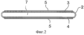
на фиг. 2 схематично изображено поперечное сечение проводника по фиг.1 согласно первому варианту выполнения;
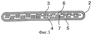
на фиг. 3 схематично изображено поперечное сечение проводника по фиг.1 согласно второму варианту выполнения.The present invention will now be described in more detail with reference to the accompanying drawings, where
in FIG. 1 is a general view of a coiled conductor containing superconducting material;
in FIG. 2 is a schematic cross-sectional view of the conductor of FIG. 1 according to a first embodiment;
in FIG. 3 is a schematic cross-sectional view of the conductor of FIG. 1 according to a second embodiment.
На фиг.1 представлен проводник, содержащий сверхпроводящий материал. Как можно видеть, проводник намотан на сердечник с целью его последующей термообработки. 1 shows a conductor containing superconducting material. As you can see, the conductor is wound on the core for the purpose of its subsequent heat treatment.
Намотанный таким образом проводник может быть изготовлен согласно известному способу, предусматривающему заполнение трубки 2 сверхпроводящим материалом 7 с последующим вытягиванием, раскаткой или каким-либо другим видом механической обработки для того, чтобы уменьшить поперечные размеры трубки 2. Предпочтительно этот процесс механической обработки включает прокатку или другую операцию, позволяющую получить проводник в форме ленты, имеющей желаемую толщину. Процессы такого типа хорошо известны из литературы и поэтому не будут описываться подробно. The conductor wound in this way can be made according to a known method, comprising filling the
Достаточно сказать, что получаемый продукт представляет собой проводник, содержащий исходный сверхпроводящий материал, который требует дальнейшей термообработки для формирования в исходном материале сверхпроводящей фазы. Suffice it to say that the resulting product is a conductor containing the starting superconducting material, which requires further heat treatment to form a superconducting phase in the starting material.
Благодаря соответствующей обработке проводника он оказывается свернутым или уложенным, например, в спираль 1, как это показано на фиг.1, после чего может начинаться его термообработка. Due to the corresponding processing of the conductor, it turns out to be rolled up or laid, for example, in a spiral 1, as shown in Fig. 1, after which its heat treatment can begin.
Термообработка часто требует использования температур, близких к температуре плавления трубки 2, так что если свернутый проводник 1 имеет касающиеся друг друга поверхности 3, 4, как это показано на фиг.2, то поверхность 3 трубки, вероятно, расплавится вместе с прилежащей поверхностью 4 проводника. Heat treatment often requires the use of temperatures close to the melting temperature of the
В соответствии с настоящим изобретением эта опасность устраняется благодаря тому, что, как это иллюстрируется фиг.2 и 3, перед укладыванием трубки 2 в спираль или каким-либо другим образом для предстоящей термообработки на нее наносится покрытие 5, температура плавления которого выше температуры плавления материала, из которого выполнена трубка 2. In accordance with the present invention, this danger is eliminated by the fact that, as illustrated in FIGS. 2 and 3, before laying the
На фиг.2, таким образом, представлен первый вариант выполнения настоящего изобретения, согласно которому сама трубка 2 заключает в себе исходный сверхпроводящий материал, тогда как на части 3, 4 ее поверхности нанесено покрытие 5 из керамического материала, выбранного из группы материалов, имеющих общую формулу МхОу, где М - это металл, такой как Сu, Ni, Al, Zn, Zr, Sr, Mn, Та и т.д., а О - это кислород.Figure 2, thus, presents a first embodiment of the present invention, according to which the
Согласно предпочтительным вариантам способа по изобретению покрытие 5 может быть нанесено в виде краски, которая содержит желательный керамический материал, суспендированный в жидкости, такой как растворитель, представляющий собой ацетон, спирт или толуол, смешанный с некоторым количеством полимера, такого как поливинилбутираль (ПВБ). According to preferred embodiments of the method of the invention,
Альтернативно, керамическое покрытие 5 может быть нанесено в форме порошка или же оно может быть сформировано простым окислением материала трубки 2. Alternatively, the
На фиг.3 представлен второй вариант осуществления изобретения, согласно которому трубка 2 заполнена множеством нитевидных трубок 6, которые, в свою очередь, наполнены исходным сверхпроводящим материалом 7. Как и в варианте, проиллюстрированном фиг.2, проводник, изображенный на фиг.3, снабжен керамическим покрытием 5, однако, в этом случае, в отличие от предыдущего варианта, покрытие нанесено таким образом, что оно полностью охватывает всю наружную поверхность трубки 2. Figure 3 presents a second embodiment of the invention, according to which the
Очевидно, что, опираясь на основную идею настоящего изобретения, специалист в данной области будет способен предложить другие варианты проводников, которые снабжены покрытием для предотвращения расплавления свернутого проводника. Так, настоящее изобретение может быть применено к проводникам, имеющим поперечное сечение, отличное от представленных на фиг.2 и 3, как в отношении наружных размеров, так и внутренней структуры трубки. Obviously, based on the basic idea of the present invention, a person skilled in the art will be able to propose other versions of conductors that are coated to prevent melting of the rolled conductor. Thus, the present invention can be applied to conductors having a cross-section different from those shown in FIGS. 2 and 3, both with respect to the external dimensions and the internal structure of the tube.
Claims (5)
Applications Claiming Priority (2)
| Application Number | Priority Date | Filing Date | Title |
|---|---|---|---|
| DK0340/97 | 1997-03-25 | ||
| DK34097 | 1997-03-25 |
Publications (2)
| Publication Number | Publication Date |
|---|---|
| RU99121644A RU99121644A (en) | 2001-11-20 |
| RU2183875C2 true RU2183875C2 (en) | 2002-06-20 |
Family
ID=8092421
Family Applications (1)
| Application Number | Title | Priority Date | Filing Date |
|---|---|---|---|
| RU99121644/09A RU2183875C2 (en) | 1997-03-25 | 1998-03-25 | Technology of manufacture of superconductive wire |
Country Status (14)
| Country | Link |
|---|---|
| US (1) | US6223418B1 (en) |
| EP (1) | EP0970483B1 (en) |
| JP (1) | JP2001516495A (en) |
| KR (1) | KR20000076104A (en) |
| CN (1) | CN1126118C (en) |
| AT (1) | ATE241205T1 (en) |
| AU (1) | AU727072B2 (en) |
| CA (1) | CA2284782A1 (en) |
| DE (1) | DE69814842T2 (en) |
| NO (1) | NO994666L (en) |
| NZ (1) | NZ337593A (en) |
| RU (1) | RU2183875C2 (en) |
| SK (1) | SK118299A3 (en) |
| WO (1) | WO1998043253A1 (en) |
Cited By (1)
| Publication number | Priority date | Publication date | Assignee | Title |
|---|---|---|---|---|
| US8216979B2 (en) | 2006-02-16 | 2012-07-10 | Sumitomo Electric Industries, Ltd. | Method of manufacturing superconducting thin film material, superconducting device and superconducting thin film material |
Families Citing this family (3)
| Publication number | Priority date | Publication date | Assignee | Title |
|---|---|---|---|---|
| KR100412077B1 (en) * | 2001-08-14 | 2003-12-24 | 한국기계연구원 | The thermal barrier coating solution for high temperature superconducting long wire and the synthesis method of the same |
| DE102004040754A1 (en) * | 2004-08-23 | 2006-03-09 | Siemens Ag | Rectangular coil of ribbon-shaped superconductors with HochTc superconductor material and use thereof |
| DE102009028174A1 (en) * | 2009-07-31 | 2011-02-03 | Bruker Hts Gmbh | Producing powder-in-tube-high-temperature superconductor-wire with noble metal sheath made of silver/silver alloy, by coating semi-finished product of wire with separating agent, and applying aqueous suspension of agent on product surface |
Family Cites Families (9)
| Publication number | Priority date | Publication date | Assignee | Title |
|---|---|---|---|---|
| US3873799A (en) * | 1973-10-19 | 1975-03-25 | Kabel Metallwerke Ghh | Method of making a composite superconducting tube |
| DE3168609D1 (en) * | 1980-07-15 | 1985-03-14 | Imi Kynoch Ltd | Flexible insulation for filamentary intermetallic superconductor wire |
| CA1331559C (en) * | 1986-04-21 | 1994-08-23 | Jon Joseph Kabara | Antimicrobial preservative compositions and methods |
| JPS6413706A (en) * | 1987-07-08 | 1989-01-18 | Furukawa Electric Co Ltd | Manufacture of superconducting coil |
| EP0304116A1 (en) * | 1987-08-12 | 1989-02-22 | Koninklijke Philips Electronics N.V. | Method of manufacturing a superconductive wire or cable |
| JP2519742B2 (en) * | 1987-08-28 | 1996-07-31 | 住友電気工業株式会社 | Manufacturing method of superconducting material |
| JPH01158754A (en) * | 1987-12-15 | 1989-06-21 | Fujitsu Ltd | Manufacture of superconductor element |
| GB2256080A (en) * | 1991-05-20 | 1992-11-25 | Marconi Gec Ltd | Superconductive electrical conductor. |
| JPH0982146A (en) | 1995-09-08 | 1997-03-28 | Kobe Steel Ltd | Oxide superconducting wire and its manufacture |
-
1998
- 1998-03-25 JP JP54091498A patent/JP2001516495A/en active Pending
- 1998-03-25 KR KR19997008192A patent/KR20000076104A/en not_active Application Discontinuation
- 1998-03-25 CN CN98803697A patent/CN1126118C/en not_active Expired - Fee Related
- 1998-03-25 CA CA002284782A patent/CA2284782A1/en not_active Abandoned
- 1998-03-25 NZ NZ337593A patent/NZ337593A/en unknown
- 1998-03-25 RU RU99121644/09A patent/RU2183875C2/en not_active IP Right Cessation
- 1998-03-25 WO PCT/DK1998/000120 patent/WO1998043253A1/en not_active Application Discontinuation
- 1998-03-25 AU AU66127/98A patent/AU727072B2/en not_active Ceased
- 1998-03-25 DE DE69814842T patent/DE69814842T2/en not_active Expired - Fee Related
- 1998-03-25 AT AT98907923T patent/ATE241205T1/en not_active IP Right Cessation
- 1998-03-25 SK SK1182-99A patent/SK118299A3/en unknown
- 1998-03-25 US US09/380,115 patent/US6223418B1/en not_active Expired - Fee Related
- 1998-03-25 EP EP98907923A patent/EP0970483B1/en not_active Expired - Lifetime
-
1999
- 1999-09-24 NO NO994666A patent/NO994666L/en unknown
Cited By (1)
| Publication number | Priority date | Publication date | Assignee | Title |
|---|---|---|---|---|
| US8216979B2 (en) | 2006-02-16 | 2012-07-10 | Sumitomo Electric Industries, Ltd. | Method of manufacturing superconducting thin film material, superconducting device and superconducting thin film material |
Also Published As
| Publication number | Publication date |
|---|---|
| WO1998043253A1 (en) | 1998-10-01 |
| SK118299A3 (en) | 2000-12-11 |
| CA2284782A1 (en) | 1998-10-01 |
| AU6612798A (en) | 1998-10-20 |
| ATE241205T1 (en) | 2003-06-15 |
| NZ337593A (en) | 2000-04-28 |
| EP0970483B1 (en) | 2003-05-21 |
| CN1126118C (en) | 2003-10-29 |
| EP0970483A1 (en) | 2000-01-12 |
| NO994666D0 (en) | 1999-09-24 |
| KR20000076104A (en) | 2000-12-26 |
| DE69814842D1 (en) | 2003-06-26 |
| CN1251201A (en) | 2000-04-19 |
| AU727072B2 (en) | 2000-11-30 |
| DE69814842T2 (en) | 2004-02-26 |
| JP2001516495A (en) | 2001-09-25 |
| US6223418B1 (en) | 2001-05-01 |
| NO994666L (en) | 1999-09-24 |
Similar Documents
| Publication | Publication Date | Title |
|---|---|---|
| US5798678A (en) | Superconducting wind-and-react-coils and methods of manufacture | |
| US6387852B1 (en) | Method of applying high temperature compatible insulation to superconductors | |
| RU2183875C2 (en) | Technology of manufacture of superconductive wire | |
| US2718049A (en) | Method of manufacturing bundles of very thin magnetic wires | |
| US4761520A (en) | Spiral wrapped insulated magnet wire | |
| AU1376400A (en) | A method of producing a superconducting tape | |
| JPH01134811A (en) | Extremely low temperature cable | |
| JP3635210B2 (en) | Oxide superconducting compression molded conductor and manufacturing method thereof | |
| US6387525B1 (en) | Self insulating substrate tape | |
| RU99121644A (en) | METHOD FOR PRODUCING SUPERCONDUCTING WIRE | |
| JPH06243745A (en) | Manufacture of high temperature superconducting wire material and high temperature superconducting coil | |
| JP2617227B2 (en) | Method for producing coiled oxide superconducting raw material | |
| JPH01251519A (en) | Insulation process for oxide superconductive wire | |
| JPS62206706A (en) | Manufacture of insulated wire and heat resistant insulated coil using the wire | |
| JPH04292808A (en) | Multicore superconductive wire | |
| JPH02177304A (en) | Manufacture of superconducting oxide solenoid | |
| JPS54131791A (en) | Lead wire | |
| JPH0191403A (en) | Manufacture of oxide superconducting coil | |
| JPH0410507A (en) | Oxide superconducting coil | |
| JPS62106607A (en) | Compound superconductive coil | |
| JPH02270222A (en) | Ceramic superconducting wire and manufacture thereof | |
| JPH05144626A (en) | Insulating material for superconducting oxide wire and manufacture of insulated wire | |
| JPH02271509A (en) | Manufacture of wound magnetic core | |
| JPH02246101A (en) | Oxide superconductive coil | |
| JPS6328019A (en) | Manufacture of insulating coil |
Legal Events
| Date | Code | Title | Description |
|---|---|---|---|
| MM4A | The patent is invalid due to non-payment of fees |
Effective date: 20050326 |