RU2177077C2 - Fuel injection system - Google Patents
Fuel injection system Download PDFInfo
- Publication number
- RU2177077C2 RU2177077C2 RU98114976/06A RU98114976A RU2177077C2 RU 2177077 C2 RU2177077 C2 RU 2177077C2 RU 98114976/06 A RU98114976/06 A RU 98114976/06A RU 98114976 A RU98114976 A RU 98114976A RU 2177077 C2 RU2177077 C2 RU 2177077C2
- Authority
- RU
- Russia
- Prior art keywords
- fuel
- plunger
- pressure
- valve
- fuel injection
- Prior art date
Links
Images


Classifications
-
- F—MECHANICAL ENGINEERING; LIGHTING; HEATING; WEAPONS; BLASTING
- F02—COMBUSTION ENGINES; HOT-GAS OR COMBUSTION-PRODUCT ENGINE PLANTS
- F02M—SUPPLYING COMBUSTION ENGINES IN GENERAL WITH COMBUSTIBLE MIXTURES OR CONSTITUENTS THEREOF
- F02M63/00—Other fuel-injection apparatus having pertinent characteristics not provided for in groups F02M39/00 - F02M57/00 or F02M67/00; Details, component parts, or accessories of fuel-injection apparatus, not provided for in, or of interest apart from, the apparatus of groups F02M39/00 - F02M61/00 or F02M67/00; Combination of fuel pump with other devices, e.g. lubricating oil pump
- F02M63/02—Fuel-injection apparatus having several injectors fed by a common pumping element, or having several pumping elements feeding a common injector; Fuel-injection apparatus having provisions for cutting-out pumps, pumping elements, or injectors; Fuel-injection apparatus having provisions for variably interconnecting pumping elements and injectors alternatively
- F02M63/0225—Fuel-injection apparatus having a common rail feeding several injectors ; Means for varying pressure in common rails; Pumps feeding common rails
-
- F—MECHANICAL ENGINEERING; LIGHTING; HEATING; WEAPONS; BLASTING
- F02—COMBUSTION ENGINES; HOT-GAS OR COMBUSTION-PRODUCT ENGINE PLANTS
- F02M—SUPPLYING COMBUSTION ENGINES IN GENERAL WITH COMBUSTIBLE MIXTURES OR CONSTITUENTS THEREOF
- F02M63/00—Other fuel-injection apparatus having pertinent characteristics not provided for in groups F02M39/00 - F02M57/00 or F02M67/00; Details, component parts, or accessories of fuel-injection apparatus, not provided for in, or of interest apart from, the apparatus of groups F02M39/00 - F02M61/00 or F02M67/00; Combination of fuel pump with other devices, e.g. lubricating oil pump
- F02M63/0003—Fuel-injection apparatus having a cyclically-operated valve for connecting a pressure source, e.g. constant pressure pump or accumulator, to an injection valve held closed mechanically, e.g. by springs, and automatically opened by fuel pressure
- F02M63/0007—Fuel-injection apparatus having a cyclically-operated valve for connecting a pressure source, e.g. constant pressure pump or accumulator, to an injection valve held closed mechanically, e.g. by springs, and automatically opened by fuel pressure using electrically actuated valves
-
- F—MECHANICAL ENGINEERING; LIGHTING; HEATING; WEAPONS; BLASTING
- F02—COMBUSTION ENGINES; HOT-GAS OR COMBUSTION-PRODUCT ENGINE PLANTS
- F02D—CONTROLLING COMBUSTION ENGINES
- F02D41/00—Electrical control of supply of combustible mixture or its constituents
- F02D41/30—Controlling fuel injection
- F02D41/38—Controlling fuel injection of the high pressure type
- F02D41/3809—Common rail control systems
Abstract
Description
Изобретение относится к системе впрыскивания топлива согласно ограничительной части п. 1 формулы изобретения. В такой системе впрыскивания топлива, известной, например, из заявки EP-B1-0243871, для обеспечения давления топлива в топливном высоконапорном аккумуляторе предусмотрен рядный топливный насос высокого давления (ТНВД), имеющий три плунжера с соответствующими надплунжерными пространствами. Каждый из таких плунжеров подает в высоконапорный аккумулятор регулируемое количество топлива, при этом подача под высоким давлением впрыскиваемого количества топлива осуществляется одним из соответствующих, управляемых с помощью электронного блока управления электромагнитных клапанов, расположенным в разгрузочном топливопроводе соответствующего надплунжерного пространства и своим закрытием определяющим фазу подачи топлива под высоким давлением. На ходе впуска соответствующее надплунжерное пространство в результате перемещения плунжером перепускной кромки соединяется с подающим топливопроводом, благодаря чему надплунжерное пространство в нижней мертвой точке плунжера полностью заполняется топливом. Привод плунжеров при этом осуществляется с помощью имеющих несколько выступов на рабочей поверхности кулачков таким образом, что их фаза подачи топлива под высоким давлением по времени синхронизирована с соответствующим началом впрыскивания топлива отдельными клапанными форсунками, и тем самым в высоконапорном аккумуляторе может устанавливаться примерно одинаковое давление. С помощью датчика давления определяется значение этого давления и в соответствии с номинальным значением электронным блоком управления выдается управляющий сигнал на соответствующие электромагнитные клапаны. The invention relates to a fuel injection system according to the preamble of claim 1. In such a fuel injection system, known, for example, from EP-B1-0243871, a high-pressure in-line fuel pump (TNF) having three plungers with corresponding plunger spaces is provided to provide fuel pressure in the fuel high-pressure accumulator. Each of these plungers delivers an adjustable amount of fuel to the high-pressure accumulator, while the injection of the injected amount of fuel under high pressure is carried out by one of the corresponding solenoid valves controlled by the electronic control unit, located in the unloading fuel line of the corresponding plunger space and by its closure determining the phase of fuel supply under high pressure. During the inlet, the corresponding plunger space as a result of the plunger moving the bypass edge is connected to the fuel supply line, so that the plunger space at the bottom dead center of the plunger is completely filled with fuel. In this case, the plungers are driven by means of cams having several protrusions on the working surface so that their high-pressure fuel supply phase is synchronized in time with the corresponding start of fuel injection by individual valve nozzles, and thus approximately the same pressure can be set in the high-pressure accumulator. Using a pressure sensor, the value of this pressure is determined and, in accordance with the nominal value, the control unit generates a control signal to the corresponding electromagnetic valves.
Недостаток такого устройства состоит в том, что для каждой плунжерной пары насоса высокого давления необходима сложная система управления. При этом изменять давление в топливном высоконапорном аккумуляторе можно лишь в тот момент, когда происходит впрыскивание топлива под высоким давлением, вследствие чего самопроизвольное изменение давления более высокого уровня в топливном высоконапорном аккумуляторе может происходить лишь с задержкой. Изменять давление в высоконапорном аккумуляторе можно за счет его повышения только во время впрыскивания. Следствием этого является невозможность определить давление в топливном аккумуляторе во время впрыскивания, поэтому достаточно трудно правильно рассчитать количество впрыскиваемого топлива как суммарную зависимость от давления, возникающего на определенном дозирующем сечении, и времени. The disadvantage of this device is that for each plunger pair of a high pressure pump, a complex control system is needed. At the same time, it is possible to change the pressure in the fuel high-pressure accumulator only at the moment when fuel is injected under high pressure, as a result of which spontaneous pressure changes of a higher level in the fuel high-pressure accumulator can occur only with a delay. It is possible to change the pressure in a high-pressure accumulator by increasing it only during injection. The consequence of this is the inability to determine the pressure in the fuel accumulator during injection, so it is difficult to correctly calculate the amount of injected fuel as the total dependence on the pressure arising at a particular metering section and time.
Преимущество предлагаемой согласно изобретению системы впрыскивания топлива с отличительными признаками п. 1 состоит в том, что благодаря возможности подключения и отключения второй из плунжерных пар, работающей с постоянной цикловой подачей топлива под высоким давлением, может быть обеспечено очень простое регулирование давления в топливном высоконапорном аккумуляторе. В частности благодаря подключению плунжерной пары, работающей с постоянной цикловой подачей топлива под высоким давлением, обеспечивается быстрое и самопроизвольное повышение давления в топливном высоконапорном аккумуляторе, вследствие чего достигается быстрая реакция на изменение режима работы. Особое преимущество состоит в том, что когда вторая из плунжерных пар подает топливо в промежутке времени между циклами впрыскивания отдельных клапанных форсунок, уровень давления уже заблаговременно может быть изменен с первого значения на второе, а затем удерживаться на постоянном уровне с помощью работающих с переменной цикловой подачей плунжерных пар в том рабочем диапазоне, в котором осуществляются впрыскивания. Тем самым достигается стабильное давление в топливном аккумуляторе во время впрыскивания. Вторая плунжерная пара эксплуатируется с полной нагрузкой в режиме повышения давления лишь непродолжительное время, составляющее относительно небольшую часть от всего технического ресурса ТНВД, и поэтому может быть рассчитана на меньший срок службы, в чем состоит одно из ее преимуществ. An advantage of the fuel injection system according to the invention with the distinguishing features of Claim 1 is that, due to the possibility of connecting and disconnecting the second of the plunger pairs operating with constant cyclic supply of fuel under high pressure, very simple pressure control in the fuel high-pressure accumulator can be provided. In particular, by connecting a plunger pair operating with a constant cyclic supply of fuel under high pressure, a rapid and spontaneous increase in pressure in the fuel high-pressure battery is ensured, as a result of which a quick reaction to a change in the operating mode is achieved. A particular advantage is that when the second of the plunger couples delivers fuel between the injection cycles of the individual valve injectors, the pressure level can already be changed in advance from the first value to the second, and then kept constant by working with variable cyclic supply plunger pairs in the working range in which injections are carried out. Thereby, a stable pressure is achieved in the fuel accumulator during injection. The second plunger pair is operated at full load in the pressure boosting mode only for a short time, which is a relatively small part of the entire technical life of the injection pump, and therefore can be designed for a shorter service life, which is one of its advantages.
Кроме того, еще одно преимущество заключается в том, что колебания давления в топливном высоконапорном аккумуляторе эффективно устраняются как в соответствии с решением согласно п. 1, так и в соответствии с решением согласно п. 2. Далее приводные кулачки, приводимые синхронно с двигателем внутреннего сгорания, предпочтительно выполнить в виде кулачков с несколькими, в частности с тремя, выступами на рабочей поверхности, чтобы даже при небольшом количестве плунжерных пар обеспечить несколько ходов плунжера за один оборот кулачка. In addition, another advantage is that the pressure fluctuations in the fuel high-pressure accumulator are effectively eliminated both in accordance with the solution according to paragraph 1, and in accordance with the solution according to
Ниже изобретение более подробно поясняется на примере его выполнения со ссылкой на прилагаемые чертежи, где на фиг. 1 - схема системы впрыскивания топлива; на фиг. 2 - схема насоса высокого давления с одной плунжерной парой, работающей с переменной цикловой подачей, и одной плунжерной парой, работающей с постоянной цикловой подачей; на фиг. 3 - вариант управления насосом высокого давления для примера по фиг. 2; на фиг. 4 - график изменения давления в зависимости от моментов впрыскивания и подачи топлива под высоким давлением насосом высокого давления; на фиг. 5 - график изменения давления в зависимости от времени на второй плунжерной паре, подающей топливо между отдельными моментами впрыскивания. Below the invention is explained in more detail on the example of its implementation with reference to the accompanying drawings, where in FIG. 1 is a diagram of a fuel injection system; in FIG. 2 is a diagram of a high pressure pump with one plunger pair working with a variable cyclic feed and one plunger pair working with a constant cyclic feed; in FIG. 3 is an embodiment of controlling a high pressure pump for the example of FIG. 2; in FIG. 4 is a graph of pressure changes depending on the moments of injection and fuel supply under high pressure by a high pressure pump; in FIG. 5 is a graph of pressure change versus time on a second plunger pair supplying fuel between individual injection moments.
Описание примера выполнения
Показанная на фиг. 1 система впрыскивания топлива согласно изобретению имеет насос 1 высокого давления, привод которого осуществляется синхронно частоте вращения соответствующего двигателя внутреннего сгорания (ДВС). Этот насос всасывает топливо из топливного бака 2, подавая его предпочтительно под управлением регулирующего клапана с электроприводом, в данном случае электромагнитного клапана 4, по трубопроводу 3 высокого давления и через открывающийся в направлении подачи обратный клапан 5 в топливный высоконапорный аккумулятор 6. Отходящие от последнего топливопроводы 8 проходят к клапанным форсункам 9 для впрыскивания топлива, установленным на ДВС 10. При этом количество топлива, впрыскиваемого каждой из клапанных форсунок 9 в ДВС, регулируется соответствующим клапаном предпочтительно с электроприводом, в данном примере - электромагнитным клапаном 11. Управление этими клапанами осуществляет электронный блок 14 управления, на который поступают сигналы от датчика 15 давления, измеряющего давление в топливном высоконапорном аккумуляторе. Кроме того, на электронный блок управления поступают сигналы от датчика частоты вращения, датчика положения поршня в в.м.т., а также данные по другим параметрам двигателя, таким, как требуемая частота вращения и условия работы ДВС, и этот блок соответственно управляет клапанными форсунками 9 с помощью электромагнитных клапанов 11, регулируя количество и начало впрыскивания топлива. Помимо этого электронный блок управления управляет электромагнитным клапаном 4, который регулирует объемную подачу насоса высокого давления, нагнетающего топливо в топливный аккумулятор, поддерживая тем самым в последнем давление на необходимом уровне.Description of execution example
Shown in FIG. 1, the fuel injection system according to the invention has a high pressure pump 1, the drive of which is synchronous with the rotational speed of the corresponding internal combustion engine (ICE). This pump draws in fuel from the
Схематично показанный на фиг. 1 насос высокого давления с электромагнитным клапаном 4 и обратным клапаном 5 более подробно представлен на фиг. 2. На этом чертеже без изображения корпуса показаны две плунжерные пары: первая плунжерная пара 16 и вторая плунжерная пара 17. Каждая из плунжерных пар имеет втулку 19 плунжера, в которой, преодолевая усилие пружины 21, перемещается плунжер 20 с приводом от кулачка 22. При этом каждый из плунжеров ограничивает во втулке 19 соответствующее надплунжерное пространство 23, которое топливопроводом высокого давления, в котором установлен открывающийся в направлении подачи нагнетательный клапан 5, сообщается с топливным высоконапорным аккумулятором 6. Заполнение надплунжерного пространства топливом происходит соответственно через наполнительное отверстие 25, которое открывается торцевой кромкой 26 плунжера 20 при нахождении последнего в нижней мертвой точке, вследствие чего топливо из топливного бака 2 или при необходимости топливоподающим насосом 24 может подаваться в надплунжерное пространство 23 для его полного заполнения. При последующем ходе нагнетания наполнительное отверстие 25 закрывается плунжером, а давление находящегося в надплунжерном пространстве 23 топлива возрастает. Этот процесс приводит затем к нагнетанию топлива под высоким давлением в высоконапорный аккумулятор 6, если установленный в разгрузочном топливопроводе 27 надплунжерного пространства 23 электромагнитный клапан 4 закрыт. Как уже говорилось выше, управление данными электромагнитными клапанами 4 осуществляется электронным блоком 14 управления таким образом, что в высоконапорном аккумуляторе 6 устанавливается требуемое давление топлива. Schematically shown in FIG. 1, a high pressure pump with a
Согласно изобретению в данном варианте выполнения управление, например, первой плунжерной парой 16 электромагнитным клапаном осуществляется таким образом, что на ходе нагнетания надплунжерное пространство 23 закрывается по достижении плунжером определенной высоты, при подъеме выше которой происходит подача топлива под высоким давлением в высоконапорный аккумулятор. С помощью отверстия 28, которое проходит от торца 26 плунжера к выполненному на его боковой стенке распределительному пазу 29, можно регулировать максимальную величину хода нагнетания плунжера, задавая положение, в котором этот распределительный паз при максимальной величине хода нагнетания будет соединять надплунжерное пространство с наполнительным отверстием 25, а тем самым и с камерой низкого давления. При этом подача топлива под высоким давлением начинается в предпочтительном варианте путем закрытия электромагнитного клапана в момент достижения плунжером определенной высоты при его подъеме, чем и регулируется количество подаваемого под высоким давлением топлива, т.е. цикловая подача. According to the invention, in this embodiment, the control, for example, of the
Таким путем с помощью электромагнитного клапана осуществляется регулирование варьируемой подачи топлива в высоконапорный аккумулятор 6, причем указанная подача в свою очередь зависит от приводного кулачка 22, выполненного в данном примере в виде кулачка с тремя выступами на рабочей поверхности и обеспечивающего тем самым за один оборот три хода нагнетания плунжера 20. Данный кулачок приводится в движение синхронно частоте вращения, например коленчатого вала ДВС, и сконструирован таким образом, что в каждом случае плунжер 20 первой плунжерной пары осуществляет ход нагнетания лишь тогда, когда необходимо произвести впрыскивание топлива через одну из клапанных форсунок. In this way, with the help of an electromagnetic valve, the variable fuel supply to the high-
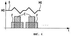
На фиг. 4 на диаграмме схематично показано, в какие моменты времени происходит впрыскивание E, в какие моменты времени происходит нагнетание F топлива первой плунжерной парой и каким образом на это реагирует изображенное кривой D давление в высоконапорном аккумуляторе 6. На этой диаграмме видно, что с началом нагнетания топлива, продолжающимся в целом дольше соответствующей длительности впрыскивания и начинающимся раньше момента начала впрыскивания, давление сначала нарастает, а затем с началом впрыскивания падает и по окончании впрыскивания за счет продолжающейся подачи насосом топлива под высоким давлением снова может подняться до первоначального уровня. Иными словами, если количество подаваемого под высоким давлением топлива F согласуется с количеством впрыскиваемого топлива, в целом давление устанавливается на среднем уровне MD. В этом режиме вторая плунжерная пара 17 хотя и приводится в действие, однако нагнетание топлива под высоким давлением в высоконапорный аккумулятор из-за открытого электромагнитного клапана 4 не происходит. Подаваемое плунжером 20 топливо через открытый электромагнитный клапан поступает обратно в топливный бак 2. In FIG. 4, the diagram schematically shows at what points in time E is injected, at what points in time fuel F is injected by the first plunger pair and how the pressure in the high-
Если же по каким-либо причинам, обусловленными условиями работы ДВС, в высоконапорном аккумуляторе требуется установить более высокое давление впрыскивания, то для подачи топлива задействуется вторая плунжерная пара. В этом случае электромагнитный клапан 4 второй плунжерной пары 17 полностью закрывается, и поэтому плунжер 20 этой плунжерной пары за каждый ход нагнетания подает под высоким давлением в высоконапорный аккумулятор одинаковое количество топлива, т.е. работает с постоянной цикловой подачей. Точное регулирование давления в топливном высоконапорном аккумуляторе осуществляется в этом случае путем соответствующего управления электромагнитным клапаном 4 первой плунжерной пары. При этом подача топлива может производиться и синхронно с его подачей первой плунжерной парой, однако предпочтительно подавать это постоянное количество топлива в те интервалы времени, когда впрыскивания не происходит. На фиг. 5 видно, что указанная подача топлива под высоким давлением FK осуществляется в промежутке времени между отдельными циклами подачи F первой плунжерной пары, а следовательно, и между отдельными циклами впрыскивания топлива клапанными форсунками. На кривой графика давления видно, что с началом подачи FK давление с первого уровня D1 поднимается до второго уровня D2. Во время впрыскивания этот уровень давления сохраняется за счет нагнетания топлива первой плунжерной парой. При этом изображенный на фиг. 5 участок кривой, соответствующий спаду давления при расходовании топлива в процессе впрыскивания, на фиг. 4 опущен. If for some reason due to the operating conditions of the internal combustion engine, a higher injection pressure is required to be set in the high-pressure accumulator, then a second plunger pair is used to supply fuel. In this case, the
В отличие от варианта осуществления управления второй плунжерной парой по фиг. 2 в варианте по фиг. 3 управление второй плунжерной парой 17' может осуществляться с помощью регулирующего клапана 4', выполненного в данном случае также в виде электромагнитного клапана, но размещенного не в отдельном разгрузочном топливопроводе, а в подводящем трубопроводе, соединяющем топливоподающий насос 24 с надплунжерным пространством 23, соответственно с наполнительным отверстием 25. Предусматривавшийся ранее разгрузочный топливопровод в данном варианте можно исключить. При этом для дополнительной подачи топлива под высоким давлением второй плунжерной парой 17' открывается регулирующий клапан 4', обеспечивая возможность полного заполнения топливом надплунжерного пространства 23. Для отключения второй плунжерной пары регулирующий клапан 4' закрывается. Для подачи топлива под высоким давлением и в этом варианте используется постоянный ход плунжерной пары 17' при ее подключении. Вместо этого или же дополнительно к этому для управляемого подсоединения отверстия 28 к наполнительному отверстию 25 через распределительный паз 29 можно также предусмотреть обеспечиваемое с помощью соответствующего обратного клапана 30 соединение с надплунжерным пространством 23 в фазе впуска. В этом случае изображенное на фиг. 2 отверстие 28, высотой расположения которого определяется момент окончания нагнетания, становится излишним. In contrast to the embodiment for controlling the second plunger pair of FIG. 2 in the embodiment of FIG. 3, the control of the second plunger pair 17 'can be carried out using a control valve 4', made in this case also in the form of an electromagnetic valve, but not located in a separate discharge fuel pipe, but in a supply pipe connecting the
Благодаря такой конструкции становится возможным быстро повысить давление в высоконапорном аккумуляторе, что прежде всего необходимо для работы ДВС в определенных режимах, таких, как ускорение или увеличение количества впрыскиваемого топлива. Осуществляется это очень простым образом с минимальными затратами на электронные средства управления и с использованием быстро и точно переключающихся клапанов. Электромагнитный клапан 4' второй плунжерной пары в отличие от электромагнитного клапана 4 первой плунжерной пары может иметь очень простую конструкцию, поскольку он не должен выполнять никаких функций по временной синхронизации. Соответственно ниже оказываются и затраты при таком решении. Благодаря промежуточной подаче топлива FK можно очень быстро реагировать на требуемые изменения уровня давления в высоконапорном аккумуляторе, вследствие чего регулирование осуществляется точно и быстро. Очевидно, что вместо описанного выше количества плунжерных пар можно использовать и несколько плунжерных пар с регулируемой цикловой подачей и несколько плунжерных пар с постоянной цикловой подачей. Thanks to this design, it becomes possible to quickly increase the pressure in the high-pressure accumulator, which is primarily necessary for the operation of the internal combustion engine in certain modes, such as accelerating or increasing the amount of injected fuel. This is done in a very simple way with minimal cost of electronic controls and using quickly and accurately switching valves. The electromagnetic valve 4 'of the second plunger pair, unlike the
Claims (7)
Applications Claiming Priority (2)
| Application Number | Priority Date | Filing Date | Title |
|---|---|---|---|
| DE19646581.8 | 1996-11-12 | ||
| DE19646581A DE19646581A1 (en) | 1996-11-12 | 1996-11-12 | Fuel injection system |
Publications (2)
| Publication Number | Publication Date |
|---|---|
| RU98114976A RU98114976A (en) | 2000-05-10 |
| RU2177077C2 true RU2177077C2 (en) | 2001-12-20 |
Family
ID=7811337
Family Applications (1)
| Application Number | Title | Priority Date | Filing Date |
|---|---|---|---|
| RU98114976/06A RU2177077C2 (en) | 1996-11-12 | 1997-06-30 | Fuel injection system |
Country Status (9)
| Country | Link |
|---|---|
| US (1) | US6095118A (en) |
| EP (1) | EP0873473B1 (en) |
| JP (1) | JP3889057B2 (en) |
| KR (1) | KR100482907B1 (en) |
| CN (1) | CN1076789C (en) |
| DE (2) | DE19646581A1 (en) |
| ES (1) | ES2174267T3 (en) |
| RU (1) | RU2177077C2 (en) |
| WO (1) | WO1998021470A1 (en) |
Cited By (3)
| Publication number | Priority date | Publication date | Assignee | Title |
|---|---|---|---|---|
| US7913667B2 (en) | 2005-03-02 | 2011-03-29 | Toyota Jidosha Kabushiki Kaisha | Fuel supply apparatus for vehicle |
| RU2468241C2 (en) * | 2007-07-24 | 2012-11-27 | Роберт Бош Гмбх | Internal combustion engine with several cylinders |
| RU2501968C2 (en) * | 2008-08-20 | 2013-12-20 | Роберт Бош Гмбх | Device to supply fuel to internal combustion engine |
Families Citing this family (42)
| Publication number | Priority date | Publication date | Assignee | Title |
|---|---|---|---|---|
| BR0008300B1 (en) * | 1999-02-17 | 2011-08-23 | gasoline fuel injection system for an internal combustion engine, and methods for controlling the operation of a common high pressure feeder direct gasoline injection system for an internal combustion engine, and for controlling a fuel injection system gasoline fuel from common feeder. | |
| DE19948464A1 (en) * | 1999-10-08 | 2001-04-12 | Bosch Gmbh Robert | Common rail fuel injection system |
| US6866025B1 (en) * | 1999-11-18 | 2005-03-15 | Siemens Vdo Automotive Corp. | High pressure fuel pump delivery control by piston deactivation |
| DE50013384D1 (en) * | 1999-11-19 | 2006-10-12 | Crt Common Rail Tech Ag | High-pressure injection system with common rail |
| JP2001207927A (en) * | 2000-01-26 | 2001-08-03 | Mitsubishi Electric Corp | Fuel supply device |
| JP2001263198A (en) * | 2000-03-14 | 2001-09-26 | Bosch Automotive Systems Corp | Fuel pump and fuel supply device using it |
| DE10023033A1 (en) * | 2000-05-11 | 2001-11-22 | Bosch Gmbh Robert | Operation of fuel metering system of direct injection engine, places all high pressure pumps in fuel circuit, with common pressure control system |
| DE10052629A1 (en) * | 2000-10-24 | 2002-05-08 | Bosch Gmbh Robert | High pressure fuel pump with variable delivery rate |
| DE10057683B4 (en) * | 2000-11-21 | 2005-10-06 | Robert Bosch Gmbh | Fuel injection system |
| JP4123729B2 (en) * | 2001-03-15 | 2008-07-23 | 株式会社日立製作所 | Control method of fuel supply device |
| US6899083B2 (en) * | 2001-09-10 | 2005-05-31 | Stanadyne Corporation | Hybrid demand control for hydraulic pump |
| DE10153189A1 (en) * | 2001-10-27 | 2003-05-15 | Bosch Gmbh Robert | Fuel pump, fuel system, method for operating a fuel system and internal combustion engine |
| KR20030048172A (en) * | 2001-12-11 | 2003-06-19 | 현대자동차주식회사 | Cylinder deactivation device using cam |
| GB2383295A (en) * | 2001-12-19 | 2003-06-25 | Michael Ghahari | Repairable solid surface laminate |
| DE10215021A1 (en) * | 2002-04-05 | 2003-10-23 | Bosch Gmbh Robert | Fuel injection device for an internal combustion engine |
| US7201147B2 (en) * | 2002-08-13 | 2007-04-10 | International Engine Intellectual Property Company, Llc | Control strategies for a variable displacement oil pump |
| JP4123952B2 (en) * | 2003-02-06 | 2008-07-23 | トヨタ自動車株式会社 | Fuel supply system for internal combustion engine |
| DE10315318A1 (en) * | 2003-04-04 | 2004-10-14 | Robert Bosch Gmbh | Method for operating an internal combustion engine |
| US6973921B2 (en) * | 2003-12-12 | 2005-12-13 | Caterpillar Inc. | Fuel pumping system and method |
| JP4148145B2 (en) * | 2004-01-22 | 2008-09-10 | 株式会社デンソー | Fuel supply device for internal combustion engine |
| ITBO20040323A1 (en) * | 2004-05-20 | 2004-08-20 | Magneti Marelli Powertrain Spa | METHOD OF DIRECT INJECTION OF FUEL INTO AN INTERNAL COMBUSTION ENGINE |
| ITBO20040322A1 (en) * | 2004-05-20 | 2004-08-20 | Magneti Marelli Powertrain Spa | METHOD AND SYSTEM FOR DIRECT FUEL INJECTION INTO AN INTERNAL COMBUSTION ENGINE |
| ATE507384T1 (en) * | 2004-06-30 | 2011-05-15 | Fiat Ricerche | FUEL INJECTION SYSTEM FOR INTERNAL COMBUSTION ENGINE WITH COMMON RAIL |
| KR100795406B1 (en) * | 2004-07-12 | 2008-01-17 | 얀마 가부시키가이샤 | Accumulator fuel injection device and internal combustion engine with the accumulator fuel injection device |
| JP2006046169A (en) * | 2004-08-04 | 2006-02-16 | Toyota Motor Corp | Fuel pressure control device for internal combustion engine |
| US7398763B2 (en) | 2005-11-09 | 2008-07-15 | Caterpillar Inc. | Multi-source fuel system for variable pressure injection |
| JP4506700B2 (en) * | 2006-03-27 | 2010-07-21 | 株式会社デンソー | Fuel injection control device |
| US7353800B2 (en) * | 2006-05-24 | 2008-04-08 | Caterpillar Inc. | Multi-source fuel system having grouped injector pressure control |
| US7431017B2 (en) * | 2006-05-24 | 2008-10-07 | Caterpillar Inc. | Multi-source fuel system having closed loop pressure control |
| US7392791B2 (en) | 2006-05-31 | 2008-07-01 | Caterpillar Inc. | Multi-source fuel system for variable pressure injection |
| US8015964B2 (en) * | 2006-10-26 | 2011-09-13 | David Norman Eddy | Selective displacement control of multi-plunger fuel pump |
| GB0622564D0 (en) * | 2006-11-13 | 2006-12-20 | Airbus Uk Ltd | Water scavenging system |
| US20080115770A1 (en) * | 2006-11-16 | 2008-05-22 | Merchant Jack A | Pump with torque reversal avoidance feature and engine system using same |
| FR2914959B1 (en) * | 2007-04-13 | 2013-03-08 | Siemens Automotive Hydraulics Sa | IMPROVEMENT TO HIGH-PRESSURE FUEL SUPPLY DEVICES BY TRANSFER PUMP |
| EP2063093A1 (en) * | 2007-11-26 | 2009-05-27 | Delphi Technologies, Inc. | Fuel injection system |
| EP2085603A1 (en) * | 2008-01-31 | 2009-08-05 | Caterpillar Motoren GmbH & Co. KG | System and method of prevention CR pump overheating |
| DE102008001019A1 (en) * | 2008-04-07 | 2009-10-08 | Robert Bosch Gmbh | High pressure pump arrangement with one-time high-pressure pump |
| US8834134B2 (en) | 2010-12-20 | 2014-09-16 | Woodward, Inc. | Flow sensing dual pump switching system and method |
| JP5799919B2 (en) | 2012-09-06 | 2015-10-28 | 株式会社デンソー | Pump control device |
| US9422898B2 (en) * | 2013-02-12 | 2016-08-23 | Ford Global Technologies, Llc | Direct injection fuel pump |
| US10260444B2 (en) * | 2013-12-19 | 2019-04-16 | Fca Us Llc | Direct injection fuel system with controlled accumulator energy storage |
| DE102015209377B4 (en) * | 2015-05-21 | 2017-05-11 | Mtu Friedrichshafen Gmbh | Injection system for an internal combustion engine and internal combustion engine with such an injection system |
Family Cites Families (6)
| Publication number | Priority date | Publication date | Assignee | Title |
|---|---|---|---|---|
| JPH07122422B2 (en) * | 1986-05-02 | 1995-12-25 | 日本電装株式会社 | Fuel injector |
| US5197438A (en) * | 1987-09-16 | 1993-03-30 | Nippondenso Co., Ltd. | Variable discharge high pressure pump |
| US5058553A (en) * | 1988-11-24 | 1991-10-22 | Nippondenso Co., Ltd. | Variable-discharge high pressure pump |
| JP2861429B2 (en) * | 1991-02-27 | 1999-02-24 | 株式会社デンソー | Accumulation type fuel injection system for diesel engine |
| JP3033214B2 (en) * | 1991-02-27 | 2000-04-17 | 株式会社デンソー | Accumulation type fuel supply method and apparatus by a plurality of fuel pumping means, and abnormality determination apparatus in equipment having a plurality of fluid pumping means |
| DE69200427T2 (en) * | 1991-04-04 | 1995-02-16 | Toyota Motor Co Ltd | Fuel injection device of an internal combustion engine. |
-
1996
- 1996-11-12 DE DE19646581A patent/DE19646581A1/en not_active Withdrawn
-
1997
- 1997-06-30 US US09/101,620 patent/US6095118A/en not_active Expired - Lifetime
- 1997-06-30 CN CN97191632A patent/CN1076789C/en not_active Expired - Fee Related
- 1997-06-30 ES ES97932714T patent/ES2174267T3/en not_active Expired - Lifetime
- 1997-06-30 EP EP97932714A patent/EP0873473B1/en not_active Expired - Lifetime
- 1997-06-30 WO PCT/DE1997/001370 patent/WO1998021470A1/en active IP Right Grant
- 1997-06-30 RU RU98114976/06A patent/RU2177077C2/en not_active IP Right Cessation
- 1997-06-30 DE DE59706681T patent/DE59706681D1/en not_active Expired - Lifetime
- 1997-06-30 JP JP52200398A patent/JP3889057B2/en not_active Expired - Fee Related
- 1997-06-30 KR KR10-1998-0705097A patent/KR100482907B1/en not_active IP Right Cessation
Cited By (3)
| Publication number | Priority date | Publication date | Assignee | Title |
|---|---|---|---|---|
| US7913667B2 (en) | 2005-03-02 | 2011-03-29 | Toyota Jidosha Kabushiki Kaisha | Fuel supply apparatus for vehicle |
| RU2468241C2 (en) * | 2007-07-24 | 2012-11-27 | Роберт Бош Гмбх | Internal combustion engine with several cylinders |
| RU2501968C2 (en) * | 2008-08-20 | 2013-12-20 | Роберт Бош Гмбх | Device to supply fuel to internal combustion engine |
Also Published As
| Publication number | Publication date |
|---|---|
| DE59706681D1 (en) | 2002-04-25 |
| DE19646581A1 (en) | 1998-05-14 |
| EP0873473A1 (en) | 1998-10-28 |
| EP0873473B1 (en) | 2002-03-20 |
| KR100482907B1 (en) | 2005-07-21 |
| CN1207160A (en) | 1999-02-03 |
| JP2000505177A (en) | 2000-04-25 |
| ES2174267T3 (en) | 2002-11-01 |
| JP3889057B2 (en) | 2007-03-07 |
| CN1076789C (en) | 2001-12-26 |
| KR19990076969A (en) | 1999-10-25 |
| WO1998021470A1 (en) | 1998-05-22 |
| US6095118A (en) | 2000-08-01 |
Similar Documents
| Publication | Publication Date | Title |
|---|---|---|
| RU2177077C2 (en) | Fuel injection system | |
| EP2010780B1 (en) | Fuel supply system for an internal combustion engine | |
| JP2651432B2 (en) | Common rail fuel injector | |
| USRE33270E (en) | Pressure-controlled fuel injection for internal combustion engines | |
| US7261087B2 (en) | High-pressure variable-flow-rate pump for a fuel-injection system | |
| US5261366A (en) | Method of fuel injection rate control | |
| US4628881A (en) | Pressure-controlled fuel injection for internal combustion engines | |
| JPH09287536A (en) | Fuel injection device | |
| EP1241338A2 (en) | Fuel supply system | |
| RU98114976A (en) | FUEL INJECTION SYSTEM | |
| JP4624846B2 (en) | Volumetric fuel injection system for internal combustion engines | |
| JP2000161115A (en) | Fuel pump control device for internal combustion engine | |
| EP0685644B1 (en) | High pressure pump for fuel injection systems | |
| EP1612394A1 (en) | Fuel injection system for an internal combustion engine with common rail | |
| EP1761688B1 (en) | Method and apparatus for lubricating cylinder surfaces in large diesel engines | |
| US7263979B2 (en) | High-pressure pump with a device for regulating the flow rate for a fuel-injection system | |
| EP1865193A1 (en) | Fuel injection system for an internal combustion engine | |
| JP2639017B2 (en) | Variable discharge high pressure pump and control method thereof | |
| JP3360336B2 (en) | Fuel injection device for internal combustion engine | |
| US6305358B1 (en) | Method and apparatus for dynamic trimming of fuel system | |
| EP0962650B1 (en) | Accumulator-type fuel injection apparatus and control method for the same | |
| US20140338637A1 (en) | Common rail system having mechanical unit pumps | |
| CA1170903A (en) | Single solenoid floating piston distributor pump | |
| CN213039381U (en) | Electronic control fuel injection system of engine | |
| JP3557871B2 (en) | Fuel injection device |
Legal Events
| Date | Code | Title | Description |
|---|---|---|---|
| MM4A | The patent is invalid due to non-payment of fees |
Effective date: 20130701 |