EP1865193A1 - Fuel injection system for an internal combustion engine - Google Patents
Fuel injection system for an internal combustion engine Download PDFInfo
- Publication number
- EP1865193A1 EP1865193A1 EP06425394A EP06425394A EP1865193A1 EP 1865193 A1 EP1865193 A1 EP 1865193A1 EP 06425394 A EP06425394 A EP 06425394A EP 06425394 A EP06425394 A EP 06425394A EP 1865193 A1 EP1865193 A1 EP 1865193A1
- Authority
- EP
- European Patent Office
- Prior art keywords
- injection system
- solenoid valve
- fuel
- pump
- holes
- Prior art date
- Legal status (The legal status is an assumption and is not a legal conclusion. Google has not performed a legal analysis and makes no representation as to the accuracy of the status listed.)
- Granted
Links
- 239000000446 fuel Substances 0.000 title claims abstract description 58
- 238000002347 injection Methods 0.000 title claims abstract description 37
- 239000007924 injection Substances 0.000 title claims abstract description 37
- 238000002485 combustion reaction Methods 0.000 title claims description 7
- 238000005086 pumping Methods 0.000 claims abstract description 42
- 238000009825 accumulation Methods 0.000 claims abstract description 29
- 239000006199 nebulizer Substances 0.000 claims abstract description 18
- 238000004891 communication Methods 0.000 claims abstract description 9
- 230000000875 corresponding effect Effects 0.000 claims description 30
- 238000012384 transportation and delivery Methods 0.000 claims description 9
- 230000002596 correlated effect Effects 0.000 claims description 2
- 238000010586 diagram Methods 0.000 description 5
- 230000006835 compression Effects 0.000 description 4
- 238000007906 compression Methods 0.000 description 4
- 230000001105 regulatory effect Effects 0.000 description 3
- 238000001816 cooling Methods 0.000 description 2
- 239000002828 fuel tank Substances 0.000 description 2
- 230000005540 biological transmission Effects 0.000 description 1
- 230000001276 controlling effect Effects 0.000 description 1
- 238000007599 discharging Methods 0.000 description 1
- 239000003502 gasoline Substances 0.000 description 1
- 230000001050 lubricating effect Effects 0.000 description 1
- 238000005461 lubrication Methods 0.000 description 1
- 230000009347 mechanical transmission Effects 0.000 description 1
- 230000007246 mechanism Effects 0.000 description 1
- 238000012986 modification Methods 0.000 description 1
- 230000004048 modification Effects 0.000 description 1
- 238000011144 upstream manufacturing Methods 0.000 description 1
Images

Classifications
-
- F—MECHANICAL ENGINEERING; LIGHTING; HEATING; WEAPONS; BLASTING
- F02—COMBUSTION ENGINES; HOT-GAS OR COMBUSTION-PRODUCT ENGINE PLANTS
- F02M—SUPPLYING COMBUSTION ENGINES IN GENERAL WITH COMBUSTIBLE MIXTURES OR CONSTITUENTS THEREOF
- F02M55/00—Fuel-injection apparatus characterised by their fuel conduits or their venting means; Arrangements of conduits between fuel tank and pump F02M37/00
- F02M55/02—Conduits between injection pumps and injectors, e.g. conduits between pump and common-rail or conduits between common-rail and injectors
-
- F—MECHANICAL ENGINEERING; LIGHTING; HEATING; WEAPONS; BLASTING
- F02—COMBUSTION ENGINES; HOT-GAS OR COMBUSTION-PRODUCT ENGINE PLANTS
- F02M—SUPPLYING COMBUSTION ENGINES IN GENERAL WITH COMBUSTIBLE MIXTURES OR CONSTITUENTS THEREOF
- F02M59/00—Pumps specially adapted for fuel-injection and not provided for in groups F02M39/00 -F02M57/00, e.g. rotary cylinder-block type of pumps
- F02M59/44—Details, components parts, or accessories not provided for in, or of interest apart from, the apparatus of groups F02M59/02 - F02M59/42; Pumps having transducers, e.g. to measure displacement of pump rack or piston
- F02M59/46—Valves
- F02M59/466—Electrically operated valves, e.g. using electromagnetic or piezoelectric operating means
-
- F—MECHANICAL ENGINEERING; LIGHTING; HEATING; WEAPONS; BLASTING
- F02—COMBUSTION ENGINES; HOT-GAS OR COMBUSTION-PRODUCT ENGINE PLANTS
- F02M—SUPPLYING COMBUSTION ENGINES IN GENERAL WITH COMBUSTIBLE MIXTURES OR CONSTITUENTS THEREOF
- F02M59/00—Pumps specially adapted for fuel-injection and not provided for in groups F02M39/00 -F02M57/00, e.g. rotary cylinder-block type of pumps
- F02M59/02—Pumps specially adapted for fuel-injection and not provided for in groups F02M39/00 -F02M57/00, e.g. rotary cylinder-block type of pumps of reciprocating-piston or reciprocating-cylinder type
- F02M59/10—Pumps specially adapted for fuel-injection and not provided for in groups F02M39/00 -F02M57/00, e.g. rotary cylinder-block type of pumps of reciprocating-piston or reciprocating-cylinder type characterised by the piston-drive
-
- F—MECHANICAL ENGINEERING; LIGHTING; HEATING; WEAPONS; BLASTING
- F02—COMBUSTION ENGINES; HOT-GAS OR COMBUSTION-PRODUCT ENGINE PLANTS
- F02M—SUPPLYING COMBUSTION ENGINES IN GENERAL WITH COMBUSTIBLE MIXTURES OR CONSTITUENTS THEREOF
- F02M59/00—Pumps specially adapted for fuel-injection and not provided for in groups F02M39/00 -F02M57/00, e.g. rotary cylinder-block type of pumps
- F02M59/20—Varying fuel delivery in quantity or timing
- F02M59/205—Quantity of fuel admitted to pumping elements being metered by an auxiliary metering device
-
- F—MECHANICAL ENGINEERING; LIGHTING; HEATING; WEAPONS; BLASTING
- F02—COMBUSTION ENGINES; HOT-GAS OR COMBUSTION-PRODUCT ENGINE PLANTS
- F02M—SUPPLYING COMBUSTION ENGINES IN GENERAL WITH COMBUSTIBLE MIXTURES OR CONSTITUENTS THEREOF
- F02M59/00—Pumps specially adapted for fuel-injection and not provided for in groups F02M39/00 -F02M57/00, e.g. rotary cylinder-block type of pumps
- F02M59/20—Varying fuel delivery in quantity or timing
- F02M59/36—Varying fuel delivery in quantity or timing by variably-timed valves controlling fuel passages to pumping elements or overflow passages
- F02M59/366—Valves being actuated electrically
-
- F—MECHANICAL ENGINEERING; LIGHTING; HEATING; WEAPONS; BLASTING
- F02—COMBUSTION ENGINES; HOT-GAS OR COMBUSTION-PRODUCT ENGINE PLANTS
- F02M—SUPPLYING COMBUSTION ENGINES IN GENERAL WITH COMBUSTIBLE MIXTURES OR CONSTITUENTS THEREOF
- F02M59/00—Pumps specially adapted for fuel-injection and not provided for in groups F02M39/00 -F02M57/00, e.g. rotary cylinder-block type of pumps
- F02M59/44—Details, components parts, or accessories not provided for in, or of interest apart from, the apparatus of groups F02M59/02 - F02M59/42; Pumps having transducers, e.g. to measure displacement of pump rack or piston
-
- F—MECHANICAL ENGINEERING; LIGHTING; HEATING; WEAPONS; BLASTING
- F02—COMBUSTION ENGINES; HOT-GAS OR COMBUSTION-PRODUCT ENGINE PLANTS
- F02M—SUPPLYING COMBUSTION ENGINES IN GENERAL WITH COMBUSTIBLE MIXTURES OR CONSTITUENTS THEREOF
- F02M2200/00—Details of fuel-injection apparatus, not otherwise provided for
- F02M2200/16—Sealing of fuel injection apparatus not otherwise provided for
-
- F—MECHANICAL ENGINEERING; LIGHTING; HEATING; WEAPONS; BLASTING
- F02—COMBUSTION ENGINES; HOT-GAS OR COMBUSTION-PRODUCT ENGINE PLANTS
- F02M—SUPPLYING COMBUSTION ENGINES IN GENERAL WITH COMBUSTIBLE MIXTURES OR CONSTITUENTS THEREOF
- F02M59/00—Pumps specially adapted for fuel-injection and not provided for in groups F02M39/00 -F02M57/00, e.g. rotary cylinder-block type of pumps
- F02M59/02—Pumps specially adapted for fuel-injection and not provided for in groups F02M39/00 -F02M57/00, e.g. rotary cylinder-block type of pumps of reciprocating-piston or reciprocating-cylinder type
- F02M59/08—Pumps specially adapted for fuel-injection and not provided for in groups F02M39/00 -F02M57/00, e.g. rotary cylinder-block type of pumps of reciprocating-piston or reciprocating-cylinder type characterised by two or more pumping elements with conjoint outlet or several pumping elements feeding one engine cylinder
Definitions
- the present invention relates to a fuel-injection system for an internal-combustion engine.
- the high-pressure pump of the injection system is designed to send fuel to a common rail for the fuel under pressure to supply a plurality of injectors associated to the cylinders of the engine.
- the pressure of the fuel required in the accumulation volume for this type of systems is in general defined by an electronic control unit as a function of the operating conditions of the engine.
- Injection systems are known in which a by-pass solenoid valve, set on the delivery pipe of the pump, is controlled by the control unit for discharging the fuel pumped in excess directly into the usual fuel tank before it enters the common rail, dissipating in the form of heat a part of the compression energy of the high-pressure pump.
- the intake pipe of the pump is provided with a device for regulating the flowrate, comprising a restriction with step less varying cross section, controlled by the electronic control unit as a function of the pressure required in the common rail and/or of the operating condition of the engine.
- the device for regulating the flowrate is supplied with a constant pressure of approximately 5 bar, supplied by an auxiliary pump.
- the pressure of the fuel in the volume downstream of the regulating solenoid valve and upstream of the intake valves is relatively low and consequently contributes only to a small extent to the force for opening the intake valves themselves.
- the usual return spring of the intake valve must thus be such as to guarantee opening thereof even with a minimum pressure close to zero in said volume.
- said spring must be calibrated in a very precise way, so that the pump is relatively costly.
- there is always the risk that the negative pressure caused by the pumping element in the compression chamber is not sufficient to bring about opening of the intake valve, so that the pump does not operate properly and is subject to deteriorate easily. In either case, if the pump has a number of pumping elements, it always gives rise to asymmetrical deliveries, which generate mutual perturbations, known as "cross talk".
- the aim of the invention is to provide a fuel-injection system, comprising a high-pressure pump having a variable flowrate, such that it will present a high degree of reliability and a limited cost, eliminating the drawbacks of the fuel-injection systems of the known art.
- a fuel-injection system for an internal-combustion engine comprising a high-pressure pump having a variable flowrate, as defined in Claim 1.
- an accumulation volume for fuel at low pressure has outlet holes in communication with the intake valves of the pumping elements, this accumulation volume being supplied through a solenoid valve designed to generate jets of fuel directed towards at least one corresponding outlet hole, the solenoid valve being controlled asynchronously with respect to the intake strokes of the pumping elements as a function of the operating conditions of the engine.
- number 1 designates as a whole a fuel-injection system for an internal-combustion engine 2, for example a four-stroke diesel engine.
- the engine 2 comprises a plurality of cylinders 3, for example four cylinders, in which corresponding pistons (not shown) slide for turning a driving shaft 4.
- the injection system 1 comprises a plurality of electrically controlled injectors 5, designed to inject the high-pressure fuel into the corresponding cylinders 3.
- the injectors 5 are supplied by an accumulation volume for the pressurized fuel, which in the embodiment illustrated, is formed by the usual common rail 6.
- the common rail 6 is supplied with high-pressure fuel by a high-pressure pump, designated as a whole by 7, via a delivery pipe 8.
- the high-pressure pump 7 is supplied by a low-pressure pump, for example an electric pump 9, via an intake pipe 10 of the pump 7.
- the electric pump 9 is in general set in the usual fuel tank 11, into which there gives out a pipe 12 for discharge of the fuel in excess of the injection system 1.
- a part of the fuel of the pipe 10 is sent, via a pressure regulator 15, to a crankcase 17 of the pump 7, for cooling and lubricating the mechanisms thereof, in a way in itself known.
- the common rail 6 is moreover provided with a discharge solenoid valve 13 in communication with the discharge pipe 12.
- Each injector 5 is designed to inject, into the corresponding cylinder 3, a quantity of fuel that varies between a minimum value and a maximum value under the control of an electronic control unit 14, which can be formed by the usual microprocessor electronic control unit (ECU) for controlling the engine 2.
- the control unit 14 is designed to receive signals indicating the operating conditions of the engine 2, such as the position of the accelerator pedal and the r.p.m. of the driving shaft 4, which are generated by corresponding sensors (not shown), as well as the pressure of the fuel in the common rail 6, detected by a pressure sensor 16.
- the control unit 14 by processing the received signals, by means of a purposely provided program controls the instant and duration of the actuation of the individual injectors 5, as well as opening and closing of the discharge solenoid valve 13. Consequently, the discharge pipe 12 conveys into the tank 11 both the discharge fuel of the injectors 5 and the possible fuel in excess in the common rail 6, discharged by the solenoid valve 13, as well as the fuel for cooling and lubrication coming from the crankcase 17 of the pump 7.
- the high-pressure pump 7 of Figure 1 comprises a pair of pumping elements 18 and 18a, each formed by a cylinder 19 having a compression chamber 20, in which a piston 21 slides with a reciprocating motion comprising an intake stroke and a delivery stroke.
- Each pumping element 18, 18a is provided with a corresponding intake valve 22, 22a and a corresponding delivery valve 23, 23a.
- the valves 22, 22a and 23, 23a can be of the ball type and can be provided with respective return springs 24.
- the two intake valves 22, 22a are in communication with the intake pipe 10 that is common to both of them, as will be more clearly seen hereinafter, whilst the two delivery valves 23, 23a are in communication with the delivery pipe 8 that said valves 23, 23a have in common.
- the two pistons 21 are actuated by corresponding eccentric cams 26 carried by an operating shaft 27 of the pump 7.
- the two pumping elements 18, 18a are in line; i.e., they are arranged alongside one another and are actuated by two eccentric cams 26 fitted on the shaft 27 with a phase difference of 180°.
- an accumulation volume 28 for the fuel to be taken in which is provided with two outlet holes 29 and 29a ( Figures 3 and 4), respectively in communication with the corresponding intake valves 22 and 22a.
- the accumulation volume 28 is supplied with the fuel at low pressure of the intake pipe 10, through a solenoid valve 31.
- the latter is designed to generate a set of jets of fuel, each directed towards at least one of the outlet holes 29, 29a of the accumulation volume 28.
- the solenoid valve 31 generates two jets, each directed towards a corresponding outlet hole 29, 29a of the accumulation volume 28.
- the solenoid valve 31 is of the on-off type and can be formed by an electromagnetically controlled low-pressure fuel injector (Figure 4), for example a gasoline injector for Otto-cycle engines.
- the injector 31 comprises a nozzle 33, terminating with a conical portion 34, in which two diametrally opposed nebulizer holes 36, 36a are provided.
- the holes 36, 36a are normally closed by a common open/close element, in the form of a needle 37 having a conical tip 38 designed to engage the internal surface of the conical portion of the nozzle 33.
- the needle 37 is axially guided by a portion 39 of the nozzle 33 and has a portion 41 having a certain play with a wall 42 of the nozzle 33 to enable passage of the fuel from an injection chamber 43.
- the needle 37 is controlled so as to open the holes 36, in a known way, by an electromagnet, not indicated in the figure.
- the accumulation volume 28 for the low-pressure fuel is constituted by a short intake pipe set downstream of the injector 31.
- the fuel is at atmospheric pressure.
- the electric pump 9 compresses the fuel to a low pressure, for example in the region of just 2-3 bar.
- the injector 31 sends the fuel to the accumulation volume 28, from which it is taken in by means of the intake valves 22, 22a of the high-pressure pump 7. This compresses the fuel received and, via the delivery pipe 8, sends the high-pressure fuel, for example in the region of 1600 bar, towards the common rail 6 for the fuel under pressure.
- the flowrate of the pump 7 is controlled exclusively by the injector 31, which is designed to be actuated in an asynchronous way with respect to the intake stroke of the pistons 21 of the pumping elements 18 and 18a.
- the injector 31, by means of the two nebulizer holes 36 and 36a ( Figures 3 and 4), generates two jets of fuel, which are directed towards the outlet holes 29 and 29a of the accumulation volume 28, and hence towards the intake valves 22 and 22a.
- the pump 7 is provided with two in line pumping elements 18 and 18a, and the accumulation volume 28 is located between the pumping elements 18 and 18a.
- the holes 36 and 36a of the injector 31, the outlet holes 29 and 29a of the accumulation volume 28 and the intake valves 22 and 22a of the pumping elements 18 and 18a are provided in positions specular to one another.
- the nebulizer holes 36 and 36a of the solenoid valve 31 and the outlet holes 29 and 29a of the accumulation volume 28 are arranged in such a way that the two jets of fuel will form an angle smaller than, or equal to, 180°(in the plane containing the axes of the holes 29, 29a and 36, 36a themselves) with respect to one another.
- the intake valves 22 and 22a and the outlet holes 29 and 29a are substantially coaxial.
- the injector 31 ( Figure 1) is controlled by the electronic control unit 14 as a function of the operating conditions of the engine 2 both during the intake stroke and during the compression stroke of the piston 21 of each pumping element 18, 18a.
- the injector 31 is controlled by the control unit 14 by means of control signals modulated in frequency and/or in duty-cycle.
- control signals modulated in frequency and/or in duty-cycle.
- Said signals can have a duration of the order of one thousandth of a second, whilst the duty-cycle can vary widely between 2% and 95%.
- control unit 14 this latter is designed to control the injector 31 by means of control signals A of constant duration t 1 , the frequency of which is modulated. Consequently, in order to vary the amount of fuel to be pumped, the time interval B between the signals A is varied.
- control unit 14 is designed to control the injector 31 by means of control signals C having a constant frequency (and hence, period), the duty-cycle of which is modulated.
- the constancy of the frequency is indicated in Figure 2 by the constancy of the distance of the dashed lines G (i.e., by the constancy of the periods).
- the nebulizer holes 36 and 36a of the injector 31 have an outlet section, i.e., a section of effective passage, which is relatively small so as to enable the fuel metering before it is brought up to a high pressure by the pump 7.
- said section of passage is such that, with the control at the maximum frequency or at the maximum duty-cycle of the control signal, the injector 31 will present a maximum instantaneous flowrate higher than the maximum instantaneous flowrate that can be taken in by each intake valve 22, 22a, said maximum flowrate being defined by the product of the maximum speed of the pumping element and the bore thereof.
- the maximum instantaneous flowrate of the injector 31 is chosen so as to be up to 20% more than the maximum instantaneous flowrate of each intake valve 22, 22a.
- the section of passage of the nebulizer holes 36, 36a of the injector 31 is also such as to create a mean flowrate, during a pre-set time interval T, which is greater than the mean flowrate of fuel taken in through each intake valve 22, 22a.
- said time interval T is indicated by two dashed-and-dotted lines and comprises a plurality of signals A and C. Said time interval can be of the same order of magnitude as the duration of the intake stroke of the piston 21 of each pumping element 18, 18a. Obviously, the number of signals A and C given in Figure 2 in the time interval T is purely indicative.
- the high-pressure pump 7 can be provided with three pumping elements 18 arranged in a star configuration and actuated by a common eccentric cam.
- the accumulation volume 28 ( Figure 5) can have a prismatic shape, a cylindrical shape, or else be shaped like a spherical cap and is set substantially coaxial with the usual axis of rotation of the eccentric cam.
- the accumulation volume 28 has three outlet holes 29, 29a, 29b, arranged at 120° with respect to one another and in communication with the intake valves 22 of the three pumping elements 18, through corresponding pipes 43, 43a, 43b, made in the usual crankcase of the pump 7.
- the injector 31 is set with the conical portion 34 inserted in the accumulation volume 28 and has three nebulizer holes 36, 36a, 36b arranged at 120° with respect to one another and set so as to direct the corresponding jets of fuel at low pressure onto the three corresponding outlet holes 29, 29a, 29b so that the three jets form an angle of 120° with respect to one another.
- the pump 7 can be formed by four pumping elements 18, and the accumulation volume 28 can have four corresponding outlet holes 29, whilst the injector 31 is designed to generate four jets of fuel directed towards said outlet holes.
- the four pumping elements 18 can be grouped into two sets, possibly arranged at an angle between one another, with respect to the shaft 27 of the pump 7. In this case, actuation of the pumping elements 18 is phased in such a way that the intake stroke of a pumping element 18 of one set alternates with that of a pumping element 18 of the other set.
- the injector 31 can then be provided only with just two nebulizer holes 36, 36a, as in Figure 4, in such a way that each jet is directed towards the two intake valves of a corresponding set of pumping elements 18.
- the fuel metering is advantageously made by the injector 31 on fuel at low pressure, instead of by the pumping elements 18. Consequently, having sized appropriately the accumulation volume 28, i.e., with a value similar to that of the minimum volume of fuel required, even in the conditions of minimum flowrate required by the engine, in the volume 28 a pressure sufficient to enable opening of the valves 22 and 22a will always be obtained.
- the injector 31 is controlled at a frequency independent of the frequency of the intake strokes of the pump 7.
Landscapes
- Engineering & Computer Science (AREA)
- Chemical & Material Sciences (AREA)
- Combustion & Propulsion (AREA)
- Mechanical Engineering (AREA)
- General Engineering & Computer Science (AREA)
- Physics & Mathematics (AREA)
- Electromagnetism (AREA)
- Fuel-Injection Apparatus (AREA)
Abstract
Description
- The present invention relates to a fuel-injection system for an internal-combustion engine.
- As is known, in modern internal-combustion engines, for example diesel engines, the high-pressure pump of the injection system is designed to send fuel to a common rail for the fuel under pressure to supply a plurality of injectors associated to the cylinders of the engine. The pressure of the fuel required in the accumulation volume for this type of systems is in general defined by an electronic control unit as a function of the operating conditions of the engine.
- Injection systems are known in which a by-pass solenoid valve, set on the delivery pipe of the pump, is controlled by the control unit for discharging the fuel pumped in excess directly into the usual fuel tank before it enters the common rail, dissipating in the form of heat a part of the compression energy of the high-pressure pump.
- There have also been proposed injection systems in which the high-pressure pump presents a variable flowrate in order to reduce the amount of fuel pumped when the engine operates at a reduced power.
- In one of these systems, the intake pipe of the pump is provided with a device for regulating the flowrate, comprising a restriction with step less varying cross section, controlled by the electronic control unit as a function of the pressure required in the common rail and/or of the operating condition of the engine. In said system, the device for regulating the flowrate is supplied with a constant pressure of approximately 5 bar, supplied by an auxiliary pump. By step less varying the effective area of passage and introducing a pressure drop, the amount taken in by the pumping elements hydraulically connected thereto is modulated.
- Unfortunately, at low flowrates, the pressure of the fuel in the volume downstream of the regulating solenoid valve and upstream of the intake valves is relatively low and consequently contributes only to a small extent to the force for opening the intake valves themselves. In this type of systems, the usual return spring of the intake valve must thus be such as to guarantee opening thereof even with a minimum pressure close to zero in said volume. On the one hand, said spring must be calibrated in a very precise way, so that the pump is relatively costly. On the other hand, there is always the risk that the negative pressure caused by the pumping element in the compression chamber is not sufficient to bring about opening of the intake valve, so that the pump does not operate properly and is subject to deteriorate easily. In either case, if the pump has a number of pumping elements, it always gives rise to asymmetrical deliveries, which generate mutual perturbations, known as "cross talk".
- In another known injection system, it has been proposed to provide, on the intake pipe of the high-pressure pump, a shutoff solenoid valve, which, by introducing a small pressure drop, enables a relatively high flowrate such as to supply the pumping element with the maximum pressure possible during a variable part of the intake stroke, the instant of end of supply of which is modulated. This known injection system needs to synchronize actuation of the solenoid valve with the position of the piston of the pumping element during the intake stroke. Also in the case of mechanical transmission of the motion between the driving shaft and the shaft for actuating the pump said synchronization is difficult, also because the intake of the fuel by the injector occurs with a phase that varies as a function of the operating condition of the engine.
- The aim of the invention is to provide a fuel-injection system, comprising a high-pressure pump having a variable flowrate, such that it will present a high degree of reliability and a limited cost, eliminating the drawbacks of the fuel-injection systems of the known art.
- According to the invention, the above aim is achieved by a fuel-injection system for an internal-combustion engine, comprising a high-pressure pump having a variable flowrate, as defined in
Claim 1. - In particular, an accumulation volume for fuel at low pressure has outlet holes in communication with the intake valves of the pumping elements, this accumulation volume being supplied through a solenoid valve designed to generate jets of fuel directed towards at least one corresponding outlet hole, the solenoid valve being controlled asynchronously with respect to the intake strokes of the pumping elements as a function of the operating conditions of the engine.
- For a better understanding of the invention, a preferred embodiment is described herein, purely by way of example and with the aid of the attached drawings, wherein:
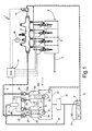
- Figure 1 is a diagram of a fuel-injection system for an internal-combustion engine, comprising a high-pressure pump having a variable flowrate, according to the invention;
- Figure 2 illustrates two diagrams of the operation of the system of Figure 1;
- Figure 3 is a partial diagram of the pump for the system of Figure 1;
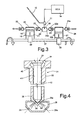
- Figure 4 is a detail of a variant of the supply of the pump, at an enlarged scale; and
- Figure 5 is a diagram of a detail of the supply of a pump with three pumping elements.
- With reference to Figure 1,
number 1 designates as a whole a fuel-injection system for an internal-combustion engine 2, for example a four-stroke diesel engine. Theengine 2 comprises a plurality ofcylinders 3, for example four cylinders, in which corresponding pistons (not shown) slide for turning a driving shaft 4. Theinjection system 1 comprises a plurality of electrically controlled injectors 5, designed to inject the high-pressure fuel into thecorresponding cylinders 3. The injectors 5 are supplied by an accumulation volume for the pressurized fuel, which in the embodiment illustrated, is formed by the usual common rail 6. - The common rail 6 is supplied with high-pressure fuel by a high-pressure pump, designated as a whole by 7, via a
delivery pipe 8. In turn, the high-pressure pump 7 is supplied by a low-pressure pump, for example anelectric pump 9, via anintake pipe 10 of thepump 7. Theelectric pump 9 is in general set in theusual fuel tank 11, into which there gives out apipe 12 for discharge of the fuel in excess of theinjection system 1. A part of the fuel of thepipe 10 is sent, via apressure regulator 15, to acrankcase 17 of thepump 7, for cooling and lubricating the mechanisms thereof, in a way in itself known. - The common rail 6 is moreover provided with a
discharge solenoid valve 13 in communication with thedischarge pipe 12. Each injector 5 is designed to inject, into thecorresponding cylinder 3, a quantity of fuel that varies between a minimum value and a maximum value under the control of anelectronic control unit 14, which can be formed by the usual microprocessor electronic control unit (ECU) for controlling theengine 2. Thecontrol unit 14 is designed to receive signals indicating the operating conditions of theengine 2, such as the position of the accelerator pedal and the r.p.m. of the driving shaft 4, which are generated by corresponding sensors (not shown), as well as the pressure of the fuel in the common rail 6, detected by apressure sensor 16. - The
control unit 14, by processing the received signals, by means of a purposely provided program controls the instant and duration of the actuation of the individual injectors 5, as well as opening and closing of thedischarge solenoid valve 13. Consequently, thedischarge pipe 12 conveys into thetank 11 both the discharge fuel of the injectors 5 and the possible fuel in excess in the common rail 6, discharged by thesolenoid valve 13, as well as the fuel for cooling and lubrication coming from thecrankcase 17 of thepump 7. - The high-
pressure pump 7 of Figure 1 comprises a pair ofpumping elements cylinder 19 having acompression chamber 20, in which apiston 21 slides with a reciprocating motion comprising an intake stroke and a delivery stroke. Eachpumping element corresponding intake valve corresponding delivery valve valves respective return springs 24. The twointake valves intake pipe 10 that is common to both of them, as will be more clearly seen hereinafter, whilst the twodelivery valves delivery pipe 8 that saidvalves pistons 21 are actuated by correspondingeccentric cams 26 carried by anoperating shaft 27 of thepump 7. In the embodiment of Figure 1, the twopumping elements eccentric cams 26 fitted on theshaft 27 with a phase difference of 180°. - According to the invention, set between the
intake pipe 10 and the twointake valves accumulation volume 28 for the fuel to be taken in, which is provided with twooutlet holes corresponding intake valves accumulation volume 28 is supplied with the fuel at low pressure of theintake pipe 10, through asolenoid valve 31. The latter is designed to generate a set of jets of fuel, each directed towards at least one of theoutlet holes accumulation volume 28. In the embodiment illustrated, thesolenoid valve 31 generates two jets, each directed towards acorresponding outlet hole accumulation volume 28. - In particular, the
solenoid valve 31 is of the on-off type and can be formed by an electromagnetically controlled low-pressure fuel injector (Figure 4), for example a gasoline injector for Otto-cycle engines. Theinjector 31 comprises anozzle 33, terminating with aconical portion 34, in which two diametrally opposednebulizer holes holes needle 37 having aconical tip 38 designed to engage the internal surface of the conical portion of thenozzle 33. Theneedle 37 is axially guided by aportion 39 of thenozzle 33 and has aportion 41 having a certain play with awall 42 of thenozzle 33 to enable passage of the fuel from aninjection chamber 43. Theneedle 37 is controlled so as to open theholes 36, in a known way, by an electromagnet, not indicated in the figure. In Figure 3, theaccumulation volume 28 for the low-pressure fuel is constituted by a short intake pipe set downstream of theinjector 31. - In the tank 11 (Figure 1), the fuel is at atmospheric pressure. In use, the
electric pump 9 compresses the fuel to a low pressure, for example in the region of just 2-3 bar. In turn, theinjector 31 sends the fuel to theaccumulation volume 28, from which it is taken in by means of theintake valves pressure pump 7. This compresses the fuel received and, via thedelivery pipe 8, sends the high-pressure fuel, for example in the region of 1600 bar, towards the common rail 6 for the fuel under pressure. - According to the invention, the flowrate of the
pump 7 is controlled exclusively by theinjector 31, which is designed to be actuated in an asynchronous way with respect to the intake stroke of thepistons 21 of thepumping elements injector 31, by means of the twonebulizer holes outlet holes accumulation volume 28, and hence towards theintake valves injector 31 is very small, it acts on thevalves intake valves pumping element corresponding piston 21. - In particular in Figures 3 and 4, the
pump 7 is provided with two inline pumping elements accumulation volume 28 is located between thepumping elements holes injector 31, theoutlet holes accumulation volume 28 and theintake valves pumping elements nebulizer holes solenoid valve 31 and theoutlet holes accumulation volume 28 are arranged in such a way that the two jets of fuel will form an angle smaller than, or equal to, 180°(in the plane containing the axes of theholes intake valves outlet holes - The injector 31 (Figure 1) is controlled by the
electronic control unit 14 as a function of the operating conditions of theengine 2 both during the intake stroke and during the compression stroke of thepiston 21 of each pumpingelement injector 31 is controlled by thecontrol unit 14 by means of control signals modulated in frequency and/or in duty-cycle. Given in Figure 2 are two diagrams that represent two types of control signals. Said signals can have a duration of the order of one thousandth of a second, whilst the duty-cycle can vary widely between 2% and 95%. - According to a first embodiment of the
control unit 14, this latter is designed to control theinjector 31 by means of control signals A of constant duration t1, the frequency of which is modulated. Consequently, in order to vary the amount of fuel to be pumped, the time interval B between the signals A is varied. According to another embodiment, thecontrol unit 14 is designed to control theinjector 31 by means of control signals C having a constant frequency (and hence, period), the duty-cycle of which is modulated. The constancy of the frequency is indicated in Figure 2 by the constancy of the distance of the dashed lines G (i.e., by the constancy of the periods). Consequently, the adjustment of the flowrate is obtained by varying the duration C of the signals and the corresponding interval D in such a way that, for any two periods G1 = C1+D1 and G2 = C2+D2, it is always G1 = G2, with C1≠C2 and D1≠D2. It is obviously possible to control theinjector 31 by modulating both the frequency of the signals and the corresponding duty-cycle. The frequency of opening of theinjector 31 is correlated to the speed of rotation of thepump 7. - The nebulizer holes 36 and 36a of the
injector 31 have an outlet section, i.e., a section of effective passage, which is relatively small so as to enable the fuel metering before it is brought up to a high pressure by thepump 7. Preferably, said section of passage is such that, with the control at the maximum frequency or at the maximum duty-cycle of the control signal, theinjector 31 will present a maximum instantaneous flowrate higher than the maximum instantaneous flowrate that can be taken in by eachintake valve injector 31 is chosen so as to be up to 20% more than the maximum instantaneous flowrate of eachintake valve - Advantageously, the section of passage of the nebulizer holes 36, 36a of the
injector 31 is also such as to create a mean flowrate, during a pre-set time interval T, which is greater than the mean flowrate of fuel taken in through eachintake valve piston 21 of each pumpingelement - From the tests carried out, it has been found that the adjustment of the flowrate of the
pump 7 enables an accurate metering of the fuel pumped upon actuation of each injector 5 via modulation of opening of theinjector 31 controlled by thecontrol unit 14. In this way, the volume of the common rail 6 of the high-pressure fuel can be enormously reduced. It has moreover been found that, if the jets of fuel are directed, through the nebulizer holes 36, 36a, towards the correspondingintake valves valves - According to a variant (not illustrated), the high-
pressure pump 7 can be provided with three pumpingelements 18 arranged in a star configuration and actuated by a common eccentric cam. In this case, the accumulation volume 28 (Figure 5) can have a prismatic shape, a cylindrical shape, or else be shaped like a spherical cap and is set substantially coaxial with the usual axis of rotation of the eccentric cam. Theaccumulation volume 28 has three outlet holes 29, 29a, 29b, arranged at 120° with respect to one another and in communication with theintake valves 22 of the threepumping elements 18, through correspondingpipes pump 7. Theinjector 31 is set with theconical portion 34 inserted in theaccumulation volume 28 and has threenebulizer holes - According to another variant of the invention, the
pump 7 can be formed by fourpumping elements 18, and theaccumulation volume 28 can have four corresponding outlet holes 29, whilst theinjector 31 is designed to generate four jets of fuel directed towards said outlet holes. The fourpumping elements 18 can be grouped into two sets, possibly arranged at an angle between one another, with respect to theshaft 27 of thepump 7. In this case, actuation of thepumping elements 18 is phased in such a way that the intake stroke of apumping element 18 of one set alternates with that of apumping element 18 of the other set. Theinjector 31 can then be provided only with just twonebulizer holes elements 18. - From what has been seen above the advantages of the injection system according to the invention with respect to the known art emerge clearly. In particular, the fuel metering is advantageously made by the
injector 31 on fuel at low pressure, instead of by thepumping elements 18. Consequently, having sized appropriately theaccumulation volume 28, i.e., with a value similar to that of the minimum volume of fuel required, even in the conditions of minimum flowrate required by the engine, in the volume 28 a pressure sufficient to enable opening of thevalves injector 31, the need for constraining actuation of theinjector 31 to the position of thepiston 21 for control of metering is eliminated. In addition, theinjector 31 is controlled at a frequency independent of the frequency of the intake strokes of thepump 7. Finally, since theinjector 31 is of the on-off type, it is simpler than the proportional solenoid valves used in known systems so that the system according to the invention presents a very contained cost. - It is understood that various modifications and improvements can be made to the injection system having the high-pressure pump and the regulation device described above without departing from the scope of the ensuing claims. For example, it is possible to eliminate the usual motion transmission device between the driving shaft 4 and the
shaft 27 of the high-pressure pump 7, which can thus be turned at a rate independent of that of the driving shaft 4. Also thesolenoid discharge valve 13 of the fuel from the common rail 6 can be eliminated.
Claims (18)
- A fuel-injection system for an internal-combustion engine, comprising a high-pressure pump (7) with variable flowrate, having a number of pumping elements (18) actuated with reciprocating motion through intake and delivery strokes, each of said pumping elements (18) being provided with a corresponding intake valve (22); said system being characterized in that a volume for accumulation (28) of fuel at low pressure is supplied by an intake pipe (10) of said pump (7) through a solenoid valve (31), said accumulation volume (28) being in communication with said intake valves (22) through corresponding outlet holes (29), said solenoid valve (31) being such as to generate corresponding jets of fuel, each directed towards at least one of said outlet holes (29).
- The injection system according to Claim 1, characterized in that each of said jets of fuel is generated by a corresponding nebulizer hole (36) of said solenoid valve (31).
- The injection system according to Claim 1 or Claim 2, characterized in that said solenoid valve (31) is constituted by an electromagnetic-control injector (32) for injection of fuel at low pressure.
- The injection system according to Claim 2 or Claim 3, in which said pump (7) is provided with a number of pumping elements (18) set in line, said system being characterized in that said solenoid valve (31) has an equal number of nebulizer holes (36) for generating said jets, each jet being directed towards the corresponding outlet hole (29) of said accumulation volume (28).
- The injection system according to Claim 4, in which said pump (7) is provided with two pumping elements (18, 18a), said system being characterized in that said solenoid valve (31) has two nebulizer holes (36), said accumulation volume (28) being set between said pumping elements (18) and having two outlet holes (29), said intake valves (22) and said outlet holes (29) being arranged in positions specular to one another.
- The injection system according to Claim 5, characterized in that the nebulizer holes (36) of said solenoid valve (36) and said outlet holes (29) are arranged in such a way that said jets form an angle smaller than 180° with respect to one another.
- The injection system according to Claim 5, characterized in that said intake valves (22) and said outlet holes (36) are substantially coaxial, said jets being directed at 180° with respect to one another.
- The injection system according to Claim 4, in which said pump (7) is provided with three pumping elements (18) arranged in a star configuration and actuated by a common eccentric cam, said system being characterized in that said accumulation volume (28) is substantially coaxial with the usual rotation axis of said eccentric cam and is in communication with the intake valves of said pumping elements through corresponding pipes.
- The injection system according to Claim 8, characterized in that the nebulizer holes (36) of said solenoid valve (31) and said outlet holes (29) are arranged in such a way that said jets form an angle smaller than 120° with respect to one another.
- The injection system according to Claim 4, in which said pump (7) is provided with four pumping elements (18), said system being characterized in that said solenoid valve (31) is provided with four nebulizer holes (36) and said accumulation volume (28) is provided with four corresponding outlet holes (29), said nebulizer holes (36) and said outlet holes (29) being arranged in such a way that said jets are directed each towards the corresponding outlet holes (29).
- The injection system according to Claim 4, in which said pump (7) is provided with four pumping elements (18) divided into two sets each formed by two pumping elements (18), said system being characterized in that, for each pumping element (18), said accumulation volume (28) is provided with a corresponding outlet hole (29), said solenoid valve (31) being provided with a nebulizer hole (36) for each of said sets of pumping elements (18), said nebulizer holes (36) being arranged so as to generate each a corresponding jet of fuel directed towards the outlet holes (29) of said accumulation volume (28) of the corresponding set of pumping elements (18).
- The injection system according to any one of the preceding claims, characterized in that said solenoid valve (31) is controlled asynchronously with respect to said intake strokes as a function of the operating conditions of the engine by a control unit (14), by means of control signals (A, C) modulated in frequency and/or in duty-cycle as a function of the operating conditions of the engine (2).
- The injection system according to Claim 12, characterized in that said control unit (14) is designed to control said solenoid valve (31) by means of control signals having a frequency correlated to the speed of rotation of said pump and/or having a variable duty-cycle.
- The injection system according to Claim 13, characterized in that said control unit (14) is designed to control said solenoid valve (31) by means of control signals (A) of constant duration, said control signals (A) being emitted with variable frequency.
- The injection system according to Claim 14, characterized in that said frequency is lower than the maximum frequency of the intake strokes of said pump (7).
- The injection system according to any one of Claims 12 to 15, characterized in that the maximum instantaneous flowrate of fuel through said solenoid valve (31) can be up to 20% more than the maximum instantaneous flowrate of fuel taken in through each of said intake valves (22).
- The injection system according to Claim 16, characterized in that the outlet section of said solenoid valve (31) is such as to deliver a flowrate higher than the mean flowrate of fuel taken in through said intake valves (22).
- The injection system according any one of Claims 12 to 17, characterized in that the duration of each control signal (A, C) is of the order of one thousandth of a second and/or said duty-cycle varies from 2% to 95%.
Priority Applications (7)
| Application Number | Priority Date | Filing Date | Title |
|---|---|---|---|
| AT06425394T ATE487055T1 (en) | 2006-06-09 | 2006-06-09 | FUEL INJECTION DEVICE FOR AN INTERNAL COMBUSTION ENGINE |
| DE602006017981T DE602006017981D1 (en) | 2006-06-09 | 2006-06-09 | Fuel injection device for an internal combustion engine |
| EP06425394A EP1865193B1 (en) | 2006-06-09 | 2006-06-09 | Fuel injection system for an internal combustion engine |
| JP2006348300A JP4536710B2 (en) | 2006-06-09 | 2006-12-25 | Fuel injection system for an internal combustion engine |
| US11/617,629 US7395812B2 (en) | 2006-06-09 | 2006-12-28 | Fuel-injection system for an internal-combustion engine |
| KR1020060138171A KR100897135B1 (en) | 2006-06-09 | 2006-12-29 | Fuel-injection system for an internal-combustion engine |
| CN2006101732322A CN101086242B (en) | 2006-06-09 | 2006-12-30 | Fuel-injection system for an internal -combustion engine |
Applications Claiming Priority (1)
| Application Number | Priority Date | Filing Date | Title |
|---|---|---|---|
| EP06425394A EP1865193B1 (en) | 2006-06-09 | 2006-06-09 | Fuel injection system for an internal combustion engine |
Publications (2)
| Publication Number | Publication Date |
|---|---|
| EP1865193A1 true EP1865193A1 (en) | 2007-12-12 |
| EP1865193B1 EP1865193B1 (en) | 2010-11-03 |
Family
ID=37198747
Family Applications (1)
| Application Number | Title | Priority Date | Filing Date |
|---|---|---|---|
| EP06425394A Active EP1865193B1 (en) | 2006-06-09 | 2006-06-09 | Fuel injection system for an internal combustion engine |
Country Status (7)
| Country | Link |
|---|---|
| US (1) | US7395812B2 (en) |
| EP (1) | EP1865193B1 (en) |
| JP (1) | JP4536710B2 (en) |
| KR (1) | KR100897135B1 (en) |
| CN (1) | CN101086242B (en) |
| AT (1) | ATE487055T1 (en) |
| DE (1) | DE602006017981D1 (en) |
Cited By (2)
| Publication number | Priority date | Publication date | Assignee | Title |
|---|---|---|---|---|
| EP2172642A1 (en) * | 2008-10-02 | 2010-04-07 | Motorenfabrik Hatz GmbH & Co. KG | Injector system for diesel fuels |
| WO2020083548A1 (en) * | 2018-10-22 | 2020-04-30 | Robert Bosch Gmbh | High-pressure pump arrangement |
Families Citing this family (6)
| Publication number | Priority date | Publication date | Assignee | Title |
|---|---|---|---|---|
| EP1657430B1 (en) * | 2004-11-12 | 2008-05-07 | C.R.F. Società Consortile per Azioni | An accumulation volume fuel injection system for an internal combustion engine |
| WO2007083404A1 (en) * | 2006-01-20 | 2007-07-26 | Bosch Corporation | Fuel injection system for internal combustion engine |
| ATE457423T1 (en) * | 2007-09-11 | 2010-02-15 | Fiat Ricerche | FUEL INJECTION DEVICE WITH A VARIABLE FLOW HIGH PRESSURE FUEL PUMP |
| DE102010001834A1 (en) * | 2010-02-11 | 2011-08-11 | Robert Bosch GmbH, 70469 | Method for supplying a high-pressure pump in a fuel injection system of an internal combustion engine with fuel and fuel injection system |
| US8690075B2 (en) * | 2011-11-07 | 2014-04-08 | Caterpillar Inc. | Fuel injector with needle control system that includes F, A, Z and E orifices |
| US10895233B2 (en) * | 2019-05-16 | 2021-01-19 | Caterpillar Inc. | Fuel system having fixed geometry flow regulating valve for limiting injector cross talk |
Citations (4)
| Publication number | Priority date | Publication date | Assignee | Title |
|---|---|---|---|---|
| EP1195514A2 (en) * | 2000-10-03 | 2002-04-10 | C.R.F. Società Consortile per Azioni | Device for controlling the flow of a high-pressure pump in a common-rail fuel injection system of an internal combustion engine |
| EP1298316A2 (en) * | 2001-09-26 | 2003-04-02 | DEUTZ Aktiengesellschaft | Fuel injection system |
| FR2845132A1 (en) * | 2002-09-30 | 2004-04-02 | Denso Corp | I.c. engine high-pressure fuel pump has lift valve with conical seat surface and ball to interact with it |
| EP1469190A1 (en) * | 2003-04-15 | 2004-10-20 | Denso Corporation | High-pressure fuel supplying apparatus |
Family Cites Families (30)
| Publication number | Priority date | Publication date | Assignee | Title |
|---|---|---|---|---|
| US4501269A (en) * | 1981-12-11 | 1985-02-26 | Washington State University Research Foundation, Inc. | Process for fusing bone joints |
| CH674243A5 (en) * | 1987-07-08 | 1990-05-15 | Dereco Dieselmotoren Forschung | |
| US5577892A (en) * | 1993-11-26 | 1996-11-26 | Mercedes Benz Ag | Method of injecting fuel including delayed magnetic spill valve actuation |
| US5538403A (en) * | 1994-05-06 | 1996-07-23 | Cummins Engine Company, Inc. | High pressure pump for fuel injection systems |
| DE19549108A1 (en) * | 1995-12-29 | 1997-07-03 | Bosch Gmbh Robert | High-pressure fuel generation system for a fuel injection system used in internal combustion engines |
| DE19644915A1 (en) * | 1996-10-29 | 1998-04-30 | Bosch Gmbh Robert | high pressure pump |
| US6045120A (en) * | 1998-01-13 | 2000-04-04 | Cummins Engine Company, Inc. | Flow balanced spill control valve |
| DE19834121A1 (en) * | 1998-07-29 | 2000-02-03 | Bosch Gmbh Robert | Fuel supply system of an internal combustion engine |
| DE19846157A1 (en) * | 1998-10-07 | 2000-04-13 | Bosch Gmbh Robert | Pump arrangement for high-pressure fuel generation |
| DE19860672A1 (en) * | 1998-12-29 | 2000-07-13 | Bosch Gmbh Robert | Piston pump for high-pressure fuel generation |
| IT1308779B1 (en) * | 1999-07-02 | 2002-01-10 | Elasis Sistema Ricerca Fiat | DEVICE FOR ADJUSTING THE DELIVERY PRESSURE OF A PUMP, SUITABLE FOR FUEL SUPPLY TO A COMBUSTION ENGINE |
| JP2001182597A (en) * | 1999-12-24 | 2001-07-06 | Hitachi Ltd | High-pressure fuel pump controller, and direct injection engine controller |
| JP3851056B2 (en) * | 2000-04-18 | 2006-11-29 | トヨタ自動車株式会社 | High pressure pump |
| JP2002195129A (en) * | 2000-12-27 | 2002-07-10 | Mitsubishi Electric Corp | Variable delivery fuel supply system |
| JP4123729B2 (en) * | 2001-03-15 | 2008-07-23 | 株式会社日立製作所 | Control method of fuel supply device |
| JP3773817B2 (en) * | 2001-07-13 | 2006-05-10 | 三洋電機株式会社 | Noise canceller |
| WO2003023232A2 (en) * | 2001-09-10 | 2003-03-20 | Stanadyne Corporation | Hybrid demand control for hydraulic pump |
| EP1296061A3 (en) * | 2001-09-21 | 2005-03-16 | Hitachi, Ltd. | High pressure fuel pump |
| DE10155247B4 (en) * | 2001-11-09 | 2006-08-24 | Siemens Ag | Injection system with emergency function |
| US6832748B2 (en) * | 2001-12-05 | 2004-12-21 | Cummins Inc. | Outwardly opening, seat-sealed, force balanced, hydraulic valve and actuator assembly |
| DE10218021A1 (en) * | 2002-04-23 | 2003-11-06 | Bosch Gmbh Robert | Fuel injection device for an internal combustion engine |
| JP3855861B2 (en) * | 2002-06-28 | 2006-12-13 | トヨタ自動車株式会社 | High pressure fuel supply device for internal combustion engine |
| ITBO20020498A1 (en) * | 2002-07-30 | 2004-01-30 | Magneti Marelli Powertrain Spa | COMMON RAIL FUEL INJECTION SYSTEM WITH VARIABLE FLOW PUMP |
| JP2004208753A (en) * | 2002-12-27 | 2004-07-29 | Tokico Ltd | Supporting device |
| JP4207834B2 (en) * | 2003-06-27 | 2009-01-14 | 株式会社デンソー | Accumulated fuel injection system |
| JP4036153B2 (en) * | 2003-07-22 | 2008-01-23 | 株式会社日立製作所 | Damper mechanism and high-pressure fuel supply pump |
| JP4042057B2 (en) * | 2003-11-04 | 2008-02-06 | 株式会社デンソー | Valve opening adjustment device and common rail fuel injection device |
| JP4164021B2 (en) * | 2003-12-12 | 2008-10-08 | 株式会社日立製作所 | Engine high-pressure fuel pump controller |
| ITBO20040322A1 (en) * | 2004-05-20 | 2004-08-20 | Magneti Marelli Powertrain Spa | METHOD AND SYSTEM FOR DIRECT FUEL INJECTION INTO AN INTERNAL COMBUSTION ENGINE |
| EP1657434B1 (en) * | 2004-11-12 | 2007-02-28 | C.R.F. Società Consortile per Azioni | A high-pressure pump with a device for regulating the flow rate for a fuel-injection system |
-
2006
- 2006-06-09 EP EP06425394A patent/EP1865193B1/en active Active
- 2006-06-09 DE DE602006017981T patent/DE602006017981D1/en active Active
- 2006-06-09 AT AT06425394T patent/ATE487055T1/en not_active IP Right Cessation
- 2006-12-25 JP JP2006348300A patent/JP4536710B2/en active Active
- 2006-12-28 US US11/617,629 patent/US7395812B2/en active Active
- 2006-12-29 KR KR1020060138171A patent/KR100897135B1/en active IP Right Grant
- 2006-12-30 CN CN2006101732322A patent/CN101086242B/en active Active
Patent Citations (4)
| Publication number | Priority date | Publication date | Assignee | Title |
|---|---|---|---|---|
| EP1195514A2 (en) * | 2000-10-03 | 2002-04-10 | C.R.F. Società Consortile per Azioni | Device for controlling the flow of a high-pressure pump in a common-rail fuel injection system of an internal combustion engine |
| EP1298316A2 (en) * | 2001-09-26 | 2003-04-02 | DEUTZ Aktiengesellschaft | Fuel injection system |
| FR2845132A1 (en) * | 2002-09-30 | 2004-04-02 | Denso Corp | I.c. engine high-pressure fuel pump has lift valve with conical seat surface and ball to interact with it |
| EP1469190A1 (en) * | 2003-04-15 | 2004-10-20 | Denso Corporation | High-pressure fuel supplying apparatus |
Cited By (2)
| Publication number | Priority date | Publication date | Assignee | Title |
|---|---|---|---|---|
| EP2172642A1 (en) * | 2008-10-02 | 2010-04-07 | Motorenfabrik Hatz GmbH & Co. KG | Injector system for diesel fuels |
| WO2020083548A1 (en) * | 2018-10-22 | 2020-04-30 | Robert Bosch Gmbh | High-pressure pump arrangement |
Also Published As
| Publication number | Publication date |
|---|---|
| US7395812B2 (en) | 2008-07-08 |
| US20070283928A1 (en) | 2007-12-13 |
| ATE487055T1 (en) | 2010-11-15 |
| EP1865193B1 (en) | 2010-11-03 |
| JP2007327484A (en) | 2007-12-20 |
| JP4536710B2 (en) | 2010-09-01 |
| KR100897135B1 (en) | 2009-05-14 |
| CN101086242B (en) | 2011-04-20 |
| DE602006017981D1 (en) | 2010-12-16 |
| KR20070117989A (en) | 2007-12-13 |
| CN101086242A (en) | 2007-12-12 |
Similar Documents
| Publication | Publication Date | Title |
|---|---|---|
| US7261087B2 (en) | High-pressure variable-flow-rate pump for a fuel-injection system | |
| US7784447B2 (en) | Fuel injection system comprising a high-pressure variable-delivery pump | |
| EP1865193B1 (en) | Fuel injection system for an internal combustion engine | |
| US4777921A (en) | Fuel injection system | |
| US5230613A (en) | Common rail fuel injection system | |
| US4633837A (en) | Method for controlling fuel injection in internal combustion engines and fuel injection system for performing the method | |
| US7228844B2 (en) | Internal combustion engine storage-volume fuel injection system | |
| EP0957261B1 (en) | Fuel system and pump suitable for use therein | |
| KR20080044736A (en) | Improvement to a fuel-injection system for an internal combustion engine | |
| US7263979B2 (en) | High-pressure pump with a device for regulating the flow rate for a fuel-injection system | |
| EP1761688B1 (en) | Method and apparatus for lubricating cylinder surfaces in large diesel engines | |
| US6725840B1 (en) | Fuel injection device | |
| CN106968820B (en) | Method for operating an internal combustion engine, and control and/or regulation device | |
| US10830194B2 (en) | Common rail fuel system having pump-accumulator injectors | |
| EP0055117B1 (en) | Fuel injection pump | |
| CN112789405A (en) | Electronic fuel injection type diesel engine | |
| US11808232B2 (en) | High pressure port fuel injection system | |
| JP3172876U (en) | Fuel injection system with high-pressure variable discharge pump |
Legal Events
| Date | Code | Title | Description |
|---|---|---|---|
| PUAI | Public reference made under article 153(3) epc to a published international application that has entered the european phase |
Free format text: ORIGINAL CODE: 0009012 |
|
| 17P | Request for examination filed |
Effective date: 20061130 |
|
| AK | Designated contracting states |
Kind code of ref document: A1 Designated state(s): AT BE BG CH CY CZ DE DK EE ES FI FR GB GR HU IE IS IT LI LT LU LV MC NL PL PT RO SE SI SK TR |
|
| AX | Request for extension of the european patent |
Extension state: AL BA HR MK YU |
|
| AKX | Designation fees paid |
Designated state(s): AT BE BG CH CY CZ DE DK EE ES FI FR GB GR HU IE IS IT LI LT LU LV MC NL PL PT RO SE SI SK TR |
|
| GRAP | Despatch of communication of intention to grant a patent |
Free format text: ORIGINAL CODE: EPIDOSNIGR1 |
|
| RIC1 | Information provided on ipc code assigned before grant |
Ipc: F02M 59/46 20060101AFI20100408BHEP |
|
| GRAS | Grant fee paid |
Free format text: ORIGINAL CODE: EPIDOSNIGR3 |
|
| GRAA | (expected) grant |
Free format text: ORIGINAL CODE: 0009210 |
|
| RIN1 | Information on inventor provided before grant (corrected) |
Inventor name: STUCCHI, SERGIO Inventor name: GORGOGLIONE, ADRIANO Inventor name: RICCO, MARIO Inventor name: RICCO, RAFFAELE |
|
| AK | Designated contracting states |
Kind code of ref document: B1 Designated state(s): AT BE BG CH CY CZ DE DK EE ES FI FR GB GR HU IE IS IT LI LT LU LV MC NL PL PT RO SE SI SK TR |
|
| REG | Reference to a national code |
Ref country code: GB Ref legal event code: FG4D |
|
| REG | Reference to a national code |
Ref country code: CH Ref legal event code: EP |
|
| REG | Reference to a national code |
Ref country code: IE Ref legal event code: FG4D |
|
| REF | Corresponds to: |
Ref document number: 602006017981 Country of ref document: DE Date of ref document: 20101216 Kind code of ref document: P |
|
| REG | Reference to a national code |
Ref country code: NL Ref legal event code: VDEP Effective date: 20101103 |
|
| LTIE | Lt: invalidation of european patent or patent extension |
Effective date: 20101103 |
|
| PG25 | Lapsed in a contracting state [announced via postgrant information from national office to epo] |
Ref country code: LT Free format text: LAPSE BECAUSE OF FAILURE TO SUBMIT A TRANSLATION OF THE DESCRIPTION OR TO PAY THE FEE WITHIN THE PRESCRIBED TIME-LIMIT Effective date: 20101103 |
|
| PG25 | Lapsed in a contracting state [announced via postgrant information from national office to epo] |
Ref country code: BG Free format text: LAPSE BECAUSE OF FAILURE TO SUBMIT A TRANSLATION OF THE DESCRIPTION OR TO PAY THE FEE WITHIN THE PRESCRIBED TIME-LIMIT Effective date: 20110203 Ref country code: FI Free format text: LAPSE BECAUSE OF FAILURE TO SUBMIT A TRANSLATION OF THE DESCRIPTION OR TO PAY THE FEE WITHIN THE PRESCRIBED TIME-LIMIT Effective date: 20101103 Ref country code: NL Free format text: LAPSE BECAUSE OF FAILURE TO SUBMIT A TRANSLATION OF THE DESCRIPTION OR TO PAY THE FEE WITHIN THE PRESCRIBED TIME-LIMIT Effective date: 20101103 Ref country code: LV Free format text: LAPSE BECAUSE OF FAILURE TO SUBMIT A TRANSLATION OF THE DESCRIPTION OR TO PAY THE FEE WITHIN THE PRESCRIBED TIME-LIMIT Effective date: 20101103 Ref country code: SE Free format text: LAPSE BECAUSE OF FAILURE TO SUBMIT A TRANSLATION OF THE DESCRIPTION OR TO PAY THE FEE WITHIN THE PRESCRIBED TIME-LIMIT Effective date: 20101103 Ref country code: IS Free format text: LAPSE BECAUSE OF FAILURE TO SUBMIT A TRANSLATION OF THE DESCRIPTION OR TO PAY THE FEE WITHIN THE PRESCRIBED TIME-LIMIT Effective date: 20110303 Ref country code: AT Free format text: LAPSE BECAUSE OF FAILURE TO SUBMIT A TRANSLATION OF THE DESCRIPTION OR TO PAY THE FEE WITHIN THE PRESCRIBED TIME-LIMIT Effective date: 20101103 Ref country code: SI Free format text: LAPSE BECAUSE OF FAILURE TO SUBMIT A TRANSLATION OF THE DESCRIPTION OR TO PAY THE FEE WITHIN THE PRESCRIBED TIME-LIMIT Effective date: 20101103 Ref country code: PT Free format text: LAPSE BECAUSE OF FAILURE TO SUBMIT A TRANSLATION OF THE DESCRIPTION OR TO PAY THE FEE WITHIN THE PRESCRIBED TIME-LIMIT Effective date: 20110303 |
|
| PG25 | Lapsed in a contracting state [announced via postgrant information from national office to epo] |
Ref country code: GR Free format text: LAPSE BECAUSE OF FAILURE TO SUBMIT A TRANSLATION OF THE DESCRIPTION OR TO PAY THE FEE WITHIN THE PRESCRIBED TIME-LIMIT Effective date: 20110204 |
|
| PG25 | Lapsed in a contracting state [announced via postgrant information from national office to epo] |
Ref country code: BE Free format text: LAPSE BECAUSE OF FAILURE TO SUBMIT A TRANSLATION OF THE DESCRIPTION OR TO PAY THE FEE WITHIN THE PRESCRIBED TIME-LIMIT Effective date: 20101103 Ref country code: EE Free format text: LAPSE BECAUSE OF FAILURE TO SUBMIT A TRANSLATION OF THE DESCRIPTION OR TO PAY THE FEE WITHIN THE PRESCRIBED TIME-LIMIT Effective date: 20101103 Ref country code: CZ Free format text: LAPSE BECAUSE OF FAILURE TO SUBMIT A TRANSLATION OF THE DESCRIPTION OR TO PAY THE FEE WITHIN THE PRESCRIBED TIME-LIMIT Effective date: 20101103 Ref country code: ES Free format text: LAPSE BECAUSE OF FAILURE TO SUBMIT A TRANSLATION OF THE DESCRIPTION OR TO PAY THE FEE WITHIN THE PRESCRIBED TIME-LIMIT Effective date: 20110214 |
|
| PG25 | Lapsed in a contracting state [announced via postgrant information from national office to epo] |
Ref country code: DK Free format text: LAPSE BECAUSE OF FAILURE TO SUBMIT A TRANSLATION OF THE DESCRIPTION OR TO PAY THE FEE WITHIN THE PRESCRIBED TIME-LIMIT Effective date: 20101103 Ref country code: RO Free format text: LAPSE BECAUSE OF FAILURE TO SUBMIT A TRANSLATION OF THE DESCRIPTION OR TO PAY THE FEE WITHIN THE PRESCRIBED TIME-LIMIT Effective date: 20101103 Ref country code: SK Free format text: LAPSE BECAUSE OF FAILURE TO SUBMIT A TRANSLATION OF THE DESCRIPTION OR TO PAY THE FEE WITHIN THE PRESCRIBED TIME-LIMIT Effective date: 20101103 Ref country code: PL Free format text: LAPSE BECAUSE OF FAILURE TO SUBMIT A TRANSLATION OF THE DESCRIPTION OR TO PAY THE FEE WITHIN THE PRESCRIBED TIME-LIMIT Effective date: 20101103 |
|
| PLBE | No opposition filed within time limit |
Free format text: ORIGINAL CODE: 0009261 |
|
| STAA | Information on the status of an ep patent application or granted ep patent |
Free format text: STATUS: NO OPPOSITION FILED WITHIN TIME LIMIT |
|
| 26N | No opposition filed |
Effective date: 20110804 |
|
| REG | Reference to a national code |
Ref country code: DE Ref legal event code: R097 Ref document number: 602006017981 Country of ref document: DE Effective date: 20110804 |
|
| REG | Reference to a national code |
Ref country code: CH Ref legal event code: PL |
|
| GBPC | Gb: european patent ceased through non-payment of renewal fee |
Effective date: 20110609 |
|
| REG | Reference to a national code |
Ref country code: IE Ref legal event code: MM4A |
|
| PG25 | Lapsed in a contracting state [announced via postgrant information from national office to epo] |
Ref country code: IE Free format text: LAPSE BECAUSE OF NON-PAYMENT OF DUE FEES Effective date: 20110609 Ref country code: LI Free format text: LAPSE BECAUSE OF NON-PAYMENT OF DUE FEES Effective date: 20110630 Ref country code: CH Free format text: LAPSE BECAUSE OF NON-PAYMENT OF DUE FEES Effective date: 20110630 |
|
| PG25 | Lapsed in a contracting state [announced via postgrant information from national office to epo] |
Ref country code: GB Free format text: LAPSE BECAUSE OF NON-PAYMENT OF DUE FEES Effective date: 20110609 |
|
| PG25 | Lapsed in a contracting state [announced via postgrant information from national office to epo] |
Ref country code: MC Free format text: LAPSE BECAUSE OF NON-PAYMENT OF DUE FEES Effective date: 20110630 |
|
| PG25 | Lapsed in a contracting state [announced via postgrant information from national office to epo] |
Ref country code: LU Free format text: LAPSE BECAUSE OF NON-PAYMENT OF DUE FEES Effective date: 20110609 Ref country code: CY Free format text: LAPSE BECAUSE OF FAILURE TO SUBMIT A TRANSLATION OF THE DESCRIPTION OR TO PAY THE FEE WITHIN THE PRESCRIBED TIME-LIMIT Effective date: 20101103 |
|
| PG25 | Lapsed in a contracting state [announced via postgrant information from national office to epo] |
Ref country code: TR Free format text: LAPSE BECAUSE OF FAILURE TO SUBMIT A TRANSLATION OF THE DESCRIPTION OR TO PAY THE FEE WITHIN THE PRESCRIBED TIME-LIMIT Effective date: 20101103 |
|
| PG25 | Lapsed in a contracting state [announced via postgrant information from national office to epo] |
Ref country code: HU Free format text: LAPSE BECAUSE OF FAILURE TO SUBMIT A TRANSLATION OF THE DESCRIPTION OR TO PAY THE FEE WITHIN THE PRESCRIBED TIME-LIMIT Effective date: 20101103 |
|
| REG | Reference to a national code |
Ref country code: FR Ref legal event code: PLFP Year of fee payment: 10 |
|
| REG | Reference to a national code |
Ref country code: FR Ref legal event code: PLFP Year of fee payment: 11 |
|
| REG | Reference to a national code |
Ref country code: FR Ref legal event code: PLFP Year of fee payment: 12 |
|
| REG | Reference to a national code |
Ref country code: FR Ref legal event code: PLFP Year of fee payment: 13 |
|
| PGFP | Annual fee paid to national office [announced via postgrant information from national office to epo] |
Ref country code: DE Payment date: 20240521 Year of fee payment: 19 |
|
| PGFP | Annual fee paid to national office [announced via postgrant information from national office to epo] |
Ref country code: IT Payment date: 20240522 Year of fee payment: 19 Ref country code: FR Payment date: 20240522 Year of fee payment: 19 |