EP1469190A1 - High-pressure fuel supplying apparatus - Google Patents
High-pressure fuel supplying apparatus Download PDFInfo
- Publication number
- EP1469190A1 EP1469190A1 EP04008866A EP04008866A EP1469190A1 EP 1469190 A1 EP1469190 A1 EP 1469190A1 EP 04008866 A EP04008866 A EP 04008866A EP 04008866 A EP04008866 A EP 04008866A EP 1469190 A1 EP1469190 A1 EP 1469190A1
- Authority
- EP
- European Patent Office
- Prior art keywords
- fuel
- pressure
- pressure fuel
- supply control
- pump
- Prior art date
- Legal status (The legal status is an assumption and is not a legal conclusion. Google has not performed a legal analysis and makes no representation as to the accuracy of the status listed.)
- Withdrawn
Links
Images


Classifications
-
- F—MECHANICAL ENGINEERING; LIGHTING; HEATING; WEAPONS; BLASTING
- F02—COMBUSTION ENGINES; HOT-GAS OR COMBUSTION-PRODUCT ENGINE PLANTS
- F02M—SUPPLYING COMBUSTION ENGINES IN GENERAL WITH COMBUSTIBLE MIXTURES OR CONSTITUENTS THEREOF
- F02M39/00—Arrangements of fuel-injection apparatus with respect to engines; Pump drives adapted to such arrangements
- F02M39/005—Arrangements of fuel feed-pumps with respect to fuel injection apparatus
-
- F—MECHANICAL ENGINEERING; LIGHTING; HEATING; WEAPONS; BLASTING
- F02—COMBUSTION ENGINES; HOT-GAS OR COMBUSTION-PRODUCT ENGINE PLANTS
- F02M—SUPPLYING COMBUSTION ENGINES IN GENERAL WITH COMBUSTIBLE MIXTURES OR CONSTITUENTS THEREOF
- F02M59/00—Pumps specially adapted for fuel-injection and not provided for in groups F02M39/00 -F02M57/00, e.g. rotary cylinder-block type of pumps
- F02M59/20—Varying fuel delivery in quantity or timing
- F02M59/34—Varying fuel delivery in quantity or timing by throttling of passages to pumping elements or of overflow passages, e.g. throttling by means of a pressure-controlled sliding valve having liquid stop or abutment
-
- F—MECHANICAL ENGINEERING; LIGHTING; HEATING; WEAPONS; BLASTING
- F02—COMBUSTION ENGINES; HOT-GAS OR COMBUSTION-PRODUCT ENGINE PLANTS
- F02M—SUPPLYING COMBUSTION ENGINES IN GENERAL WITH COMBUSTIBLE MIXTURES OR CONSTITUENTS THEREOF
- F02M63/00—Other fuel-injection apparatus having pertinent characteristics not provided for in groups F02M39/00 - F02M57/00 or F02M67/00; Details, component parts, or accessories of fuel-injection apparatus, not provided for in, or of interest apart from, the apparatus of groups F02M39/00 - F02M61/00 or F02M67/00; Combination of fuel pump with other devices, e.g. lubricating oil pump
- F02M63/02—Fuel-injection apparatus having several injectors fed by a common pumping element, or having several pumping elements feeding a common injector; Fuel-injection apparatus having provisions for cutting-out pumps, pumping elements, or injectors; Fuel-injection apparatus having provisions for variably interconnecting pumping elements and injectors alternatively
- F02M63/0225—Fuel-injection apparatus having a common rail feeding several injectors ; Means for varying pressure in common rails; Pumps feeding common rails
-
- F—MECHANICAL ENGINEERING; LIGHTING; HEATING; WEAPONS; BLASTING
- F02—COMBUSTION ENGINES; HOT-GAS OR COMBUSTION-PRODUCT ENGINE PLANTS
- F02M—SUPPLYING COMBUSTION ENGINES IN GENERAL WITH COMBUSTIBLE MIXTURES OR CONSTITUENTS THEREOF
- F02M53/00—Fuel-injection apparatus characterised by having heating, cooling or thermally-insulating means
-
- F—MECHANICAL ENGINEERING; LIGHTING; HEATING; WEAPONS; BLASTING
- F02—COMBUSTION ENGINES; HOT-GAS OR COMBUSTION-PRODUCT ENGINE PLANTS
- F02M—SUPPLYING COMBUSTION ENGINES IN GENERAL WITH COMBUSTIBLE MIXTURES OR CONSTITUENTS THEREOF
- F02M59/00—Pumps specially adapted for fuel-injection and not provided for in groups F02M39/00 -F02M57/00, e.g. rotary cylinder-block type of pumps
- F02M59/02—Pumps specially adapted for fuel-injection and not provided for in groups F02M39/00 -F02M57/00, e.g. rotary cylinder-block type of pumps of reciprocating-piston or reciprocating-cylinder type
- F02M59/10—Pumps specially adapted for fuel-injection and not provided for in groups F02M39/00 -F02M57/00, e.g. rotary cylinder-block type of pumps of reciprocating-piston or reciprocating-cylinder type characterised by the piston-drive
- F02M59/102—Mechanical drive, e.g. tappets or cams
-
- F—MECHANICAL ENGINEERING; LIGHTING; HEATING; WEAPONS; BLASTING
- F02—COMBUSTION ENGINES; HOT-GAS OR COMBUSTION-PRODUCT ENGINE PLANTS
- F02M—SUPPLYING COMBUSTION ENGINES IN GENERAL WITH COMBUSTIBLE MIXTURES OR CONSTITUENTS THEREOF
- F02M63/00—Other fuel-injection apparatus having pertinent characteristics not provided for in groups F02M39/00 - F02M57/00 or F02M67/00; Details, component parts, or accessories of fuel-injection apparatus, not provided for in, or of interest apart from, the apparatus of groups F02M39/00 - F02M61/00 or F02M67/00; Combination of fuel pump with other devices, e.g. lubricating oil pump
- F02M63/0001—Fuel-injection apparatus with specially arranged lubricating system, e.g. by fuel oil
Definitions
- the present invention relates to a high-pressure fuel supplying apparatus wherein a fuel from a fuel tank is highly pressurized and supplied to a common-rail.
- an accumulating fuel injection apparatus using a common-rail is known.
- the accumulating fuel injection apparatus is comprised of a common-rail for accumulating a high-pressure fuel, an injector for injecting the high-pressure fuel accumulated in the common-rail, and a high-pressure fuel supplying apparatus for highly pressurizing a fuel from a fuel tank and supplying the fuel to the common-rail.
- the high-pressure fuel supplying apparatus is comprised of a low-pressure fuel supplying system having a feed pump for supplying the fuel from the fuel tank to a high-pressure pump, a fuel supply control system having a fuel supply control valve for adjusting the amount of fuel to be supplied from the feed pump to the high-pressure pump, and a high-pressure fuel discharging system having the high-pressure pump for pressurizing the regulated low-pressure fuel and discharging the high-pressure fuel to the common-rail.
- the low-pressure fuel supplying system, the fuel supply control system and the high-pressure fuel discharging system are integrally formed as a fuel injection pump. In the fuel injection pump, described below, the low-pressure fuel supplying system, the fuel supply control system and the high-pressure fuel discharging system are integrally provided.
- the high-pressure pump mounted on the fuel injection pump requires a large driving torque so as to pressurize the fuel to a high pressure.
- an internal-combustion engine hereinafter referred to as an engine
- the fuel injection pump is mounted directly to the engine or in the vicinity thereof.
- the feed pump, the fuel supply control valve, and the high-pressure pump, provided in the fuel injection pump are specially designed for the types or kinds of the fuel injection pump. Accordingly, the feed pump, the fuel supply control valve and the high-pressure pump are each expensive, thus resulting in an increase in the manufacturing cost of the fuel injection pump (high-pressure fuel supplying apparatus).
- the size of the low-pressure fuel supplying system, the size of the fuel supply control system and the size of the high-pressure fuel discharging system, independently from one another, can be reduced relative to the size of the fuel injection pump.
- the low-pressure fuel supplying system and the fuel supply control system have no restriction in mounting and they can be mounted in any empty space.
- the size of the integrally provided low-pressure fuel supplying system and fuel supply control system can be reduced relative to the fuel injection pump.
- the size of the separate high-pressure fuel discharging system can be reduced relative to the fuel injection pump.
- the integrally provided low-pressure fuel supplying system and fuel supply control system have no restriction in mounting, they can be mounted in any empty space.
- the fuel supply control valve of the high-pressure fuel supplying apparatus is an electromagnetic fuel supply control valve which opens/closes a fuel passage, for feeding the fuel to the high-pressure pump, in response to an electric signal.
- the fuel supply control valve By using the electromagnetic fuel supply control valve, which can be activated without using the output of the engine, the fuel supply control valve can be located in any place.
- the fuel supply control valve 6 controls the fuel amount to be fed to the high-pressure pump 2
- the fuel amount discharged from the high-pressure pump 2 is controlled, and the fuel pressure of the common-rail is controlled.
- the high-pressure pump 2 is comprised of one or a plurality of plunger pumps driven by the engine.
- a part of the fuel supplied to the high-pressure fuel discharging system 3 is supplied to a cam compartment 22 which surrounds the periphery of the cam ring 15 through an orifice 21, and surplus fuel in the cam compartment 22 is returned to the fuel tank 1 through the fuel pipe 23 for returning the fuel.
- the low-pressure fuel supplying system 5 the fuel supply control system 7 and the high-pressure fuel discharging system 3 are independently provided as separate pieces, and are connected by the fuel pipe 23.
- the size of the low-pressure fuel supplying system 5, the fuel supply control system 7 and the high-pressure fuel discharging system 3, independently from one another, can be reduced relative to the fuel injection pump.
- the high-pressure fuel discharging system 3 is smaller than the fuel injection pump, it is much easier to provide a space for mounting the high-pressure fuel discharging system 3 near the engine than to provide a space for mounting the fuel injection pump, which is hard to downsize, near the engine.
- the feed pump is driven by an electric motor, the feed pump 4 can be located at any place with no restriction. Also, use of the fuel supply control valve 6 in the form of an electromagnetic fuel supply control valve makes it possible to mount the fuel supply control valve 6 at any place.
- the mountability to a vehicle is extremely increased compared to the prior arts.
- general-purpose devices can be used for all (or some) of the feed pump 4, the fuel supply control valve 6 and the high-pressure pump 2.
- the total cost for the feed pump 4, the fuel supply control valve 6 and the high-pressure pump 2 can be kept low, and a low-price high-pressure fuel supplying apparatus can be provided.
- the low-pressure fuel supplying system 5, the fuel supply control system 7 and the high-pressure fuel discharging system 3 are independently provided as separate pieces.
- the low-pressure fuel supplying system 5 and the fuel supply control system 7 are integrated to be a low-pressure fuel supply control system 24.
- the high-pressure fuel discharging system 3 is provided as a separate piece.
- the fuel supply control system 7 of the low-pressure fuel supply control system 24 is connected to the high-pressure fuel discharging system 3 by the fuel pipe 23.
- the low-pressure fuel supply control system 24 having, integral therewith, the low-pressure fuel supplying system 5 and the fuel supply control system 7 has no restriction in mounting, and it can be mounted in any empty space.
- the high-pressure fuel supplying apparatus of the second embodiment also has a good mountability to a vehicle, as in the first embodiment.
- general-purpose devices can be used for all (or some) of the feed pump 4, the fuel supply control valve 6 and the high-pressure pump 2.
- the total cost for the feed pump 4, the fuel supply control valve 6 and the high-pressure pump 2 can be kept low, and a low-price high-pressure fuel supplying apparatus can be provided.
- the fuel filter 9 is arranged on the suction side of the feed pump 4.
- the fuel filter 9 can be arranged between the feed pump 4 and the fuel supply control valve 6.
- the feed pump 4 is driven by the electric motor so that it can be mounted in any place.
- the feed pump 4 can be placed in that space and driven by the torque of the engine or the high-pressure pump 2 transmitted thereto through the power transmitting means such as a gear or a chain.
- a low-pressure fuel supplying system (5), a fuel supply control system (6) and a high-pressure fuel discharging system (3) are independently provided as separate pieces, and the low-pressure fuel supplying system (5), the fuel supply control system (7) and the high-pressure fuel discharging system (3) are connected by a fuel pipe.
- the high-pressure fuel discharging system (3) is small, relative to a fuel injection pump, it is easier to provide a space for mounting the high-pressure fuel discharging system (3) in the vicinity of the engine.
- the low-pressure fuel supplying system (5) and the fuel supply control system (7) have no restriction regarding mounting position, they can be mounted in any empty space in an engine room. Accordingly, the high-pressure fuel supplying apparatus has enhanced mountability on a vehicle.
Abstract
A low-pressure fuel supplying system (5), a fuel
supply control system (6) and a high-pressure fuel
discharging system (3) are independently provided as
separate pieces, and the low-pressure fuel supplying
system (5), the fuel supply control system (7) and the
high-pressure fuel discharging system (3) are connected
by a fuel pipe. As the high-pressure fuel discharging
system (3) is small, relative to a fuel injection pump,
it is easier to provide a space for mounting the high-pressure
fuel discharging system (3) in the vicinity of
the engine. On the other hand, as the low-pressure fuel
supplying system (5) and the fuel supply control system
(7) have no restriction regarding mounting position, they
can be mounted in any empty space in an engine room.
Accordingly, the high-pressure fuel supplying apparatus
has enhanced mountability on a vehicle.
Description
- The present invention relates to a high-pressure fuel supplying apparatus wherein a fuel from a fuel tank is highly pressurized and supplied to a common-rail.
- As a fuel injection apparatus used for a diesel engine, etc., an accumulating fuel injection apparatus using a common-rail is known. The accumulating fuel injection apparatus is comprised of a common-rail for accumulating a high-pressure fuel, an injector for injecting the high-pressure fuel accumulated in the common-rail, and a high-pressure fuel supplying apparatus for highly pressurizing a fuel from a fuel tank and supplying the fuel to the common-rail.
- The high-pressure fuel supplying apparatus is comprised of a low-pressure fuel supplying system having a feed pump for supplying the fuel from the fuel tank to a high-pressure pump, a fuel supply control system having a fuel supply control valve for adjusting the amount of fuel to be supplied from the feed pump to the high-pressure pump, and a high-pressure fuel discharging system having the high-pressure pump for pressurizing the regulated low-pressure fuel and discharging the high-pressure fuel to the common-rail. The low-pressure fuel supplying system, the fuel supply control system and the high-pressure fuel discharging system are integrally formed as a fuel injection pump. In the fuel injection pump, described below, the low-pressure fuel supplying system, the fuel supply control system and the high-pressure fuel discharging system are integrally provided.
- The high-pressure pump mounted on the fuel injection pump requires a large driving torque so as to pressurize the fuel to a high pressure. Thus, in order to drive the high-pressure pump by the output of an internal-combustion engine (hereinafter referred to as an engine), the fuel injection pump is mounted directly to the engine or in the vicinity thereof.
- Because of the restrictions to the position of the fuel injection pump which must be mounted in the vicinity of the engine, it is not easy to provide a space large enough to accomodate the fuel injection pump, which is hard to downsize, in the vicinity of the engine, in a small engine compartment.
- Especially, in recent years, in a small vehicle, such as a small passenger automobile, wherein a small-sized engine is housed in a small engine compartment, it is necessary that components of the engine including the fuel injection pump are housed in the small engine compartment. However, it is very difficult to arrange the fuel injection pump, which is hard to downsize, in the vicinity of the engine, because of the limited space.
- Also, the feed pump, the fuel supply control valve, and the high-pressure pump, provided in the fuel injection pump are specially designed for the types or kinds of the fuel injection pump. Accordingly, the feed pump, the fuel supply control valve and the high-pressure pump are each expensive, thus resulting in an increase in the manufacturing cost of the fuel injection pump (high-pressure fuel supplying apparatus).
- The present invention has been completed in view of the above circumstances. An object of the present invention resides in providing an inexpensive high-pressure fuel supplying apparatus having a high degree of flexibility in mounting.
- In the high-pressure fuel supplying apparatus according to an aspect of a first embodiment, the low-pressure fuel supplying system, the fuel supply control system and the high-pressure fuel discharging system are independently provided as separate pieces, and the low-pressure fuel supplying system, the fuel supply control system and the high-pressure fuel discharging system are connected by a fuel pipe.
- By separately providing the low-pressure fuel supplying system, the fuel supply control system and the high-pressure fuel discharging system, the size of the low-pressure fuel supplying system, the size of the fuel supply control system and the size of the high-pressure fuel discharging system, independently from one another, can be reduced relative to the size of the fuel injection pump.
- Only the high-pressure pump has restrictions regarding mounting in the vicinity of the engine. It is easier to provide a space for mounting the high-pressure fuel discharging system, which is smaller than the fuel injection pump that is hard to downsize, near the engine.
- The low-pressure fuel supplying system and the fuel supply control system have no restriction in mounting and they can be mounted in any empty space.
- Namely, by adopting a means of the first embodiment, the mountability of the high-pressure fuel supplying apparatus is extremely increased compared to the prior arts.
- Also, general-purpose devices can be used for all of the feed pump, the fuel supply control valve and the high-pressure pump, or a part of them (for example, the feed pump or the fuel supply control valve, or both of the feed pump and the fuel supply control valve). Thus, the total cost for the feed pump, the fuel supply control valve and the high-pressure pump can be kept low, and a low-price high-pressure fuel supplying apparatus can be provided.
- In the high-pressure fuel supplying apparatus according to an aspect of a second embodiment, the low-pressure fuel supplying system and the fuel supply control system are integrally provided, the high-pressure fuel discharging system is independently provided as a separate piece, and the fuel supply control system and the high-pressure fuel discharging system are connected by a fuel pipe.
- By independently providing the high-pressure fuel discharging system, the size of the integrally provided low-pressure fuel supplying system and fuel supply control system can be reduced relative to the fuel injection pump. The size of the separate high-pressure fuel discharging system can be reduced relative to the fuel injection pump.
- As in the above mentioned means of the first embodiment, only the high-pressure pump must be mounted in the vicinity of the engine. It is easier to provide a space for mounting the high-pressure fuel discharging system, which is smaller than the fuel injection pump, near the engine.
- As the integrally provided low-pressure fuel supplying system and fuel supply control system have no restriction in mounting, they can be mounted in any empty space.
- Namely, by adopting a means of the second embodiment, the mountability of the high-pressure fuel supplying apparatus is extremely increased compared to the prior arts.
- Also, general-purpose devices can be used for all of the feed pump, the fuel supply control valve and the high-pressure pump, or a part of them (for example, the feed pump or the fuel supply control valve, or both of the feed pump and the fuel supply control valve). Thus, the total cost for the feed pump, the fuel supply control valve and the high-pressure pump can be kept low, and a low-price high-pressure fuel supplying apparatus can be provided.
- The fuel supply control valve of the high-pressure fuel supplying apparatus according to an aspect of a third embodiment is an electromagnetic fuel supply control valve which opens/closes a fuel passage, for feeding the fuel to the high-pressure pump, in response to an electric signal.
- By using the electromagnetic fuel supply control valve, which can be activated without using the output of the engine, the fuel supply control valve can be located in any place.
- The feed pump of the high-pressure fuel supplying apparatus according to an aspect of a fourth embodiment is driven by an electric motor.
- By driving the feed pump using the electric motor, the feed pump can be activated without using the output of the engine, and the feed pump can be located in any place.
- The feed pump of the high-pressure fuel supplying apparatus according to an aspect of a fifth embodiment is driven by the engine or the high-pressure pump through a power transmitting means such as a gear or a chain.
- If a space for mounting the feed pump can be provided near the engine or the high-pressure pump, the feed pump can be driven by the power of the engine or the high-pressure pump.
- The present invention may be more fully understood from the description of preferred embodiments of the invention set forth below, together with the accompanying drawings.
- In the drawings:
- Fig. 1 is a schematic view of a high-pressure fuel supplying apparatus according to a first embodiment.
- Fig. 2 is a schematic view of a high-pressure fuel supplying apparatus according to a second embodiment.
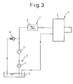
- Fig. 3 is a schematic view of a modified example of a high-pressure fuel supplying apparatus.
-
- The embodiments of the present invention will be explained using two embodiments and a modified example.
- First, the first embodiment will be explained with reference to Fig. 1. Fig. 1 is a schematic view of a high-pressure fuel supplying apparatus mounted on an accumulating fuel injection apparatus.
- The accumulating fuel injection apparatus comprises a common-rail (not shown) for accumulating a high-pressure fuel, a plurality of injectors (not shown) for injecting the high-pressure fuel accumulated in the common-rail to each cylinder of an engine (not shown), and a high-pressure fuel supplying apparatus for compressing the fuel in a fuel tank 1 to a high pressure and feeding the pressurized fuel to the common-rail.
- The high-pressure fuel supplying apparatus is, as shown in Fig. 1, provided with a high-pressure
fuel discharging system 3 having a high-pressure pump 2 for discharging the high-pressure fuel to the common-rail, a low-pressurefuel supplying system 5 having afeed pump 4 for feeding the fuel in the fuel tank 1 to the high-pressure pump 2, and a fuelsupply control system 7 having a fuel supply control valve 6 (SCV) for adjusting the amount of the fuel to be fed from thefeed pump 4 to the high-pressure pump 2. - The low-pressure
fuel supplying system 5 is provided with a regulator valve in addition to thefeed pump 4. - The
feed pump 4 is comprised of a trochoid pump, a vane pump, an external gear pump, or an internal gear pump, etc., to suck the fuel, accumulated in the fuel tank 1, through thefuel filter 9 and feed the fuel to the high-pressure pump 2 through the fuelsupply control valve 6. Thefeed pump 4 in this embodiment is driven by an electric motor (not shown) which generates a rotating force when energized. - The
regulator valve 8 is arranged in a fuel passage which connects the discharge side and the feed side of thefeed pump 4. The regulator valve opens when the discharge pressure of thefeed pump 4 increases to a predetermined pressure, so as to prevent the discharge pressure of thefeed pump 4 from exceeding the predetermined pressure. - The fuel
supply control valve 6 mounted on the fuelsupply control system 7 is an electromagnetic fuel supply control valve which controls the amount of fuel to be fed to the high-pressure pump 2 by opening/closing the fuel passage for feeding the fuel to the high-pressure pump 2, in response to an electric signal (on/off signal) supplied from an ECU (Engine Control Unit, not shown). - As the fuel
supply control valve 6 controls the fuel amount to be fed to the high-pressure pump 2, the fuel amount discharged from the high-pressure pump 2 is controlled, and the fuel pressure of the common-rail is controlled. - The high-pressure
fuel discharging system 3 is provided with anintake valve 11 and adischarge valve 12, in addition to the high-pressure pump 2. - The high-
pressure pump 2 is comprised of one or a plurality of plunger pumps driven by the engine. - The high-
pressure pump 2 of the present embodiment comprises aneccentric cam 14 which is provided on acam shaft 13 that is rotationally driven by the rotational output of the engine and rotates eccentrically with respect to a rotating axis of thecam shaft 13, acam ring 15 mounted rotatably around theeccentric cam 14, and aplunger 18 reciprocating within acylinder 17 while being pressed on the peripheral surface of thecam ring 15 by aspring 16. - When the
plunger 18 descends (moves toward the axis of rotation), a volume of apressure chamber 19 is expanded so that the pressure of thepressure chamber 19 is decreased and thedischarge valve 12 is closed. At the same time, theintake valve 11 is opened so that the fuel which is fed from thefeed pump 4 and whose amount is regulated by the fuelsupply control valve 6 is introduced into thepressure chamber 19. - Conversely, when the
plunger 18 ascends (moves in the direction opposite to the axis of rotation), the volume of thepressure chamber 19 is reduced so that the fuel in thepressure chamber 19 is pressurized and theintake valve 11 is closed. Then, when the pressure of the fuel pressurized in thepressure chamber 19 reaches a predetermined pressure, thedischarge valve 12 is opened to discharge the high-pressure fuel pressurized in thepressure chamber 19 toward the common-rail. - A part of the fuel supplied to the high-pressure
fuel discharging system 3 is supplied to acam compartment 22 which surrounds the periphery of thecam ring 15 through anorifice 21, and surplus fuel in thecam compartment 22 is returned to the fuel tank 1 through thefuel pipe 23 for returning the fuel. - Next, the features of the first embodiment will be explained. As is explained in "2. Description of the Related Art", in the conventional high-pressure fuel supplying apparatus, the high-pressure
fuel discharging system 3, the low-pressurefuel supplying system 5 and the fuelsupply control system 7 are integrally formed as a fuel injection pump. Because the high-pressure pump 2 is driven by the output of the engine, it is necessary to mount the fuel injection pump directly to the engine or in the vicinity of the engine. - However, it is not easy to provide a space large enough to mount the fuel injection pump, which is hard to downsize, near the engine in the small engine compartment.
- To this end, in the high-pressure fuel supplying apparatus of the embodiment, as shown by the dashed lines in Fig. 1, the low-pressure
fuel supplying system 5, the fuelsupply control system 7 and the high-pressurefuel discharging system 3 are independently provided as separate pieces, and are connected by thefuel pipe 23. - By separately providing the low-pressure
fuel supplying system 5, the fuelsupply control system 7 and the high-pressurefuel discharging system 3, the size of the low-pressurefuel supplying system 5, the fuelsupply control system 7 and the high-pressurefuel discharging system 3, independently from one another, can be reduced relative to the fuel injection pump. - Because the
cam shaft 13 of the high-pressure pump 2 is driven by the engine, it is necessary to provide a space for mounting the high-pressurefuel discharging system 3 near the engine. In other words, only the high-pressurefuel discharging system 3 having the high-pressure pump 2 requires a mounting space near the engine. - Because the high-pressure
fuel discharging system 3 is smaller than the fuel injection pump, it is much easier to provide a space for mounting the high-pressurefuel discharging system 3 near the engine than to provide a space for mounting the fuel injection pump, which is hard to downsize, near the engine. - On the other hand, because the feed pump is driven by an electric motor, the
feed pump 4 can be located at any place with no restriction. Also, use of the fuelsupply control valve 6 in the form of an electromagnetic fuel supply control valve makes it possible to mount the fuelsupply control valve 6 at any place. - Accordingly, as the low-pressure
fuel supplying system 5 and thesupply control system 7 have no restriction in mounting, they can be mounted in any empty space in the engine compartment. - Namely, according to the high-pressure fuel supplying apparatus of the present embodiment, the mountability to a vehicle is extremely increased compared to the prior arts.
- Also, general-purpose devices can be used for all (or some) of the
feed pump 4, the fuelsupply control valve 6 and the high-pressure pump 2. Thus, the total cost for thefeed pump 4, the fuelsupply control valve 6 and the high-pressure pump 2 can be kept low, and a low-price high-pressure fuel supplying apparatus can be provided. - Next, a second embodiment will be explained with reference to Fig. 2. The same reference numerals as those used in the first embodiment indicate like functioning components.
- In the above first embodiment, the low-pressure
fuel supplying system 5, the fuelsupply control system 7 and the high-pressurefuel discharging system 3 are independently provided as separate pieces. - Alternatively, in the high-pressure fuel supplying apparatus of the second embodiment, as shown by the dashed lines in Fig. 2, the low-pressure
fuel supplying system 5 and the fuelsupply control system 7 are integrated to be a low-pressure fuelsupply control system 24. As in the first embodiment, the high-pressurefuel discharging system 3 is provided as a separate piece. The fuelsupply control system 7 of the low-pressure fuelsupply control system 24 is connected to the high-pressurefuel discharging system 3 by thefuel pipe 23. - With this arrangement, as in the first embodiment, only the high-pressure
fuel discharging system 3, which is small relative to the fuel injection pump, should be mounted near the engine, and it becomes easier to provide a space for mounting the high-pressurefuel discharging system 3 near the engine. - On the other hand, the low-pressure fuel
supply control system 24 having, integral therewith, the low-pressurefuel supplying system 5 and the fuelsupply control system 7 has no restriction in mounting, and it can be mounted in any empty space. - Namely, the high-pressure fuel supplying apparatus of the second embodiment also has a good mountability to a vehicle, as in the first embodiment.
- As in the first embodiment, general-purpose devices can be used for all (or some) of the
feed pump 4, the fuelsupply control valve 6 and the high-pressure pump 2. Thus, the total cost for thefeed pump 4, the fuelsupply control valve 6 and the high-pressure pump 2 can be kept low, and a low-price high-pressure fuel supplying apparatus can be provided. - Lastly, a modified example will be explained. In the above-mentioned embodiments, the fuel overflowing from the
regulator valve 8 is returned to the suction side of thefeed pump 4. However, as shown in Fig. 3, the fuel overflowing from theregulator valve 8 can be returned to the fuel tank 1. - In the above embodiments, the
fuel filter 9 is arranged on the suction side of thefeed pump 4. However, as shown in Fig. 3, thefuel filter 9 can be arranged between thefeed pump 4 and the fuelsupply control valve 6. - In the above embodiments, the
feed pump 4 is driven by the electric motor so that it can be mounted in any place. However, if a space for mounting thefeed pump 4 can be obtained near the engine or the high-pressure pump 2, thefeed pump 4 can be placed in that space and driven by the torque of the engine or the high-pressure pump 2 transmitted thereto through the power transmitting means such as a gear or a chain. - While the invention has been described by reference to specific embodiments chosen for purposes of illustration, it should be apparent that numerous modifications could be made thereto, by those skilled in the art, without departing from the basic concept and scope of the invention.
- A low-pressure fuel supplying system (5), a fuel supply control system (6) and a high-pressure fuel discharging system (3) are independently provided as separate pieces, and the low-pressure fuel supplying system (5), the fuel supply control system (7) and the high-pressure fuel discharging system (3) are connected by a fuel pipe. As the high-pressure fuel discharging system (3) is small, relative to a fuel injection pump, it is easier to provide a space for mounting the high-pressure fuel discharging system (3) in the vicinity of the engine. On the other hand, as the low-pressure fuel supplying system (5) and the fuel supply control system (7) have no restriction regarding mounting position, they can be mounted in any empty space in an engine room. Accordingly, the high-pressure fuel supplying apparatus has enhanced mountability on a vehicle.
Claims (5)
- A high-pressure fuel supplying apparatus comprising
a high-pressure fuel discharging system having a high-pressure pump, which is driving by an output torque of an internal-combustion engine, for discharging a high-pressure fuel to a common rail which accumulates the high-pressure fuel,
a low-pressure fuel supplying system having a feed pump for supplying a fuel from a fuel tank to the high-pressure pump, and
a fuel supply control system having a fuel supply control valve for adjusting the amount of the fuel to be supplied from the feed pump to the high-pressure pump,
wherein the low-pressure fuel supplying system, the fuel supply control system and the high-pressure fuel discharging system are independently provided as separate pieces, and the low-pressure fuel supplying system, the fuel supply control system and the high-pressure fuel discharging system are connected by a fuel pipe. - A high-pressure fuel supplying apparatus comprising
a high-pressure fuel discharging system having a high-pressure pump, which is driving by an output torque of an internal-combustion engine, for discharging a high-pressure fuel to a common rail which accumulates the high-pressure fuel,
a low-pressure fuel supplying system having a feed pump for supplying a fuel in a fuel tank to the high-pressure pump, and
a fuel supply control system having a fuel supply control valve for adjusting an amount of the fuel to be supplied from the feed pump to the high-pressure pump,
wherein the low-pressure fuel supplying system and the fuel supply control system are integrally provided, and the high-pressure fuel discharging system is independently provided as a separate piece, and the fuel supply control system and the high-pressure fuel discharging system are connected by a fuel pipe. - A high-pressure fuel supplying apparatus according to claim 1, wherein the fuel supply control valve is an electromagnetic fuel supply control valve which opens/closes a fuel passage for feeding the fuel to the high-pressure pump, in response to an electric signal.
- A high-pressure fuel supplying apparatus according to claim 1, wherein the feed pump is driven by an electric motor.
- A high-pressure fuel supplying apparatus according to claim 1, wherein the feed pump is driven by the internal combustion engine or the high-pressure pump, through a power transmitting means such as a gear or a chain.
Applications Claiming Priority (2)
| Application Number | Priority Date | Filing Date | Title |
|---|---|---|---|
| JP2003110261A JP2004316518A (en) | 2003-04-15 | 2003-04-15 | High-pressure fuel feeder |
| JP2003110261 | 2003-04-15 |
Publications (1)
| Publication Number | Publication Date |
|---|---|
| EP1469190A1 true EP1469190A1 (en) | 2004-10-20 |
Family
ID=32906010
Family Applications (1)
| Application Number | Title | Priority Date | Filing Date |
|---|---|---|---|
| EP04008866A Withdrawn EP1469190A1 (en) | 2003-04-15 | 2004-04-14 | High-pressure fuel supplying apparatus |
Country Status (4)
| Country | Link |
|---|---|
| US (1) | US20040208753A1 (en) |
| EP (1) | EP1469190A1 (en) |
| JP (1) | JP2004316518A (en) |
| CN (1) | CN1538053A (en) |
Cited By (8)
| Publication number | Priority date | Publication date | Assignee | Title |
|---|---|---|---|---|
| EP1657434A1 (en) * | 2004-11-12 | 2006-05-17 | C.R.F. Societa' Consortile per Azioni | A high-pressure pump with a device for regulating the flow rate for a fuel-injection system |
| EP1674718A1 (en) * | 2004-12-23 | 2006-06-28 | C.R.F. Società Consortile per Azioni | Internal combustion engine storage-volume fuel injection system |
| EP1865193A1 (en) * | 2006-06-09 | 2007-12-12 | CRF Societa'Consortile per Azioni | Fuel injection system for an internal combustion engine |
| WO2009053364A1 (en) * | 2007-10-26 | 2009-04-30 | Robert Bosch Gmbh | Fuel injection system with a high-pressure pump lubricated with the fuel, and associated pump unit |
| WO2011000599A1 (en) * | 2009-06-30 | 2011-01-06 | Robert Bosch Gmbh | Fuel system for an internal combustion engine |
| EP2647824A1 (en) * | 2012-04-05 | 2013-10-09 | Delphi Technologies Holding S.à.r.l. | Injection pump systems and methods of operation |
| ITMI20131923A1 (en) * | 2013-11-20 | 2015-05-21 | Bosch Gmbh Robert | PUMPING GROUP FOR FOOD FUEL, PREFERIBLY GASOIL, FROM A CONTAINMENT TANK TO AN INTERNAL COMBUSTION ENGINE |
| CN109026470A (en) * | 2018-09-04 | 2018-12-18 | 江苏农华智慧农业科技股份有限公司 | A kind of fuel oil high voltage supply system of upper balance shaft grafting oil transfer pump |
Families Citing this family (17)
| Publication number | Priority date | Publication date | Assignee | Title |
|---|---|---|---|---|
| JP3915718B2 (en) * | 2003-03-11 | 2007-05-16 | 株式会社デンソー | Fuel supply pump |
| JP4036197B2 (en) * | 2003-04-03 | 2008-01-23 | 株式会社デンソー | Fuel supply pump |
| DE102004002459A1 (en) * | 2004-01-16 | 2005-08-11 | Siemens Ag | A method of adjusting the delivery rate of a fuel pump unit and fuel pump unit for fueling the fuel tank from the fuel tank |
| DE602005003427T2 (en) * | 2004-09-24 | 2008-09-18 | Denso Corporation, Kariya | Flow control valve |
| JP4450211B2 (en) * | 2005-01-28 | 2010-04-14 | 株式会社デンソー | Fuel supply device |
| DE102007000855B4 (en) * | 2006-12-27 | 2020-06-10 | Denso Corporation | Fuel delivery device and storage fuel injection system having this |
| JP2008180208A (en) * | 2006-12-27 | 2008-08-07 | Denso Corp | Fuel supply device |
| EP2063093A1 (en) | 2007-11-26 | 2009-05-27 | Delphi Technologies, Inc. | Fuel injection system |
| JP4475324B2 (en) * | 2007-12-21 | 2010-06-09 | 株式会社デンソー | Fuel injection pump |
| ATE487053T1 (en) * | 2008-03-04 | 2010-11-15 | Magneti Marelli Spa | COMMON RAIL DIRECT INJECTION ARRANGEMENT WITH A SHUT-OFF VALVE FOR CONTROLLING THE DELIVERY OF A HIGH PRESSURE FUEL PUMP |
| JP4930521B2 (en) * | 2009-02-02 | 2012-05-16 | 株式会社デンソー | Fuel supply device |
| JP5267446B2 (en) * | 2009-12-22 | 2013-08-21 | 日産自動車株式会社 | Fuel supply device for internal combustion engine |
| DE102011089972A1 (en) * | 2011-12-27 | 2013-06-27 | Robert Bosch Gmbh | Fuel overflow valve for a fuel injector and fuel injector with fuel spill valve |
| JP5459330B2 (en) * | 2012-01-31 | 2014-04-02 | 株式会社デンソー | Fuel supply pump |
| ITMI20120892A1 (en) * | 2012-05-23 | 2013-11-24 | Bosch Gmbh Robert | OVERFLOW VALVE AND FUEL INJECTION SYSTEM FOR AN INTERNAL COMBUSTION ENGINE COMPROMISONING OF THAT TOO FULL VALVE, |
| CN103807064B (en) * | 2014-01-26 | 2017-05-10 | 奇瑞汽车股份有限公司 | Oil supply system of optical engine |
| CN108862180B (en) * | 2018-07-05 | 2024-03-08 | 珠海格力智能装备有限公司 | Feeding system |
Citations (5)
| Publication number | Priority date | Publication date | Assignee | Title |
|---|---|---|---|---|
| EP0299337A2 (en) * | 1987-07-08 | 1989-01-18 | IVECO FIAT S.p.A. | Fuel injection system for an internal combustion engine |
| DE4444417A1 (en) * | 1994-12-14 | 1996-06-20 | Bosch Gmbh Robert | Fuel supply system |
| EP0853194A2 (en) * | 1996-12-23 | 1998-07-15 | ELASIS SISTEMA RICERCA FIAT NEL MEZZOGIORNO Società Consortile per Azioni | Pumping device for feeding fuel from a tank to an internal combustion engine |
| US6142747A (en) * | 1998-03-13 | 2000-11-07 | Robert Bosch Gmbh | Fuel pump assembly |
| EP1298316A2 (en) * | 2001-09-26 | 2003-04-02 | DEUTZ Aktiengesellschaft | Fuel injection system |
Family Cites Families (5)
| Publication number | Priority date | Publication date | Assignee | Title |
|---|---|---|---|---|
| JP2689226B2 (en) * | 1994-12-02 | 1997-12-10 | 株式会社ゼクセル | Fuel pump for high pressure fuel injector |
| DE19780251C2 (en) * | 1996-02-29 | 2001-02-22 | Mitsubishi Motors Corp | Fuel supply system for an internal combustion engine |
| DE19612412B4 (en) * | 1996-03-28 | 2006-07-06 | Siemens Ag | Control for a pressurized fluid supply system, in particular for the high pressure in a fuel injection system |
| US6024064A (en) * | 1996-08-09 | 2000-02-15 | Denso Corporation | High pressure fuel injection system for internal combustion engine |
| FR2763100B1 (en) * | 1997-05-09 | 1999-07-23 | Magneti Marelli France | RELIEF BYPASS FOR HIGH PRESSURE DIRECT INJECTION PUMP |
-
2003
- 2003-04-15 JP JP2003110261A patent/JP2004316518A/en not_active Withdrawn
-
2004
- 2004-04-05 US US10/816,898 patent/US20040208753A1/en not_active Abandoned
- 2004-04-14 EP EP04008866A patent/EP1469190A1/en not_active Withdrawn
- 2004-04-15 CN CNA2004100343845A patent/CN1538053A/en active Pending
Patent Citations (5)
| Publication number | Priority date | Publication date | Assignee | Title |
|---|---|---|---|---|
| EP0299337A2 (en) * | 1987-07-08 | 1989-01-18 | IVECO FIAT S.p.A. | Fuel injection system for an internal combustion engine |
| DE4444417A1 (en) * | 1994-12-14 | 1996-06-20 | Bosch Gmbh Robert | Fuel supply system |
| EP0853194A2 (en) * | 1996-12-23 | 1998-07-15 | ELASIS SISTEMA RICERCA FIAT NEL MEZZOGIORNO Società Consortile per Azioni | Pumping device for feeding fuel from a tank to an internal combustion engine |
| US6142747A (en) * | 1998-03-13 | 2000-11-07 | Robert Bosch Gmbh | Fuel pump assembly |
| EP1298316A2 (en) * | 2001-09-26 | 2003-04-02 | DEUTZ Aktiengesellschaft | Fuel injection system |
Cited By (14)
| Publication number | Priority date | Publication date | Assignee | Title |
|---|---|---|---|---|
| EP1657434A1 (en) * | 2004-11-12 | 2006-05-17 | C.R.F. Societa' Consortile per Azioni | A high-pressure pump with a device for regulating the flow rate for a fuel-injection system |
| US7263979B2 (en) | 2004-11-12 | 2007-09-04 | C.R.F. Societa Consortile Per Azioni | High-pressure pump with a device for regulating the flow rate for a fuel-injection system |
| EP1674718A1 (en) * | 2004-12-23 | 2006-06-28 | C.R.F. Società Consortile per Azioni | Internal combustion engine storage-volume fuel injection system |
| US7228844B2 (en) | 2004-12-23 | 2007-06-12 | C.R.F. Societa Consortile Per Azioni | Internal combustion engine storage-volume fuel injection system |
| EP1865193A1 (en) * | 2006-06-09 | 2007-12-12 | CRF Societa'Consortile per Azioni | Fuel injection system for an internal combustion engine |
| US7395812B2 (en) | 2006-06-09 | 2008-07-08 | C.R.F. Societa Consortile Per Azioni | Fuel-injection system for an internal-combustion engine |
| WO2009053364A1 (en) * | 2007-10-26 | 2009-04-30 | Robert Bosch Gmbh | Fuel injection system with a high-pressure pump lubricated with the fuel, and associated pump unit |
| WO2011000599A1 (en) * | 2009-06-30 | 2011-01-06 | Robert Bosch Gmbh | Fuel system for an internal combustion engine |
| RU2556470C2 (en) * | 2009-06-30 | 2015-07-10 | Роберт Бош Гмбх | Supply system of internal-combustion engine |
| EP2647824A1 (en) * | 2012-04-05 | 2013-10-09 | Delphi Technologies Holding S.à.r.l. | Injection pump systems and methods of operation |
| ITMI20131923A1 (en) * | 2013-11-20 | 2015-05-21 | Bosch Gmbh Robert | PUMPING GROUP FOR FOOD FUEL, PREFERIBLY GASOIL, FROM A CONTAINMENT TANK TO AN INTERNAL COMBUSTION ENGINE |
| WO2015074878A1 (en) * | 2013-11-20 | 2015-05-28 | Robert Bosch Gmbh | Pumping unit for feeding fuel, preferably diesel fuel, from a storage tank to an internal combustion engine |
| US10190553B2 (en) | 2013-11-20 | 2019-01-29 | Robert Bosch Gmbh | Pumping unit for feeding fuel, preferably diesel fuel, from a storage tank to an internal combustion engine |
| CN109026470A (en) * | 2018-09-04 | 2018-12-18 | 江苏农华智慧农业科技股份有限公司 | A kind of fuel oil high voltage supply system of upper balance shaft grafting oil transfer pump |
Also Published As
| Publication number | Publication date |
|---|---|
| US20040208753A1 (en) | 2004-10-21 |
| CN1538053A (en) | 2004-10-20 |
| JP2004316518A (en) | 2004-11-11 |
Similar Documents
| Publication | Publication Date | Title |
|---|---|---|
| EP1469190A1 (en) | High-pressure fuel supplying apparatus | |
| KR100373616B1 (en) | High-pressure fuel pump and cam for high-pressure fuel pump | |
| US7044110B2 (en) | Fuel injection device for a combustion engine | |
| US7219654B2 (en) | Fuel injection device for an internal combustion engine | |
| US8205596B2 (en) | Fuel injection device for an internal combustion engine | |
| US7118350B2 (en) | Radial piston pump | |
| US6848423B2 (en) | Fuel injection system for an internal combustion engine | |
| US20110209687A1 (en) | High-pressure fuel pump for an internal combustion engine | |
| US9422897B2 (en) | Fuel system for an internal combustion engine | |
| US7377753B2 (en) | Fuel supply pump | |
| US6976473B2 (en) | Fuel injection system for an internal combustion engine | |
| US7128054B2 (en) | Fuel injection system for an internal combustion engine | |
| JP4475324B2 (en) | Fuel injection pump | |
| US7077107B2 (en) | Fuel-injection device for an internal combustion engine | |
| JP2002155824A (en) | Fuel supply system for internal combustion engine | |
| US20050241616A1 (en) | Fuel injection device for an internal combustion engine | |
| US6959694B2 (en) | Fuel injection system for an internal combustion engine | |
| US7850435B2 (en) | Fuel injection device for an internal combustion engine | |
| US20030010319A1 (en) | Fuel injection device | |
| US6966301B2 (en) | Accumulator fuel system | |
| JP4787444B2 (en) | Radial piston pump | |
| JP2001329926A (en) | Fuel injection system | |
| JP2007211653A (en) | Fuel injection device for internal combustion engine | |
| US7406936B2 (en) | Accumulator fuel system | |
| JP4329755B2 (en) | High pressure fuel pump for internal combustion engine |
Legal Events
| Date | Code | Title | Description |
|---|---|---|---|
| PUAI | Public reference made under article 153(3) epc to a published international application that has entered the european phase |
Free format text: ORIGINAL CODE: 0009012 |
|
| AK | Designated contracting states |
Kind code of ref document: A1 Designated state(s): AT BE BG CH CY CZ DE DK EE ES FI FR GB GR HU IE IT LI LU MC NL PL PT RO SE SI SK TR |
|
| AX | Request for extension of the european patent |
Extension state: AL HR LT LV MK |
|
| 17P | Request for examination filed |
Effective date: 20041112 |
|
| 17Q | First examination report despatched |
Effective date: 20050208 |
|
| AKX | Designation fees paid |
Designated state(s): DE FR IT |
|
| STAA | Information on the status of an ep patent application or granted ep patent |
Free format text: STATUS: THE APPLICATION HAS BEEN WITHDRAWN |
|
| 18W | Application withdrawn |
Effective date: 20060126 |