JP5267446B2 - Fuel supply device for internal combustion engine - Google Patents
Fuel supply device for internal combustion engine Download PDFInfo
- Publication number
- JP5267446B2 JP5267446B2 JP2009290205A JP2009290205A JP5267446B2 JP 5267446 B2 JP5267446 B2 JP 5267446B2 JP 2009290205 A JP2009290205 A JP 2009290205A JP 2009290205 A JP2009290205 A JP 2009290205A JP 5267446 B2 JP5267446 B2 JP 5267446B2
- Authority
- JP
- Japan
- Prior art keywords
- fuel
- pressure
- pump
- pressure sensor
- value
- Prior art date
- Legal status (The legal status is an assumption and is not a legal conclusion. Google has not performed a legal analysis and makes no representation as to the accuracy of the status listed.)
- Active
Links
Images


Classifications
-
- F—MECHANICAL ENGINEERING; LIGHTING; HEATING; WEAPONS; BLASTING
- F02—COMBUSTION ENGINES; HOT-GAS OR COMBUSTION-PRODUCT ENGINE PLANTS
- F02M—SUPPLYING COMBUSTION ENGINES IN GENERAL WITH COMBUSTIBLE MIXTURES OR CONSTITUENTS THEREOF
- F02M63/00—Other fuel-injection apparatus having pertinent characteristics not provided for in groups F02M39/00 - F02M57/00 or F02M67/00; Details, component parts, or accessories of fuel-injection apparatus, not provided for in, or of interest apart from, the apparatus of groups F02M39/00 - F02M61/00 or F02M67/00; Combination of fuel pump with other devices, e.g. lubricating oil pump
- F02M63/02—Fuel-injection apparatus having several injectors fed by a common pumping element, or having several pumping elements feeding a common injector; Fuel-injection apparatus having provisions for cutting-out pumps, pumping elements, or injectors; Fuel-injection apparatus having provisions for variably interconnecting pumping elements and injectors alternatively
- F02M63/0205—Fuel-injection apparatus having several injectors fed by a common pumping element, or having several pumping elements feeding a common injector; Fuel-injection apparatus having provisions for cutting-out pumps, pumping elements, or injectors; Fuel-injection apparatus having provisions for variably interconnecting pumping elements and injectors alternatively for cutting-out pumps or injectors in case of abnormal operation of the engine or the injection apparatus, e.g. over-speed, break-down of fuel pumps or injectors ; for cutting-out pumps for stopping the engine
-
- F—MECHANICAL ENGINEERING; LIGHTING; HEATING; WEAPONS; BLASTING
- F02—COMBUSTION ENGINES; HOT-GAS OR COMBUSTION-PRODUCT ENGINE PLANTS
- F02D—CONTROLLING COMBUSTION ENGINES
- F02D41/00—Electrical control of supply of combustible mixture or its constituents
- F02D41/22—Safety or indicating devices for abnormal conditions
- F02D41/222—Safety or indicating devices for abnormal conditions relating to the failure of sensors or parameter detection devices
-
- F—MECHANICAL ENGINEERING; LIGHTING; HEATING; WEAPONS; BLASTING
- F02—COMBUSTION ENGINES; HOT-GAS OR COMBUSTION-PRODUCT ENGINE PLANTS
- F02D—CONTROLLING COMBUSTION ENGINES
- F02D41/00—Electrical control of supply of combustible mixture or its constituents
- F02D41/30—Controlling fuel injection
- F02D41/38—Controlling fuel injection of the high pressure type
- F02D41/3809—Common rail control systems
- F02D41/3836—Controlling the fuel pressure
- F02D41/3845—Controlling the fuel pressure by controlling the flow into the common rail, e.g. the amount of fuel pumped
-
- F—MECHANICAL ENGINEERING; LIGHTING; HEATING; WEAPONS; BLASTING
- F02—COMBUSTION ENGINES; HOT-GAS OR COMBUSTION-PRODUCT ENGINE PLANTS
- F02M—SUPPLYING COMBUSTION ENGINES IN GENERAL WITH COMBUSTIBLE MIXTURES OR CONSTITUENTS THEREOF
- F02M63/00—Other fuel-injection apparatus having pertinent characteristics not provided for in groups F02M39/00 - F02M57/00 or F02M67/00; Details, component parts, or accessories of fuel-injection apparatus, not provided for in, or of interest apart from, the apparatus of groups F02M39/00 - F02M61/00 or F02M67/00; Combination of fuel pump with other devices, e.g. lubricating oil pump
- F02M63/02—Fuel-injection apparatus having several injectors fed by a common pumping element, or having several pumping elements feeding a common injector; Fuel-injection apparatus having provisions for cutting-out pumps, pumping elements, or injectors; Fuel-injection apparatus having provisions for variably interconnecting pumping elements and injectors alternatively
- F02M63/0225—Fuel-injection apparatus having a common rail feeding several injectors ; Means for varying pressure in common rails; Pumps feeding common rails
- F02M63/023—Means for varying pressure in common rails
- F02M63/0235—Means for varying pressure in common rails by bleeding fuel pressure
- F02M63/0245—Means for varying pressure in common rails by bleeding fuel pressure between the high pressure pump and the common rail
-
- F—MECHANICAL ENGINEERING; LIGHTING; HEATING; WEAPONS; BLASTING
- F02—COMBUSTION ENGINES; HOT-GAS OR COMBUSTION-PRODUCT ENGINE PLANTS
- F02D—CONTROLLING COMBUSTION ENGINES
- F02D41/00—Electrical control of supply of combustible mixture or its constituents
- F02D41/22—Safety or indicating devices for abnormal conditions
- F02D41/222—Safety or indicating devices for abnormal conditions relating to the failure of sensors or parameter detection devices
- F02D2041/223—Diagnosis of fuel pressure sensors
-
- F—MECHANICAL ENGINEERING; LIGHTING; HEATING; WEAPONS; BLASTING
- F02—COMBUSTION ENGINES; HOT-GAS OR COMBUSTION-PRODUCT ENGINE PLANTS
- F02D—CONTROLLING COMBUSTION ENGINES
- F02D2200/00—Input parameters for engine control
- F02D2200/02—Input parameters for engine control the parameters being related to the engine
- F02D2200/06—Fuel or fuel supply system parameters
- F02D2200/0602—Fuel pressure
Abstract
Description
本発明は、内燃機関の燃料供給系の圧力制御装置に関する。 The present invention relates to a pressure control device for a fuel supply system of an internal combustion engine.
筒内直噴式の火花点火式内燃機関において、燃料噴霧をより微細化するためには高い噴射圧力が要求される。そこで、燃料タンク内の燃料を低圧側の電磁式燃料ポンプ(低圧ポンプ)で圧送し、この低圧の燃料を高圧側の機械式燃料ポンプ(高圧ポンプ)で高圧にしてコモンレールに蓄え、コモンレール内の燃料圧力(燃料噴射圧)に応じた噴射パルスで燃焼室内に噴射する燃料供給装置が知られている。そして、燃料噴射圧を内燃機関の運転状態に応じて設定した目標噴射圧に保つため、一般的に、圧力センサの検出値に基づいてフィードバック制御が行われる。 In a direct injection type spark ignition internal combustion engine, a high injection pressure is required in order to further refine fuel spray. Therefore, the fuel in the fuel tank is pumped by the low-pressure side electromagnetic fuel pump (low-pressure pump), and this low-pressure fuel is made high-pressure by the high-pressure side mechanical fuel pump (high-pressure pump) and stored in the common rail. 2. Description of the Related Art There is known a fuel supply device that injects fuel into a combustion chamber with an injection pulse corresponding to a fuel pressure (fuel injection pressure). In order to maintain the fuel injection pressure at the target injection pressure set according to the operating state of the internal combustion engine, feedback control is generally performed based on the detection value of the pressure sensor.
ところで、上記のような燃料供給装置において、燃料噴射圧を検出する圧力センサ(高圧燃圧センサ)が断線等により正確な値を示さない場合には、燃料噴射圧を正確に制御することができなくなる。 By the way, in the fuel supply apparatus as described above, when the pressure sensor (high pressure fuel pressure sensor) for detecting the fuel injection pressure does not show an accurate value due to disconnection or the like, the fuel injection pressure cannot be accurately controlled. .
そこで、特許文献1では、高圧燃圧センサが断線等した場合には、高圧ポンプを最大吐出量状態に制御して、燃料噴射圧が機構上の最大値であると推定することとしている。
Therefore, in
しかしながら、特許文献1に記載されている制御では、高圧ポンプを最大吐出圧に設定してから実際の燃料噴射圧が最大値になるまでの間、実際の燃料噴射圧よりも高い燃料噴射圧に基づいて噴射パルスが算出される。燃料噴射量が同じ場合には燃料噴射圧が高いほど噴射パルスは短くなるので、実際の燃料噴射圧よりも高い燃料噴射圧に基づいて噴射パルスを算出すると、必要な燃料量を噴射しきれない噴射パルスが設定されてしまう。このため、リーン失火を招くおそれがあり、エンジンストールに至るおそれもある。
However, in the control described in
そこで、本発明では高圧センサが断線等した場合にも、実燃圧に応じた適切な噴射パルスで燃料噴射を行うよう燃料噴射圧制御し得る制御装置を提供することを目的とする。 Accordingly, an object of the present invention is to provide a control device capable of controlling the fuel injection pressure so that fuel injection is performed with an appropriate injection pulse corresponding to the actual fuel pressure even when the high-pressure sensor is disconnected.
本発明の内燃機関の燃料供給装置は、燃料タンクから燃料を吸い上げる低圧燃料ポンプと、低圧燃料ポンプから吐出された燃料を加圧する高圧燃料ポンプと、高圧燃料ポンプに加圧された燃料を蓄える蓄圧室とを備える。また、蓄圧室に蓄えられた燃料を内燃機関の筒内に直接噴射する燃料噴射弁と、蓄圧室内の燃圧の上限値を制限するリリーフバルブと、蓄圧室内の燃圧を検出する高圧燃圧センサを備える。さらに、機関運転状態に応じた目標燃料噴射圧を設定し、高圧燃圧センサの検出値と目標燃料噴射圧に基づいて蓄圧室の燃圧が目標燃料噴射圧となるように高圧燃料ポンプを制御する燃圧制御手段を有する。そして、燃圧制御手段は高圧燃圧センサがはずれ値を検出した時間が予め設定した閾値を超えた場合に高圧燃圧センサに異常ありと判定し、高圧燃圧センサに異常ありと判定した場合には、高圧燃料ポンプを最大吐出量での作動状態または高圧燃料ポンプを非作動状態にし、異常ありと判定したときの目標燃料噴射圧を高圧燃圧センサの検出値とみなして、高圧燃圧センサの検出値とみなした値に基づいて燃料噴射弁の燃料噴射パルス幅を設定する。 A fuel supply device for an internal combustion engine according to the present invention includes a low-pressure fuel pump that sucks fuel from a fuel tank, a high-pressure fuel pump that pressurizes fuel discharged from the low-pressure fuel pump, and an accumulator that stores pressurized fuel in the high-pressure fuel pump Room. Also, a fuel injection valve that directly injects fuel stored in the pressure accumulating chamber into the cylinder of the internal combustion engine, a relief valve that limits the upper limit value of the fuel pressure in the pressure accumulating chamber, and a high-pressure fuel pressure sensor that detects the fuel pressure in the pressure accumulating chamber . Further, a fuel pressure that sets a target fuel injection pressure according to the engine operating state and controls the high-pressure fuel pump so that the fuel pressure in the accumulator becomes the target fuel injection pressure based on the detected value of the high-pressure fuel pressure sensor and the target fuel injection pressure It has a control means. When the fuel pressure control means for determining that there is an abnormality in the high-pressure fuel pressure sensor when the threshold is exceeded the time of detecting the outliers high pressure fuel pressure sensor is preset, it is determined that there is abnormality in the high-pressure fuel pressure sensor, high pressure the fuel pump also operating state at the maximum discharge amount is high pressure fuel pump inoperative, the goals fuel injection pressure when it is determined there is an abnormality is regarded as the detection value of the high圧燃pressure sensor, high圧燃pressure sensor setting the fuel injection pulse width of the fuel injection valve based on the detected value and the value was considered the.
本発明によれば、高圧燃圧センサが断線等によりコモンレール内の燃圧を正確に検出しなくなった場合でも、実燃圧を精度よく検知することができるので、実燃圧に応じた適切な噴射パルス幅で燃料噴射することができる。 According to the present invention, even when the high-pressure fuel pressure sensor cannot accurately detect the fuel pressure in the common rail due to disconnection or the like, the actual fuel pressure can be detected with high accuracy, so that an appropriate injection pulse width corresponding to the actual fuel pressure can be obtained. Fuel can be injected.
以下本発明の実施形態を図面に基づいて説明する。 Hereinafter, embodiments of the present invention will be described with reference to the drawings.
図1は、本発明の第1実施形態を適用する、内燃機関の燃料供給装置の構成図である。ここでの内燃機関は、筒内直噴火花点火式内燃機関である。 FIG. 1 is a configuration diagram of a fuel supply device for an internal combustion engine to which the first embodiment of the present invention is applied. The internal combustion engine here is an in-cylinder direct injection spark ignition internal combustion engine.
燃料タンク1内に、モータ9で駆動される低圧燃料ポンプ8が設けられている。詳しくは、燃料タンク1内の燃料を圧送する低圧燃料ポンプ8と、その吐出側で燃料をろ過する燃料フィルタ20と、余剰燃料を燃料タンク1へ戻すことで吐出側圧力を一定圧力(通常0.3〜0.5MPa程度)に調整する低圧プレッシャレギュレータ10とが設けられている。
A low
低圧燃料ポンプ8により圧送される燃料は、低圧燃料通路22により燃料フィルタ21及び燃料ダンパ11を介して、高圧燃料ポンプ2へ供給される。低圧燃料通路22には通路内の燃料圧力を検出する低圧燃圧センサ5が設けられ、その信号(燃圧センサ電圧値)はコントロールユニット(ECU)7に入力され、入力された電圧値は圧力値(燃圧センサ指示値)に変換される。
The fuel pumped by the low
高圧燃料ポンプ2は主にプランジャポンプ2aにより構成されている。プランジャポンプ2aは、カム14によってプランジャ15をスプリング18の付勢力に抗して往復動させることにより、ポンプ室19の容積を変化させ、プランジャ15の吸入行程にて吸入側一方向弁13を介してポンプ室19内に燃料を吸入し、プランジャ15の吐出行程(プランジャ15が下死点を通過して上昇する行程)にて吐出側一方向弁16を介してポンプ室19内の燃料を吐出する。なお、カム14は内燃機関のカムシャフトに連結されている。
The high-
高圧燃料ポンプ2の吐出側は蓄圧室としてのコモンレール3に接続されており、コモンレール3には内燃機関の各気筒の燃焼室に臨む燃料噴射弁4が接続されている。したがって、高圧燃料ポンプ2から吐出された燃料は、コモンレール3に流入し、そこから内燃機関の各気筒に設けられた燃料噴射弁4を介して筒内に噴射される。また、コモンレール3には、コモンレール3内の燃圧を検出する高圧燃圧センサ6が取り付けられ、その信号(燃圧センサ電圧値)はECU7に入力され、入力された電圧値は圧力値(燃圧センサ指示値)に変換される。なお、低圧燃圧センサ5及び高圧燃圧センサ6の燃圧センサ電圧値は、いずれも燃圧センサ指示値と比例関係にある。
The discharge side of the high-
高圧燃料ポンプ2は、さらにソレノイド12を含んで構成されている。ソレノイド12は、吸入側一方向弁13を挟んでプランジャポンプ2aと反対側に設けられ、通電により発生する電磁力により、ポンプ室19内の圧力にかかわらず、吸入側一方向弁13を開弁状態に保持することができる。したがって、プランジャポンプ2aの吐出行程のいずれのタイミングでソレノイド12への通電を終了するかによって、プランジャポンプ2aの吐出動作の開始時期、すなわち吐出量を制御することができる。
The high-
また、吐出側一方向弁16とコモンレール3の間の高圧燃料配管23は、分岐してリターン配管24となる。リターン配管24にはリリーフバルブ17が介装されており、高圧燃料配管23内の圧力が一定圧力(例えば15MPa程度)を超えるとリリーフバルブ17が開弁し、燃料の一部を燃料ダンパ11とソレノイド12の間に戻す。これにより、コモンレール3内の圧力が一定圧力を超えて高圧になることを防止できる。つまり、燃料噴射弁4から噴射する燃圧(燃料噴射圧)の上限値を制限することができる。
Further, the high-
ここで、燃料噴射弁4から噴射する燃料圧力を制御するための、コモンレール3内の燃圧制御について説明する。 Here, the fuel pressure control in the common rail 3 for controlling the fuel pressure injected from the fuel injection valve 4 will be described.
燃圧は、ECU7からの信号により、ソレノイド12の通電終了タイミング(吐出行程における吸入側一方向弁13の閉弁タイミング)を制御して、高圧燃料ポンプ2の吐出量を制御することにより、ポンプ吐出量と燃料噴射量との流量収支のバランスで後述する目標燃圧にフィードバック制御する。具体的には、運転状態に応じた燃料噴射量での運転中に、高圧燃圧センサ6の検出値と目標燃圧との乖離がなくなるようにポンプ吐出量をフィードバック制御する。
The fuel pressure is controlled by a signal from the ECU 7 by controlling the end of energization of the solenoid 12 (the closing timing of the suction-side one-
目標燃圧は、ECU7が運転条件(機関回転速度及び負荷)に応じて設定する。例えば図4に示すような、機関負荷が同じなら機関回転速度が高い領域の方が低い領域よりも目標燃圧が高く、機関回転速度が同じなら機関負荷が大きくなるほど目標燃圧が高く設定されたマップを参照することで設定する。 The target fuel pressure is set by the ECU 7 in accordance with operating conditions (engine speed and load). For example, as shown in FIG. 4, a map in which the target fuel pressure is higher in the region where the engine speed is high than in the low region if the engine load is the same, and the target fuel pressure is set higher as the engine load increases if the engine speed is the same. Set by referring to.
燃料噴射弁4からの燃料噴射量の目標値(目標燃料噴射量)は、ECU7が運転条件(機関回転速度及び負荷)に応じて設定する。そして、ECU7は目標燃料噴射量を目標燃圧のもとで噴射するための噴射時間(噴射パルス)を算出し、算出された噴射パルスに基づいて燃料噴射弁4の開弁時間を制御する。例えば、目標燃料噴射量が同じでも、目標燃圧が高いほど噴射パルスは短く、逆に目標燃圧が低いほど噴射パルスは長くなる。 The target value (target fuel injection amount) of the fuel injection amount from the fuel injection valve 4 is set by the ECU 7 according to the operating conditions (engine speed and load). The ECU 7 calculates an injection time (injection pulse) for injecting the target fuel injection amount under the target fuel pressure, and controls the valve opening time of the fuel injection valve 4 based on the calculated injection pulse. For example, even if the target fuel injection amount is the same, the higher the target fuel pressure, the shorter the injection pulse. Conversely, the lower the target fuel pressure, the longer the injection pulse.
ところで、高圧燃圧センサ6が断線等によって正確な燃圧を検出できなくなると、次のような弊害が生じる。
By the way, when the high-pressure
高圧燃圧センサ6が断線すると、高圧燃圧センサ6からECU7へ最大燃圧を示す信号が入力される。このため、実際の燃圧に基づいた噴射パルスよりも短い噴射パルスが設定されて、目標燃料噴射量を噴射しきれなくなる。また、見かけ上は目標燃圧との乖離が大きくなるので、ECU7は上述したフィードバック制御により燃圧を下げるように高圧燃料ポンプ2を作動させ、実際の燃圧が低下する。このように、ECU7は噴射パルスを必要な噴射パルスより短く設定し、さらに実燃圧も低くするような制御を行うので、必要な燃料量が噴射されなくなり、リーン失火やエンジンストールに至るおそれが生じる。
When the high-pressure
そこで、ECU7は、高圧燃圧センサ6がコモンレール3内の燃圧を正確に検出できなくなった場合にもリーン失火やエンジンストールを回避するために、以下に説明する制御を実行する。
Therefore, the ECU 7 executes the control described below in order to avoid lean misfire and engine stall even when the high-pressure
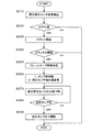
図2はECU7が実行する制御ルーチンを示すフローチャートである。本制御ルーチンは、例えば数ミリ秒間隔で繰り返し実行する。 FIG. 2 is a flowchart showing a control routine executed by the ECU 7. This control routine is repeatedly executed at intervals of, for example, several milliseconds.
ステップS110では、高圧燃圧センサ6からの燃圧センサ電圧値を読み込む。
In step S110, the fuel pressure sensor voltage value from the high pressure
ステップS120では、読み込んだ燃圧センサ電圧値から変換した燃圧センサ指示値が、はずれ値か否かを判定する。ここでいう「はずれ値」とは、断線等がない運転時(通常運転時)に高圧燃圧センサ6から入力される電圧値の範囲を超えた値のことをいう。例えば、高圧燃圧センサ6の計測レンジが0〜5[V]の場合に、通常運転時に使用するのは0.5〜4.5[V]の範囲とし、この範囲を外れた値を「はずれ値」とする。この場合、高圧燃圧センサ6がショートしている場合は通常運転時の使用レンジより小さい側に外れた値、断線している場合は通常運転時の使用レンジより大きい側に外れた値となる。
In step S120, it is determined whether or not the fuel pressure sensor instruction value converted from the read fuel pressure sensor voltage value is an outlier. The “outlier value” here refers to a value that exceeds the range of the voltage value input from the high-pressure
はずれ値でない場合はそのまま処理を終了し、はずれ値の場合はステップS130へ進む。 If it is not an outlier, the process is terminated as it is, and if it is an outlier, the process proceeds to step S130.
ステップS130では、はずれ値を検出した時間のカウントを開始し、ステップS140ではカウンタ値が予め設定した閾値を超えたか否かを判定する。閾値は、例えば10ミリ秒程度に設定する。 In step S130, counting of the time when the outlier is detected is started, and in step S140, it is determined whether or not the counter value exceeds a preset threshold value. The threshold is set to about 10 milliseconds, for example.
閾値を超えていない場合はそのまま処理を終了し、超えている場合はステップS150へ進みフェールセーフ制御の開始を決定する。 If it does not exceed the threshold, the process is terminated as it is. If it exceeds, the process proceeds to step S150 to determine the start of failsafe control.
はずれ値を検出したときに直ちにフェールセーフ制御の開始を決定せずに、閾値を超えるまでカウントするのは、燃圧センサ電圧値がノイズの発生により大きくなった際に誤診断することを防止するためである。 Counting until the threshold value is exceeded without immediately deciding to start fail-safe control when an outlier is detected is to prevent misdiagnosis when the fuel pressure sensor voltage value increases due to noise. It is.
ステップS160では、高圧燃料ポンプ2の吐出量を最大に設定し、かつ高圧燃圧センサ6の燃圧センサ指示値を、現在の目標燃料噴射圧に変更する。
In step S160, the discharge amount of the high
高圧燃料ポンプ2の吐出量を最大に設定すれば、コモンレール3内の燃圧は上昇してリリーフバルブ17のリリーフ圧に到達し、リリーフバルブ17が開弁してコモンレール3内の燃圧は一定となる。したがって、リリーフ圧に到達した状態であれば、高圧燃圧センサ6で検出することなくコモンレール3内の正確な燃圧を把握することができる。
If the discharge amount of the high-
また、目標燃料噴射圧を現在の噴射圧に変更するのは、ステップS150でフェールセーフ制御開始を決定した時点でのコモンレール3内の燃圧は、フェールセーフ制御開始を決定する直前の燃圧からほとんど変動していないからである。すなわち、フェールセーフ制御開始を決定するまでは、コモンレール3内の燃圧はフィードバック制御によって目標燃料噴射圧となっているので、燃圧センサ指示値を現在の目標燃料噴射圧に変更すれば、フェールセーフ制御開始決定時におけるコモンレール3内の燃圧をほぼ正確に把握することができる。 In addition, the target fuel injection pressure is changed to the current injection pressure because the fuel pressure in the common rail 3 at the time when the start of the failsafe control is determined in step S150 is almost changed from the fuel pressure immediately before the start of the failsafe control. It is because it is not. That is, until the start of fail-safe control is determined, the fuel pressure in the common rail 3 becomes the target fuel injection pressure by feedback control. Therefore, if the fuel pressure sensor instruction value is changed to the current target fuel injection pressure, fail-safe control is performed. The fuel pressure in the common rail 3 at the time of starting determination can be grasped almost accurately.
ステップS170では、高圧燃圧センサ6の燃圧センサ指示値を、例えば機関回転速度に応じて上昇させる。高圧燃料ポンプ2の吐出量を最大にすることで、コモンレール3内の燃圧は上昇するので、現在の目標燃料噴射圧に変更した燃圧センサ指示値も増大させることで、実燃圧と燃圧センサ指示値との乖離を小さく抑えることができる。そして、後述するように燃圧センサ指示値がリリーフ圧まで上昇するまでステップS170は繰り返し実行されるので、ステップS170が繰り返し実行されることにより、燃圧センサ指示値が徐々に増大する。これにより、ステップS160で高圧燃料ポンプ2の吐出量を最大に設定してから、コモンレール3内の実燃圧がリリーフ圧に到達するまで、実燃圧を精度よく把握することができる。
In step S170, the fuel pressure sensor instruction value of the high-pressure
コモンレール3内の燃圧の上昇は高圧燃料ポンプ2の吐出回数に依存し、この吐出回数は機関回転速度に依存する。すなわち、コモンレール3内の燃圧の上昇速度は、機関回転速度が高くなるほど速く、機関回転速度が低くなるほど遅くなる。したがって、燃圧センサ指示値を機関回転速度に応じて上昇させれば、高圧燃圧センサ6によらずに、燃圧上昇中の実燃圧を精度よく把握することができる。
The increase in the fuel pressure in the common rail 3 depends on the number of discharges of the high-
ステップS180では、燃圧センサ指示値がリリーフ圧まで上昇したか否かを判定し、上昇していなければステップS170に戻り、上昇していればステップS190に進んで燃圧センサ指示値をリリーフ圧に固定する。リリーフ圧に達すれば、高圧燃料ポンプ2の吐出量が最大のままであってもリリーフバルブ17が開弁するので、実燃圧は最大値を維持するからである。
In step S180, it is determined whether or not the fuel pressure sensor instruction value has increased to the relief pressure. If not, the process returns to step S170, and if it has increased, the process proceeds to step S190 to fix the fuel pressure sensor instruction value to the relief pressure. To do. This is because if the relief pressure is reached, the
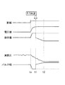
上述した制御ルーチンを実行した場合のタイムチャートを図3に示す。 FIG. 3 shows a time chart when the above-described control routine is executed.
t0で高圧燃圧センサ6が断線すると、燃圧センサ電圧値が増大し、これに伴って燃圧センサ指示値も増大して最大値に張り付く。この間、燃圧センサ指示値と目標燃料噴射圧との乖離が大きくなるので、フィードバック制御によって高圧燃料ポンプ2の吐出量は減少し、コモンレール3内の実燃圧は低下する。一方、燃圧センサ指示値が最大値まで増大したため、運転状態に応じて定まる目標燃料噴射量を噴射するための燃料噴射のパルス幅は、最小パルス幅まで小さくなる。
When the high-pressure
このため、燃圧センサ指示値を最大値のままにしておくと、実燃圧の低下が進むにつれて燃料噴射量は目標噴射量に対して少なくなり(図中の破線)、リーン失火が生じやすくなり、実燃圧が最大値に達する前にエンジンストールしてしまう。 For this reason, if the fuel pressure sensor instruction value is left at the maximum value, the fuel injection amount decreases with respect to the target injection amount as the actual fuel pressure decreases (broken line in the figure), and lean misfire tends to occur. The engine stalls before the actual fuel pressure reaches the maximum value.
これに対して本実施形態では、t1でフェールセーフ制御開始を決定したら(S110〜S150)、燃圧センサ指示値を現在の目標燃料噴射圧に変更する(S160)。これにより、燃圧センサ指示値は実燃圧に近い値に戻り、その結果噴射パルス幅も実燃圧に応じた適正値に近づく。 On the other hand, in this embodiment, when the fail safe control start is determined at t1 (S110 to S150), the fuel pressure sensor instruction value is changed to the current target fuel injection pressure (S160). Thereby, the fuel pressure sensor instruction value returns to a value close to the actual fuel pressure, and as a result, the injection pulse width also approaches an appropriate value according to the actual fuel pressure.
また、高圧燃料ポンプ2の吐出量を最大にして(S160)、そこから機関回転速度に応じて燃圧センサ指示値を上昇させる(S170)。これにより燃圧センサ指示値はコモンレール3内の実燃圧の上昇に伴って増大することとなるので、実燃圧に応じた適切な噴射パルス幅が設定される。つまり、目標燃料噴射量が噴射されるので、リーン失火を回避できる。
Further, the discharge amount of the high-
そして、t2で機関回転速度に応じて上昇させてきた燃圧センサ指示値がリリーフ圧に達したら、燃圧センサ指示値を最大値に固定する(S180、S190)。この状態では、実燃圧も最大値に達しているので、噴射パルス幅が小さくても十分な燃料噴射量を確保することができる。 Then, when the fuel pressure sensor instruction value raised according to the engine speed at t2 reaches the relief pressure, the fuel pressure sensor instruction value is fixed to the maximum value (S180, S190). In this state, since the actual fuel pressure has also reached the maximum value, a sufficient fuel injection amount can be ensured even if the injection pulse width is small.
このように、高圧燃圧センサ6が断線した場合でも、実燃圧に応じた適切な噴射パルス幅で燃料噴射することができる。
Thus, even when the high-pressure
なお、燃圧センサ指示値を目標燃料噴射圧に変更した時点における、目標燃料噴射圧と実燃圧とにずれがあると、機関回転速度に応じて算出した燃圧センサ指示値がリリーフ圧に達するタイミングと実燃圧がリリーフ圧に達するタイミングとにずれが生じることがある。しかし、高圧燃料ポンプ2を最大吐出圧で運転していることにより実燃圧は確実にリリーフ圧に達するので、結果的には燃圧センサ指示値と実燃圧とが一致する。
If there is a difference between the target fuel injection pressure and the actual fuel pressure when the fuel pressure sensor instruction value is changed to the target fuel injection pressure, the timing at which the fuel pressure sensor instruction value calculated according to the engine speed reaches the relief pressure There may be a difference between the timing when the actual fuel pressure reaches the relief pressure. However, since the actual fuel pressure reliably reaches the relief pressure by operating the high-
以上により本実施形態では次の効果を得ることができる。 As described above, the following effects can be obtained in the present embodiment.
(1)ECU7は、高圧燃圧センサ6の異常を検知した場合に、現在の目標燃料噴射圧を高圧燃圧センサ6の検出値とみなし、かつ高圧燃料ポンプ2を最大吐出量での作動状態にするので、異常検知時における実燃圧に応じた適切な噴射パルス幅で燃料噴射することができる。
(1) When the ECU 7 detects an abnormality in the high-pressure
(2)ECU7は、高圧燃料ポンプ2を最大吐出量での作動状態にする場合に、現在の目標燃料噴射圧に置き換えた燃圧センサ指示値を連続的に増大させるので、実燃圧の上昇に応じた噴射パルス幅を設定することができる。
(2) The ECU 7 continuously increases the fuel pressure sensor instruction value replaced with the current target fuel injection pressure when the high-
(3)ECU7は、現在の目標燃料噴射圧に置き換えた燃圧センサ指示値の増大速度を、機関回転速度が高いほど速く、機関回転速度が低いほど低くするので、実燃圧がリリーフ圧まで上昇する間、実燃圧と燃圧センサ指示値との乖離を抑え、適切な噴射パルス幅で燃料噴射することができる。 (3) Since the ECU 7 increases the increase speed of the fuel pressure sensor instruction value replaced with the current target fuel injection pressure as the engine rotation speed increases and decreases as the engine rotation speed decreases, the actual fuel pressure increases to the relief pressure. In the meantime, the difference between the actual fuel pressure and the fuel pressure sensor instruction value is suppressed, and fuel can be injected with an appropriate injection pulse width.
なお、上記説明では、高圧燃圧センサ6が断線した場合について説明したが、ショートした場合にも同様に適用することができる。ショートした場合は、図3のt0〜t1に相当する部分のチャートが、図3のチャートを上下に反転した形となるだけで、t1以降については図3と同様である。
In the above description, the case where the high-pressure
つまり、t0〜t1では、燃圧センサ電圧値の下降に伴って燃圧センサ指示値も低下して最小値に張り付く。この間、実燃圧はフィードバック制御により増大するが、燃圧指示値が低下しているため、噴射パルス幅は増大する。つまり燃料噴射量が過剰になり、排気性能や燃費性能の悪化を招く。 That is, at t0 to t1, the fuel pressure sensor instruction value also decreases as the fuel pressure sensor voltage value decreases and sticks to the minimum value. During this time, the actual fuel pressure increases due to the feedback control, but the injection pulse width increases because the fuel pressure instruction value decreases. That is, the fuel injection amount becomes excessive, and the exhaust performance and the fuel consumption performance are deteriorated.
また、筒内直噴火花点火式内燃機関について説明したが、いわゆるコモンレール式の筒内直噴圧縮自己着火内燃機関についても同様に適用することができる。 The in-cylinder direct-injection spark-ignition internal combustion engine has been described. However, the present invention can be similarly applied to a so-called common rail in-cylinder direct-injection compression self-ignition internal combustion engine.
第2実施形態について説明する。 A second embodiment will be described.
本実施形態は、第1実施形態と燃料供給装置の構成は同様であるが、高圧燃圧センサ6が断線等した場合の制御が一部異なる。そこで、異なる部分を中心に説明する。
In the present embodiment, the configuration of the fuel supply device is the same as that of the first embodiment, but the control when the high-pressure
図5は、ECU7が実行する制御ルーチンを示すフローチャートである。ステップS210〜S250までは図2のステップS110〜S150と同様なので説明を省略する。 FIG. 5 is a flowchart showing a control routine executed by the ECU 7. Steps S210 to S250 are the same as steps S110 to S150 in FIG.
フェールセーフ制御実行を決定したら、ステップS260に進み、高圧燃料ポンプ2の作動を停止し、かつ高圧燃圧センサ6の燃圧センサ指示値を、現在の目標燃料噴射圧に変更する。
If execution of fail safe control is decided, it will progress to Step S260, operation of high
高圧燃料ポンプ2を非作動にすれば、コモンレール3内の燃圧は燃料噴射を行う度に低下し、やがて低圧燃料ポンプ8のみによる圧力(低圧ポンプ圧)まで低下する。したがって、低圧ポンプ圧に到達した状態であれば、高圧燃圧センサ6で検出することなくコモンレール3内の正確な燃圧を把握することができる。
If the high-
高圧燃圧センサ6の燃圧センサ指示値を、現在の目標燃料噴射圧に変更するのは、図2のステップS160と同様の理由による。
The reason why the fuel pressure sensor instruction value of the high pressure
ステップS270では、高圧燃圧センサ指示値を、例えば燃料噴射量に応じて低下させる。これは、ステップS260で高圧燃料ポンプ2を非作動にしてから、コモンレール3内の実燃圧が低圧ポンプ圧に到達するまで、実燃圧を精度よく把握するためである。
In step S270, the high-pressure fuel pressure sensor instruction value is reduced, for example, according to the fuel injection amount. This is because the actual fuel pressure is accurately grasped until the actual fuel pressure in the common rail 3 reaches the low pressure pump pressure after the high
コモンレール3内には減圧弁等は設けられていないので、高圧燃料ポンプ2を非作動にしただけでは燃圧は低下せず、燃料噴射弁4から燃料を噴射することによって低下する。つまり、燃料噴射量が多いほどコモンレール3内の燃圧低下は早く、燃料噴射量が少ないほど燃圧低下は遅くなる。したがって、燃圧センサ指示値を燃料噴射量に応じて低下させれば、高圧燃圧センサ6によらずに、燃圧低下中の実燃圧を精度よく把握することができる。
Since no pressure reducing valve or the like is provided in the common rail 3, the fuel pressure does not decrease just by disabling the high
上述した制御ルーチンを実行した場合のタイムチャートを図6に示す。 FIG. 6 shows a time chart when the above-described control routine is executed.
t1でフェールセーフ制御開始を決定したら(S210〜S250)、燃圧センサ指示値を現在の目標燃料噴射圧に変更する(S260)。これにより、燃圧センサ指示値は実燃圧に近い値に戻り、その結果噴射パルス幅も断線前の値に近づく。 When fail-safe control start is determined at t1 (S210 to S250), the fuel pressure sensor instruction value is changed to the current target fuel injection pressure (S260). Thereby, the fuel pressure sensor instruction value returns to a value close to the actual fuel pressure, and as a result, the injection pulse width also approaches the value before the disconnection.
また、高圧燃料ポンプ2を非作動にして(S260)、そこから燃料噴射量に応じて燃圧センサ指示値を低下させる(S270)。これにより燃圧センサ指示値はコモンレール3内の実燃圧の低下に伴って減少することとなるので、実燃圧に応じた適切な噴射パルス幅が設定される。つまり、目標燃料噴射量が噴射されるので、リーン失火を回避できる。
Further, the high-
そして、t2で燃圧センサ指示値が低圧ポンプ圧に達したら、燃圧センサ指示値を低圧ポンプ圧に固定する(S280、S290)。この状態では、実燃圧も低圧ポンプに達しているので、大きな噴射パルス幅が設定されることで十分な燃料噴射量を確保することができる。 When the fuel pressure sensor instruction value reaches the low pressure pump pressure at t2, the fuel pressure sensor instruction value is fixed to the low pressure pump pressure (S280, S290). In this state, since the actual fuel pressure has reached the low pressure pump, a sufficient fuel injection amount can be secured by setting a large injection pulse width.
このように、高圧燃圧センサ6が断線した場合でも、実燃圧に応じた適切な噴射パルス幅で燃料噴射することができる。
Thus, even when the high-pressure
以上により本実施形態では、第1実施形態と同様の効果の他に、次の効果が得られる。 As described above, in the present embodiment, in addition to the same effects as those of the first embodiment, the following effects can be obtained.
(4)ECU7は、高圧燃料ポンプ2を非作動状態にする場合に、現在の目標燃料噴射圧に置き換えた燃圧センサ指示値を連続的に減少させるので、実燃圧の降下に応じた噴射パルス幅を設定することができる。
(4) The ECU 7 continuously decreases the fuel pressure sensor instruction value replaced with the current target fuel injection pressure when the high-
(5)ECU7は、現在の目標燃料噴射圧に置き換えた燃圧センサ指示値の減少速度を、燃料噴射量が多いほど速く、燃料噴射量が少ないほど遅くするので、実燃圧が低圧ポンプ圧まで降下する間、実燃圧と燃圧センサ指示値との乖離を抑え、適切な噴射パルス幅で燃料噴射することができる。 (5) Since the ECU 7 decreases the decrease rate of the fuel pressure sensor instruction value replaced with the current target fuel injection pressure as the fuel injection amount increases and decreases as the fuel injection amount decreases, the actual fuel pressure decreases to the low pressure pump pressure. During this time, the difference between the actual fuel pressure and the fuel pressure sensor instruction value can be suppressed, and fuel can be injected with an appropriate injection pulse width.
なお、本発明は上記の実施の形態に限定されるわけではなく、特許請求の範囲に記載の技術的思想の範囲内で様々な変更を成し得ることは言うまでもない。 The present invention is not limited to the above-described embodiments, and it goes without saying that various modifications can be made within the scope of the technical idea described in the claims.
1 燃料タンク
2 高圧燃料ポンプ
3 コモンレール(蓄圧室)
4 燃料噴射弁
5 低圧燃圧センサ
6 高圧燃圧センサ
7 コントロールユニット(ECU)
8 低圧燃料ポンプ
9 モータ
10 低圧プレッシャレギュレータ
11 燃料ダンパ
12 ソレノイド
13 吸入側一方向弁
14 カム
15 プランジャ
16 吐出側一方向弁
17 リリーフバルブ
18 スプリング
19 ポンプ室
20 燃料フィルタ
21 燃料フィルタ
22 低圧燃料通路
23 高圧燃料通路
1
4
8 Low
Claims (5)
前記低圧燃料ポンプから吐出された燃料を加圧する高圧燃料ポンプと、
前記高圧燃料ポンプに加圧された燃料を蓄える蓄圧室と、
前記蓄圧室に蓄えられた燃料を内燃機関の筒内に直接噴射する燃料噴射弁と、
前記蓄圧室内の燃圧の上限値を制限するリリーフバルブと、
前記蓄圧室内の燃圧を検出する高圧燃圧センサと、
機関運転状態に応じた目標燃料噴射圧を設定し、前記高圧燃圧センサの検出値と前記目標燃料噴射圧に基づいて前記蓄圧室の燃圧が前記目標燃料噴射圧となるように前記高圧燃料ポンプを制御する燃圧制御手段と、
を備える内燃機関の燃料供給装置において、
前記燃圧制御手段は、前記高圧燃圧センサがはずれ値を検出した時間が予め設定した閾値を超えた場合に前記高圧燃圧センサに異常ありと判定し、前記高圧燃圧センサに異常ありと判定した場合には、前記高圧燃料ポンプを最大吐出量での作動状態または高圧燃料ポンプを非作動状態にし、異常ありと判定したときの目標燃料噴射圧を前記高圧燃圧センサの検出値とみなして、前記高圧燃圧センサの検出値とみなした値に基づいて前記燃料噴射弁の燃料噴射パルス幅を設定することを特徴とする内燃機関の燃料供給装置。 A low-pressure fuel pump that draws fuel from the fuel tank;
A high pressure fuel pump for pressurizing fuel discharged from the low pressure fuel pump;
A pressure accumulating chamber for storing pressurized fuel in the high-pressure fuel pump;
A fuel injection valve for directly injecting fuel stored in the pressure accumulating chamber into the cylinder of the internal combustion engine;
A relief valve for limiting an upper limit value of the fuel pressure in the pressure accumulating chamber;
A high pressure fuel pressure sensor for detecting a fuel pressure in the pressure accumulating chamber;
A target fuel injection pressure is set according to the engine operating state, and the high pressure fuel pump is set so that the fuel pressure in the pressure accumulating chamber becomes the target fuel injection pressure based on the detected value of the high pressure fuel pressure sensor and the target fuel injection pressure. Fuel pressure control means to control;
An internal combustion engine fuel supply apparatus comprising:
The fuel pressure control means determines that the high pressure fuel pressure sensor is abnormal when the time when the high pressure fuel pressure sensor detects an outlier exceeds a preset threshold value, and determines that the high pressure fuel pressure sensor is abnormal. The high-pressure fuel pump is regarded as the detected value of the high-pressure fuel pressure sensor when the target fuel injection pressure when the high-pressure fuel pump is operated at the maximum discharge amount or the high-pressure fuel pump is inoperative and it is determined that there is an abnormality . A fuel supply device for an internal combustion engine, wherein a fuel injection pulse width of the fuel injection valve is set based on a value regarded as a detection value of a sensor.
Priority Applications (5)
| Application Number | Priority Date | Filing Date | Title |
|---|---|---|---|
| JP2009290205A JP5267446B2 (en) | 2009-12-22 | 2009-12-22 | Fuel supply device for internal combustion engine |
| US13/518,100 US9279404B2 (en) | 2009-12-22 | 2010-12-08 | Fuel supply device and fuel supply control method for internal combustion engine |
| CN201080056678.1A CN102656361B (en) | 2009-12-22 | 2010-12-08 | Fuel supply device for an internal combustion engine, and fuel supply control method |
| PCT/JP2010/071998 WO2011077951A1 (en) | 2009-12-22 | 2010-12-08 | Fuel supply device for an internal combustion engine, and fuel supply control method |
| EP10839185.5A EP2518303B1 (en) | 2009-12-22 | 2010-12-08 | Fuel supply device for an internal combustion engine, and fuel supply control method |
Applications Claiming Priority (1)
| Application Number | Priority Date | Filing Date | Title |
|---|---|---|---|
| JP2009290205A JP5267446B2 (en) | 2009-12-22 | 2009-12-22 | Fuel supply device for internal combustion engine |
Publications (3)
| Publication Number | Publication Date |
|---|---|
| JP2011132813A JP2011132813A (en) | 2011-07-07 |
| JP2011132813A5 JP2011132813A5 (en) | 2012-07-19 |
| JP5267446B2 true JP5267446B2 (en) | 2013-08-21 |
Family
ID=44195485
Family Applications (1)
| Application Number | Title | Priority Date | Filing Date |
|---|---|---|---|
| JP2009290205A Active JP5267446B2 (en) | 2009-12-22 | 2009-12-22 | Fuel supply device for internal combustion engine |
Country Status (5)
| Country | Link |
|---|---|
| US (1) | US9279404B2 (en) |
| EP (1) | EP2518303B1 (en) |
| JP (1) | JP5267446B2 (en) |
| CN (1) | CN102656361B (en) |
| WO (1) | WO2011077951A1 (en) |
Families Citing this family (26)
| Publication number | Priority date | Publication date | Assignee | Title |
|---|---|---|---|---|
| DE102009050468B4 (en) * | 2009-10-23 | 2017-03-16 | Mtu Friedrichshafen Gmbh | Method for controlling and regulating an internal combustion engine |
| JP2014084754A (en) * | 2012-10-22 | 2014-05-12 | Bosch Corp | Rail pressure sensor output characteristic diagnostic method, and common rail-type fuel injection control device |
| US20140331974A1 (en) * | 2013-05-08 | 2014-11-13 | Caterpillar Inc. | Modular Low Pressure Fuel System with Filtration |
| DE102013214083B3 (en) * | 2013-07-18 | 2014-12-24 | Continental Automotive Gmbh | Method for operating a fuel injection system of an internal combustion engine |
| US9394845B2 (en) | 2013-12-10 | 2016-07-19 | Fca Us Llc | Fuel rail pressure sensor diagnostic techniques |
| US9506417B2 (en) * | 2014-04-17 | 2016-11-29 | Ford Global Technologies, Llc | Methods for detecting high pressure pump bore wear |
| US10094319B2 (en) * | 2014-12-02 | 2018-10-09 | Ford Global Technologies, Llc | Optimizing intermittent fuel pump control |
| US9957940B2 (en) | 2015-01-05 | 2018-05-01 | Caterpillar Inc. | Fluid conditioning module |
| JP6197828B2 (en) * | 2015-05-27 | 2017-09-20 | トヨタ自動車株式会社 | Vehicle control device |
| GB2539013A (en) * | 2015-06-03 | 2016-12-07 | Gm Global Tech Operations Llc | Method of controlling a fuel injection system during rail pressure sensor failure condition |
| US9909468B2 (en) | 2015-08-25 | 2018-03-06 | Caterpillar Inc. | Fluid conditioning system with recirculation loop and method for operating same |
| US10208727B2 (en) | 2015-12-28 | 2019-02-19 | Caterpillar Inc. | Fluid conditioning module |
| JP6421767B2 (en) * | 2016-02-12 | 2018-11-14 | 株式会社デンソー | Fuel pump control device |
| US10189466B2 (en) * | 2016-11-30 | 2019-01-29 | Ford Global Technologies, Llc | Identifying in-range fuel pressure sensor error |
| KR101854460B1 (en) * | 2016-12-28 | 2018-06-08 | 주식회사 현대케피코 | Misfire dianosis apparatus for engine and method thereof |
| JP6714537B2 (en) * | 2017-04-24 | 2020-06-24 | 株式会社デンソー | Relief valve determination device for high pressure fuel supply system |
| FR3074851B1 (en) * | 2017-12-08 | 2021-09-10 | Continental Automotive France | ALERT PROCEDURE FOR PREDICTIVE MAINTENANCE OF A HIGH PRESSURE PUMP IN AN INTERNAL COMBUSTION ENGINE |
| JP6922713B2 (en) * | 2017-12-13 | 2021-08-18 | トヨタ自動車株式会社 | Fuel pump controller |
| JP6973010B2 (en) * | 2017-12-13 | 2021-11-24 | トヨタ自動車株式会社 | Fuel pump controller |
| FR3079882B1 (en) * | 2018-04-10 | 2020-10-16 | Continental Automotive France | METHOD FOR MONITORING A PRESSURE SENSOR IN A DIRECT INJECTION SYSTEM |
| JP7192529B2 (en) * | 2019-01-24 | 2022-12-20 | 株式会社デンソー | Fuel injection system controller |
| JP6852754B2 (en) * | 2019-06-17 | 2021-03-31 | トヨタ自動車株式会社 | Fuel injection control device |
| JP7176492B2 (en) * | 2019-08-01 | 2022-11-22 | トヨタ自動車株式会社 | vehicle |
| DE102019212104A1 (en) * | 2019-08-13 | 2021-02-18 | Robert Bosch Gmbh | Method for controlling an internal combustion engine |
| US11920536B1 (en) * | 2021-05-17 | 2024-03-05 | Gary Schultz | Fuel pump with electronic controlled pressure regulation and failure mitigation |
| US20240077044A1 (en) * | 2022-09-07 | 2024-03-07 | Woodward, Inc. | Methods and systems for motor-driven metering pump |
Family Cites Families (36)
| Publication number | Priority date | Publication date | Assignee | Title |
|---|---|---|---|---|
| US6024064A (en) * | 1996-08-09 | 2000-02-15 | Denso Corporation | High pressure fuel injection system for internal combustion engine |
| JP3790998B2 (en) | 1996-09-03 | 2006-06-28 | 株式会社デンソー | Accumulated fuel supply system for engines |
| JP3354411B2 (en) * | 1996-10-31 | 2002-12-09 | 株式会社日立ユニシアオートモティブ | Fuel injection control device for direct injection gasoline internal combustion engine |
| JPH11210532A (en) * | 1998-01-29 | 1999-08-03 | Toyota Motor Corp | High pressure fuel feeder for internal combustion engine |
| US5937826A (en) * | 1998-03-02 | 1999-08-17 | Cummins Engine Company, Inc. | Apparatus for controlling a fuel system of an internal combustion engine |
| JP3416682B2 (en) * | 1998-11-26 | 2003-06-16 | 三菱ふそうトラック・バス株式会社 | Accumulator type fuel injection device |
| EP1008741B1 (en) * | 1998-11-20 | 2003-04-02 | Mitsubishi Jidosha Kogyo Kabushiki Kaisha | Accumulator type fuel injection system |
| GB2372583A (en) * | 2001-02-21 | 2002-08-28 | Delphi Tech Inc | High pressure fuel injected engine limp home control system |
| JP2003176746A (en) | 2001-12-11 | 2003-06-27 | Denso Corp | Fuel injector for diesel engine |
| JP2004316518A (en) | 2003-04-15 | 2004-11-11 | Denso Corp | High-pressure fuel feeder |
| JP4042058B2 (en) | 2003-11-17 | 2008-02-06 | 株式会社デンソー | Fuel injection device for internal combustion engine |
| JP4037379B2 (en) | 2004-03-29 | 2008-01-23 | 本田技研工業株式会社 | Fuel supply control device for internal combustion engine |
| JP2005337031A (en) * | 2004-05-24 | 2005-12-08 | Mitsubishi Electric Corp | Abnormality diagnosis apparatus for high pressure fuel system of cylinder injection type internal combustion engine |
| JP2005337182A (en) * | 2004-05-28 | 2005-12-08 | Mitsubishi Electric Corp | Fuel pressure control device for internal combustion engine |
| JP4424128B2 (en) * | 2004-09-10 | 2010-03-03 | 株式会社デンソー | Common rail fuel injection system |
| US7007676B1 (en) * | 2005-01-31 | 2006-03-07 | Caterpillar Inc. | Fuel system |
| JP4000159B2 (en) * | 2005-10-07 | 2007-10-31 | 三菱電機株式会社 | High pressure fuel pump control device for engine |
| DE102005053406A1 (en) * | 2005-11-09 | 2007-05-10 | Robert Bosch Gmbh | Method for detecting a pressureless fuel system |
| JP4659648B2 (en) * | 2006-03-08 | 2011-03-30 | 本田技研工業株式会社 | Abnormality judgment device for fuel supply system |
| JP4781899B2 (en) * | 2006-04-28 | 2011-09-28 | 日立オートモティブシステムズ株式会社 | Engine fuel supply system |
| JP4428405B2 (en) * | 2007-06-12 | 2010-03-10 | 株式会社デンソー | Fuel injection control device and engine control system |
| JP2009091981A (en) * | 2007-10-09 | 2009-04-30 | Yamaha Motor Co Ltd | Water jet propulsion boat |
| JP2009121458A (en) | 2007-10-22 | 2009-06-04 | Mitsubishi Electric Corp | Fuel supply control system |
| JP2009191778A (en) * | 2008-02-15 | 2009-08-27 | Hitachi Ltd | Control and diagnosis device of high-pressure fuel system |
| CN102017216B (en) | 2008-04-28 | 2013-03-27 | 大日本印刷株式会社 | Device having hole injection/transport layer, method for manufacturing the same, and ink for forming hole injection/transport layer |
| US7832375B2 (en) * | 2008-11-06 | 2010-11-16 | Ford Global Technologies, Llc | Addressing fuel pressure uncertainty during startup of a direct injection engine |
| JP4909973B2 (en) * | 2008-11-14 | 2012-04-04 | 日立オートモティブシステムズ株式会社 | Control device for internal combustion engine |
| US8091532B2 (en) * | 2009-04-22 | 2012-01-10 | GM Global Technology Operations LLC | Diagnostic systems and methods for a pressure sensor during driving conditions |
| US8220322B2 (en) * | 2009-04-30 | 2012-07-17 | GM Global Technology Operations LLC | Fuel pressure sensor performance diagnostic systems and methods based on hydrostatics in a fuel system |
| US8104334B2 (en) * | 2009-04-30 | 2012-01-31 | GM Global Technology Operations LLC | Fuel pressure sensor performance diagnostic systems and methods based on hydrodynamics of injecton |
| US7987704B2 (en) * | 2009-05-21 | 2011-08-02 | GM Global Technology Operations LLC | Fuel system diagnostic systems and methods |
| WO2011046074A1 (en) * | 2009-10-13 | 2011-04-21 | ボッシュ株式会社 | Pressure sensor diagnostic method and common rail fuel injection control device |
| JP5191983B2 (en) * | 2009-12-16 | 2013-05-08 | 日立オートモティブシステムズ株式会社 | Diagnostic device for internal combustion engine |
| JP5059894B2 (en) * | 2010-03-19 | 2012-10-31 | 日立オートモティブシステムズ株式会社 | Fuel pump control device |
| JP5099191B2 (en) * | 2010-09-09 | 2012-12-12 | トヨタ自動車株式会社 | Fuel supply device for internal combustion engine |
| JP5387538B2 (en) * | 2010-10-18 | 2014-01-15 | 株式会社デンソー | Fail safe control device for in-cylinder internal combustion engine |
-
2009
- 2009-12-22 JP JP2009290205A patent/JP5267446B2/en active Active
-
2010
- 2010-12-08 US US13/518,100 patent/US9279404B2/en active Active
- 2010-12-08 WO PCT/JP2010/071998 patent/WO2011077951A1/en active Application Filing
- 2010-12-08 EP EP10839185.5A patent/EP2518303B1/en active Active
- 2010-12-08 CN CN201080056678.1A patent/CN102656361B/en active Active
Also Published As
| Publication number | Publication date |
|---|---|
| WO2011077951A1 (en) | 2011-06-30 |
| CN102656361B (en) | 2014-05-28 |
| CN102656361A (en) | 2012-09-05 |
| EP2518303A4 (en) | 2018-01-10 |
| US20120255521A1 (en) | 2012-10-11 |
| EP2518303A1 (en) | 2012-10-31 |
| EP2518303B1 (en) | 2019-09-18 |
| JP2011132813A (en) | 2011-07-07 |
| US9279404B2 (en) | 2016-03-08 |
Similar Documents
| Publication | Publication Date | Title |
|---|---|---|
| JP5267446B2 (en) | Fuel supply device for internal combustion engine | |
| JP4101802B2 (en) | High pressure fuel pump control device for internal combustion engine | |
| JP4428201B2 (en) | Accumulated fuel injection system | |
| JP5387538B2 (en) | Fail safe control device for in-cylinder internal combustion engine | |
| JP4609524B2 (en) | Fuel pressure control device and fuel pressure control system | |
| JP5939227B2 (en) | Pump control device | |
| US20090183711A1 (en) | Fuel Supply Apparatus and Fuel Supply Method of an Internal Combustion Engine | |
| JP2016205368A (en) | High-pressure pump control device | |
| JP6044366B2 (en) | High pressure pump control device | |
| US11859584B2 (en) | Solenoid valve control device | |
| JP2015102033A (en) | Control device of internal combustion engine | |
| JP5692131B2 (en) | High pressure pump control device | |
| JP2009221906A (en) | Low pressure pump control device of direct injection type internal combustion engine | |
| JP5991268B2 (en) | Fuel supply device for internal combustion engine | |
| US11384710B2 (en) | Control device for fuel injection system | |
| JP5810140B2 (en) | High pressure fuel pump control device for internal combustion engine | |
| JP4544024B2 (en) | Multi-cylinder engine fuel supply system | |
| JP4075752B2 (en) | Accumulated fuel injection system | |
| CN108350819B (en) | Control device for internal combustion engine | |
| JP5982536B2 (en) | High pressure fuel pump control device for internal combustion engine | |
| JP4408936B2 (en) | High pressure fuel pump control device for cylinder injection internal combustion engine | |
| JP5042288B2 (en) | High pressure fuel pump control device | |
| JP2011226303A (en) | High pressure pump control device for internal combustion engine | |
| JP5575833B2 (en) | High pressure fuel pump control device for internal combustion engine | |
| JP5083169B2 (en) | Fuel supply system |
Legal Events
| Date | Code | Title | Description |
|---|---|---|---|
| A621 | Written request for application examination |
Free format text: JAPANESE INTERMEDIATE CODE: A621 Effective date: 20120328 |
|
| A871 | Explanation of circumstances concerning accelerated examination |
Free format text: JAPANESE INTERMEDIATE CODE: A871 Effective date: 20120416 |
|
| A975 | Report on accelerated examination |
Free format text: JAPANESE INTERMEDIATE CODE: A971005 Effective date: 20120507 |
|
| A521 | Written amendment |
Free format text: JAPANESE INTERMEDIATE CODE: A523 Effective date: 20120604 |
|
| A131 | Notification of reasons for refusal |
Free format text: JAPANESE INTERMEDIATE CODE: A131 Effective date: 20120717 |
|
| A02 | Decision of refusal |
Free format text: JAPANESE INTERMEDIATE CODE: A02 Effective date: 20121218 |
|
| A521 | Written amendment |
Free format text: JAPANESE INTERMEDIATE CODE: A523 Effective date: 20130308 |
|
| A911 | Transfer of reconsideration by examiner before appeal (zenchi) |
Free format text: JAPANESE INTERMEDIATE CODE: A911 Effective date: 20130315 |
|
| TRDD | Decision of grant or rejection written | ||
| A01 | Written decision to grant a patent or to grant a registration (utility model) |
Free format text: JAPANESE INTERMEDIATE CODE: A01 Effective date: 20130409 |
|
| A61 | First payment of annual fees (during grant procedure) |
Free format text: JAPANESE INTERMEDIATE CODE: A61 Effective date: 20130422 |
|
| R150 | Certificate of patent or registration of utility model |
Ref document number: 5267446 Country of ref document: JP Free format text: JAPANESE INTERMEDIATE CODE: R150 Free format text: JAPANESE INTERMEDIATE CODE: R150 |