EP1241338A2 - Fuel supply system - Google Patents
Fuel supply system Download PDFInfo
- Publication number
- EP1241338A2 EP1241338A2 EP02001176A EP02001176A EP1241338A2 EP 1241338 A2 EP1241338 A2 EP 1241338A2 EP 02001176 A EP02001176 A EP 02001176A EP 02001176 A EP02001176 A EP 02001176A EP 1241338 A2 EP1241338 A2 EP 1241338A2
- Authority
- EP
- European Patent Office
- Prior art keywords
- fuel
- injection
- discharge
- time period
- pump
- Prior art date
- Legal status (The legal status is an assumption and is not a legal conclusion. Google has not performed a legal analysis and makes no representation as to the accuracy of the status listed.)
- Granted
Links
Images


Classifications
-
- F—MECHANICAL ENGINEERING; LIGHTING; HEATING; WEAPONS; BLASTING
- F02—COMBUSTION ENGINES; HOT-GAS OR COMBUSTION-PRODUCT ENGINE PLANTS
- F02D—CONTROLLING COMBUSTION ENGINES
- F02D41/00—Electrical control of supply of combustible mixture or its constituents
- F02D41/30—Controlling fuel injection
- F02D41/38—Controlling fuel injection of the high pressure type
- F02D41/3809—Common rail control systems
- F02D41/3836—Controlling the fuel pressure
-
- F—MECHANICAL ENGINEERING; LIGHTING; HEATING; WEAPONS; BLASTING
- F02—COMBUSTION ENGINES; HOT-GAS OR COMBUSTION-PRODUCT ENGINE PLANTS
- F02D—CONTROLLING COMBUSTION ENGINES
- F02D41/00—Electrical control of supply of combustible mixture or its constituents
- F02D41/30—Controlling fuel injection
- F02D41/38—Controlling fuel injection of the high pressure type
- F02D41/3809—Common rail control systems
-
- F—MECHANICAL ENGINEERING; LIGHTING; HEATING; WEAPONS; BLASTING
- F02—COMBUSTION ENGINES; HOT-GAS OR COMBUSTION-PRODUCT ENGINE PLANTS
- F02D—CONTROLLING COMBUSTION ENGINES
- F02D41/00—Electrical control of supply of combustible mixture or its constituents
- F02D41/30—Controlling fuel injection
- F02D41/38—Controlling fuel injection of the high pressure type
- F02D41/40—Controlling fuel injection of the high pressure type with means for controlling injection timing or duration
-
- F—MECHANICAL ENGINEERING; LIGHTING; HEATING; WEAPONS; BLASTING
- F02—COMBUSTION ENGINES; HOT-GAS OR COMBUSTION-PRODUCT ENGINE PLANTS
- F02M—SUPPLYING COMBUSTION ENGINES IN GENERAL WITH COMBUSTIBLE MIXTURES OR CONSTITUENTS THEREOF
- F02M59/00—Pumps specially adapted for fuel-injection and not provided for in groups F02M39/00 -F02M57/00, e.g. rotary cylinder-block type of pumps
- F02M59/20—Varying fuel delivery in quantity or timing
- F02M59/36—Varying fuel delivery in quantity or timing by variably-timed valves controlling fuel passages to pumping elements or overflow passages
- F02M59/366—Valves being actuated electrically
-
- F—MECHANICAL ENGINEERING; LIGHTING; HEATING; WEAPONS; BLASTING
- F02—COMBUSTION ENGINES; HOT-GAS OR COMBUSTION-PRODUCT ENGINE PLANTS
- F02M—SUPPLYING COMBUSTION ENGINES IN GENERAL WITH COMBUSTIBLE MIXTURES OR CONSTITUENTS THEREOF
- F02M63/00—Other fuel-injection apparatus having pertinent characteristics not provided for in groups F02M39/00 - F02M57/00 or F02M67/00; Details, component parts, or accessories of fuel-injection apparatus, not provided for in, or of interest apart from, the apparatus of groups F02M39/00 - F02M61/00 or F02M67/00; Combination of fuel pump with other devices, e.g. lubricating oil pump
- F02M63/02—Fuel-injection apparatus having several injectors fed by a common pumping element, or having several pumping elements feeding a common injector; Fuel-injection apparatus having provisions for cutting-out pumps, pumping elements, or injectors; Fuel-injection apparatus having provisions for variably interconnecting pumping elements and injectors alternatively
- F02M63/0225—Fuel-injection apparatus having a common rail feeding several injectors ; Means for varying pressure in common rails; Pumps feeding common rails
-
- F—MECHANICAL ENGINEERING; LIGHTING; HEATING; WEAPONS; BLASTING
- F04—POSITIVE - DISPLACEMENT MACHINES FOR LIQUIDS; PUMPS FOR LIQUIDS OR ELASTIC FLUIDS
- F04B—POSITIVE-DISPLACEMENT MACHINES FOR LIQUIDS; PUMPS
- F04B49/00—Control, e.g. of pump delivery, or pump pressure of, or safety measures for, machines, pumps, or pumping installations, not otherwise provided for, or of interest apart from, groups F04B1/00 - F04B47/00
- F04B49/22—Control, e.g. of pump delivery, or pump pressure of, or safety measures for, machines, pumps, or pumping installations, not otherwise provided for, or of interest apart from, groups F04B1/00 - F04B47/00 by means of valves
- F04B49/24—Bypassing
- F04B49/243—Bypassing by keeping open the inlet valve
-
- Y—GENERAL TAGGING OF NEW TECHNOLOGICAL DEVELOPMENTS; GENERAL TAGGING OF CROSS-SECTIONAL TECHNOLOGIES SPANNING OVER SEVERAL SECTIONS OF THE IPC; TECHNICAL SUBJECTS COVERED BY FORMER USPC CROSS-REFERENCE ART COLLECTIONS [XRACs] AND DIGESTS
- Y02—TECHNOLOGIES OR APPLICATIONS FOR MITIGATION OR ADAPTATION AGAINST CLIMATE CHANGE
- Y02T—CLIMATE CHANGE MITIGATION TECHNOLOGIES RELATED TO TRANSPORTATION
- Y02T10/00—Road transport of goods or passengers
- Y02T10/10—Internal combustion engine [ICE] based vehicles
- Y02T10/40—Engine management systems
Definitions
- This invention relates to a fuel supply system for a direct injection engine.
- Japanese Application Patent Laid-open Publication No. Hei 11-294243 discloses a system for detecting ever-changing fuel pressures with sensors, calculating an actual fuel injection rate of each fuel injection valve (hereinafter called an injector) from data sent from the sensors, correcting the fuel injection command value of each injector so as to match the actual fuel injection rate with a target fuel injection rate, and thus evening off the fuel injection rates of the cylinders.
- an injector an actual fuel injection rate of each fuel injection valve
- Japanese Application Patent Laid-open Publication No. Hei 11-36935 discloses a system for obtaining a target fuel injection rate by extending the fuel injection time of an injector when the actual fuel pressure is lower than a target fuel pressure and shortening the fuel injection time of an injector when the actual fuel pressure is higher than a target fuel pressure.
- a system disclosed in Japanese Application Patent Laid-open Publication No. Hei 11-294243 must fetch and calculate quick fuel pressure changes at a high speed and output resulting signals to injectors. This increases the load on the controller.
- Each injection of an injector is some milliseconds long and the fuel pressure changes greatly also in some milliseconds.
- the controller usually calculates in some milliseconds to 10 milliseconds. Therefore, it is difficult for the controller to precisely detect a quickly-changing fuel pressure. Further, it is assumed that an expensive controller is required to process such data at a high speed.
- a system disclosed in Japanese Application Patent Laid-open Publication No. Hei 11-36935 uses only one pressure sensor to correct injection time periods of all injectors at a time from data of the sensor. This cannot reduce the unevenness of injection rates of the injectors.
- the primary object of the present invention is to provide a fuel supply system for an engine which can correct injection command values for respective injectors without using information about ever-changing fuel pressure and reduce the unevenness of injection rates of the injectors.
- a fuel supply system for a direct injection engine comprising a fuel pump which supplies fuel to injection valves by varying the volume by the reciprocal movement of a single-cylinder plunger, a driving mechanism which makes one reciprocal movement of said plunger while said injection valves inject fuel as much as two cylinders, and a controller which controls said fuel pump to adjust the fuel supply pressure, the injection start timing, and the injection time width of said fuel injection valve, wherein said controller works to make the injection time width of one of said two fuel injection valves longer and that of the other fuel injection valve shorter.
- said controller works to detect the start timing and time width of intermittent fuel discharge that said high pressure fuel pump makes in synchronism with said plunger and to correct the fuel injection time width of each fuel injection valve relative to a target injection time width according to a time period during which the discharge period of said high-pressure fuel pump and the injection period of said fuel injection valve overlap with each other, the target injection time width of each fuel injection valve calculated from the running status of said direct injection engine, and/or the mean value of said fuel supply pressures.
- the above object can also be attained by said fuel supply system, wherein said controller works to compare the phase of the discharge time period of said high pressure fuel pump by the phase of the injection time period of said fuel injection valve, determine whether to increase or decrease said fuel injection time width for correction, determine a maximum injection time width to be corrected from said target fuel injection time width and the mean value of said fuel supply pressures, subtracting the correction time period to be given to each fuel injection valve according to an overlapping between said discharge time period and said injection time period from said maximum fuel injection time width for correction, and/or output the result.
- the above object can also be attained by said fuel supply system, wherein said controller works to detect an overlapping between the discharge time period of said high pressure fuel pump and the injection time period of said fuel injection valve, and if there is no overlapping between them, shorten the injection time period of a first fuel injection valve that first injects fuel after one discharge by said high pressure fuel pump is completed and extend the injection time period of a second fuel injection valve that injects fuel next, if there is an overlapping and if the high pressure fuel pump supplies about one fourth or less of the whole fuel discharge quantity by the injection start timing of the fuel injection valve whose injection time period overlaps the discharge time period, extend the injection time period of the fuel injection valve whose injection time period overlaps the discharge time period and shorten the injection time period of the other fuel injection valve, or if the high pressure fuel pump supplies about one fourth or more of the whole fuel discharge quantity, shorten the injection time period of the fuel injection valve whose injection time period overlaps the discharge time period and extend the injection time period of the other fuel injection valve.
- the above object can also be attained by said fuel supply system, wherein said controller works to detect a pressure of supplying fuel to said fuel injection valve, extend the injection time width of an fuel injection valve whose fuel supply pressure is lower, and shorten the injection time width of an fuel injection valve whose fuel supply pressure is higher.
- the object of the present invention is to provide a fuel supply system comprising a variable-volume single plunger pump which can make a single discharge while injectors for two cylinders inject fuel and a controller which controls the variable volume of the pump to keep the fuel supply pressure approximately constant.
- the single plunger pump intermittently takes in and out fuel. This causes the discharge pressure to pulsate greatly and makes uneven injection rates of the injectors.
- the present invention can solve this problem and makes the most of features of the pump such as low cost and energy saving.
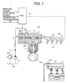
- Fig. 1 is a schematic diagram of a fuel supply system which is an embodiment of the present invention, showing the details of a variable-displacement single plunger pump uses as a high-pressure fuel pump.
- the part 101 is the whole high-pressure fuel pump.
- a pump 1 contains a suction passage 10, a discharge passage 11, and a compression chamber 12.
- the compression chamber 12 contains a sliding plunger 2 which is a pressurizing member.
- the plunger 2 is always pushed against a cam 100 by a spring so that the plunger in contact with the profile of the cam may go up and down as the cam 100 revolves.
- the cam 100 is mounted on the engine cam shaft 72 behind the engine cover 73.
- the suction passage 10 and the discharge passage 11 respectively contain a suction valve and a discharge valve. Each of these valves is pushed by a spring to flow fuel to a preset direction only. In other words, these valves work as non-return valves.
- the pump 1 holds a solenoid 200 having a connecting member 201 and a spring 202. As shown in Fig. 1, when the solenoid is off, the connecting member 201 is pushed by the spring 202 to. open the suction valve 5 as the pushing force of the spring 202 is greater than the pushing force of the spring in the suction valve 5.
- Fuel is transferred from a tank 50 to the fuel inlet of the pump 1 by a low-pressure pump 51, controlled by a pressure regulator to have a preset pressure, guided into the pump 51 through a low-pressure pipe 9, compressed by the pump 1, and pressure-fed from the fuel outlet to a common rail 53.
- the common rail 53 contains as may injectors 54 as the cylinders of the engine and a pressure sensor 56. The injectors inject fuel by signals from the controller 55.
- the plunger 2 reciprocates by the cam 100 which is driven by the engine cam shaft 72 and thus varies the volume in the compression chamber 12. If the suction valve 5 closes when the plunger is in a discharge stroke, the pressure in the compression chamber 12 goes up and opens the discharge valve 6. With this, fuel is pressure-fed to the common rail 53.
- the suction valve 5 automatically opens when the pressure in the compression chamber falls below the fuel inlet pressure, but closes by the operation of the solenoid 200.
- the solenoid 200 When the solenoid 200 is on (active), the solenoid produces an electromagnetic force greater than the pushing force of the spring 202 and pulls the connecting member 201 towards the solenoid. As the result, the connecting member goes away from the suction valve 5. While this status lasts, the suction valve works as an automatic valve which opens and closes in synchronism with the reciprocating motion of the plunger 2.
- the suction valve closes in the discharge stroke and fuel as much as the volumetric decrement of the compression chamber 12 is pressure-fed to the common rail 53 through the discharge valve. This makes the discharge rate of the pump maximum.
- the solenoid 200 when the solenoid 200 is off (inactive), the pushing force of the spring 202 pushes the connecting member to open the suction valve 5 and jeep the suction valve open.
- the pressure in the compression chamber 12 is approximately as low as the fuel inlet pressure also in the discharge stroke and the discharge valve 6 remains closed. Therefore, fuel as much as the volumetric decrement of the compression chamber 12 is fed back to the fuel inlet port through the suction valve 5. As the result, the discharge rate of the pump is 0.
- the controller calculates adequate discharge timing and controls the solenoid with the result.
- the high-pressure fuel pump 101 is a variable-volume pump using a single plunger whose discharge rate can be varied by the solenoid 202.
- a single plunger pump like this high-pressure fuel pump 101 is simple in configuration and facilitates variation of the volume. Further, it is less expensive and smaller than any other types of pumps, but its discharge is intermittent and the pressure in the common rail 53 greatly pulsates. This causes unevenness of fuel ejection rates.
- the fuel supply system for an inline 4-cylinder engine of Fig. 1 which is an embodiment of the present invention has a 2-peak cam 100 mounted on an engine cam shaft 72 so that the plunger 2 may make two reciprocations when the cam makes one revolution. With this, the plunger 2 makes one reciprocation while an injector 54 makes two cylinder injections. Further, the phase of the pulsating pressure in the common rail 53 can be in synchronism with the phase of fuel injection.
- the fuel pressure may go down or up according to the injection timing of an injector 54. In this case, unless the displacement of the plunger is in synchronism with the injection timing of the injector, the fuel pressure varies for each injection and the fuel injection rate may vary even when the valve opening time is constant.
- this embodiment drives the cam 100 by the engine cam shaft 72 which revolves at a rotational speed half as high as the engine speed, it is possible to drive a 1-peak cam by a crank shaft or the like that revolves at the same speed as the engine.
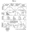
- Fig. 2 shows time-response waveforms of the plunger displacement, the pump flow rate, the injection rate of the injector, and the common rail pressure for one pump revolution (one cam revolution and two engine revolutions).
- the plunger makes two reciprocations and the engine makes two revolutions while the cam 100 makes one revolution.
- each cylinder makes one combustion while the engine makes two revolutions.
- four injectors respectively make one fuel injection while the cam 100 makes one revolution. This enables the pump to supply fuel for two injectors at every discharge.
- the pump makes one discharge for each one-cylinder injection of the injector.
- the inline 4-cylinder engine can have a 4-lobe cam which allows the plunger to make four reciprocations during one revolution of the cam.
- the plunger must make high reciprocations (250 reciprocations per second). Judging from the durability, size, and efficiency of the pump, it is hard to materialize it.
- the cam must have more lobes. This requires more reciprocations of the plunger and greater dimensions of the cam. Of course, it is sure that the mechanism cannot be materialized.
- the pump cavitation trouble becomes more serious as the plunger speed goes higher and the suction pressure goes lower.
- the pump cavitation will drastically reduce the pump efficiency and durability.
- additional apparatus such as a damper is required to prevent such as trouble. This increases the production cost and size of the engine.
- the fuel supply system of the present invention is designed so that the pump may make one discharge for two cylinder injections of injectors. This suppresses the reciprocating frequency of the plunger low and facilitates downsizing, cost reduction, and high efficiency of the pump. However, the unevenness of the injection rates of the injectors appears more conspicuously.
- the present invention provides a method of reducing the unevenness of fuel injection rates of cylinders by correcting the injection time width of each injector relative to a target injection time width of each injector which is calculated from the running status of the engine.
- the dot-dash line in the Time vs Pump Flow Rate graph indicates the flow rate of fuel when the pump makes a 100% discharge.
- the solid line indicates an actual discharge rate. It starts when the solenoid is turned on (not visible).
- the injector discharges only the required quantity of fuel. Therefore, the discharge volume Vp per discharge of the pump (hatched part) is equal to the total of injection volumes Va + Vb of the two injectors adjoining in the injection order.
- the common rail pressure (at the bottom of Fig. 2) cyclically repeats the steps of decreasing by ⁇ P relative to the mean pressure Pave when an injector injects, increasing by 2 ⁇ ⁇ P when the pump discharges, and decreasing again by ⁇ P down to Pave when the injector injects. So injectors #1 and #4 which inject in the discharge stroke inject less fuel because they inject while the common rail pressure is low and injectors #2 and #3 which inject in the suction stroke inject more fuel. This is the main cause of the unevenness the injection rates. Circles "o" in the graph means a common rail pressure during injection. This graph tells that the difference between mean injection pressures of injectors which are adjoining in the injection order is greatest.
- Fig. 2 shows an example of waveforms when the pump discharge period does not overlap with the injection period of injectors
- the waveforms will be more complicated when the pump discharge period overlaps with the injection period of injectors.
- the latter case has a tendency that the difference between the mean injection pressures of injectors goes smaller and the unevenness of the injection rates goes smaller, too.
- the unevenness of injection rates becomes greatest when the pressure difference becomes greatest.
- the present invention determines the maximum time width to correct the injection time width assuming that the pump discharge period for the maximum unevenness of injection rates does not overlap with the injection period of injectors.
- the injection time width Ta of injectors (#1 and #4 in the above description) which inject at a low injection pressure is made longer by a correction time width ⁇ T than the target injection time width Tref of the injector which is calculated from the running status of the engine.
- the injection time width Tb of injectors (#2 and #3 in the above description) which inject at a high injection pressure is made shorter by a correction time width ⁇ T than Tref. Ta and Tb are expressed as shown below.
- T a T ref + ⁇ T
- T b T ref + ⁇ T
- the injection rates Qa and Qb of injectors are approximately expressed with the mean injection pressure by the following: wherein "c” is a flow rate coefficient of an injector, "a” is an opening area, and " ⁇ ” is a fuel density.
- V a Q a ⁇ T a
- V b Q b ⁇ T b
- ⁇ Tmax is used instead of ⁇ T in Formula 8. This is because Fig. 2 show a mode in which the unevenness of injection rates becomes greatest and the correction time width ⁇ T becomes greatest in this mode. This ⁇ T is the maximum correction time width ⁇ Tmax.
- Pave and ⁇ P can be measured from pressure sensor signals while the engine is running and we can calculate and correct by sensor signals in a realtime manner. It is also possible to estimate Pave and ⁇ P in the following way:
- the present invention estimates ⁇ P from the target injection time width Tref of each injector by calculation.
- the mean pressure Pave can be a target pressure to keep a fuel pressure constant or an average of pressure sensor signal values. With this, the system can fetch ever-changing fuel pressures at high speed, detect Pave and ⁇ P without calculating them, and correct the injection time width.
- Fig. 2 shows an example of waveforms when the pump discharge period does not overlap with the injection period of injectors, it frequently occurs that these periods overlap and that the injector which injects fuel in the discharge stroke and the injector which injects in the suction stroke change strokes as the phase of the fuel injection of injectors varies a lot relative to the pump discharge.
- the phases of injections of injectors vary a lot as there are two fuel injection cases according to the loading status of the engine: injection in the suction stroke of the engine and injection in the compression stroke of the engine.
- some engines have a variable valve timing mechanism which varies the phase of the engine cam shaft by an actuator.
- the cam of the high-pressure fuel pump is driven by the engine cam shaft, the phase of the pump discharge also varies. Therefore, a method is required to flexibly correct such a great phase change in the pump discharge and the injection of injectors.
- Fig. 3 to Fig. 5 show examples of waveforms when the pump discharge period overlaps with the injection period of injectors.
- Fig. 3 shows examples of waveforms when the pump discharge period completely overlaps with the injection period of injectors.
- the pulse amplitude (2 ⁇ ⁇ P) of the common rail pressure in Fig. 3 is half of that in Fig. 2 ( ⁇ P). This is because the pressure increment due to a pump discharge is offset by injection of the injector. In this case, the difference between mean injection pressures of injectors adjoining in the injection order becomes very small and the unevenness of injection rates is also small enough to skip correction.
- Vps the quantity (volume) of fuel that the pump discharged before the injection start point of the injector whose injection period overlaps with the discharge period of the pump
- ⁇ Vps/Vp
- ⁇ represents at which timing of the pump discharge the injector injects fuel.
- the rise of the common rail pressure before the injector starts to inject fuel varies according to the value of " ⁇ .”
- the pressure rise indicated by a dot-dash line (which is 2 ⁇ ⁇ P in case the pump discharge rate does not overlap with the injection rate) is up to ⁇ P if " ⁇ " is 1/2 or ⁇ P/2 if " ⁇ " is up to 1/4.
- Fig. 3 shows waveforms when " ⁇ " is about 1/4.
- the difference between mean injection pressures of injectors adjoining in the injection order is very small and the unevenness of injection rates is also very small.
- Fig. 4 shows a waveform example when " ⁇ " is greater than 1/4, particularly, when " ⁇ " is 2/3.
- the mean injection pressure of an injector (#1 or #4 in the example) whose injection timing overlaps with the discharge timing of the pump is higher than the mean injection pressure of an injector (#2 or #3 in the example) whose injection timing does not overlap with the discharge timing and the injection rate Qa is greater than the injection rate Qb. Therefore, the injection time width Ta of the former injector must be shorter than the injection time width Tb of the latter injector. In this case, the difference between mean injection pressures becomes greater because the pressure ⁇ P' in Fig. 4 increases as " ⁇ " goes greater.
- Fig. 5 shows a waveform example when " ⁇ " is smaller than 1/4, particularly, when " ⁇ " is 0.
- the injection rate Qain is smaller than the injection rate Qb. Therefore, the injection time width Ta must be greater than Tb. If the phase of injection of an injector is shifted forward (relative to the phase in Fig. 5), the pressure ⁇ P" goes bigger and as the result the difference between mean injection pressures also becomes greater. However “ ⁇ " remains 0 as Vps is always 0.
- Fig. 7 shows a flow of correcting injection times in the fuel supply system of the present invention.
- the controller when starting a fuel injection rate control, the controller detects the running status of the engine from the acceleration opening, the crank angle, the engine speed, etc. and determines an injection start timing and a target injection time width Tref of each injector. Next the controller calculates a discharge start timing and a discharge time width of the pump from information such as the crank angle and the engine speed, checks the overlapping between the injection period of each injector and the discharge period of the pump, and determines ⁇ and ⁇ values. To get a correction time width, the controller calculates the maximum correction time width ⁇ Tmax from the target injection time width Tref and the mean fuel supply pressure Pave, and determines the correction time width ⁇ T from ⁇ Tmax, the ⁇ value, and the ⁇ value.
- the controller adds this correction time width ⁇ T to the target injection time width Tref or subtracts the correction time width ⁇ T from the target injection time width Tref, calculates injection time widths Ta and Tb of the injectors, and outputs the Ta and Tb values. With this, one control cycle is complete.
- the controller need not calculate any more injection time widths even when the engine has more cylinders (6, 8 or more cylinders). Unless the running status of the engine such as engine speed and acceleration opening makes a rapid change, the Ta values of injectors #1 and #4 in Fig. 4 need not be changed. Therefore, every one to some revolutions of the pump is enough as the operation period of one control cycle. This can greatly reduce the processing load of the controller.
- Fig. 8 shows the result of correction of unevenness of injection rates according to the above algorithm.
- the fuel supply system which is the embodiment of the present invention in Fig. 1 to Fig. 6 uses a high-pressure fuel pump which is constructed as shown in Fig. 1.
- this pump discharges fuel halfway in the discharge stroke without discharging from the start of the discharge stroke.
- the fuel supply system of the present system can also correct the unevenness of injection rates even when a variable-volume single-cylinder plunger of such a structure is used.
- Fig. 9 shows an example of this correction.
- Fig. 2 shows an example of waveforms when the pump discharge rate does not overlap with the injection rate of injectors.
- a great difference between Fig. 2 and Fig. 9 is the waveforms of pump discharge rates.
- the mean injection pressure of an injector (#1 or #4 in this example) which injects fuel just after the pump ends discharging is higher than the mean injection pressure of an injector (#2 or #3 in this example) which injects fuel after the injector #1 or #4. Therefore, the injection rate Qa is greater than the injection rate Qb.
- the unevenness of injection rates can be corrected by making the injection time width Ta smaller than Tb.
- the fuel supply system which is an embodiment of the present invention uses three parameters such as "target injection time width" of respective injectors, “mean fuel supply pressure,” and “overlapping” between the discharge period of the pump and the injection period of the injector to correct the injection time width.
- the controller can correct the injection time width without fetching ever-changing fuel pressures at high speed and reduce the unevenness of injection rates without a processing load.
- the fuel supply system can use this kind of information to correct injection time widths.
- the unevenness of injection rates can be reduced by extending the injection time width of an injector whose fuel supply pressure is lower, shortening the injection time width of an injector whose fuel supply pressure is higher and determining the increment or decrement of a correction time width according to the pressure difference between injectors.
- the fuel supply system of the present invention can suppress the unevenness of fuel injection rates of cylinders low.
- the ECU engine control unit
- the system can get the optimum combustion status and improve the power performance, fuel consumption ratio, and exhaust composition of the engine.
- the system can keep the injection rate unevenness at a low level even when the common rail has a small volume. This improves the ability of increasing and decreasing the fuel pressure of the engine. Consequently, this system can increase the compressing ability at the start of the engine and the responsibility to a change in the target fuel supply pressure at the transient running.
- the present invention aims at a fuel supply system comprising a variable-volume single plunger pump which is designed to make one discharge while two injections are made by the injectors and a controller which keeps the fuel supply pressure approximately constant by a variable volume control of the pump.
- a single plunger pump takes in and discharges fuel intermittently and makes the discharge pressure pulsate greatly. This causes the unevenness of injection rates of injectors.
- the present invention can eliminate such unevenness and provide a fuel supply system utilizing the merits of the pump such as low cost and energy saving.
- the fuel supply system of the present invention reduces the unevenness of fuel injection rates of cylinders by correcting the injection time width of respective injector relative to the target injection time width of the injector which is calculated from the running status of the engine.
- the fuel supply system of the present invention makes the injection time width of one of two fuel injection valves which inject during one discharge of the pump longer and that of the other injector shorter.
- the controller judges which injector is selected to make the injection time width longer or shorter from the injection timing of the injector in response to the discharge of the pump.
- the fuel pressure is higher than the mean pressure. Accordingly, the injection rate of an injector which injects at this time increases. After this injector injects fuel, the fuel pressure decreases. Accordingly, the fuel injection rate of the next injector becomes relatively less. Therefore, it is possible to reduce the unevenness of the injection rates by shortening the injection time width of the former injector and extending the injection time width of the latter injector.
- the controller detects an overlapping between the discharge period of the pump and the injection period of each injector.
- the controller shorten the injection time width of an injector which injects first after the pump ends one discharge and extends the injection time width of an injector which injects next.
- the controller extends the injection time width of an injector whose injection period overlaps with the discharge period of the pump and shortens the injection time width of the other injector.
- the controller shortens the injection time width of an injector whose injection period overlaps with the discharge period of the pump and extends the injection time width of the other injector. This is because the fuel pressure of an injector goes lower or higher than the fuel pressure of the other injector according to the timing of injection of the injector relative to the discharge of the pump. The turning point of this is located where the quantity of fuel that the pump discharges before the start of injection of an injector whose injection period overlaps with the discharge period of the pump is about 1/4 of the total quantity of fuel discharged.
- the unevenness of injection rates becomes greater as the difference between fuel injection pressures of two injectors goes greater. It is also dependent upon the magnitude of the mean fuel supply pressure. Further, the injection pressure difference has a tendency to go greater as the injection time width goes greater. As already explained above, the injection pressure difference varies according to the status of overlapping between the pump discharge period and the injection period. In a particular range, the injection pressure difference may be extremely small. Oppositely, when the periods do not overlap, the pressure difference and the unevenness of injection rates are greatest.
- the fuel supply system of the present invention determines the maximum correction time width when the discharge period does not overlap with the injection period from a target injection time width and a mean fuel supply pressure and makes the correction time width shorter than the maximum correction time width according to the overlapping between the discharge period and the injection period before outputting it. With this, the fuel supply system can reduce the unevenness of the injection rates in the wide running condition of the engine.
- the controller corrects the injection time width by three parameters of "target injection time width" of respective injectors, "mean fuel supply pressure,” and “overlapping” between the discharge period of the pump and the injection period of the injector to correct the injection time width.
- the mean fuel supply pressure need not be values from pressure sensors and can be a target value used to control the duel supply pressure constant. With this, the controller can correct the injection time width without fetching ever-changing fuel pressures at high speed and reduce the unevenness of injection rates without a processing load.
- the sufficient processing cycle of the controller is one to some revolutions of the pump.
- the system can correct the injection time width by using fuel pressure signals if they can be obtained at a comparative high speed. Concretely, it is possible to reduce the unevenness of injection rates by extending the injection time width of an injector whose fuel supply pressure is lower, shortening the injection time width of an injector whose fuel supply pressure is higher, and determining the correction time width according to the pressure difference of two injectors.
- the present invention can provide an engine fuel supply system which can reduce the unevenness of fuel injection rates of cylinders by correcting the injection command value for each injector without using information of ever-changing fuel pressure.
Abstract
Description
- This invention relates to a fuel supply system for a direct injection engine.
- Fuel supply systems have been disclosed in the prior art. For example, Japanese Application Patent Laid-open Publication No. Hei 11-294243 discloses a system for detecting ever-changing fuel pressures with sensors, calculating an actual fuel injection rate of each fuel injection valve (hereinafter called an injector) from data sent from the sensors, correcting the fuel injection command value of each injector so as to match the actual fuel injection rate with a target fuel injection rate, and thus evening off the fuel injection rates of the cylinders.
- Further, Japanese Application Patent Laid-open Publication No. Hei 11-36935 discloses a system for obtaining a target fuel injection rate by extending the fuel injection time of an injector when the actual fuel pressure is lower than a target fuel pressure and shortening the fuel injection time of an injector when the actual fuel pressure is higher than a target fuel pressure.
- A system disclosed in Japanese Application Patent Laid-open Publication No. Hei 11-294243 must fetch and calculate quick fuel pressure changes at a high speed and output resulting signals to injectors. This increases the load on the controller. Each injection of an injector is some milliseconds long and the fuel pressure changes greatly also in some milliseconds. However, the controller usually calculates in some milliseconds to 10 milliseconds. Therefore, it is difficult for the controller to precisely detect a quickly-changing fuel pressure. Further, it is assumed that an expensive controller is required to process such data at a high speed.
- Further, a system disclosed in Japanese Application Patent Laid-open Publication No. Hei 11-36935 uses only one pressure sensor to correct injection time periods of all injectors at a time from data of the sensor. This cannot reduce the unevenness of injection rates of the injectors.
- The primary object of the present invention is to provide a fuel supply system for an engine which can correct injection command values for respective injectors without using information about ever-changing fuel pressure and reduce the unevenness of injection rates of the injectors.
- The above object can be attained by a fuel supply system for a direct injection engine comprising a fuel pump which supplies fuel to injection valves by varying the volume by the reciprocal movement of a single-cylinder plunger, a driving mechanism which makes one reciprocal movement of said plunger while said injection valves inject fuel as much as two cylinders, and a controller which controls said fuel pump to adjust the fuel supply pressure, the injection start timing, and the injection time width of said fuel injection valve, wherein said controller works to make the injection time width of one of said two fuel injection valves longer and that of the other fuel injection valve shorter.
- The above object can also be attained by said fuel supply system, wherein said controller works to detect the start timing and time width of intermittent fuel discharge that said high pressure fuel pump makes in synchronism with said plunger and to correct the fuel injection time width of each fuel injection valve relative to a target injection time width according to a time period during which the discharge period of said high-pressure fuel pump and the injection period of said fuel injection valve overlap with each other, the target injection time width of each fuel injection valve calculated from the running status of said direct injection engine, and/or the mean value of said fuel supply pressures.
- The above object can also be attained by said fuel supply system, wherein said controller works to compare the phase of the discharge time period of said high pressure fuel pump by the phase of the injection time period of said fuel injection valve, determine whether to increase or decrease said fuel injection time width for correction, determine a maximum injection time width to be corrected from said target fuel injection time width and the mean value of said fuel supply pressures, subtracting the correction time period to be given to each fuel injection valve according to an overlapping between said discharge time period and said injection time period from said maximum fuel injection time width for correction, and/or output the result.
- The above object can also be attained by said fuel supply system, wherein said controller works to detect an overlapping between the discharge time period of
said high pressure fuel pump and the injection time period of said fuel injection valve, and if there is no overlapping between them, shorten the injection time period of a first fuel injection valve that first injects fuel after one discharge by said high pressure fuel pump is completed and extend the injection time period of a second fuel injection valve that injects fuel next, if there is an overlapping and if the high pressure fuel pump supplies about one fourth or less of the whole fuel discharge quantity by the injection start timing of the fuel injection valve whose injection time period overlaps the discharge time period, extend the injection time period of the fuel injection valve whose injection time period overlaps the discharge time period and shorten the injection time period of the other fuel injection valve, or if the high pressure fuel pump supplies about one fourth or more of the whole fuel discharge quantity, shorten the injection time period of the fuel injection valve whose injection time period overlaps the discharge time period and extend the injection time period of the other fuel injection valve. - The above object can also be attained by said fuel supply system, wherein said controller works to detect a pressure of supplying fuel to said fuel injection valve, extend the injection time width of an fuel injection valve whose fuel supply pressure is lower, and shorten the injection time width of an fuel injection valve whose fuel supply pressure is higher.
-
- Fig. 1 is a schematic representation of a fuel supply system of the present invention;
- Fig. 2 is an example of waveforms for correction of injection time by the fuel supply system of the present invention;
- Fig. 3 is an example of waveforms for correction of injection time by the fuel supply system of the present invention;
- Fig. 4 is an example of waveforms for correction of injection time by the fuel supply system of the present invention;
- Fig. 5 is an example of waveforms for correction of injection time by the fuel supply system of the present invention;
- Fig. 6 shows behaviors of waveforms when the injection phases of injections in the fuel supply system of the present invention are shifted gradually;
- Fig. 7 is a flowchart of correcting the injection time by the fuel supply system of the present invention;
- Fig. 8 shows the effect of correction of the injection time by the fuel supply system of the present invention; and
- Fig. 9 shows an example of correction of the injection time in a system having a high-pressure fuel pump of the other type.
-
- The object of the present invention is to provide a fuel supply system comprising a variable-volume single plunger pump which can make a single discharge while injectors for two cylinders inject fuel and a controller which controls the variable volume of the pump to keep the fuel supply pressure approximately constant.
- Usually the single plunger pump intermittently takes in and out fuel. This causes the discharge pressure to pulsate greatly and makes uneven injection rates of the injectors. The present invention can solve this problem and makes the most of features of the pump such as low cost and energy saving.
- The embodiments of the present invention will be explained in connection with the accompanying drawings.
- Fig. 1 is a schematic diagram of a fuel supply system which is an embodiment of the present invention, showing the details of a variable-displacement single plunger pump uses as a high-pressure fuel pump.
- Referring to Fig. 1, the part 101 is the whole high-pressure fuel pump. A pump 1 contains a suction passage 10, a discharge passage 11, and a compression chamber 12. The compression chamber 12 contains a sliding plunger 2 which is a pressurizing member. The plunger 2 is always pushed against a cam 100 by a spring so that the plunger in contact with the profile of the cam may go up and down as the cam 100 revolves. The cam 100 is mounted on the engine cam shaft 72 behind the engine cover 73. The suction passage 10 and the discharge passage 11 respectively contain a suction valve and a discharge valve. Each of these valves is pushed by a spring to flow fuel to a preset direction only. In other words, these valves work as non-return valves. The pump 1 holds a solenoid 200 having a connecting member 201 and a spring 202. As shown in Fig. 1, when the solenoid is off, the connecting member 201 is pushed by the spring 202 to. open the suction valve 5 as the pushing force of the spring 202 is greater than the pushing force of the spring in the suction valve 5.
- Fuel is transferred from a tank 50 to the fuel inlet of the pump 1 by a low-pressure pump 51, controlled by a pressure regulator to have a preset pressure, guided into the pump 51 through a low-pressure pipe 9, compressed by the pump 1, and pressure-fed from the fuel outlet to a common rail 53. The common rail 53 contains as may injectors 54 as the cylinders of the engine and a pressure sensor 56. The injectors inject fuel by signals from the controller 55.
- Below will be explained the operation of the high-pressure fuel pump of the above configuration..
- As explained above, the plunger 2 reciprocates by the cam 100 which is driven by the engine cam shaft 72 and thus varies the volume in the compression chamber 12. If the suction valve 5 closes when the plunger is in a discharge stroke, the pressure in the compression chamber 12 goes up and opens the discharge valve 6. With this, fuel is pressure-fed to the common rail 53.
- The suction valve 5 automatically opens when the pressure in the compression chamber falls below the fuel inlet pressure, but closes by the operation of the solenoid 200.
- When the solenoid 200 is on (active), the solenoid produces an electromagnetic force greater than the pushing force of the spring 202 and pulls the connecting member 201 towards the solenoid. As the result, the connecting member goes away from the suction valve 5. While this status lasts, the suction valve works as an automatic valve which opens and closes in synchronism with the reciprocating motion of the plunger 2.
- In other words, the suction valve closes in the discharge stroke and fuel as much as the volumetric decrement of the compression chamber 12 is pressure-fed to the common rail 53 through the discharge valve. This makes the discharge rate of the pump maximum.
- Contrarily, when the solenoid 200 is off (inactive), the pushing force of the spring 202 pushes the connecting member to open the suction valve 5 and jeep the suction valve open. In this status, the pressure in the compression chamber 12 is approximately as low as the fuel inlet pressure also in the discharge stroke and the discharge valve 6 remains closed. Therefore, fuel as much as the volumetric decrement of the compression chamber 12 is fed back to the fuel inlet port through the suction valve 5. As the result, the discharge rate of the pump is 0.
- When the solenoid 200 is turned on halfway in the discharge stroke, pressure-feeding of fuel to the common rail 53 starts. Once it starts, the pressure in the compression chamber 12 goes up and the suction valve 5 remains closed even when the solenoid is turned off thereafter. The suction valve 5 opens in synchronism with the start of the suction stroke after the discharge stroke is complete. It is possible to control the fuel discharge rate in the range of 0% to 100% by the "on" timing of the solenoid 20.
- To keep the pressure in the common rail 53 approximately constant, the controller calculates adequate discharge timing and controls the solenoid with the result.
- In the above description, the high-pressure fuel pump 101 is a variable-volume pump using a single plunger whose discharge rate can be varied by the solenoid 202. A single plunger pump like this high-pressure fuel pump 101 is simple in configuration and facilitates variation of the volume. Further, it is less expensive and smaller than any other types of pumps, but its discharge is intermittent and the pressure in the common rail 53 greatly pulsates. This causes unevenness of fuel ejection rates.
- To solve this problem, the fuel supply system for an inline 4-cylinder engine of Fig. 1 which is an embodiment of the present invention has a 2-peak cam 100 mounted on an engine cam shaft 72 so that the plunger 2 may make two reciprocations when the cam makes one revolution. With this, the plunger 2 makes one reciprocation while an injector 54 makes two cylinder injections. Further, the phase of the pulsating pressure in the common rail 53 can be in synchronism with the phase of fuel injection.
- If the pulsating pressure is great, the fuel pressure may go down or up according to the injection timing of an injector 54. In this case, unless the displacement of the plunger is in synchronism with the injection timing of the injector, the fuel pressure varies for each injection and the fuel injection rate may vary even when the valve opening time is constant.
- Although this embodiment drives the cam 100 by the engine cam shaft 72 which revolves at a rotational speed half as high as the engine speed, it is possible to drive a 1-peak cam by a crank shaft or the like that revolves at the same speed as the engine.
- Fig. 2 shows time-response waveforms of the plunger displacement, the pump flow rate, the injection rate of the injector, and the common rail pressure for one pump revolution (one cam revolution and two engine revolutions).
- In Fig. 2, the plunger makes two reciprocations and the engine makes two revolutions while the cam 100 makes one revolution. As for a usual 4-cycle engine, each cylinder makes one combustion while the engine makes two revolutions. In other words, four injectors respectively make one fuel injection while the cam 100 makes one revolution. This enables the pump to supply fuel for two injectors at every discharge.
- For easy comprehension of this mechanism, let's assume the injectors of an inline 4-cylinder engine are assigned numbers as shown in Fig. 1. The injectors #1 to #4 inject fuel in the order of #1, #3, #4, and #2 (where "#" means "Number") as shown in Fig. 2. This mechanism can synchronize the plunger displacement and the injection timing of injectors with each other, but this mechanism classifies injectors into two:
- injectors which inject in the suction stroke and
- injectors which inject in the delivery stroke of the pump (to be explained later). This still holds a problem that the injection rates of the injectors are uneven.
-
- To avoid this, it is ideal that the pump makes one discharge for each one-cylinder injection of the injector.
- For example, the inline 4-cylinder engine can have a 4-lobe cam which allows the plunger to make four reciprocations during one revolution of the cam. However, for an engine whose maximum speed is 8,000 revolutions per minute, the plunger must make high reciprocations (250 reciprocations per second). Judging from the durability, size, and efficiency of the pump, it is hard to materialize it. Further, as the engine has more cylinders (6 cylinders, 8 cylinders or more), the cam must have more lobes. This requires more reciprocations of the plunger and greater dimensions of the cam. Of course, it is sure that the mechanism cannot be materialized.
- Particularly, the pump cavitation trouble becomes more serious as the plunger speed goes higher and the suction pressure goes lower. The pump cavitation will drastically reduce the pump efficiency and durability. Further, additional apparatus such as a damper is required to prevent such as trouble. This increases the production cost and size of the engine.
- Judging from the above, the fuel supply system of the present invention is designed so that the pump may make one discharge for two cylinder injections of injectors. This suppresses the reciprocating frequency of the plunger low and facilitates downsizing, cost reduction, and high efficiency of the pump. However, the unevenness of the injection rates of the injectors appears more conspicuously.
- So, the present invention provides a method of reducing the unevenness of fuel injection rates of cylinders by correcting the injection time width of each injector relative to a target injection time width of each injector which is calculated from the running status of the engine.
- Referring to Fig. 2, below will be explained in detail the mechanism of generating unevenness of injection rates.
- In Fig. 2, the dot-dash line in the Time vs Pump Flow Rate graph indicates the flow rate of fuel when the pump makes a 100% discharge. The solid line indicates an actual discharge rate. It starts when the solenoid is turned on (not visible). The injector discharges only the required quantity of fuel. Therefore, the discharge volume Vp per discharge of the pump (hatched part) is equal to the total of injection volumes Va + Vb of the two injectors adjoining in the injection order.
- The common rail pressure (at the bottom of Fig. 2) cyclically repeats the steps of decreasing by ΔP relative to the mean pressure Pave when an injector injects, increasing by 2 × ΔP when the pump discharges, and decreasing again by ΔP down to Pave when the injector injects. So injectors #1 and #4 which inject in the discharge stroke inject less fuel because they inject while the common rail pressure is low and injectors #2 and #3 which inject in the suction stroke inject more fuel. This is the main cause of the unevenness the injection rates. Circles "o" in the graph means a common rail pressure during injection. This graph tells that the difference between mean injection pressures of injectors which are adjoining in the injection order is greatest.
- Although Fig. 2 shows an example of waveforms when the pump discharge period does not overlap with the injection period of injectors, the waveforms will be more complicated when the pump discharge period overlaps with the injection period of injectors. The latter case has a tendency that the difference between the mean injection pressures of injectors goes smaller and the unevenness of the injection rates goes smaller, too. As shown in Fig. 2, the unevenness of injection rates becomes greatest when the pressure difference becomes greatest.
- The present invention determines the maximum time width to correct the injection time width assuming that the pump discharge period for the maximum unevenness of injection rates does not overlap with the injection period of injectors.
- Below will be explained how the unevenness of the injection rates is corrected.
- In the present invention, the injection time width Ta of injectors (#1 and #4 in the above description) which inject at a low injection pressure is made longer by a correction time width ΔT than the target injection time width Tref of the injector which is calculated from the running status of the engine. Contrarily, the injection time width Tb of injectors (#2 and #3 in the above description) which inject at a high injection pressure is made shorter by a correction time width ΔT than Tref. Ta and Tb are expressed as shown below.
- The injection rates Qa and Qb of injectors are approximately expressed with the mean injection pressure by the following:
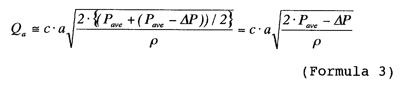
 wherein "c" is a flow rate coefficient of an injector, "a" is an opening area, and "ρ" is a fuel density.
- The volumes Va and Vb of fuel injected at each injection are expressed by the following:
- As the injection rates become even when Va = Vb, so we calculate a correction time width ΔT to make Va equal to Vb. For Va = Vb, we obtain
- The meaning of this relationship is quite obvious from the Injection Rate vs Time graph of Fig. 2. Namely, as there is a difference between mean injection pressures, Qa is less than Qb. Therefore, we can make Va equal to Vb (the hatched areas) by making Ta greater than Tb.
- By substituting Formula 1 to Formula 4 for Formula 7 and solving for ΔT, we obtain the following:
- ΔTmax is used instead of ΔT in Formula 8. This is because Fig. 2 show a mode in which the unevenness of injection rates becomes greatest and the correction time width ΔT becomes greatest in this mode. This ΔT is the maximum correction time width ΔTmax.
- From Formula 8, we know that we can calculate the maximum correction time width ΔTmax when we get a mean pressure Pave and a half amplitude ΔP of the pressure pulsation. Pave and ΔP can be measured from pressure sensor signals while the engine is running and we can calculate and correct by sensor signals in a realtime manner. It is also possible to estimate Pave and ΔP in the following way:
- Further, it is necessary to shorten the sampling period down to about 1ms to detect a pressure difference ΔP accurately as the pressure changes very quickly. A usual controller is not enough to detect ΔP accurately because its sampling and processing cycle is a few ms to about 10 ms. So an expensive faster controller is required to detect such ΔP or it is required to fetch data for a long time, extract maximum and minimum points from a lot of data points, and calculate ΔP to increase the accuracy of ΔP. However, this extends a control period and reduces the ability to follow up changes in the operating conditions of the engine.
- Therefore, the present invention estimates ΔP from the target injection time width Tref of each injector by calculation. Here, as the coefficient B of bulk modulus of fuel and the volume Vc of the common rail are known, we can calculate ΔP from a compression formula if we get the volume of injection of each injector. Assuming that the mean injection volume per injection is Vave (= (Va + Vb)/2), we obtain ΔP as follows:
- The mean pressure Pave can be a target pressure to keep a fuel pressure constant or an average of pressure sensor signal values. With this, the system can fetch ever-changing fuel pressures at high speed, detect Pave and ΔP without calculating them, and correct the injection time width.
- Next below will be explained a method of correcting the injection time width when the discharge time period and the injection time period overlap with each other.
- Although Fig. 2 shows an example of waveforms when the pump discharge period does not overlap with the injection period of injectors, it frequently occurs that these periods overlap and that the injector which injects fuel in the discharge stroke and the injector which injects in the suction stroke change strokes as the phase of the fuel injection of injectors varies a lot relative to the pump discharge. Particularly, as for a direct injection engine, the phases of injections of injectors vary a lot as there are two fuel injection cases according to the loading status of the engine: injection in the suction stroke of the engine and injection in the compression stroke of the engine.
- Further, some engines have a variable valve timing mechanism which varies the phase of the engine cam shaft by an actuator. When the cam of the high-pressure fuel pump is driven by the engine cam shaft, the phase of the pump discharge also varies. Therefore, a method is required to flexibly correct such a great phase change in the pump discharge and the injection of injectors.
- Fig. 3 to Fig. 5 show examples of waveforms when the pump discharge period overlaps with the injection period of injectors.
- Fig. 3 shows examples of waveforms when the pump discharge period completely overlaps with the injection period of injectors. In comparison to Fig. 2, we can see that the pulse amplitude (2 × ΔP) of the common rail pressure in Fig. 3 is half of that in Fig. 2 (ΔP). This is because the pressure increment due to a pump discharge is offset by injection of the injector. In this case, the difference between mean injection pressures of injectors adjoining in the injection order becomes very small and the unevenness of injection rates is also small enough to skip correction.
- Here, we define Vps as the quantity (volume) of fuel that the pump discharged before the injection start point of the injector whose injection period overlaps with the discharge period of the pump and α (= Vps/Vp) as a ratio of Vps to the total discharge volume per discharge. In other words, α represents at which timing of the pump discharge the injector injects fuel. The rise of the common rail pressure before the injector starts to inject fuel varies according to the value of "α." As shown in Fig. 3, the pressure rise indicated by a dot-dash line (which is 2 × ΔP in case the pump discharge rate does not overlap with the injection rate) is up to ΔP if "α" is 1/2 or ΔP/2 if "α" is up to 1/4.
- Fig. 3 shows waveforms when "α" is about 1/4. In this case, the difference between mean injection pressures of injectors adjoining in the injection order is very small and the unevenness of injection rates is also very small.
- Fig. 4 shows a waveform example when "α" is greater than 1/4, particularly, when "α" is 2/3. In this case, the mean injection pressure of an injector (#1 or #4 in the example) whose injection timing overlaps with the discharge timing of the pump is higher than the mean injection pressure of an injector (#2 or #3 in the example) whose injection timing does not overlap with the discharge timing and the injection rate Qa is greater than the injection rate Qb. Therefore, the injection time width Ta of the former injector must be shorter than the injection time width Tb of the latter injector. In this case, the difference between mean injection pressures becomes greater because the pressure ΔP' in Fig. 4 increases as "α" goes greater.
- Fig. 5 shows a waveform example when "α" is smaller than 1/4, particularly, when "α" is 0. In this case opposite to the case of Fig. 4, the injection rate Qain is smaller than the injection rate Qb. Therefore, the injection time width Ta must be greater than Tb. If the phase of injection of an injector is shifted forward (relative to the phase in Fig. 5), the pressure ΔP" goes bigger and as the result the difference between mean injection pressures also becomes greater. However "α" remains 0 as Vps is always 0.
- In other words, single "α" is not enough to express the magnitude of the injection pressure difference. Here, we define Vis as the quantity (volume) of fuel that the pump discharged before the injection start point of the injector whose injection period overlaps with the discharge period of the pump (as shown in Fig. 5) and β (= Vis/Vp) as a ratio of Vis to the discharge volume Vp. The fall of the common rail pressure before the pump starts to discharge fuel varies according to the value of "β."
- So by using α and β in combination, it is possible to express the magnitude of the injection pressures of two adjoining injectors under a wide condition. This will be explained below referring to Fig. 6.
- Fig. 6 shows transitions of common rail pressure, α value, β value, and correction time width ΔT when the phases of injection rates are shifted gradually. Note that the horizontal axes are not time bases. At the left end of each graph, the pump discharge rate does not overlap with the injection rate. As you go to the right, the injection rate phase shifted backwards and the pump discharge rate starts to overlap with the injection rate. The injection pressure difference between two adjoining injectors (indicated by arrows) is the greatest in the leftmost end of the graph, gradually decreases as you go to the right, and reaches 0 near the center (α = 1/4). Further as you go to the right (when α > 1/4), the injection pressure difference goes negative (or the injector pressures are reversed) and the pressure difference gradually goes greater. The α and β values behave as shown in Fig. 6 and are 0 at the same time. By using α and β in combination, it is possible to digitally express the change of the injection pressure difference to the injection phase change. Consequently, the correction time width ΔT can be expressed as a function of α and β as shown in Fig. 6.
- Formula 11 represents a line connecting a point of the maximum correction time width ΔTmax when the pump discharge rate does not overlap with the injection rate and a point of a correction time width 0 when the injection pressure difference at α = 1/4 is about 0 and is a function of α and β. With two parameters α and β, this function can determine the magnitude and direction of the correction time width at the same time.
- Fig. 7 shows a flow of correcting injection times in the fuel supply system of the present invention.
- In Fig. 7, when starting a fuel injection rate control, the controller detects the running status of the engine from the acceleration opening, the crank angle, the engine speed, etc. and determines an injection start timing and a target injection time width Tref of each injector. Next the controller calculates a discharge start timing and a discharge time width of the pump from information such as the crank angle and the engine speed, checks the overlapping between the injection period of each injector and the discharge period of the pump, and determines α and β values. To get a correction time width, the controller calculates the maximum correction time width ΔTmax from the target injection time width Tref and the mean fuel supply pressure Pave, and determines the correction time width ΔT from ΔTmax, the α value, and the β value. Finally, the controller adds this correction time width ΔT to the target injection time width Tref or subtracts the correction time width ΔT from the target injection time width Tref, calculates injection time widths Ta and Tb of the injectors, and outputs the Ta and Tb values. With this, one control cycle is complete.
- As the fuel supply system in accordance with the present invention offers only two injection time widths one of which is for half of all injectors and the other for the remaining half of the injectors, the controller need not calculate any more injection time widths even when the engine has more cylinders (6, 8 or more cylinders). Unless the running status of the engine such as engine speed and acceleration opening makes a rapid change, the Ta values of injectors #1 and #4 in Fig. 4 need not be changed. Therefore, every one to some revolutions of the pump is enough as the operation period of one control cycle. This can greatly reduce the processing load of the controller.
- Fig. 8 shows the result of correction of unevenness of injection rates according to the above algorithm.
- For a representative Tref value of 3.5 mm, we can get ΔT of 0.03 ms. In this case, the pulse widths Ta and Tb after correction are
- As shown in Fig. 8, we have reconfirmed by numeric simulation or the like that this correction can greatly reduce the unevenness of injection rates.
- The fuel supply system which is the embodiment of the present invention in Fig. 1 to Fig. 6 uses a high-pressure fuel pump which is constructed as shown in Fig. 1. For variable volume control, this pump discharges fuel halfway in the discharge stroke without discharging from the start of the discharge stroke. There also exist pumps that discharge fuel from the start of the discharge stroke and stop discharging halfway in the discharge stroke for variable volume control. The fuel supply system of the present system can also correct the unevenness of injection rates even when a variable-volume single-cylinder plunger of such a structure is used. Fig. 9 shows an example of this correction.
- Fig. 2 shows an example of waveforms when the pump discharge rate does not overlap with the injection rate of injectors. A great difference between Fig. 2 and Fig. 9 is the waveforms of pump discharge rates. Similarly to Fig. 2, the mean injection pressure of an injector (#1 or #4 in this example) which injects fuel just after the pump ends discharging is higher than the mean injection pressure of an injector (#2 or #3 in this example) which injects fuel after the injector #1 or #4. Therefore, the injection rate Qa is greater than the injection rate Qb. In this case, the unevenness of injection rates can be corrected by making the injection time width Ta smaller than Tb. We can also get a correction time width by calculating the maximum correction time width ΔTmax from the target injection time width Tref and the mean fuel supply pressure Pave, and calculating the correction time width ΔT from ΔTmax, the α value, and the β value. It is apparent that the similar correction can be done according to the algorithm of the present invention although α and β must be defined a little differently.
- Although the above embodiment is so designed that the controller may always correct injection time widths, the correction can be omitted when the target injection time width Tref is short enough because the half amplitude ΔP of the pulsating pressure goes smaller and the unevenness of injection rates is small enough from the start. This can reduce the processing load of the controller. Further, there is almost no difference between mean injection pressures of two injectors adjoining in the injection order when the α value is near 1/4 and the unevenness of injection rates is small enough to omit the correction of injection time widths. Further, when α is near 1/4, it is difficult to judge which injector has a higher fuel injection pressure because it is dependent upon the running condition of the engine. If a wrong correction is made, the injection rates may have more unevenness. Therefore, this omission of correction at α = about 1/4 can not only suppress the unevenness of injection rates but also reduce the processing load of the controller.
- As explained above, the fuel supply system which is an embodiment of the present invention uses three parameters such as "target injection time width" of respective injectors, "mean fuel supply pressure," and "overlapping" between the discharge period of the pump and the injection period of the injector to correct the injection time width. With this, the controller can correct the injection time width without fetching ever-changing fuel pressures at high speed and reduce the unevenness of injection rates without a processing load.
- Contrarily, if fuel pressure signals can be obtained at a high speed, the fuel supply system can use this kind of information to correct injection time widths. To be concrete, the unevenness of injection rates can be reduced by extending the injection time width of an injector whose fuel supply pressure is lower, shortening the injection time width of an injector whose fuel supply pressure is higher and determining the increment or decrement of a correction time width according to the pressure difference between injectors.
- As explained above, the fuel supply system of the present invention can suppress the unevenness of fuel injection rates of cylinders low. With this, the ECU (engine control unit) can reduce correction of the air-fuel ratio and perform stable engine control. Further, as the fuel supply system of the present invention can accurately control the fuel injection rate that the engine requires, the system can get the optimum combustion status and improve the power performance, fuel consumption ratio, and exhaust composition of the engine. Further the system can keep the injection rate unevenness at a low level even when the common rail has a small volume. This improves the ability of increasing and decreasing the fuel pressure of the engine. Consequently, this system can increase the compressing ability at the start of the engine and the responsibility to a change in the target fuel supply pressure at the transient running.
- Particularly, the present invention aims at a fuel supply system comprising a variable-volume single plunger pump which is designed to make one discharge while two injections are made by the injectors and a controller which keeps the fuel supply pressure approximately constant by a variable volume control of the pump.
- Generally, a single plunger pump takes in and discharges fuel intermittently and makes the discharge pressure pulsate greatly. This causes the unevenness of injection rates of injectors. However, the present invention can eliminate such unevenness and provide a fuel supply system utilizing the merits of the pump such as low cost and energy saving.
- In summary, the fuel supply system of the present invention reduces the unevenness of fuel injection rates of cylinders by correcting the injection time width of respective injector relative to the target injection time width of the injector which is calculated from the running status of the engine. Basically, the fuel supply system of the present invention makes the injection time width of one of two fuel injection valves which inject during one discharge of the pump longer and that of the other injector shorter. In this case, the controller judges which injector is selected to make the injection time width longer or shorter from the injection timing of the injector in response to the discharge of the pump.
- For example, immediately after the pump completes one discharge, the fuel pressure is higher than the mean pressure. Accordingly, the injection rate of an injector which injects at this time increases. After this injector injects fuel, the fuel pressure decreases. Accordingly, the fuel injection rate of the next injector becomes relatively less. Therefore, it is possible to reduce the unevenness of the injection rates by shortening the injection time width of the former injector and extending the injection time width of the latter injector.
- To be concrete, the controller detects an overlapping between the discharge period of the pump and the injection period of each injector. When the periods do not overlap with each other, the controller shorten the injection time width of an injector which injects first after the pump ends one discharge and extends the injection time width of an injector which injects next. When the periods overlap with each other and the quantity of fuel that the pump discharges before the start of injection of an injector whose injection period overlaps with the discharge period of the pump is about 1/4 or less of the total quantity of fuel discharged, the controller extends the injection time width of an injector whose injection period overlaps with the discharge period of the pump and shortens the injection time width of the other injector. When the quantity of fuel that the pump discharges before the start of injection of an injector whose injection period overlaps with the discharge period of the pump is about 1/4 or more of the total quantity of fuel discharged, the controller shortens the injection time width of an injector whose injection period overlaps with the discharge period of the pump and extends the injection time width of the other injector. This is because the fuel pressure of an injector goes lower or higher than the fuel pressure of the other injector according to the timing of injection of the injector relative to the discharge of the pump. The turning point of this is located where the quantity of fuel that the pump discharges before the start of injection of an injector whose injection period overlaps with the discharge period of the pump is about 1/4 of the total quantity of fuel discharged.
- As for determination of a correction time width, the unevenness of injection rates becomes greater as the difference between fuel injection pressures of two injectors goes greater. It is also dependent upon the magnitude of the mean fuel supply pressure. Further, the injection pressure difference has a tendency to go greater as the injection time width goes greater. As already explained above, the injection pressure difference varies according to the status of overlapping between the pump discharge period and the injection period. In a particular range, the injection pressure difference may be extremely small. Oppositely, when the periods do not overlap, the pressure difference and the unevenness of injection rates are greatest.
- The fuel supply system of the present invention determines the maximum correction time width when the discharge period does not overlap with the injection period from a target injection time width and a mean fuel supply pressure and makes the correction time width shorter than the maximum correction time width according to the overlapping between the discharge period and the injection period before outputting it. With this, the fuel supply system can reduce the unevenness of the injection rates in the wide running condition of the engine.
- As explained above, the controller corrects the injection time width by three parameters of "target injection time width" of respective injectors, "mean fuel supply pressure," and "overlapping" between the discharge period of the pump and the injection period of the injector to correct the injection time width. The mean fuel supply pressure need not be values from pressure sensors and can be a target value used to control the duel supply pressure constant. With this, the controller can correct the injection time width without fetching ever-changing fuel pressures at high speed and reduce the unevenness of injection rates without a processing load. In accordance with the fuel supply system of the present invention, the sufficient processing cycle of the controller is one to some revolutions of the pump.
- The system can correct the injection time width by using fuel pressure signals if they can be obtained at a comparative high speed. Concretely, it is possible to reduce the unevenness of injection rates by extending the injection time width of an injector whose fuel supply pressure is lower, shortening the injection time width of an injector whose fuel supply pressure is higher, and determining the correction time width according to the pressure difference of two injectors.
- The present invention can provide an engine fuel supply system which can reduce the unevenness of fuel injection rates of cylinders by correcting the injection command value for each injector without using information of ever-changing fuel pressure.
Claims (5)
- A fuel supply system for a direct injection engine comprising a fuel pump (101) which supplies fuel to injection valves (54) by varying the volume by the reciprocal movement of a single-cylinder plunger (2), a driving mechanism which makes one reciprocal movement of said plunger (2) while said injection valves (54) inject fuel as much as two cylinders, and a controller (55) which controls said fuel pump to adjust the fuel supply pressure, the injection start timing, and the injection time width of said fuel injection valve (54), wherein said controller (55) works to make the injection time width of one of said two fuel injection valves (54) longer and that of the other fuel injection valve (54) shorter.
- A fuel supply system in accordance with claim 1, wherein said controller (55) works to detect the start timing and time width of intermittent fuel discharge that said high pressure fuel pump (101) makes in synchronism with said plunger (2) and to correct the fuel injection time width of each fuel injection valve (54) relative to a target injection time width according to a time period during which the discharge period of said high-pressure fuel pump (101) and the injection period of said fuel injection valve (54) overlap with each other, the target injection time width of each fuel injection valve (54) calculated from the running status of said direct injection engine, and the mean value of said fuel supply pressures.
- A fuel supply system in accordance with claim 1 or 2, wherein said controller (55) works to compare the phase of the discharge time period of said high pressure fuel pump (101) by the phase of the injection time period of said fuel injection valve (54), determine whether to increase or decrease said fuel injection time width for correction, determine a maximum injection time width to be corrected from said target fuel injection time width and the mean value of said fuel supply pressures, subtracting the correction time period to be given to each fuel injection valve (54) according to an overlapping between said discharge time period and said injection time period from said maximum fuel injection time width for correction, and output the result.
- A fuel supply system in accordance with any of claim 1 to claim 3, wherein said controller (55) works to detect an overlapping between the discharge time period of said high pressure fuel pump (101) and the injection time period of said fuel injection valve (54), and
if there is no overlapping between them, shorten the injection time period of a first fuel injection valve (54) that first injects fuel after one discharge by said high pressure fuel pump (101) is completed and extend the injection time period of a second fuel injection valve (54) that injects fuel next,
if there is an overlapping and if the high pressure fuel pump (101) supplies about one fourth or less of the whole fuel discharge quantity by the injection start timing of the fuel injection valve (54) whose injection time period overlaps the discharge time period, extend the injection time period of the fuel injection valve (54) whose injection time period overlaps the discharge time period and shorten the injection time period of the other fuel injection valve (54), or
if the high pressure fuel pump (101) supplies about one fourth or more of the whole fuel discharge quantity, shorten the injection time period of the fuel injection valve (54) whose injection time period overlaps the discharge time period and extend the injection time period of the other fuel injection valve (54). - A fuel supply system in accordance with claim 1, wherein said controller (55) works to detect a pressure of supplying fuel to said fuel injection valve (54), extend the injection time width of an fuel injection valve (54) whose fuel supply pressure is lower, and shorten the injection time width of an fuel injection valve (54) whose fuel supply pressure is higher.
Applications Claiming Priority (2)
| Application Number | Priority Date | Filing Date | Title |
|---|---|---|---|
| JP2001073282A JP4627603B2 (en) | 2001-03-15 | 2001-03-15 | Fuel supply device |
| JP2001073282 | 2001-03-15 |
Publications (3)
| Publication Number | Publication Date |
|---|---|
| EP1241338A2 true EP1241338A2 (en) | 2002-09-18 |
| EP1241338A3 EP1241338A3 (en) | 2004-09-22 |
| EP1241338B1 EP1241338B1 (en) | 2008-04-16 |
Family
ID=18930733
Family Applications (1)
| Application Number | Title | Priority Date | Filing Date |
|---|---|---|---|
| EP02001176A Expired - Lifetime EP1241338B1 (en) | 2001-03-15 | 2002-01-28 | Fuel supply system |
Country Status (4)
| Country | Link |
|---|---|
| US (1) | US6725837B2 (en) |
| EP (1) | EP1241338B1 (en) |
| JP (1) | JP4627603B2 (en) |
| DE (1) | DE60226091T2 (en) |
Cited By (10)
| Publication number | Priority date | Publication date | Assignee | Title |
|---|---|---|---|---|
| EP1281860A2 (en) | 2001-08-02 | 2003-02-05 | Siemens Aktiengesellschaft | Injection System for an Internal Combustion Engine and Method for Operating the Same |
| EP1296061A2 (en) * | 2001-09-21 | 2003-03-26 | Hitachi, Ltd. | High pressure fuel pump |
| EP1536137A1 (en) * | 2003-11-25 | 2005-06-01 | Magneti Marelli Powertrain S.p.A. | Fuel pump for an internal combustion engine |
| EP1598548A1 (en) * | 2004-05-20 | 2005-11-23 | Magneti Marelli Powertrain S.p.A. | Method and system for the direct injection of fuel into an internal combustion engine |
| EP1598549A1 (en) * | 2004-05-20 | 2005-11-23 | Magneti Marelli Powertrain S.p.A. | Method for the direct injection of fuel into an internal combustion engine |
| EP1657434A1 (en) * | 2004-11-12 | 2006-05-17 | C.R.F. Societa' Consortile per Azioni | A high-pressure pump with a device for regulating the flow rate for a fuel-injection system |
| EP1674718A1 (en) * | 2004-12-23 | 2006-06-28 | C.R.F. Società Consortile per Azioni | Internal combustion engine storage-volume fuel injection system |
| WO2014029676A1 (en) * | 2012-08-23 | 2014-02-27 | Kendrion (Villingen) Gmbh | Common rail system |
| CN107366585A (en) * | 2016-05-12 | 2017-11-21 | 马涅蒂-马瑞利公司 | Method for controlling the petrolift suitable for direct spraying system |
| EP3361079A1 (en) * | 2017-02-13 | 2018-08-15 | Toyota Jidosha Kabushiki Kaisha | Fuel injection controller and fuel injection control method for internal combustion engine |
Families Citing this family (37)
| Publication number | Priority date | Publication date | Assignee | Title |
|---|---|---|---|---|
| FR2799544B1 (en) * | 1999-10-08 | 2002-01-04 | Siemens Automotive Sa | METHOD FOR MEASURING THE FUEL PRESSURE OF AN ELECTROMAGNETIC FUEL INJECTOR IN ONE OF THE CYLINDERS OF A DIRECT INJECTION INTERNAL COMBUSTION ENGINE |
| EP1865177A3 (en) * | 2001-10-15 | 2008-12-24 | STMicroelectronics S.r.l. | Injection control method for an internal combustion engine, in particular a Diesel engine, and corresponding control system |
| DE10303765B4 (en) | 2002-01-31 | 2018-04-19 | Denso Corporation | collectors injection |
| JP3944413B2 (en) * | 2002-05-24 | 2007-07-11 | 株式会社日立製作所 | High pressure fuel supply pump |
| ITBO20020498A1 (en) * | 2002-07-30 | 2004-01-30 | Magneti Marelli Powertrain Spa | COMMON RAIL FUEL INJECTION SYSTEM WITH VARIABLE FLOW PUMP |
| JP3965098B2 (en) * | 2002-09-30 | 2007-08-22 | ヤンマー株式会社 | Fuel pressure detection device for common rail type fuel injection device and common rail type fuel injection device provided with the fuel pressure detection device |
| DE10315318A1 (en) * | 2003-04-04 | 2004-10-14 | Robert Bosch Gmbh | Method for operating an internal combustion engine |
| JP4036153B2 (en) * | 2003-07-22 | 2008-01-23 | 株式会社日立製作所 | Damper mechanism and high-pressure fuel supply pump |
| DE10342130A1 (en) * | 2003-09-12 | 2005-04-07 | Robert Bosch Gmbh | Method and device for operating an internal combustion engine |
| JP2005127164A (en) * | 2003-10-21 | 2005-05-19 | Denso Corp | Common rail type fuel injection apparatus |
| JP4497044B2 (en) * | 2005-07-21 | 2010-07-07 | 株式会社デンソー | Fuel injection control device |
| DE102006002738A1 (en) * | 2006-01-20 | 2007-08-02 | Robert Bosch Gmbh | Control system for fuel injectors, at a motor common rail assembly, uses signals and adapted correction values to maintain a long-term consistent performance without sensors/actuators |
| EP1921307B1 (en) * | 2006-11-08 | 2012-08-15 | Delphi Technologies Holding S.à.r.l. | Fuel injection system |
| DE102006061570A1 (en) * | 2006-12-27 | 2008-07-03 | Robert Bosch Gmbh | Common-rail-type fuel system for internal-combustion engine of motor vehicle, has points defined by fuel volumes, where difference between volumes corresponds to value, around which volume is decreased from maximum- to ambient temperature |
| JP4951380B2 (en) * | 2007-03-26 | 2012-06-13 | 日立オートモティブシステムズ株式会社 | High pressure fuel system controller |
| JP4407731B2 (en) * | 2007-08-31 | 2010-02-03 | 株式会社デンソー | Fuel injection control device |
| EP2039920B1 (en) * | 2007-09-21 | 2010-09-08 | Magneti Marelli S.p.A. | Control method for a direct injection system of the common-rail type provided with a shut-off valve for controlling the flow of a high-pressure fuel pump |
| EP2042720B1 (en) * | 2007-09-26 | 2010-03-10 | Magneti Marelli S.p.A. | Control method of a direct injection system of the common rail type provided with a high-pressure fuel pump |
| JP5202123B2 (en) * | 2008-06-16 | 2013-06-05 | 日立オートモティブシステムズ株式会社 | Fuel supply control device for internal combustion engine |
| DE102008036120B4 (en) * | 2008-08-01 | 2010-04-08 | Continental Automotive Gmbh | Method for controlling a high-pressure fuel pump |
| JP5040884B2 (en) * | 2008-10-09 | 2012-10-03 | 株式会社デンソー | Fuel injection control device |
| JP5233667B2 (en) * | 2008-12-27 | 2013-07-10 | マツダ株式会社 | Direct injection engine fuel injection system |
| US9309849B2 (en) * | 2011-03-23 | 2016-04-12 | Hitachi, Ltd | Method and apparatus for reducing the number of separately distinguishable noise peaks in a direct injection engine |
| US8725390B1 (en) * | 2012-01-05 | 2014-05-13 | Brunswick Corporation | Systems and methods for optimizing fuel injection in an internal combustion engine |
| US20140251275A1 (en) * | 2013-03-08 | 2014-09-11 | Cummins Inc. | Fuel injector fueling equalization system and method |
| US9587578B2 (en) | 2013-12-06 | 2017-03-07 | Ford Global Technologies, Llc | Adaptive learning of duty cycle for a high pressure fuel pump |
| US9243598B2 (en) | 2014-02-25 | 2016-01-26 | Ford Global Technologies, Llc | Methods for determining fuel bulk modulus in a high-pressure pump |
| US9458806B2 (en) | 2014-02-25 | 2016-10-04 | Ford Global Technologies, Llc | Methods for correcting spill valve timing error of a high pressure pump |
| US9506417B2 (en) * | 2014-04-17 | 2016-11-29 | Ford Global Technologies, Llc | Methods for detecting high pressure pump bore wear |
| US9753443B2 (en) | 2014-04-21 | 2017-09-05 | Synerject Llc | Solenoid systems and methods for detecting length of travel |
| US9874185B2 (en) | 2014-05-21 | 2018-01-23 | Ford Global Technologies, Llc | Direct injection pump control for low fuel pumping volumes |
| DE102014107903B4 (en) * | 2014-06-04 | 2016-02-18 | Denso Corporation | Technology for determining the injection behavior of a fuel injector |
| US9997287B2 (en) | 2014-06-06 | 2018-06-12 | Synerject Llc | Electromagnetic solenoids having controlled reluctance |
| CN107076127B (en) | 2014-06-09 | 2019-11-12 | 新尼杰特公司 | Method and apparatus for cooling down the solenoid coil of solenoid pump |
| CN110691901B (en) * | 2016-10-24 | 2022-11-08 | 康明斯公司 | Fuel pump pressure control structure and method |
| DE102018115305B3 (en) * | 2018-06-26 | 2019-10-24 | Mtu Friedrichshafen Gmbh | Method for adjusting an injection behavior of injectors of an internal combustion engine, engine control unit and internal combustion engine |
| DE102020211416A1 (en) * | 2020-09-11 | 2022-03-17 | Robert Bosch Gesellschaft mit beschränkter Haftung | Method and device for operating a fuel injector using machine learning methods |
Citations (2)
| Publication number | Priority date | Publication date | Assignee | Title |
|---|---|---|---|---|
| JPH1136935A (en) | 1997-07-24 | 1999-02-09 | Nissan Motor Co Ltd | Fuel supply system of internal combustion engine |
| JPH11294243A (en) | 1998-04-06 | 1999-10-26 | Toyota Motor Corp | Fuel return amount computation method of common rail type fuel injection device, actual fuel injection amount computation method, and fuel injection control method |
Family Cites Families (14)
| Publication number | Priority date | Publication date | Assignee | Title |
|---|---|---|---|---|
| JPS60184948A (en) * | 1984-03-02 | 1985-09-20 | Toyota Motor Corp | Fuel injection learning control method for respective cylinder of electronically controlled diesel engine |
| FR2605056A1 (en) * | 1986-10-08 | 1988-04-15 | Lucas Ind Plc | FUEL SUPPLY CONTROL APPARATUS FOR MULTI-CYLINDER ENGINE |
| JPH09256897A (en) * | 1996-03-22 | 1997-09-30 | Unisia Jecs Corp | Fuel injection control device for internal combustion engine |
| US6024064A (en) * | 1996-08-09 | 2000-02-15 | Denso Corporation | High pressure fuel injection system for internal combustion engine |
| US5924403A (en) * | 1997-06-06 | 1999-07-20 | Detroit Diesel Corporation | Method for enhanced split injection in internal combustion engines |
| JP3713918B2 (en) * | 1997-08-29 | 2005-11-09 | いすゞ自動車株式会社 | Engine fuel injection method and apparatus |
| JP3508545B2 (en) * | 1998-05-22 | 2004-03-22 | トヨタ自動車株式会社 | Fuel supply device |
| JP3389863B2 (en) * | 1998-08-11 | 2003-03-24 | トヨタ自動車株式会社 | Fuel injection control device for internal combustion engine |
| DE19859074A1 (en) * | 1998-12-21 | 2000-06-29 | Bosch Gmbh Robert | Electronic control unit for equal setting of torque contributions of different cylinders of IC engine to their total torque with sensor for detecting first measure of running instability of IC engine in its engine braking operation |
| JP3873500B2 (en) * | 1999-01-21 | 2007-01-24 | 三菱自動車工業株式会社 | In-cylinder internal combustion engine |
| JP3794205B2 (en) * | 1999-06-15 | 2006-07-05 | いすゞ自動車株式会社 | Common rail fuel injection system |
| JP3465641B2 (en) * | 1999-07-28 | 2003-11-10 | トヨタ自動車株式会社 | Fuel pump control device |
| JP3633388B2 (en) * | 1999-08-04 | 2005-03-30 | トヨタ自動車株式会社 | High pressure fuel pump control device for internal combustion engine |
| JP3849367B2 (en) * | 1999-09-20 | 2006-11-22 | いすゞ自動車株式会社 | Common rail fuel injection system |
-
2001
- 2001-03-15 JP JP2001073282A patent/JP4627603B2/en not_active Expired - Fee Related
-
2002
- 2002-01-28 EP EP02001176A patent/EP1241338B1/en not_active Expired - Lifetime
- 2002-01-28 DE DE60226091T patent/DE60226091T2/en not_active Expired - Lifetime
- 2002-01-28 US US10/056,081 patent/US6725837B2/en not_active Expired - Lifetime
Patent Citations (2)
| Publication number | Priority date | Publication date | Assignee | Title |
|---|---|---|---|---|
| JPH1136935A (en) | 1997-07-24 | 1999-02-09 | Nissan Motor Co Ltd | Fuel supply system of internal combustion engine |
| JPH11294243A (en) | 1998-04-06 | 1999-10-26 | Toyota Motor Corp | Fuel return amount computation method of common rail type fuel injection device, actual fuel injection amount computation method, and fuel injection control method |
Cited By (21)
| Publication number | Priority date | Publication date | Assignee | Title |
|---|---|---|---|---|
| EP1281860A2 (en) | 2001-08-02 | 2003-02-05 | Siemens Aktiengesellschaft | Injection System for an Internal Combustion Engine and Method for Operating the Same |
| EP1281860A3 (en) * | 2001-08-02 | 2005-04-13 | Siemens Aktiengesellschaft | Injection System for an Internal Combustion Engine and Method for Operating the Same |
| EP1296061A2 (en) * | 2001-09-21 | 2003-03-26 | Hitachi, Ltd. | High pressure fuel pump |
| EP1296061A3 (en) * | 2001-09-21 | 2005-03-16 | Hitachi, Ltd. | High pressure fuel pump |
| EP1536137A1 (en) * | 2003-11-25 | 2005-06-01 | Magneti Marelli Powertrain S.p.A. | Fuel pump for an internal combustion engine |
| US7198034B2 (en) | 2004-05-20 | 2007-04-03 | Magneti Marelli Powertrain Spa | Method and system for the direct injection of fuel into an internal combustion engine |
| US7063073B2 (en) | 2004-05-20 | 2006-06-20 | Magneti Marelli Powertrain, S.P.A. | Method for the direct injection of fuel into an internal combustion engine |
| EP1598549A1 (en) * | 2004-05-20 | 2005-11-23 | Magneti Marelli Powertrain S.p.A. | Method for the direct injection of fuel into an internal combustion engine |
| EP1598548A1 (en) * | 2004-05-20 | 2005-11-23 | Magneti Marelli Powertrain S.p.A. | Method and system for the direct injection of fuel into an internal combustion engine |
| US7263979B2 (en) | 2004-11-12 | 2007-09-04 | C.R.F. Societa Consortile Per Azioni | High-pressure pump with a device for regulating the flow rate for a fuel-injection system |
| EP1657434A1 (en) * | 2004-11-12 | 2006-05-17 | C.R.F. Societa' Consortile per Azioni | A high-pressure pump with a device for regulating the flow rate for a fuel-injection system |
| EP1674718A1 (en) * | 2004-12-23 | 2006-06-28 | C.R.F. Società Consortile per Azioni | Internal combustion engine storage-volume fuel injection system |
| US7228844B2 (en) | 2004-12-23 | 2007-06-12 | C.R.F. Societa Consortile Per Azioni | Internal combustion engine storage-volume fuel injection system |
| WO2014029676A1 (en) * | 2012-08-23 | 2014-02-27 | Kendrion (Villingen) Gmbh | Common rail system |
| US9765741B2 (en) | 2012-08-23 | 2017-09-19 | Kendrion (Villingen) Gmbh | Common-rail-system |
| CN107366585A (en) * | 2016-05-12 | 2017-11-21 | 马涅蒂-马瑞利公司 | Method for controlling the petrolift suitable for direct spraying system |
| CN107366585B (en) * | 2016-05-12 | 2021-09-24 | 马涅蒂-马瑞利公司 | Method for controlling a fuel pump for a direct injection system |
| EP3361079A1 (en) * | 2017-02-13 | 2018-08-15 | Toyota Jidosha Kabushiki Kaisha | Fuel injection controller and fuel injection control method for internal combustion engine |
| CN108425757A (en) * | 2017-02-13 | 2018-08-21 | 丰田自动车株式会社 | Fuel injection controller and fuel injection control device for internal combustion engine |
| US10428758B2 (en) | 2017-02-13 | 2019-10-01 | Toyota Jidosha Kabushiki Kaisha | Fuel injection controller and fuel injection control method for internal combustion engine |
| CN108425757B (en) * | 2017-02-13 | 2021-05-28 | 丰田自动车株式会社 | Fuel injection controller and fuel injection control method for internal combustion engine |
Also Published As
| Publication number | Publication date |
|---|---|
| JP4627603B2 (en) | 2011-02-09 |
| US6725837B2 (en) | 2004-04-27 |
| DE60226091D1 (en) | 2008-05-29 |
| DE60226091T2 (en) | 2009-05-14 |
| JP2002276445A (en) | 2002-09-25 |
| US20020157646A1 (en) | 2002-10-31 |
| EP1241338A3 (en) | 2004-09-22 |
| EP1241338B1 (en) | 2008-04-16 |
Similar Documents
| Publication | Publication Date | Title |
|---|---|---|
| EP1241338B1 (en) | Fuel supply system | |
| US6095118A (en) | Fuel injector | |
| US4633837A (en) | Method for controlling fuel injection in internal combustion engines and fuel injection system for performing the method | |
| US7201148B2 (en) | Pressure accumulation fuel injection controller | |
| JP4416026B2 (en) | Control device for accumulator fuel injection system | |
| US8014932B2 (en) | Fuel injection controller for internal combustion engine | |
| JP4709861B2 (en) | Fuel injector including variable flow high pressure pump | |
| US6971370B2 (en) | Common rail type fuel injection system | |
| EP2034166B1 (en) | Apparatus for controlling the quantity of fuel to be actually sprayed by an injector in a multiple injection mode | |
| CN101440765A (en) | Control method of a direct injection system of the common rail type provided with a high-pressure fuel pump | |
| JP2004239168A (en) | Fuel-supply system of internal combustion engine | |
| WO1998035150A1 (en) | Method and device for fuel injection of engine | |
| JP2000356156A (en) | Common rail type fuel injection device | |
| US7406949B2 (en) | Selective displacement control of multi-plunger fuel pump | |
| JP2003532830A (en) | Method for determining piston position of one cylinder high pressure pump in fuel metering system for direct injection internal combustion engine | |
| JP2000303887A (en) | Fuel injector for internal combustion engine | |
| EP1201905A2 (en) | A device for detecting failure in a high pressure fuel supply system | |
| EP2031229B1 (en) | Apparatus for controlling quantity of fuel to be actually sprayed from injector in multiple injection mode | |
| JP4026272B2 (en) | Fuel injection device | |
| JP5556209B2 (en) | High-pressure fuel pump reference time calculation device | |
| JP3577991B2 (en) | Common rail fuel pressure control system for internal combustion engines | |
| JP4066744B2 (en) | Fuel supply device for internal combustion engine | |
| JP2767959B2 (en) | Diesel engine fuel injection system | |
| JP2003201865A (en) | Accumulation type fuel injection device | |
| JP2586566B2 (en) | Fuel injection device |
Legal Events
| Date | Code | Title | Description |
|---|---|---|---|
| PUAI | Public reference made under article 153(3) epc to a published international application that has entered the european phase |
Free format text: ORIGINAL CODE: 0009012 |
|
| AK | Designated contracting states |
Kind code of ref document: A2 Designated state(s): AT BE CH CY DE DK ES FI FR GB GR IE IT LI LU MC NL PT SE TR |
|
| AX | Request for extension of the european patent |
Free format text: AL;LT;LV;MK;RO;SI |
|
| PUAL | Search report despatched |
Free format text: ORIGINAL CODE: 0009013 |
|
| AK | Designated contracting states |
Kind code of ref document: A3 Designated state(s): AT BE CH CY DE DK ES FI FR GB GR IE IT LI LU MC NL PT SE TR |
|
| AX | Request for extension of the european patent |
Extension state: AL LT LV MK RO SI |
|
| 17P | Request for examination filed |
Effective date: 20041012 |
|
| 17Q | First examination report despatched |
Effective date: 20050304 |
|
| AKX | Designation fees paid |
Designated state(s): DE FR GB IT |
|
| GRAP | Despatch of communication of intention to grant a patent |
Free format text: ORIGINAL CODE: EPIDOSNIGR1 |
|
| GRAS | Grant fee paid |
Free format text: ORIGINAL CODE: EPIDOSNIGR3 |
|
| GRAA | (expected) grant |
Free format text: ORIGINAL CODE: 0009210 |
|
| RAP1 | Party data changed (applicant data changed or rights of an application transferred) |
Owner name: HITACHI, LTD. |
|
| AK | Designated contracting states |
Kind code of ref document: B1 Designated state(s): DE FR GB IT |
|
| REF | Corresponds to: |
Ref document number: 60226091 Country of ref document: DE Date of ref document: 20080529 Kind code of ref document: P |
|
| PLBE | No opposition filed within time limit |
Free format text: ORIGINAL CODE: 0009261 |
|
| STAA | Information on the status of an ep patent application or granted ep patent |
Free format text: STATUS: NO OPPOSITION FILED WITHIN TIME LIMIT |
|
| EN | Fr: translation not filed | ||
| 26N | No opposition filed |
Effective date: 20090119 |
|
| PG25 | Lapsed in a contracting state [announced via postgrant information from national office to epo] |
Ref country code: IT Free format text: LAPSE BECAUSE OF FAILURE TO SUBMIT A TRANSLATION OF THE DESCRIPTION OR TO PAY THE FEE WITHIN THE PRESCRIBED TIME-LIMIT Effective date: 20080416 |
|
| GBPC | Gb: european patent ceased through non-payment of renewal fee |
Effective date: 20090128 |
|
| PG25 | Lapsed in a contracting state [announced via postgrant information from national office to epo] |
Ref country code: GB Free format text: LAPSE BECAUSE OF NON-PAYMENT OF DUE FEES Effective date: 20090128 |
|
| PG25 | Lapsed in a contracting state [announced via postgrant information from national office to epo] |
Ref country code: FR Free format text: LAPSE BECAUSE OF FAILURE TO SUBMIT A TRANSLATION OF THE DESCRIPTION OR TO PAY THE FEE WITHIN THE PRESCRIBED TIME-LIMIT Effective date: 20090227 |
|
| PGFP | Annual fee paid to national office [announced via postgrant information from national office to epo] |
Ref country code: DE Payment date: 20160119 Year of fee payment: 15 |
|
| REG | Reference to a national code |
Ref country code: DE Ref legal event code: R119 Ref document number: 60226091 Country of ref document: DE |
|
| PG25 | Lapsed in a contracting state [announced via postgrant information from national office to epo] |
Ref country code: DE Free format text: LAPSE BECAUSE OF NON-PAYMENT OF DUE FEES Effective date: 20170801 |