EP1598548A1 - Method and system for the direct injection of fuel into an internal combustion engine - Google Patents
Method and system for the direct injection of fuel into an internal combustion engine Download PDFInfo
- Publication number
- EP1598548A1 EP1598548A1 EP05104156A EP05104156A EP1598548A1 EP 1598548 A1 EP1598548 A1 EP 1598548A1 EP 05104156 A EP05104156 A EP 05104156A EP 05104156 A EP05104156 A EP 05104156A EP 1598548 A1 EP1598548 A1 EP 1598548A1
- Authority
- EP
- European Patent Office
- Prior art keywords
- pressure pump
- fuel
- pump
- cylinder
- injection
- Prior art date
- Legal status (The legal status is an assumption and is not a legal conclusion. Google has not performed a legal analysis and makes no representation as to the accuracy of the status listed.)
- Granted
Links
Images


Classifications
-
- F—MECHANICAL ENGINEERING; LIGHTING; HEATING; WEAPONS; BLASTING
- F02—COMBUSTION ENGINES; HOT-GAS OR COMBUSTION-PRODUCT ENGINE PLANTS
- F02M—SUPPLYING COMBUSTION ENGINES IN GENERAL WITH COMBUSTIBLE MIXTURES OR CONSTITUENTS THEREOF
- F02M59/00—Pumps specially adapted for fuel-injection and not provided for in groups F02M39/00 -F02M57/00, e.g. rotary cylinder-block type of pumps
- F02M59/20—Varying fuel delivery in quantity or timing
- F02M59/36—Varying fuel delivery in quantity or timing by variably-timed valves controlling fuel passages to pumping elements or overflow passages
- F02M59/366—Valves being actuated electrically
-
- F—MECHANICAL ENGINEERING; LIGHTING; HEATING; WEAPONS; BLASTING
- F02—COMBUSTION ENGINES; HOT-GAS OR COMBUSTION-PRODUCT ENGINE PLANTS
- F02M—SUPPLYING COMBUSTION ENGINES IN GENERAL WITH COMBUSTIBLE MIXTURES OR CONSTITUENTS THEREOF
- F02M59/00—Pumps specially adapted for fuel-injection and not provided for in groups F02M39/00 -F02M57/00, e.g. rotary cylinder-block type of pumps
- F02M59/20—Varying fuel delivery in quantity or timing
- F02M59/24—Varying fuel delivery in quantity or timing with constant-length-stroke pistons having variable effective portion of stroke
- F02M59/26—Varying fuel delivery in quantity or timing with constant-length-stroke pistons having variable effective portion of stroke caused by movements of pistons relative to their cylinders
- F02M59/265—Varying fuel delivery in quantity or timing with constant-length-stroke pistons having variable effective portion of stroke caused by movements of pistons relative to their cylinders characterised by the arrangement or form of spill port of spill contour on the piston
-
- F—MECHANICAL ENGINEERING; LIGHTING; HEATING; WEAPONS; BLASTING
- F02—COMBUSTION ENGINES; HOT-GAS OR COMBUSTION-PRODUCT ENGINE PLANTS
- F02M—SUPPLYING COMBUSTION ENGINES IN GENERAL WITH COMBUSTIBLE MIXTURES OR CONSTITUENTS THEREOF
- F02M63/00—Other fuel-injection apparatus having pertinent characteristics not provided for in groups F02M39/00 - F02M57/00 or F02M67/00; Details, component parts, or accessories of fuel-injection apparatus, not provided for in, or of interest apart from, the apparatus of groups F02M39/00 - F02M61/00 or F02M67/00; Combination of fuel pump with other devices, e.g. lubricating oil pump
- F02M63/02—Fuel-injection apparatus having several injectors fed by a common pumping element, or having several pumping elements feeding a common injector; Fuel-injection apparatus having provisions for cutting-out pumps, pumping elements, or injectors; Fuel-injection apparatus having provisions for variably interconnecting pumping elements and injectors alternatively
- F02M63/0225—Fuel-injection apparatus having a common rail feeding several injectors ; Means for varying pressure in common rails; Pumps feeding common rails
Definitions
- the present invention relates to a method and a system for the direct injection of fuel into an internal combustion engine, in particular for direct fuel injection of the common rail type.
- a low-pressure pump supplies fuel from a tank to a high-pressure pump, which in turn supplies the fuel to a common rail.
- a series of injectors (one for each cylinder of the engine) is connected to the common rail, said injectors being driven cyclically in order to inject part of the pressurised fuel present in the common rail into a respective cylinder.
- the high-pressure pump is dimensioned so as to supply the common rail in any operating state with a quantity of fuel that exceeds actual consumption and a pressure regulator is coupled to the common rail, which regulator maintains the fuel pressure level within the common rail at the desired value by discharging excess fuel to a recirculation channel that reintroduces said excess fuel upstream from the low-pressure pump.
- the high-pressure pump described by US6116870A1 comprises a cylinder provided with a piston that has reciprocating motion within the cylinder, an intake channel, a delivery channel coupled to the common rail, an intake valve capable of permitting fuel to flow into the cylinder, a non-return delivery valve coupled to the delivery channel and capable only of permitting fuel to flow out of the cylinder, and a regulating device coupled to the intake valve in order to keep the intake valve open during a compression phase of the piston and so permit the fuel to flow out of the cylinder through the intake channel.
- the intake valve comprises a valve body that is mobile along the intake channel and a valve seat, which is capable of being acted upon in a fluid-tight manner by the valve body and is located at the opposite end of the intake channel from the end communicating with the cylinder.
- the regulating device comprises an actuating body, which is coupled to the valve body and can move between a passive position, in which it permits the valve body to act in a fluid-tight manner upon the valve seat, and an active position, in which it does not permit the valve body to act in a fluid-tight manner upon the valve seat; the actuating body is coupled to an electromagnetic actuator, which is capable of displacing the actuating body between the passive position and the active position.
- the flow rate of a high-pressure pump is varied by varying the closure time of the intake valve of said high-pressure pump; in particular, the flow rate is reduced by delaying the closure time of the intake valve and is increased by advancing the closure time of the intake valve.
- the above-described high-pressure pumps with a variable flow rate have two cylinders, along each of which there runs a piston that completes one cycle (i.e. performs an intake stroke and a pumping stroke) for every two revolutions of the drive shaft; thus, for every two complete revolutions of the drive shaft, the high-pressure pump makes two pump strokes (one for each cylinder of the high-pressure pump).
- a four-cylinder, four-stroke internal combustion engine for each complete revolution of the drive shaft, one pump stroke of the high-pressure pump and the injection phase of two injectors take place.
- both the injectors performing the injection phase during any one revolution of the drive shaft inject the fuel while a piston of the high-pressure pump is pumping the fuel into the common rail; when the required flow rate is less than the maximum flow rate of the high-pressure pump, the pump stroke is choked and thus a first one of the injectors performing the injection phase during any one revolution of the drive shaft injects the fuel while neither piston of the high-pressure pump is pumping fuel into the common rail, whereas a second one of the injectors performing the injection phase during any one revolution of the drive shaft injects the fuel while one piston of the high-pressure pump is pumping fuel into the common rail.
- a high-pressure pump with a variable flow rate having two cylinders, along each of which there runs a piston that completes one cycle (i.e. performs an intake stroke and a pumping stroke) for each revolution of the drive shaft.
- two pump strokes of the high-pressure pump and the injection phase of two injectors take place; in this manner, just one injection phase of one of the injectors always takes place during each pump stroke of the high-pressure pump.
- the disparity in the behaviour of the injectors is reduced because, within any one control interval, either all the injectors perform injection while one piston of the high-pressure pump is pumping fuel into the common rail, or all the injectors perform injection while neither piston of the high-pressure pump is pumping fuel into the common rail; nevertheless, a slight disparity in behaviour remains in that in some control intervals the injectors have certain dynamic characteristics because they are injecting while one piston of the high-pressure pump is pumping fuel into the common rail, whereas in other control intervals the injectors have different dynamic characteristics because they are injecting while neither piston of the high-pressure pump is pumping fuel into the common rail.
- EP0962650A1 discloses an accumulator-type fuel injection apparatus having a plurality of fuel injection valves for corresponding individual cylinders of an engine; the fuel injection valves are connected to a common pressure-accumulator chamber that is connected to an ejection side of a fuel pump. Fuel is pumped from the fuel pump into the pressure-accumulator chamber and then supplied into the cylinders via the corresponding fuel injection valves; the fuel pumping timing of the fuel pump is set relative to the fuel injection timing so that a variation in fuel pressure in the pressure-accumulating chamber at the time of start of a fuel injecting operation is smaller than a predetermined set value.
- EP1130250A1 discloses a pump having a housing with working chamber, reciprocally moving piston rotatably mounted about its longitudinal axis and at least one inlet opening; opening in piston casing is connected to working chamber, interacts with inlet opening and is designed so liquid flowing into working chamber can be adjusted to turn the piston, which has radial groove with radial depth of at least one per cent of piston diameter.
- the pump has a pump housing with a working chamber, a reciprocally moving piston rotatably mounted about its longitudinal axis and at least one inlet opening; an opening in the piston casing is connected to the working chamber, interacts with the inlet opening and is designed so the liquid flowing into the working chamber can be adjusted to turn the piston.
- a groove extending along the periphery of the piston has a radial depth amounting to at least one per cent of the piston diameter.
- EP0501459A1 discloses a common-rail fuel injection system for an engine including a common rail for storing fuel; a plurality of pumps supply fuel to the common rail. Fuel is injected into the engine from the common rail and feedback control is executed on the pressure of the fuel in the common rail; a device serves to detect whether or not at least one of the pumps fails and an arrangement decreases the pressure of the fuel in the common rail when the detecting device detects that at least one of the pumps fails.
- EP1241338A1 discloses a fuel supply system, which reduces the unevenness of injection rates of cylinders in a fuel supply system of a direct injection engine which uses a variable displacement single plunger pump; the unevenness of injection rates of cylinders can be reduced by constructing so that the cam which drives the high-pressure fuel pump may make one reciprocation while the engine makes explosions by two cylinders and causing the controller to extend the injection time width of one of two injectors which inject while one discharge of the high-pressure fuel pump and to shorten the injection time width of the other injector.
- the aim of the present invention is to provide a method and a system for the direct injection of fuel into an internal combustion engine, which method and system do not have the above-described disadvantages and, in particular, are simple and economic to implement.
- the present invention provides a method and a system for the direct injection of fuel into an internal combustion engine as recited in the attached claims.
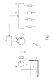
- 1 denotes an overall common-rail type system for the direct injection of fuel into an internal combustion engine provided with four cylinders (not shown in detail).
- the injection system 1 comprises four injectors 2, each of which is capable of injecting fuel directly into the crown of a respective cylinder (not shown in detail) of the engine and receives the pressurised fuel from a common rail 3.
- a high-pressure pump 4 supplies the fuel to the common rail 3 by means of a tube 5 and is equipped with a device 6 for regulating flow rate driven by a control unit 7 capable of maintaining the fuel pressure within the rail 3 at a desired value, which is generally variable over time as a function of the operating conditions of the engine.
- a low-pressure pump 8 with a substantially constant flow rate supplies the fuel from a tank 9 to the high-pressure pump 4 by means of a tube 10.
- control unit 7 regulates the flow rate of the high-pressure pump 4 by means of feedback control using as the feedback variable the fuel pressure level within the common rail 3, said pressure level being detected in real time by a sensor 11.
- the high-pressure pump 4 comprises a pair of cylinders 12 (only one of which is shown in Figure 2), each of which is provided with a piston 13 with reciprocating motion within the cylinder 12 under the thrust of a mechanical transmission (known and not shown); in particular, said mechanical transmission takes its motion from a drive shaft (not shown) of the engine and is capable of causing each piston 13 to perform one cycle (i.e. an intake stroke and a pumping stroke) for every two revolutions of the drive shaft.
- a mechanical transmission takes its motion from a drive shaft (not shown) of the engine and is capable of causing each piston 13 to perform one cycle (i.e. an intake stroke and a pumping stroke) for every two revolutions of the drive shaft.
- each cylinder 12 of the high-pressure pump 4 performs a compression phase or pump stroke and the high-pressure pump 4 performs two pump strokes; actuation of one piston 13 is shifted 360° out of phase relative to the actuation of the other piston 13, such that the pump strokes of the two pistons 13 are not superimposed on one another, but are symmetrically distributed so as to produce a compression phase or pump stroke of the high-pressure pump 4 on each revolution of the drive shaft.
- each cylinder 12 there is an intake channel 14 connected to the low-pressure pump 8 by means of the tube 10 and a delivery channel 15 connected to the common rail 3 by means of the tube 5.
- the intake channel 14 is controlled by a bidirectional intake valve 16, i.e. one that is capable of permitting fuel to pass both into and out of the cylinder 12, while the delivery channel 15 is regulated by a non-return delivery valve 17 that only permits fuel to flow out of the cylinder 12.
- the intake valve 16 comprises a valve body 18 that is mobile along the intake channel 14 and a valve seat 19, which is capable of being acted upon in a fluid-tight manner by the valve body 18 and is located at the opposite end of the intake channel 14 from the end communicating with the cylinder 12; a spring 20 is capable of pushing the valve body 18 towards a position of fluid-tight engagement with the valve seat 19.
- the intake valve 16 is normally pressure-actuated, in that the forces arising from the pressure differences across the intake valve 16 are greater than the force generated by the spring 20; in particular, in the absence of external intervention, the intake valve 16 is closed when the pressure of the fuel within the cylinder 12 is greater than the pressure of the fuel within the tube 10 and is open when the pressure of the fuel within the cylinder 12 is lower than the pressure of the fuel within the tube 10.
- the delivery valve 17 comprises a valve body 21 that is mobile along the delivery channel 15 and a valve seat 22, which is capable of being acted upon in a fluid-tight manner by the valve body 21 and is located at the opposite end of the delivery channel 15 from the end communicating with the cylinder 12; a spring 23 is capable of pushing the valve body 21 towards a position of fluid-tight engagement with the valve seat 22.
- the delivery valve 17 is pressure-actuated, in that the forces arising from the pressure differences across the delivery valve 17 are much greater than the force generated by the spring 23; in particular, in the absence of external intervention, the delivery valve 17 is open when the pressure of the fuel within the cylinder 12 is greater than the pressure of the fuel within the tube 5 (i.e. within the common rail 3) and is closed when the pressure of the fuel within the cylinder 12 is lower than the pressure of the fuel within the tube 5 (i.e. within the common rail 3).
- the regulating device 6 is coupled to the intake valve 16 in order to permit the control unit 7 to keep the intake valve 16 open during a compression phase of the piston 13 and so permit fuel to flow out from the cylinder 12 through the intake channel 14.
- the regulating device 6 comprises an actuating rod 24, which is coupled to the valve body 18 of the intake valve 16 and is mobile along a linear path that is parallel to the direction of flow of the fuel through the intake channel 14; in particular, the actuating rod 24 is mobile between a passive position, in which it permits the valve body 18 to act in a fluid-tight manner upon the respective valve seat 19, and an active position, in which it does not permit the valve body 18 to act in a fluid-tight manner upon the respective valve seat 19.
- the regulating device 6 also comprises an electromagnetic actuator 25, which is coupled to the actuating rod 24 in order to displace said actuating rod 24 between the active position and the passive position.
- the electromagnetic actuator 25 in turn comprises a spring 26 capable of keeping the actuating rod 24 in the active position and an electromagnet 27 controlled by the control unit 7 and capable of displacing the actuating rod 24 into the passive position by magnetically attracting a ferromagnetic armature 28 integral with the actuating rod 24; in particular, when the electromagnet 27 is energised, the actuating rod 24 is drawn back into the stated passive position and the intake channel 14 can be closed by the intake valve 16.
- the spring 26 of the electromagnetic actuator 25 exerts a greater force than the spring 20 of the intake valve 16 and thus, under resting conditions (i.e. in the absence of significant hydraulic forces and with the electromagnet 27 de-energised), the rod 24 is placed in the active position and the intake valve 16 is open (i.e. it is a normally open valve). In contrast, under resting conditions (i.e. in the absence of significant hydraulic forces), the delivery valve 17 is closed (i.e. it is a normally closed valve).
- the rod 24 rests against the valve body 18 of the intake valve 16, which is pushed towards the rod 24 by the action of the spring 20.
- the rod 24 is integral with the valve body 18 and it is possible to dispense with the spring 20.
- the regulating device 6 can be driven by the control unit 7 in order to bring the actuating rod 24 into the active position only when the pressure of the fuel within the cylinder 12 is at a relatively low level (substantially of the order of magnitude of the pressure provided by the low-pressure pump 8), because the electromagnetic actuator 25 is not absolutely capable of overcoming the pressure of the fuel generated by the pumping phase of the piston 13.
- the regulating device 6 can keep the actuating rod 24 in the active position, i.e. can keep the intake valve 16 open, only at the beginning of a pumping phase of the piston 13, but is not capable of bringing the actuating rod 24 into the active position, i.e. of opening the intake valve 16, during a pumping phase of the piston 13.
- the control unit 7 can actuate the electromagnet 27 with a current pulse that is of limited duration and is constant (for example less than 2 msec with actuation of the piston 13 performed at 3000 rpm); in fact, once the electromagnet 27 has brought the actuating rod 24 into the passive position by attracting to itself the armature 28, the intake valve 16 closes and a comparatively very high pressure is generated almost instantaneously within the cylinder 12, said pressure exerting on the valve body 18 of the intake valve 16 a force that is considerably higher than that exerted by the spring 26 of the actuator 25.
- the spring 26 of the actuator 25 is not capable of reopening the intake valve 16 until the pressure within the cylinder 12 has fallen to a relatively low level, i.e. until the beginning of the subsequent intake phase of the piston 13.
- Actuating the electromagnet 27 with a current pulse that is of limited duration and is constant is distinctly advantageous, because it makes it possible to restrict the energy consumption of the electromagnet 27 to the essential minimum, it makes it possible to reduce the costs of the associated electric circuits, because they can be dimensioned so as to operate with very low dissipated levels of electrical energy and it makes it possible to simplify the control circuit for the electromagnet 27.
- an overpressure valve 29 which serves to discharge the fuel from the tube 10 to the tank 9 when the pressure within the tube 10 exceeds a preset threshold value owing to the reflux of fuel from the cylinder 12.
- the function of the overpressure valve 29 is to prevent the pressure within the tube 10 from reaching relatively high values that could over time bring about the failure of the low-pressure pump 8.
- each piston 13 is provided with an inlet opening 31 to a channel 32 that extends within the piston 13 and ends at an outlet opening 33 provided on the side surface 34 of said piston 13.
- the side surface 35 of the cylinder 12 is provided with a discharge port 36, which is connected to the fuel tank 9 by means of a discharge duct 37 and is positioned such that it is aligned with and opposite the outlet opening 33 of the channel 32 during the upstroke or downstroke of the piston 13.
- the position of the discharge port 36 is selected so that it is always covered by the side surface of the piston 13 even when said piston 13 is located at its bottom dead centre.
- the position of the outlet opening 33 of the channel 32 is selected such that the outlet opening 33 is opposite the discharge port 36 when the piston 13 is located halfway through the upstroke (and, obviously, halfway through the downstroke).
- the discharge duct 37 communicating with the discharge port 36 is regulated by a non-return discharge valve capable of only permitting fuel to flow out of the cylinder 12 towards the fuel tank 9.
- the upper part of the cylinder 12 is full of fuel and the piston 13 reverses the direction of its stroke, beginning its upstroke or compression stroke.
- the piston 13 reverses the direction of its stroke, beginning its upstroke or compression stroke.
- a proportion of the fuel present in the upper part of the cylinder 12 must be discharged so as to supply the common rail 3 with only the quantity of fuel necessary to achieve the desired pressure value within the common rail 3.
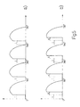
- Figures 3 show the pattern of the overall flow rate of the high-pressure pump 4 towards the common rail 3 as a function of engine angle, i.e. as a function of the angular position of the drive shaft, under two different operating conditions.
- Figure 3a shows the case in which the control unit 7 does not act at all on the intake valve 16, which thus closes as soon as the piston 13 compresses the fuel present within the cylinder 12 to a pressure level greater than the pressure level present in the tube 10; subsequently, the pressure within the cylinder 12 rises further until it reaches levels such as to bring about the opening of the delivery valve 17 and so permit the fuel to be supplied under pressure from the cylinder 12 to the common rail 3.
- Figure 3a shows the case in which the high-pressure pump 4 is required to supply the maximum possible quantity of fuel to the common rail 3, i.e. the case in which the control unit 7 does not act at all on the intake valve 16, which accordingly closes as soon as the piston 13 begins the upstroke.
- Figure 3b shows the case in which the high-pressure pump 4 is required to supply a quantity of fuel to the common rail 3 that is less than the maximum possible quantity, i.e. the case in which the control unit 7 acts on the intake valve 16, which accordingly remains open for a certain angular choking interval A (corresponding to a certain time interval) during the upstroke of each piston 13 in order to permit a certain proportion of the fuel present in the cylinder 12 to be reintroduced into the tube 10.
- the duration of the angular choking interval A depends on the quantity of fuel to be supplied to the common rail 3 and can vary between a minimum of zero (as shown in Figure 3a, corresponding to the case of maximum flow rate of the high-pressure pump 4 towards the common rail 3) and a maximum of approx. 180° (corresponding to the case of the intake valve 16 always being open and a zero flow rate of the high-pressure pump 4 towards the common rail 3).
- control unit 7 does not permit closure of the intake valve 16, which accordingly remains open for the angular choking interval A; in this manner, the pressure within the cylinder 12 does not reach levels such as to allow the delivery valve 17 to open and a proportion of the fuel leaves the cylinder 12 towards the tube 10, flowing through the intake channel 14.
- the control unit 7 drives the regulating device 6 so as to bring the actuating rod 24 into the passive position and so permit closure of the intake valve 16 as a result of the consequent increase in the pressure of the fuel within the cylinder 12; at this point, the pressure within the cylinder 12 rises owing to the upstroke of the piston 13 until it reaches levels such as to bring about the opening of the delivery valve 17 and thus allow fuel to be supplied under pressure from the cylinder 12 to the common rail 3.
- the control unit 7 drives the regulating device 6 so as to bring the actuating rod 24 into the passive position and so permit closure of the intake valve 16 as a result of the consequent increase in the pressure of the fuel within the cylinder 12; at this point, the pressure within the cylinder 12 rises owing to the upstroke of the piston 13 until it reaches levels such as to bring about opening of the delivery valve 17 again and thus allow fuel to be supplied under pressure from the cylinder 12 to the common rail 3.
- the piston 13 passes top dead centre and begins the downstroke or intake stroke, the pressure of the fuel within the cylinder 12 drops back down to low levels bringing about the closure of the delivery valve 17.
- delayed closure of the intake valve 16 in order to discharge fuel from the cylinder 12 to the tube 10 is repeated twice during the angular choking interval A: a first time at the beginning of the upstroke of the piston 13 and a second time halfway through the upstroke of the piston 13 immediately after the gap H caused by the channel 32.
- the regulating device 6 can be driven by the control unit 7 in order to bring the actuating rod 24 into the active position only when the pressure of the fuel within the cylinder 12 is at low levels (substantially of the order of magnitude of the pressure brought about by the low-pressure pump 8); the second opening of the intake valve 16 halfway through the upstroke of the piston 13 can only be achieved thanks to the presence of the channel 32, which brings about a substantial reduction in the pressure of the fuel within the cylinder 12 halfway through the upstroke of the piston 13.
- control unit 7 In order to vary the quantity of fuel supplied by the high-pressure pump 4 to the common rail 3, i.e. in order to vary the average flow rate of the high-pressure pump 4, the control unit 7 varies the quantity of fuel discharged through the intake channel 14, i.e. it varies the moment at which it drives the regulating device 6 in order to displace the actuating rod 24 from the active position to the passive position, consequently varying the duration of the angular choking interval A; as stated above, the control unit 7 varies the moment at which the regulating device 6 is driven by means of a feedback control using as the feedback variable the fuel pressure level within the common rail 3, said pressure level being detected in real time by the sensor 11.
- the duration of the angular choking interval A depends on the quantity of fuel to be supplied to the common rail 3 and can vary between a minimum of zero (as shown in Figure 3a, which corresponds to the case of maximum flow rate of the high-pressure pump 4 towards the common rail 3) and a maximum of approx. 180° (corresponding to the case of the intake valve 16 always being open and a zero flow rate of the high-pressure pump 4 towards the common rail 3).
- Each injector 2 performs its injection phase within an angular injection interval I, which typically has an amplitude of no greater than 40° of drive shaft revolution; in other words, depending on engine status, the injection phase of each injector 2 can be lengthened or shortened and can be advanced or delayed, but in each case the beginning and end of the injection (or the beginning of the first injection and the end of the final injection in the case of multiple injections) are always within an angular injection interval I that has an amplitude of no greater than 40° of drive shaft revolution.
- mechanical actuation of the high-pressure pump 4 is timed relative to the drive shaft so that two injection intervals I start at the beginning of the pumping phases (i.e. at 0° and 360° of drive shaft revolution) and so that two injection intervals I start halfway through the pumping phases just after the gap H (i.e. at approx. 180° and approx. 440° of drive shaft revolution).
- An alternative embodiment provides the timing of the mechanical actuation of the high-pressure pump 4 relative to the drive shaft so that two injection intervals I finish halfway through the pumping phases immediately before the gap H (i.e. at approx. 180° and approx. 440° of drive shaft revolution) and so that two injection intervals I finish at the end of the pumping phases (i.e. at 360° and 720° of drive shaft revolution); this embodiment places the emphasis on causing the injectors 2 to inject while the piston 13 of the high-pressure pump 4 is pumping fuel into the common rail 3.
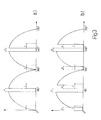
- the cylinder capacity of the high-pressure pump 4 is oversized relative to the embodiment described above and shown in Figure 3 and it is decided always to delay closure of the intake valve 16 by at least an angular interval equal to the angular injection interval I under each operating condition; in other words, irrespective of the quantity of fuel to be supplied to the common rail 3, the closure time of the intake valve 16 is always delayed by at least an angular interval equal to the angular injection interval I.
- Figure 4a shows the operation of the high-pressure pump 4 corresponding to supplying the common rail 3 with the maximum possible quantity of fuel; in this situation, the closure time of the intake valve 16 is delayed by an angular interval equal to the angular injection interval I.
- Figure 4b shows the operation of the high-pressure pump 4 corresponding to supplying the common rail 3 with a quantity of fuel that is less than the maximum possible quantity of fuel; in this situation, the closure time of the intake valve 16 is delayed by an angular interval greater than the angular injection interval I and in particular by an overall angular interval equal to the sum of the angular injection interval I and an angular choking interval A.
- all the injectors 2 always perform injection while the piston 13 of the high-pressure pump 4 is not pumping fuel into the common rail 3, irrespective of whether the pump stroke of the high-pressure pump 4 is or is not choked.
- the advantages of this embodiment are immediately obvious, in that because the injectors 2 always perform injection while the piston 13 of the high-pressure pump 4 is not pumping fuel, it is possible to make control of said injectors 2 simpler and more efficient.
- FIG. 1-4 relate to an engine having four cylinders and thus four injectors 2.
- an engine has a larger number of cylinders, for example six or eight cylinders, and thus a larger number of injectors 2
- the high-pressure pump 4 comprises four cylinders 12, each of which is provided with a piston 13 that has an alternating motion within the cylinder 12 under the thrust of the mechanical transmission (known and not shown); in particular, said mechanical transmission takes its motion from the drive shaft (not shown) of the engine and is capable of causing each piston 13 to perform one cycle (i.e. an intake stroke and a pumping stroke) for every two revolutions of the drive shaft.
- said mechanical transmission takes its motion from the drive shaft (not shown) of the engine and is capable of causing each piston 13 to perform one cycle (i.e. an intake stroke and a pumping stroke) for every two revolutions of the drive shaft.
- each cylinder 12 performs a pump stroke and the high-pressure pump 4 makes four pump strokes; actuation of each piston 13 is shifted out of phase by a multiple of 180° relative to the actuation of the other pistons 13, such that the four pump strokes are not superimposed on one another, but are symmetrically distributed so as to obtain a pump stroke of the high-pressure pump 4 on each half revolution of the drive shaft.
- Figure 5a shows the operation of the high-pressure pump 4 corresponding to supplying the common rail 3 with the maximum possible quantity of fuel; in this situation, the closure time of the intake valve 16 is delayed by an angular interval equal to the angular injection interval I.
- Figure 5b shows the operation of the high-pressure pump 4 corresponding to supplying the common rail 3 with a quantity of fuel that is less than the maximum possible quantity of fuel; in this situation, the closure time of the intake valve 16 is delayed by an angular interval greater than the angular injection interval I and in particular by an overall angular interval equal to the sum of the angular injection interval I and an angular choking interval A.
Abstract
Description
- The present invention relates to a method and a system for the direct injection of fuel into an internal combustion engine, in particular for direct fuel injection of the common rail type.
- In current common-rail type direct injection systems, a low-pressure pump supplies fuel from a tank to a high-pressure pump, which in turn supplies the fuel to a common rail. A series of injectors (one for each cylinder of the engine) is connected to the common rail, said injectors being driven cyclically in order to inject part of the pressurised fuel present in the common rail into a respective cylinder. If the injection system is to operate correctly, it is important for the fuel pressure level within the common rail constantly to be maintained at a desired value that generally varies over time; to this end, the high-pressure pump is dimensioned so as to supply the common rail in any operating state with a quantity of fuel that exceeds actual consumption and a pressure regulator is coupled to the common rail, which regulator maintains the fuel pressure level within the common rail at the desired value by discharging excess fuel to a recirculation channel that reintroduces said excess fuel upstream from the low-pressure pump.
- Known injection systems of the type described above have various disadvantages, because the high-pressure pump must be dimensioned so as to supply the common rail with a quantity of fuel that slightly exceeds the maximum possible consumption; however, this maximum possible consumption state occurs relatively rarely and in all other operating states the quantity of fuel supplied to the common rail by the high-pressure pump is much greater than that actually consumed and thus a considerable proportion of said fuel must be discharged by the pressure regulator into the recirculation channel. Obviously, the work performed by the high-pressure pump in pumping fuel that is subsequently discharged by the pressure regulator is "pointless" work and such known injection systems accordingly have very low energy efficiency. Moreover, such known injection systems have a tendency to overheat the fuel, because when the excess fuel is discharged by the pressure regulator into recirculation channel, said fuel passes from a very high pressure (greater than 1000 bar) to a substantially ambient pressure and this pressure drop tends to increase the temperature of the fuel. Finally, known injection systems of the type described above are relatively bulky owing to the presence of the pressure regulator and the recirculation channel connected to the pressure regulator.
- In order to overcome the problems described above, a solution has been proposed of the type presented in patent application EP0481964A1, which describes the use of a high-pressure pump with a variable flow rate, which is capable of supplying the common rail with only the quantity of fuel that is necessary to maintain the fuel pressure within the common rail at the desired value; in particular, the high-pressure pump is equipped with an electromagnetic actuator capable of instantaneously varying the flow rate of the high-pressure pump by varying the closure time of an intake valve of the high-pressure pump itself.
- Another embodiment of a high-pressure pump with a variable flow rate is described by patent US6116870A1. In particular, the high-pressure pump described by US6116870A1 comprises a cylinder provided with a piston that has reciprocating motion within the cylinder, an intake channel, a delivery channel coupled to the common rail, an intake valve capable of permitting fuel to flow into the cylinder, a non-return delivery valve coupled to the delivery channel and capable only of permitting fuel to flow out of the cylinder, and a regulating device coupled to the intake valve in order to keep the intake valve open during a compression phase of the piston and so permit the fuel to flow out of the cylinder through the intake channel. The intake valve comprises a valve body that is mobile along the intake channel and a valve seat, which is capable of being acted upon in a fluid-tight manner by the valve body and is located at the opposite end of the intake channel from the end communicating with the cylinder. The regulating device comprises an actuating body, which is coupled to the valve body and can move between a passive position, in which it permits the valve body to act in a fluid-tight manner upon the valve seat, and an active position, in which it does not permit the valve body to act in a fluid-tight manner upon the valve seat; the actuating body is coupled to an electromagnetic actuator, which is capable of displacing the actuating body between the passive position and the active position.
- As stated above, in the above-described high-pressure pumps with a variable flow rate, the flow rate of a high-pressure pump is varied by varying the closure time of the intake valve of said high-pressure pump; in particular, the flow rate is reduced by delaying the closure time of the intake valve and is increased by advancing the closure time of the intake valve.
- In general, the above-described high-pressure pumps with a variable flow rate have two cylinders, along each of which there runs a piston that completes one cycle (i.e. performs an intake stroke and a pumping stroke) for every two revolutions of the drive shaft; thus, for every two complete revolutions of the drive shaft, the high-pressure pump makes two pump strokes (one for each cylinder of the high-pressure pump). In a four-cylinder, four-stroke internal combustion engine, for each complete revolution of the drive shaft, one pump stroke of the high-pressure pump and the injection phase of two injectors take place. When the flow rate required is equal or close to the maximum flow rate of the pump, both the injectors performing the injection phase during any one revolution of the drive shaft inject the fuel while a piston of the high-pressure pump is pumping the fuel into the common rail; when the required flow rate is less than the maximum flow rate of the high-pressure pump, the pump stroke is choked and thus a first one of the injectors performing the injection phase during any one revolution of the drive shaft injects the fuel while neither piston of the high-pressure pump is pumping fuel into the common rail, whereas a second one of the injectors performing the injection phase during any one revolution of the drive shaft injects the fuel while one piston of the high-pressure pump is pumping fuel into the common rail. The disparity described above, which arises between the two injectors performing the injection phase during the same revolution of the drive shaft results in a disparity in the quantity of fuel injected by the two injectors with an identical injection time, with obvious repercussions on the correct operation of the engine; moreover, this disparity does not always occur to the same extent, but there is a substantial difference when the flow rate required from the high-pressure pump is lower than a certain threshold value corresponding to the value at which choking of the high-pressure pump coincides with the beginning of the injection phase of the first injector to inject, out of the two injectors performing the injection phase during the same revolution of the drive shaft.
- In order to overcome the above-described disadvantage, at least in part, it has been proposed to use a high-pressure pump with a variable flow rate having two cylinders, along each of which there runs a piston that completes one cycle (i.e. performs an intake stroke and a pumping stroke) for each revolution of the drive shaft. Thus, in a four-cylinder, four-stroke internal combustion engine, for each complete revolution of the drive shaft, two pump strokes of the high-pressure pump and the injection phase of two injectors take place; in this manner, just one injection phase of one of the injectors always takes place during each pump stroke of the high-pressure pump. When the required flow rate is equal or close to the maximum flow rate of the pump, all the injectors inject the fuel while one piston of the high-pressure pump is pumping fuel into the common rail; when the required flow rate is less than the maximum flow rate of the high-pressure pump, the pump stroke is choked and all the injectors inject the fuel while neither piston of the high-pressure pump is pumping fuel into the common rail. Obviously, the disparity in the behaviour of the injectors is reduced because, within any one control interval, either all the injectors perform injection while one piston of the high-pressure pump is pumping fuel into the common rail, or all the injectors perform injection while neither piston of the high-pressure pump is pumping fuel into the common rail; nevertheless, a slight disparity in behaviour remains in that in some control intervals the injectors have certain dynamic characteristics because they are injecting while one piston of the high-pressure pump is pumping fuel into the common rail, whereas in other control intervals the injectors have different dynamic characteristics because they are injecting while neither piston of the high-pressure pump is pumping fuel into the common rail.
- Moreover, making the pistons of the high-pressure pump perform one cycle (i.e. an intake stroke and a pumping stroke) on each revolution of the drive shaft instead of one cycle every two revolutions of the drive shaft entails doubling the average velocity of said pistons with obvious problems of mechanical strength and reliability over time. Alternatively, it has been proposed to use high-pressure pumps equipped with four cylinders and thus with four pistons, each of which performs one cycle every two revolutions of the drive shaft; however, while this solution is more straightforward to implement, it involves substantially higher costs and bulkiness of the high-pressure pump.
- EP0962650A1 discloses an accumulator-type fuel injection apparatus having a plurality of fuel injection valves for corresponding individual cylinders of an engine; the fuel injection valves are connected to a common pressure-accumulator chamber that is connected to an ejection side of a fuel pump. Fuel is pumped from the fuel pump into the pressure-accumulator chamber and then supplied into the cylinders via the corresponding fuel injection valves; the fuel pumping timing of the fuel pump is set relative to the fuel injection timing so that a variation in fuel pressure in the pressure-accumulating chamber at the time of start of a fuel injecting operation is smaller than a predetermined set value.
- EP1130250A1 discloses a pump having a housing with working chamber, reciprocally moving piston rotatably mounted about its longitudinal axis and at least one inlet opening; opening in piston casing is connected to working chamber, interacts with inlet opening and is designed so liquid flowing into working chamber can be adjusted to turn the piston, which has radial groove with radial depth of at least one per cent of piston diameter. The pump has a pump housing with a working chamber, a reciprocally moving piston rotatably mounted about its longitudinal axis and at least one inlet opening; an opening in the piston casing is connected to the working chamber, interacts with the inlet opening and is designed so the liquid flowing into the working chamber can be adjusted to turn the piston. A groove extending along the periphery of the piston has a radial depth amounting to at least one per cent of the piston diameter.
- EP0501459A1 discloses a common-rail fuel injection system for an engine including a common rail for storing fuel; a plurality of pumps supply fuel to the common rail. Fuel is injected into the engine from the common rail and feedback control is executed on the pressure of the fuel in the common rail; a device serves to detect whether or not at least one of the pumps fails and an arrangement decreases the pressure of the fuel in the common rail when the detecting device detects that at least one of the pumps fails.
- EP1241338A1 discloses a fuel supply system, which reduces the unevenness of injection rates of cylinders in a fuel supply system of a direct injection engine which uses a variable displacement single plunger pump; the unevenness of injection rates of cylinders can be reduced by constructing so that the cam which drives the high-pressure fuel pump may make one reciprocation while the engine makes explosions by two cylinders and causing the controller to extend the injection time width of one of two injectors which inject while one discharge of the high-pressure fuel pump and to shorten the injection time width of the other injector.
- The aim of the present invention is to provide a method and a system for the direct injection of fuel into an internal combustion engine, which method and system do not have the above-described disadvantages and, in particular, are simple and economic to implement.
- The present invention provides a method and a system for the direct injection of fuel into an internal combustion engine as recited in the attached claims.
- The present invention will now be described with reference to the attached drawings, which illustrate some non-limiting embodiments thereof, in which:
- Figure 1 is a diagrammatic view of a common-rail type direct fuel injection system produced according to the present invention;
- Figure 2 is a cross-sectional diagrammatic view of a high-pressure pump of the system in Figure 1;
- Figure 3 shows graphs of the variation in flow rate of the high-pressure pump in Figure 2 in different operating states;
- Figure 4 shows graphs of the variation in flow rate of the high-pressure pump in Figure 2 in different operating states and in accordance with a different embodiment of the control strategies; and
- Figure 5 shows graphs of the variation in flow rate in different operating states of a high-pressure pump produced according to a different embodiment.
- In Figure 1, 1 denotes an overall common-rail type system for the direct injection of fuel into an internal combustion engine provided with four cylinders (not shown in detail). The injection system 1 comprises four
injectors 2, each of which is capable of injecting fuel directly into the crown of a respective cylinder (not shown in detail) of the engine and receives the pressurised fuel from acommon rail 3. A high-pressure pump 4 supplies the fuel to thecommon rail 3 by means of atube 5 and is equipped with adevice 6 for regulating flow rate driven by acontrol unit 7 capable of maintaining the fuel pressure within therail 3 at a desired value, which is generally variable over time as a function of the operating conditions of the engine. A low-pressure pump 8 with a substantially constant flow rate supplies the fuel from atank 9 to the high-pressure pump 4 by means of atube 10. - In general, the
control unit 7 regulates the flow rate of the high-pressure pump 4 by means of feedback control using as the feedback variable the fuel pressure level within thecommon rail 3, said pressure level being detected in real time by asensor 11. - As shown in Figure 2, the high-
pressure pump 4 comprises a pair of cylinders 12 (only one of which is shown in Figure 2), each of which is provided with apiston 13 with reciprocating motion within thecylinder 12 under the thrust of a mechanical transmission (known and not shown); in particular, said mechanical transmission takes its motion from a drive shaft (not shown) of the engine and is capable of causing eachpiston 13 to perform one cycle (i.e. an intake stroke and a pumping stroke) for every two revolutions of the drive shaft. Thus, for every two revolutions of the drive shaft, eachcylinder 12 of the high-pressure pump 4 performs a compression phase or pump stroke and the high-pressure pump 4 performs two pump strokes; actuation of onepiston 13 is shifted 360° out of phase relative to the actuation of theother piston 13, such that the pump strokes of the twopistons 13 are not superimposed on one another, but are symmetrically distributed so as to produce a compression phase or pump stroke of the high-pressure pump 4 on each revolution of the drive shaft. - On the crown of each
cylinder 12, there is anintake channel 14 connected to the low-pressure pump 8 by means of thetube 10 and adelivery channel 15 connected to thecommon rail 3 by means of thetube 5. Theintake channel 14 is controlled by abidirectional intake valve 16, i.e. one that is capable of permitting fuel to pass both into and out of thecylinder 12, while thedelivery channel 15 is regulated by anon-return delivery valve 17 that only permits fuel to flow out of thecylinder 12. - The
intake valve 16 comprises avalve body 18 that is mobile along theintake channel 14 and avalve seat 19, which is capable of being acted upon in a fluid-tight manner by thevalve body 18 and is located at the opposite end of theintake channel 14 from the end communicating with thecylinder 12; aspring 20 is capable of pushing thevalve body 18 towards a position of fluid-tight engagement with thevalve seat 19. Theintake valve 16 is normally pressure-actuated, in that the forces arising from the pressure differences across theintake valve 16 are greater than the force generated by thespring 20; in particular, in the absence of external intervention, theintake valve 16 is closed when the pressure of the fuel within thecylinder 12 is greater than the pressure of the fuel within thetube 10 and is open when the pressure of the fuel within thecylinder 12 is lower than the pressure of the fuel within thetube 10. - The
delivery valve 17 comprises avalve body 21 that is mobile along thedelivery channel 15 and avalve seat 22, which is capable of being acted upon in a fluid-tight manner by thevalve body 21 and is located at the opposite end of thedelivery channel 15 from the end communicating with thecylinder 12; aspring 23 is capable of pushing thevalve body 21 towards a position of fluid-tight engagement with thevalve seat 22. Thedelivery valve 17 is pressure-actuated, in that the forces arising from the pressure differences across thedelivery valve 17 are much greater than the force generated by thespring 23; in particular, in the absence of external intervention, thedelivery valve 17 is open when the pressure of the fuel within thecylinder 12 is greater than the pressure of the fuel within the tube 5 (i.e. within the common rail 3) and is closed when the pressure of the fuel within thecylinder 12 is lower than the pressure of the fuel within the tube 5 (i.e. within the common rail 3). - The regulating
device 6 is coupled to theintake valve 16 in order to permit thecontrol unit 7 to keep theintake valve 16 open during a compression phase of thepiston 13 and so permit fuel to flow out from thecylinder 12 through theintake channel 14. Theregulating device 6 comprises anactuating rod 24, which is coupled to thevalve body 18 of theintake valve 16 and is mobile along a linear path that is parallel to the direction of flow of the fuel through theintake channel 14; in particular, the actuatingrod 24 is mobile between a passive position, in which it permits thevalve body 18 to act in a fluid-tight manner upon therespective valve seat 19, and an active position, in which it does not permit thevalve body 18 to act in a fluid-tight manner upon therespective valve seat 19. Theregulating device 6 also comprises anelectromagnetic actuator 25, which is coupled to the actuatingrod 24 in order to displace said actuatingrod 24 between the active position and the passive position. Theelectromagnetic actuator 25 in turn comprises aspring 26 capable of keeping theactuating rod 24 in the active position and anelectromagnet 27 controlled by thecontrol unit 7 and capable of displacing the actuatingrod 24 into the passive position by magnetically attracting aferromagnetic armature 28 integral with the actuatingrod 24; in particular, when theelectromagnet 27 is energised, the actuatingrod 24 is drawn back into the stated passive position and theintake channel 14 can be closed by theintake valve 16. - The
spring 26 of theelectromagnetic actuator 25 exerts a greater force than thespring 20 of theintake valve 16 and thus, under resting conditions (i.e. in the absence of significant hydraulic forces and with theelectromagnet 27 de-energised), therod 24 is placed in the active position and theintake valve 16 is open (i.e. it is a normally open valve). In contrast, under resting conditions (i.e. in the absence of significant hydraulic forces), thedelivery valve 17 is closed (i.e. it is a normally closed valve). - According to the embodiment shown in Figure 2, the
rod 24 rests against thevalve body 18 of theintake valve 16, which is pushed towards therod 24 by the action of thespring 20. According to a different embodiment, not shown, therod 24 is integral with thevalve body 18 and it is possible to dispense with thespring 20. - The regulating
device 6 can be driven by thecontrol unit 7 in order to bring the actuatingrod 24 into the active position only when the pressure of the fuel within thecylinder 12 is at a relatively low level (substantially of the order of magnitude of the pressure provided by the low-pressure pump 8), because theelectromagnetic actuator 25 is not absolutely capable of overcoming the pressure of the fuel generated by the pumping phase of thepiston 13. In other words, theregulating device 6 can keep the actuatingrod 24 in the active position, i.e. can keep theintake valve 16 open, only at the beginning of a pumping phase of thepiston 13, but is not capable of bringing the actuatingrod 24 into the active position, i.e. of opening theintake valve 16, during a pumping phase of thepiston 13. - The
control unit 7 can actuate theelectromagnet 27 with a current pulse that is of limited duration and is constant (for example less than 2 msec with actuation of thepiston 13 performed at 3000 rpm); in fact, once theelectromagnet 27 has brought the actuatingrod 24 into the passive position by attracting to itself thearmature 28, theintake valve 16 closes and a comparatively very high pressure is generated almost instantaneously within thecylinder 12, said pressure exerting on thevalve body 18 of the intake valve 16 a force that is considerably higher than that exerted by thespring 26 of theactuator 25. Thus, if ever theelectromagnet 27 ceases to act, thespring 26 of theactuator 25 is not capable of reopening theintake valve 16 until the pressure within thecylinder 12 has fallen to a relatively low level, i.e. until the beginning of the subsequent intake phase of thepiston 13. Actuating theelectromagnet 27 with a current pulse that is of limited duration and is constant is distinctly advantageous, because it makes it possible to restrict the energy consumption of theelectromagnet 27 to the essential minimum, it makes it possible to reduce the costs of the associated electric circuits, because they can be dimensioned so as to operate with very low dissipated levels of electrical energy and it makes it possible to simplify the control circuit for theelectromagnet 27. - According to a preferred embodiment, along the
tube 10 downstream from the low-pressure pump 8 there is inserted an overpressure valve 29, which serves to discharge the fuel from thetube 10 to thetank 9 when the pressure within thetube 10 exceeds a preset threshold value owing to the reflux of fuel from thecylinder 12. The function of the overpressure valve 29 is to prevent the pressure within thetube 10 from reaching relatively high values that could over time bring about the failure of the low-pressure pump 8. - The
upper surface 30 of eachpiston 13 is provided with aninlet opening 31 to achannel 32 that extends within thepiston 13 and ends at anoutlet opening 33 provided on theside surface 34 of saidpiston 13. Theside surface 35 of thecylinder 12 is provided with adischarge port 36, which is connected to thefuel tank 9 by means of adischarge duct 37 and is positioned such that it is aligned with and opposite the outlet opening 33 of thechannel 32 during the upstroke or downstroke of thepiston 13. The position of thedischarge port 36 is selected so that it is always covered by the side surface of thepiston 13 even when saidpiston 13 is located at its bottom dead centre. The position of the outlet opening 33 of thechannel 32 is selected such that theoutlet opening 33 is opposite thedischarge port 36 when thepiston 13 is located halfway through the upstroke (and, obviously, halfway through the downstroke). According to another embodiment, not shown, thedischarge duct 37 communicating with thedischarge port 36 is regulated by a non-return discharge valve capable of only permitting fuel to flow out of thecylinder 12 towards thefuel tank 9. - In use, during the downstroke or intake stroke of each
piston 13 within thecylinder 12, a vacuum is generated and a constant quantity of fuel equal in volume to the capacity of thecylinder 12 is introduced into thecylinder 12 through theintake channel 14. Halfway through the downstroke of thepiston 13, the outlet opening 33 of thechannel 32 is located opposite thedischarge port 36; however, under these conditions there is no appreciable passage of fuel through thedischarge port 36 because the pressure of the fuel present in the upper part of thecylinder 12 is low and substantially similar to the pressure present within thefuel tank 9. - Once the
piston 13 has reached its bottom dead centre, the upper part of thecylinder 12 is full of fuel and thepiston 13 reverses the direction of its stroke, beginning its upstroke or compression stroke. There is more fuel present in the upper part of thecylinder 12 than is necessary in order to obtain the desired pressure value within thecommon rail 3; therefore, a proportion of the fuel present in the upper part of thecylinder 12 must be discharged so as to supply thecommon rail 3 with only the quantity of fuel necessary to achieve the desired pressure value within thecommon rail 3. - Figures 3 show the pattern of the overall flow rate of the high-
pressure pump 4 towards thecommon rail 3 as a function of engine angle, i.e. as a function of the angular position of the drive shaft, under two different operating conditions. In particular, Figure 3a shows the case in which thecontrol unit 7 does not act at all on theintake valve 16, which thus closes as soon as thepiston 13 compresses the fuel present within thecylinder 12 to a pressure level greater than the pressure level present in thetube 10; subsequently, the pressure within thecylinder 12 rises further until it reaches levels such as to bring about the opening of thedelivery valve 17 and so permit the fuel to be supplied under pressure from thecylinder 12 to thecommon rail 3. This situation is maintained until halfway through the upstroke of the piston when the outlet opening 33 of thechannel 32 is located opposite thedischarge port 36; at this point a proportion of the fuel present in the upper part of thecylinder 12 flows through thedischarge duct 37 because the pressure of the fuel present in the upper part of thecylinder 12 is much higher than the pressure of the fuel in thedischarge duct 37. Consequently, the pressure of the fuel within thecylinder 12 drops rapidly until it reaches levels close to the pressure of the fuel in thetube 10 and thedelivery valve 17 accordingly closes. Said situation prevails while the outlet opening 33 of thechannel 32 is in communication with thedischarge port 36; as soon as the upstroke of thepiston 13 moves the outlet opening 33 of thechannel 32 away from thedischarge port 36, the flow of fuel through thedischarge duct 37 ceases and the pressure of the fuel within thecylinder 12 rises once more until thedelivery valve 17 is reopened. When thepiston 13 passes top dead centre and begins the downstroke or intake stroke, the pressure of the fuel within thecylinder 12 drops back down to low levels bringing about the closure of thedelivery valve 17. - The situation explained above is clearly visible in Figure 3a, in which the pattern of the flow rate of the high-
pressure pump 4 towards thecommon rail 3 is shown as a function of engine angle (i.e. of the angular position of the drive shaft); in particular, the pattern of the flow rate of the high-pressure pump 4 towards thecommon rail 3 is shown during two successive complete revolutions of the drive shaft, i.e. over the course of 720° of engine revolution. In Figure 3a, the effect of thechannel 32 is clearly visible, producing a gap H in the flow rate of the high-pressure pump 4 towards thecommon rail 3 at around 180° and around 440°, i.e. corresponding to halfway through the upstroke of thepistons 13. - Figure 3a shows the case in which the high-
pressure pump 4 is required to supply the maximum possible quantity of fuel to thecommon rail 3, i.e. the case in which thecontrol unit 7 does not act at all on theintake valve 16, which accordingly closes as soon as thepiston 13 begins the upstroke. Figure 3b, in contrast, shows the case in which the high-pressure pump 4 is required to supply a quantity of fuel to thecommon rail 3 that is less than the maximum possible quantity, i.e. the case in which thecontrol unit 7 acts on theintake valve 16, which accordingly remains open for a certain angular choking interval A (corresponding to a certain time interval) during the upstroke of eachpiston 13 in order to permit a certain proportion of the fuel present in thecylinder 12 to be reintroduced into thetube 10. The duration of the angular choking interval A depends on the quantity of fuel to be supplied to thecommon rail 3 and can vary between a minimum of zero (as shown in Figure 3a, corresponding to the case of maximum flow rate of the high-pressure pump 4 towards the common rail 3) and a maximum of approx. 180° (corresponding to the case of theintake valve 16 always being open and a zero flow rate of the high-pressure pump 4 towards the common rail 3). - In particular, during an initial phase of the upstroke, the
control unit 7 does not permit closure of theintake valve 16, which accordingly remains open for the angular choking interval A; in this manner, the pressure within thecylinder 12 does not reach levels such as to allow thedelivery valve 17 to open and a proportion of the fuel leaves thecylinder 12 towards thetube 10, flowing through theintake channel 14. Once the angular choking interval A has passed, thecontrol unit 7 drives theregulating device 6 so as to bring theactuating rod 24 into the passive position and so permit closure of theintake valve 16 as a result of the consequent increase in the pressure of the fuel within thecylinder 12; at this point, the pressure within thecylinder 12 rises owing to the upstroke of thepiston 13 until it reaches levels such as to bring about the opening of thedelivery valve 17 and thus allow fuel to be supplied under pressure from thecylinder 12 to thecommon rail 3. Owing to the above-described action of thechannel 32, halfway through the upstroke of thepiston 13, the pressure of the fuel within thecylinder 12 drops distinctly, bringing about the closure of thedelivery valve 17; before the pressure within thecylinder 12 begins to rise again, thecontrol unit 7 again drives theregulating device 6 so as to bring theactuating rod 24 into the active position, bringing about the opening of theintake valve 16 for the angular choking interval A. A proportion of the fuel present within thecylinder 12 thus again leaves saidcylinder 12 towards thetube 10 flowing through theintake channel 14. Once the angular choking interval A has passed, thecontrol unit 7 drives theregulating device 6 so as to bring theactuating rod 24 into the passive position and so permit closure of theintake valve 16 as a result of the consequent increase in the pressure of the fuel within thecylinder 12; at this point, the pressure within thecylinder 12 rises owing to the upstroke of thepiston 13 until it reaches levels such as to bring about opening of thedelivery valve 17 again and thus allow fuel to be supplied under pressure from thecylinder 12 to thecommon rail 3. When thepiston 13 passes top dead centre and begins the downstroke or intake stroke, the pressure of the fuel within thecylinder 12 drops back down to low levels bringing about the closure of thedelivery valve 17. - In other words, during any one pump stroke of each
piston 13, i.e. during any one upstroke or compression stroke of thepiston 13, delayed closure of theintake valve 16 in order to discharge fuel from thecylinder 12 to thetube 10 is repeated twice during the angular choking interval A: a first time at the beginning of the upstroke of thepiston 13 and a second time halfway through the upstroke of thepiston 13 immediately after the gap H caused by thechannel 32. - As stated above, the regulating
device 6 can be driven by thecontrol unit 7 in order to bring theactuating rod 24 into the active position only when the pressure of the fuel within thecylinder 12 is at low levels (substantially of the order of magnitude of the pressure brought about by the low-pressure pump 8); the second opening of theintake valve 16 halfway through the upstroke of thepiston 13 can only be achieved thanks to the presence of thechannel 32, which brings about a substantial reduction in the pressure of the fuel within thecylinder 12 halfway through the upstroke of thepiston 13. - In order to vary the quantity of fuel supplied by the high-
pressure pump 4 to thecommon rail 3, i.e. in order to vary the average flow rate of the high-pressure pump 4, thecontrol unit 7 varies the quantity of fuel discharged through theintake channel 14, i.e. it varies the moment at which it drives theregulating device 6 in order to displace theactuating rod 24 from the active position to the passive position, consequently varying the duration of the angular choking interval A; as stated above, thecontrol unit 7 varies the moment at which theregulating device 6 is driven by means of a feedback control using as the feedback variable the fuel pressure level within thecommon rail 3, said pressure level being detected in real time by thesensor 11. As stated above, the duration of the angular choking interval A depends on the quantity of fuel to be supplied to thecommon rail 3 and can vary between a minimum of zero (as shown in Figure 3a, which corresponds to the case of maximum flow rate of the high-pressure pump 4 towards the common rail 3) and a maximum of approx. 180° (corresponding to the case of theintake valve 16 always being open and a zero flow rate of the high-pressure pump 4 towards the common rail 3). - Each
injector 2 performs its injection phase within an angular injection interval I, which typically has an amplitude of no greater than 40° of drive shaft revolution; in other words, depending on engine status, the injection phase of eachinjector 2 can be lengthened or shortened and can be advanced or delayed, but in each case the beginning and end of the injection (or the beginning of the first injection and the end of the final injection in the case of multiple injections) are always within an angular injection interval I that has an amplitude of no greater than 40° of drive shaft revolution. - As shown in Figure 3, mechanical actuation of the high-
pressure pump 4 is timed relative to the drive shaft so that two injection intervals I start at the beginning of the pumping phases (i.e. at 0° and 360° of drive shaft revolution) and so that two injection intervals I start halfway through the pumping phases just after the gap H (i.e. at approx. 180° and approx. 440° of drive shaft revolution). In this manner, it is obvious that where the pump strokes are not choked (Figure 3a), all four of theinjectors 2 perform injection while thepiston 13 of the high-pressure pump 4 is pumping fuel into thecommon rail 3; on the other hand, where the pump strokes are choked (Figure 3b), all four of theinjectors 2 perform injection while thepiston 13 of the high-pressure pump 4 is not pumping fuel into thecommon rail 3 or while thepiston 13 of the high-pressure pump 4 is pumping fuel into thecommon rail 3, depending on the duration of the angular choking interval A. In each situation, all four of theinjectors 2 always inject under identical general conditions with obvious benefits in terms of simplicity and efficiency of control of saidinjectors 2. - An alternative embodiment provides the timing of the mechanical actuation of the high-
pressure pump 4 relative to the drive shaft so that two injection intervals I finish halfway through the pumping phases immediately before the gap H (i.e. at approx. 180° and approx. 440° of drive shaft revolution) and so that two injection intervals I finish at the end of the pumping phases (i.e. at 360° and 720° of drive shaft revolution); this embodiment places the emphasis on causing theinjectors 2 to inject while thepiston 13 of the high-pressure pump 4 is pumping fuel into thecommon rail 3. - According to another embodiment shown in Figure 4, the cylinder capacity of the high-pressure pump 4 is oversized relative to the embodiment described above and shown in Figure 3 and it is decided always to delay closure of the intake valve 16 by at least an angular interval equal to the angular injection interval I under each operating condition; in other words, irrespective of the quantity of fuel to be supplied to the common rail 3, the closure time of the intake valve 16 is always delayed by at least an angular interval equal to the angular injection interval I. Figure 4a shows the operation of the high-pressure pump 4 corresponding to supplying the common rail 3 with the maximum possible quantity of fuel; in this situation, the closure time of the intake valve 16 is delayed by an angular interval equal to the angular injection interval I. Figure 4b shows the operation of the high-pressure pump 4 corresponding to supplying the common rail 3 with a quantity of fuel that is less than the maximum possible quantity of fuel; in this situation, the closure time of the intake valve 16 is delayed by an angular interval greater than the angular injection interval I and in particular by an overall angular interval equal to the sum of the angular injection interval I and an angular choking interval A. By proceeding in accordance with the situation in Figure 4, all the injectors 2 always perform injection while the piston 13 of the high-pressure pump 4 is not pumping fuel into the common rail 3, irrespective of whether the pump stroke of the high-pressure pump 4 is or is not choked. The advantages of this embodiment are immediately obvious, in that because the
injectors 2 always perform injection while thepiston 13 of the high-pressure pump 4 is not pumping fuel, it is possible to make control of saidinjectors 2 simpler and more efficient. - The embodiments shown in Figures 1-4 relate to an engine having four cylinders and thus four
injectors 2. Where an engine has a larger number of cylinders, for example six or eight cylinders, and thus a larger number ofinjectors 2, it is possible to have two or threedischarge ports 36 mutually symmetrically arranged along theside surface 35 of thepiston 13 so as to create two or three gaps H in each pump stroke of the high-pressure pump 4; in this manner, it is possible to subdivide the choking of the pump stroke symmetrically into three or four phases, the first of which being at the beginning of the pump stroke and the others after each gap H. - According to a further embodiment shown in Figure 5, the high-
pressure pump 4 comprises fourcylinders 12, each of which is provided with apiston 13 that has an alternating motion within thecylinder 12 under the thrust of the mechanical transmission (known and not shown); in particular, said mechanical transmission takes its motion from the drive shaft (not shown) of the engine and is capable of causing eachpiston 13 to perform one cycle (i.e. an intake stroke and a pumping stroke) for every two revolutions of the drive shaft. Thus, for every two revolutions of the drive shaft, eachcylinder 12 performs a pump stroke and the high-pressure pump 4 makes four pump strokes; actuation of eachpiston 13 is shifted out of phase by a multiple of 180° relative to the actuation of theother pistons 13, such that the four pump strokes are not superimposed on one another, but are symmetrically distributed so as to obtain a pump stroke of the high-pressure pump 4 on each half revolution of the drive shaft. - As shown in Figure 5, since there are four pump strokes of the high-
pressure pump 4 for every two revolutions of the drive shaft, the presence of thechannel 32 is no longer necessary because the injection of asingle injector 2 corresponds to each pump stroke of the high-pressure pump 4. In a similar manner to that already stated for the embodiment in Figure 4, it is decided always to delay closure of the intake valve 16 by at least an angular interval equal to the angular injection interval I under each operating condition; in other words, irrespective of the quantity of fuel to be supplied to the common rail 3, the closure time of the intake valve 16 is always delayed by at least an angular interval equal to the angular injection interval I. Figure 5a shows the operation of the high-pressure pump 4 corresponding to supplying the common rail 3 with the maximum possible quantity of fuel; in this situation, the closure time of the intake valve 16 is delayed by an angular interval equal to the angular injection interval I. Figure 5b shows the operation of the high-pressure pump 4 corresponding to supplying the common rail 3 with a quantity of fuel that is less than the maximum possible quantity of fuel; in this situation, the closure time of the intake valve 16 is delayed by an angular interval greater than the angular injection interval I and in particular by an overall angular interval equal to the sum of the angular injection interval I and an angular choking interval A. By proceeding in accordance with the situation shown in Figure 5, all the injectors 2 always perform injection while the piston 13 of the high-pressure pump 4 is not pumping fuel into the common rail 3, irrespective of whether the pump stroke of the high-pressure pump 4 is or is not choked. The advantages of this embodiment are immediately obvious, in that because theinjectors 2 always perform injection while thepiston 13 of the high-pressure pump 4 is not pumping fuel, it is possible to make control of saidinjectors 2 simpler and more efficient.
Claims (23)
- Method for the direct injection of fuel into an internal combustion engine in which a high-pressure pump (4) with a variable flow rate supplies the fuel to a common rail (3), which in turn supplies the fuel to a series of injectors (2); the high-pressure pump (4) comprising a number of cylinders (12), each of which is provided with a piston (13), an intake valve (16) and a delivery valve (17); the method providing:the method is characterised in that choking of a single pump stroke of each cylinder (12) of the high-pressure pump (4) is subdivided symmetrically into at least a first choking action associated with the injection phase of a first injector (2) and into a second choking action associated with the injection phase of a second injector (2).that the injection phase of at least two injectors (2) is performed during a single pump stroke of a cylinder (12) of the high-pressure pump (4),that each cylinder (12) of the high-pressure pump (4) is supplied with a substantially constant quantity of fuel during each intake phase andthat the flow rate of the high-pressure pump (4) is regulated by choking the pump stroke of each cylinder (12) of the high-pressure pump (4) so as to supply to the common rail (3) a variable fraction of the fuel present in said cylinder (12) at the end of the intake phase;
- Method according to Claim 1, wherein there is generated for the pump stroke of each cylinder (12) of the high-pressure pump (4) at least one intermediate gap (H) in the pump stroke itself during which the pumping pressure is substantially reduced to zero; during any one pump stroke of each cylinder (12) of the high-pressure pump (4), the first choking action being performed at the beginning of the pump stroke and the second choking action being performed immediately after the intermediate gap (H).
- Method according to Claim 2, wherein the intermediate gap (H) in a pump stroke of each cylinder (12) of the high-pressure pump (4) is generated by means of a discharge channel (32), which extends within the respective piston (13) from an inlet opening (31) provided in the crown of the piston (13) to an outlet opening (33) provided on the side surface (34) of said piston (13); there being provided on the side surface (35) of the cylinder (12) a discharge port (36) which is positioned such that it is aligned with and opposite the outlet opening (33) of the discharge channel (32) during the delivery stroke of the piston (13).
- Method according to Claim 3, wherein the position of the discharge port (36) is such that it is opposite the outlet aperture (33) when the piston (13) is halfway through the pump stroke or delivery stroke.
- Method according to any one of Claims 2 to 4, wherein each injector (2) performs its own injection phase within an angular injection interval (I); mechanical actuation of the high-pressure pump (4) being timed so that the injection intervals (I) are arranged at the beginning of a pump stroke or immediately after an intermediate gap (H).
- Method according to any one of Claims 2 to 4, wherein each injector (2) performs its own injection phase within an angular injection interval (I); mechanical actuation of the high-pressure pump (4) being timed so that the injection intervals (I) finish immediately before an intermediate gap (H) or finish immediately before the end of a pump stroke.
- Method according to any one of Claims 2 to 4, wherein each injector (2) performs its own injection phase within an angular injection interval (I); mechanical actuation of the high-pressure pump (4) being timed so that the injection intervals (I) are arranged at the beginning of a pump stroke or immediately after an intermediate gap (H); and, at the beginning of a pump stroke and immediately after an intermediate gap (H), the pump stroke being choked by at least an angular interval having a duration no shorter than that of the injection intervals (I) irrespective of the quantity of fuel to be supplied to the common rail (3) so that the injection phase of each injector (2) always takes place when the high-pressure pump (4) is not pumping fuel to the common rail (3).
- Method according to any one of Claims 2 to 4, wherein the pump stroke of each cylinder (12) of the high-pressure pump (4) is choked by varying the closure time of the intake valve (16) of said cylinder (12); each injector (2) performs its own injection phase within an angular injection interval (I); mechanical actuation of the high-pressure pump (4) being timed so that the injection intervals (I) are arranged at the beginning of a pump stroke or immediately after an intermediate gap (H); and, at the beginning of a pump stroke and immediately after an intermediate gap (H), the closure of the intake valve (16) always being delayed by at least an angular interval having a duration no shorter than that of the injection intervals (I) irrespective of the quantity of fuel to be supplied to the common rail (3) so that the injection phase of each injector (2) always takes place when the high-pressure pump (4) is not pumping fuel to the common rail (3).
- Method according to any one of Claims 1 to 8, wherein the pump stroke of each cylinder (12) of the high-pressure pump (4) is choked by varying the closure time of the intake valve (16) of said cylinder (12).
- Method according to Claim 9, wherein a regulating device (6) is coupled to the intake valve (16) in order to keep the intake valve (16) open during a compression phase of the piston (13) and so permit fuel to flow back out of the cylinder (12) through said intake valve (16); the intake valve (16) comprising a mobile valve body (18) and a valve seat (19), which is capable of acting in a fluid-tight manner upon the valve body (18); the regulating device (6) comprising an actuating body (24), which is coupled to the valve body (18) and can move between a passive position, wherein it permits the valve body (18) to act in a fluid-tight manner upon the valve seat (19), and an active position, wherein it does not permit the valve body (18) to act in a fluid-tight manner upon the valve seat (19).
- Method according to Claim 10, wherein the regulating device (6) comprises an electromagnetic actuator (25), which is coupled to the actuating element (24) in order to displace said actuating element (24) between the passive position and the active position; the electromagnetic actuator (25) comprising a spring (26) capable of keeping the actuating element (24) in the active position and an electromagnet (27) capable of displacing the actuating element (24) into the passive position.
- Method according to Claim 11, wherein the electromagnetic actuator (25) is driven by means of a current pulse of constant duration and of a relatively low level.
- A system (1) for the direct injection of fuel into an internal combustion engine; the system (1) comprising a high-pressure pump (4) with a variable flow rate and a common rail (3), which is supplied by the high-pressure pump (4) and in turn supplies a series of injectors (2); the high-pressure pump (4) comprising a number of cylinders (12), each of which is provided with a piston (13), an intake valve (16) and a delivery valve (17); the system (1) providing:the system (1) is characterised in that choking of a single pump stroke of each cylinder (12) of the high-pressure pump (4) is subdivided symmetrically into at least a first choking action associated with the injection phase of a first injector (2) and into a second choking action associated with the injection phase of a second injector (2).that the injection phase of at least two injectors (2) is performed during a single pump stroke of a cylinder (12) of the high-pressure pump (4),that each cylinder (12) of the high-pressure pump (4) is supplied with a substantially constant quantity of fuel during each intake phase andthat the flow rate of the high-pressure pump (4) is regulated by choking the pump stroke of each cylinder (12) of the high-pressure pump (4) so as to supply to the common rail (3) a variable fraction of the fuel present in said cylinder (12) at the end of the intake phase;
- Method for the direct injection of fuel into an internal combustion engine wherein a high-pressure pump (4) with a variable flow rate supplies the fuel to a common rail (3), which in turn supplies the fuel to a series of injectors (2), each of which performs its injection phase within an angular injection interval (I); the high-pressure pump (4) comprising a number of cylinders (12), each of which is provided with a piston (13), an intake valve (16) and a delivery valve (17); the method providing:the method is characterised in that the mechanical actuation of the high-pressure pump (4) is timed so that each injection interval (I) is located at the beginning of a respective choking action and that each pump stroke is choked by at least an angular interval having a duration no shorter than that of the injection intervals (I) irrespective of the quantity of fuel to be supplied to the common rail (3) in such a way that the injection phase of each injector (2) always takes place when the high-pressure pump (4) is not pumping fuel to the common rail (3).that each cylinder (12) of the high-pressure pump (4) is supplied with a substantially constant quantity of fuel during each intake phase,that the flow rate of the high-pressure pump (4) is regulated by choking the pump stroke of each cylinder (12) of the high-pressure pump (4) so as to supply to the common rail (3) a variable fraction of the fuel present in said cylinder (12) at the end of the intake phase, andthat a choking action of a pump stroke is performed for each injection phase of an injector (2);
- Method according to Claim 14, wherein the high-pressure pump (4) performs, on each revolution of a drive shaft, a number of pump strokes equal to the number of injectors (2) that perform injection during a single revolution of the drive shaft.
- Method according to Claim 15, wherein the high-pressure pump (4) comprises a number of cylinders (12) equal to the number of injectors (2).
- Method according to Claim 14, wherein the high-pressure pump (4) performs, on each revolution of a drive shaft, a number of pump strokes that is a submultiple, in particular half, of the number of injectors (2) that perform injection during a single revolution of the drive shaft; there being generated for the pump stroke of each cylinder (12) of the high-pressure pump (4) at least one intermediate gap (H) in said pump stroke during which the pumping pressure is substantially reduced to zero; and choking of a single pump stroke of each cylinder (12) of the high-pressure pump (4) being subdivided symmetrically into at least a first choking action associated with the injection phase of a first injector (2) and into a second choking action associated with the injection phase of a second injector (2).
- Method according to Claim 17, wherein during any one pump stroke of each cylinder (12) of the high-pressure pump (4), the first choking action is performed at the beginning of the pump stroke and the second choking action is performed immediately after the intermediate gap (H); mechanical actuation of the high-pressure pump (4) being timed so that the injection intervals (I) are arranged at the beginning of a pump stroke or immediately after an intermediate gap (H).
- Method according to any one of Claims 14 to 18, wherein the pump stroke of each cylinder (12) of the high-pressure pump (4) is choked by varying the closure time of the intake valve (16) of said cylinder (12).
- Method according to Claim 19, wherein a regulating device (6) is coupled to the intake valve (16) in order to keep the intake valve (16) open during a compression phase of the piston (13) and so permit fuel to flow back out of the cylinder (12) through said intake valve (16); the intake valve (16) comprising a mobile valve body (18) and a valve seat (19), which is capable of acting in a fluid-tight manner upon the valve body (18); the regulating device (6) comprising an actuating body (24), which is coupled to the valve body (18) and can move between a passive position, wherein it permits the valve body (18) to act in a fluid-tight manner upon the valve seat (19), and an active position, wherein it does not permit the valve body (18) to act in a fluid-tight manner upon the valve seat (19).
- Method according to Claim 20, wherein the regulating device (6) comprises an electromagnetic actuator (25), which is coupled to the actuating element (24) in order to displace said actuating element (24) between the passive position and the active position; the electromagnetic actuator (25) comprising a spring (26) capable of keeping the actuating element (24) in the active position and an electromagnet (27) capable of displacing the actuating element (24) into the passive position.
- Method according to Claim 21, wherein the electromagnetic actuator (25) is driven by means of a current pulse of constant duration and of a relatively low level.
- A system (1) for the direct injection of fuel into an internal combustion engine; the system (1) comprising a high-pressure pump (4) with a variable flow rate and a common rail (3), which is supplied by the high-pressure pump (4) and in turn supplies a series of injectors (2); the high-pressure pump (4) comprising a number of cylinders (12), each of which is provided with a piston (13), an intake valve (16) and a delivery valve (17); the system (1) providing:the system (1) is characterised in that the mechanical actuation of the high-pressure pump (4) is timed so that each injection interval (I) is provided at the beginning of a respective choking action and that each pump stroke is choked by at least an angular interval having a duration no less than that of the injection intervals (I) irrespective of the quantity of fuel to be supplied to the common rail (3) so that the injection phase of each injector (2) always takes place when the high-pressure pump (4) is not pumping fuel to the common rail (3).that each cylinder (12) of the high-pressure pump (4) is supplied with a substantially constant quantity of fuel during each intake phase andthat the flow rate of the high-pressure pump (4) is regulated by choking the pump stroke of each cylinder (12) of the high-pressure pump (4) so as to supply to the common rail (3) a variable fraction of the fuel present in said cylinder (12) at the end of the intake phase;that a choking action of a pump stroke is performed for each injection phase of an injector (2);
Applications Claiming Priority (2)
| Application Number | Priority Date | Filing Date | Title |
|---|---|---|---|
| ITBO20040322 | 2004-05-20 | ||
| IT000322A ITBO20040322A1 (en) | 2004-05-20 | 2004-05-20 | METHOD AND SYSTEM FOR DIRECT FUEL INJECTION INTO AN INTERNAL COMBUSTION ENGINE |
Publications (2)
| Publication Number | Publication Date |
|---|---|
| EP1598548A1 true EP1598548A1 (en) | 2005-11-23 |
| EP1598548B1 EP1598548B1 (en) | 2010-02-10 |
Family
ID=34939869
Family Applications (1)
| Application Number | Title | Priority Date | Filing Date |
|---|---|---|---|
| EP05104156A Not-in-force EP1598548B1 (en) | 2004-05-20 | 2005-05-18 | Method and system for the direct injection of fuel into an internal combustion engine |
Country Status (7)
| Country | Link |
|---|---|
| US (1) | US7198034B2 (en) |
| EP (1) | EP1598548B1 (en) |
| CN (1) | CN100513761C (en) |
| AT (1) | ATE457421T1 (en) |
| BR (1) | BRPI0502025A (en) |
| DE (1) | DE602005019261D1 (en) |
| IT (1) | ITBO20040322A1 (en) |
Cited By (2)
| Publication number | Priority date | Publication date | Assignee | Title |
|---|---|---|---|---|
| CN1991162B (en) * | 2005-12-28 | 2011-03-23 | 玛涅蒂玛瑞利动力系公开有限公司 | Control method of a common-rail type system for direct fuel injection into an internal combustion engine |
| CN107366585A (en) * | 2016-05-12 | 2017-11-21 | 马涅蒂-马瑞利公司 | Method for controlling the petrolift suitable for direct spraying system |
Families Citing this family (14)
| Publication number | Priority date | Publication date | Assignee | Title |
|---|---|---|---|---|
| EP1865193B1 (en) * | 2006-06-09 | 2010-11-03 | C.R.F. Società Consortile per Azioni | Fuel injection system for an internal combustion engine |
| US7451741B1 (en) * | 2007-10-31 | 2008-11-18 | Caterpillar Inc. | High-pressure pump |
| DE102008036120B4 (en) * | 2008-08-01 | 2010-04-08 | Continental Automotive Gmbh | Method for controlling a high-pressure fuel pump |
| US7827967B2 (en) * | 2008-10-23 | 2010-11-09 | Gm Global Technology Operations, Inc. | Low noise fuel pump with variable pressure regulation |
| US9309849B2 (en) * | 2011-03-23 | 2016-04-12 | Hitachi, Ltd | Method and apparatus for reducing the number of separately distinguishable noise peaks in a direct injection engine |
| FI123326B (en) * | 2011-06-23 | 2013-02-28 | Waertsilae Finland Oy | Internal combustion engine fuel injection system and method for operating a fuel injection system on a piston combustion engine |
| US9989026B2 (en) * | 2012-02-17 | 2018-06-05 | Ford Global Technologies, Llc | Fuel pump with quiet rotating suction valve |
| EP2706222B1 (en) * | 2012-09-06 | 2016-07-13 | Delphi International Operations Luxembourg S.à r.l. | Pump unit |
| US9587581B2 (en) * | 2013-06-20 | 2017-03-07 | GM Global Technology Operations LLC | Wideband diesel fuel rail control using active pressure control valve |
| DE102015203801A1 (en) * | 2014-03-05 | 2015-09-10 | Ford Global Technologies, Llc | Direct injection fuel pump |
| WO2018081115A1 (en) * | 2016-10-24 | 2018-05-03 | Cummins Inc. | Fuel pump pressure control structure and methodology |
| KR102406054B1 (en) * | 2016-11-30 | 2022-06-08 | 현대자동차주식회사 | Fuel amount distribution method for engine with dual injector |
| DE102017204482A1 (en) * | 2017-03-17 | 2018-09-20 | Robert Bosch Gmbh | Method for operating a high-pressure pump |
| CN109578175A (en) * | 2018-10-22 | 2019-04-05 | 中船动力研究院有限公司 | With metered injection, the high pressure gas rail of automatic protection functions and its working method |
Citations (6)
| Publication number | Priority date | Publication date | Assignee | Title |
|---|---|---|---|---|
| EP0501459A2 (en) * | 1991-02-27 | 1992-09-02 | Nippondenso Co., Ltd. | Common-rail fuel injection system and related method |
| EP0962650A2 (en) * | 1998-06-01 | 1999-12-08 | Toyota Jidosha Kabushiki Kaisha | Accumulator-type fuel injection apparatus and control method for the same |
| EP0971123A2 (en) * | 1998-07-10 | 2000-01-12 | L'orange Gmbh | Fuel injection pump |
| EP1130250A1 (en) * | 2000-03-01 | 2001-09-05 | Wärtsilä NSD Schweiz AG | High pressure fuel injection pump |
| US6343588B1 (en) * | 2000-03-01 | 2002-02-05 | Mitsubishi Denki Kabushiki Kaisha | Variable delivery fuel supply device |
| EP1241338A2 (en) * | 2001-03-15 | 2002-09-18 | Hitachi, Ltd. | Fuel supply system |
Family Cites Families (17)
| Publication number | Priority date | Publication date | Assignee | Title |
|---|---|---|---|---|
| DE2648043C2 (en) * | 1976-10-23 | 1984-05-24 | Robert Bosch Gmbh, 7000 Stuttgart | Fuel injection pump for internal combustion engines |
| DE2720279C2 (en) * | 1977-05-05 | 1986-04-03 | Robert Bosch Gmbh, 7000 Stuttgart | Fuel injection pump for internal combustion engines |
| DE3112381A1 (en) * | 1981-03-28 | 1982-11-11 | Robert Bosch Gmbh, 7000 Stuttgart | ELECTRICALLY CONTROLLED FUEL INJECTION DEVICE FOR MULTI-CYLINDER INTERNAL COMBUSTION ENGINES, ESPECIALLY FOR DIRECT FUEL INJECTION IN FORD-IGNITIONED ENGINES |
| US4474158A (en) * | 1981-11-11 | 1984-10-02 | Lucas Industries Public Limited Company | Liquid fuel pumping apparatus |
| IT1150843B (en) * | 1982-04-19 | 1986-12-17 | Spica Spa | DELIVERY REGULATOR FOR FUEL INJECTION PUMP |
| DE3743532A1 (en) * | 1987-12-22 | 1989-07-06 | Bosch Gmbh Robert | FUEL INJECTION SYSTEM FOR INTERNAL COMBUSTION ENGINES |
| US5058553A (en) | 1988-11-24 | 1991-10-22 | Nippondenso Co., Ltd. | Variable-discharge high pressure pump |
| DE4407166C1 (en) * | 1994-03-04 | 1995-03-16 | Daimler Benz Ag | Fuel injection system for an internal combustion engine |
| US5749717A (en) * | 1995-09-12 | 1998-05-12 | Deisel Technology Company | Electromagnetic fuel pump for a common rail fuel injection system |
| DE19644915A1 (en) * | 1996-10-29 | 1998-04-30 | Bosch Gmbh Robert | high pressure pump |
| DE19646581A1 (en) * | 1996-11-12 | 1998-05-14 | Bosch Gmbh Robert | Fuel injection system |
| DE19713868A1 (en) * | 1997-04-04 | 1998-10-08 | Bosch Gmbh Robert | Fuel injection pump for internal combustion engines |
| DE19834121A1 (en) * | 1998-07-29 | 2000-02-03 | Bosch Gmbh Robert | Fuel supply system of an internal combustion engine |
| JP4123729B2 (en) * | 2001-03-15 | 2008-07-23 | 株式会社日立製作所 | Control method of fuel supply device |
| JP3855861B2 (en) * | 2002-06-28 | 2006-12-13 | トヨタ自動車株式会社 | High pressure fuel supply device for internal combustion engine |
| ITBO20020498A1 (en) * | 2002-07-30 | 2004-01-30 | Magneti Marelli Powertrain Spa | COMMON RAIL FUEL INJECTION SYSTEM WITH VARIABLE FLOW PUMP |
| ITBO20040323A1 (en) * | 2004-05-20 | 2004-08-20 | Magneti Marelli Powertrain Spa | METHOD OF DIRECT INJECTION OF FUEL INTO AN INTERNAL COMBUSTION ENGINE |
-
2004
- 2004-05-20 IT IT000322A patent/ITBO20040322A1/en unknown
-
2005
- 2005-05-12 US US11/128,696 patent/US7198034B2/en active Active
- 2005-05-18 AT AT05104156T patent/ATE457421T1/en not_active IP Right Cessation
- 2005-05-18 DE DE602005019261T patent/DE602005019261D1/en active Active
- 2005-05-18 EP EP05104156A patent/EP1598548B1/en not_active Not-in-force
- 2005-05-19 BR BR0502025-5A patent/BRPI0502025A/en not_active IP Right Cessation
- 2005-05-20 CN CNB2005100711837A patent/CN100513761C/en not_active Expired - Fee Related
Patent Citations (6)
| Publication number | Priority date | Publication date | Assignee | Title |
|---|---|---|---|---|
| EP0501459A2 (en) * | 1991-02-27 | 1992-09-02 | Nippondenso Co., Ltd. | Common-rail fuel injection system and related method |
| EP0962650A2 (en) * | 1998-06-01 | 1999-12-08 | Toyota Jidosha Kabushiki Kaisha | Accumulator-type fuel injection apparatus and control method for the same |
| EP0971123A2 (en) * | 1998-07-10 | 2000-01-12 | L'orange Gmbh | Fuel injection pump |
| EP1130250A1 (en) * | 2000-03-01 | 2001-09-05 | Wärtsilä NSD Schweiz AG | High pressure fuel injection pump |
| US6343588B1 (en) * | 2000-03-01 | 2002-02-05 | Mitsubishi Denki Kabushiki Kaisha | Variable delivery fuel supply device |
| EP1241338A2 (en) * | 2001-03-15 | 2002-09-18 | Hitachi, Ltd. | Fuel supply system |
Cited By (3)
| Publication number | Priority date | Publication date | Assignee | Title |
|---|---|---|---|---|
| CN1991162B (en) * | 2005-12-28 | 2011-03-23 | 玛涅蒂玛瑞利动力系公开有限公司 | Control method of a common-rail type system for direct fuel injection into an internal combustion engine |
| CN107366585A (en) * | 2016-05-12 | 2017-11-21 | 马涅蒂-马瑞利公司 | Method for controlling the petrolift suitable for direct spraying system |
| CN107366585B (en) * | 2016-05-12 | 2021-09-24 | 马涅蒂-马瑞利公司 | Method for controlling a fuel pump for a direct injection system |
Also Published As
| Publication number | Publication date |
|---|---|
| DE602005019261D1 (en) | 2010-03-25 |
| US20050257773A1 (en) | 2005-11-24 |
| EP1598548B1 (en) | 2010-02-10 |
| BRPI0502025A (en) | 2006-01-10 |
| CN1699736A (en) | 2005-11-23 |
| CN100513761C (en) | 2009-07-15 |
| US7198034B2 (en) | 2007-04-03 |
| ATE457421T1 (en) | 2010-02-15 |
| ITBO20040322A1 (en) | 2004-08-20 |
Similar Documents
| Publication | Publication Date | Title |
|---|---|---|
| EP1598548B1 (en) | Method and system for the direct injection of fuel into an internal combustion engine | |
| EP1598549B1 (en) | Method for the direct injection of fuel into an internal combustion engine | |
| US7552720B2 (en) | Fuel pump control for a direct injection internal combustion engine | |
| KR100514275B1 (en) | High pressure pump | |
| JP3310871B2 (en) | Fuel injection device | |
| US5230613A (en) | Common rail fuel injection system | |
| US5771864A (en) | Fuel injector system | |
| US7261087B2 (en) | High-pressure variable-flow-rate pump for a fuel-injection system | |
| JP4624846B2 (en) | Volumetric fuel injection system for internal combustion engines | |
| US6886536B2 (en) | Fuel injection system of the common rail type with a variable flow-rate pump | |
| KR20010067290A (en) | An electronic controlled diesel fuel injection system | |
| EP1621763A1 (en) | Internal combustion engine hydraulic fuel pump | |
| CN107366585B (en) | Method for controlling a fuel pump for a direct injection system | |
| US20060104826A1 (en) | High-pressure pump with a device for regulating the flow rate for a fuel-injection system | |
| JP2639017B2 (en) | Variable discharge high pressure pump and control method thereof | |
| RU2177559C2 (en) | Fuel injection system | |
| US20070217925A1 (en) | Variable discharge pump | |
| JP4672637B2 (en) | Engine fuel injector | |
| JPH09222056A (en) | Fuel injection device | |
| JP2004156574A (en) | Fluid loss/oil pressure fluctuation reducing structure for common rail (cr) fuel injection system | |
| US10830194B2 (en) | Common rail fuel system having pump-accumulator injectors | |
| JP3557871B2 (en) | Fuel injection device | |
| JP3999878B2 (en) | Variable discharge high-pressure pump and common rail fuel injection control apparatus using the variable discharge high-pressure pump | |
| JPH10141176A (en) | Variable displacement high-pressure pump and fuel injector using the same | |
| JPH10318087A (en) | Variable delivery high pressure pump |
Legal Events
| Date | Code | Title | Description |
|---|---|---|---|
| PUAI | Public reference made under article 153(3) epc to a published international application that has entered the european phase |
Free format text: ORIGINAL CODE: 0009012 |
|
| AK | Designated contracting states |
Kind code of ref document: A1 Designated state(s): AT BE BG CH CY CZ DE DK EE ES FI FR GB GR HU IE IS IT LI LT LU MC NL PL PT RO SE SI SK TR |
|
| AX | Request for extension of the european patent |
Extension state: AL BA HR LV MK YU |
|
| 17P | Request for examination filed |
Effective date: 20060522 |
|
| AKX | Designation fees paid |
Designated state(s): AT BE BG CH CY CZ DE DK EE ES FI FR GB GR HU IE IS IT LI LT LU MC NL PL PT RO SE SI SK TR |
|
| 17Q | First examination report despatched |
Effective date: 20071008 |
|
| GRAP | Despatch of communication of intention to grant a patent |
Free format text: ORIGINAL CODE: EPIDOSNIGR1 |
|
| RAP1 | Party data changed (applicant data changed or rights of an application transferred) |
Owner name: MAGNETI MARELLI S.P.A. |
|
| GRAS | Grant fee paid |
Free format text: ORIGINAL CODE: EPIDOSNIGR3 |
|
| GRAA | (expected) grant |
Free format text: ORIGINAL CODE: 0009210 |
|
| AK | Designated contracting states |
Kind code of ref document: B1 Designated state(s): AT BE BG CH CY CZ DE DK EE ES FI FR GB GR HU IE IS IT LI LT LU MC NL PL PT RO SE SI SK TR |
|
| REG | Reference to a national code |
Ref country code: GB Ref legal event code: FG4D |
|
| REG | Reference to a national code |
Ref country code: CH Ref legal event code: EP |
|
| REG | Reference to a national code |
Ref country code: IE Ref legal event code: FG4D |
|
| REF | Corresponds to: |
Ref document number: 602005019261 Country of ref document: DE Date of ref document: 20100325 Kind code of ref document: P |
|
| REG | Reference to a national code |
Ref country code: NL Ref legal event code: VDEP Effective date: 20100210 |
|
| LTIE | Lt: invalidation of european patent or patent extension |
Effective date: 20100210 |
|
| PG25 | Lapsed in a contracting state [announced via postgrant information from national office to epo] |
Ref country code: LT Free format text: LAPSE BECAUSE OF FAILURE TO SUBMIT A TRANSLATION OF THE DESCRIPTION OR TO PAY THE FEE WITHIN THE PRESCRIBED TIME-LIMIT Effective date: 20100210 Ref country code: PT Free format text: LAPSE BECAUSE OF FAILURE TO SUBMIT A TRANSLATION OF THE DESCRIPTION OR TO PAY THE FEE WITHIN THE PRESCRIBED TIME-LIMIT Effective date: 20100611 Ref country code: ES Free format text: LAPSE BECAUSE OF FAILURE TO SUBMIT A TRANSLATION OF THE DESCRIPTION OR TO PAY THE FEE WITHIN THE PRESCRIBED TIME-LIMIT Effective date: 20100521 Ref country code: IS Free format text: LAPSE BECAUSE OF FAILURE TO SUBMIT A TRANSLATION OF THE DESCRIPTION OR TO PAY THE FEE WITHIN THE PRESCRIBED TIME-LIMIT Effective date: 20100610 |
|
| PG25 | Lapsed in a contracting state [announced via postgrant information from national office to epo] |
Ref country code: SI Free format text: LAPSE BECAUSE OF FAILURE TO SUBMIT A TRANSLATION OF THE DESCRIPTION OR TO PAY THE FEE WITHIN THE PRESCRIBED TIME-LIMIT Effective date: 20100210 Ref country code: PL Free format text: LAPSE BECAUSE OF FAILURE TO SUBMIT A TRANSLATION OF THE DESCRIPTION OR TO PAY THE FEE WITHIN THE PRESCRIBED TIME-LIMIT Effective date: 20100210 Ref country code: AT Free format text: LAPSE BECAUSE OF FAILURE TO SUBMIT A TRANSLATION OF THE DESCRIPTION OR TO PAY THE FEE WITHIN THE PRESCRIBED TIME-LIMIT Effective date: 20100210 Ref country code: FI Free format text: LAPSE BECAUSE OF FAILURE TO SUBMIT A TRANSLATION OF THE DESCRIPTION OR TO PAY THE FEE WITHIN THE PRESCRIBED TIME-LIMIT Effective date: 20100210 |
|
| PG25 | Lapsed in a contracting state [announced via postgrant information from national office to epo] |
Ref country code: SE Free format text: LAPSE BECAUSE OF FAILURE TO SUBMIT A TRANSLATION OF THE DESCRIPTION OR TO PAY THE FEE WITHIN THE PRESCRIBED TIME-LIMIT Effective date: 20100210 Ref country code: RO Free format text: LAPSE BECAUSE OF FAILURE TO SUBMIT A TRANSLATION OF THE DESCRIPTION OR TO PAY THE FEE WITHIN THE PRESCRIBED TIME-LIMIT Effective date: 20100210 Ref country code: NL Free format text: LAPSE BECAUSE OF FAILURE TO SUBMIT A TRANSLATION OF THE DESCRIPTION OR TO PAY THE FEE WITHIN THE PRESCRIBED TIME-LIMIT Effective date: 20100210 Ref country code: BE Free format text: LAPSE BECAUSE OF FAILURE TO SUBMIT A TRANSLATION OF THE DESCRIPTION OR TO PAY THE FEE WITHIN THE PRESCRIBED TIME-LIMIT Effective date: 20100210 Ref country code: CY Free format text: LAPSE BECAUSE OF FAILURE TO SUBMIT A TRANSLATION OF THE DESCRIPTION OR TO PAY THE FEE WITHIN THE PRESCRIBED TIME-LIMIT Effective date: 20100210 Ref country code: EE Free format text: LAPSE BECAUSE OF FAILURE TO SUBMIT A TRANSLATION OF THE DESCRIPTION OR TO PAY THE FEE WITHIN THE PRESCRIBED TIME-LIMIT Effective date: 20100210 Ref country code: GR Free format text: LAPSE BECAUSE OF FAILURE TO SUBMIT A TRANSLATION OF THE DESCRIPTION OR TO PAY THE FEE WITHIN THE PRESCRIBED TIME-LIMIT Effective date: 20100511 |
|
| PGFP | Annual fee paid to national office [announced via postgrant information from national office to epo] |
Ref country code: NL Payment date: 20100625 Year of fee payment: 6 |
|
| PG25 | Lapsed in a contracting state [announced via postgrant information from national office to epo] |
Ref country code: SK Free format text: LAPSE BECAUSE OF FAILURE TO SUBMIT A TRANSLATION OF THE DESCRIPTION OR TO PAY THE FEE WITHIN THE PRESCRIBED TIME-LIMIT Effective date: 20100210 Ref country code: BG Free format text: LAPSE BECAUSE OF FAILURE TO SUBMIT A TRANSLATION OF THE DESCRIPTION OR TO PAY THE FEE WITHIN THE PRESCRIBED TIME-LIMIT Effective date: 20100510 Ref country code: CZ Free format text: LAPSE BECAUSE OF FAILURE TO SUBMIT A TRANSLATION OF THE DESCRIPTION OR TO PAY THE FEE WITHIN THE PRESCRIBED TIME-LIMIT Effective date: 20100210 |
|
| PLBE | No opposition filed within time limit |
Free format text: ORIGINAL CODE: 0009261 |
|
| STAA | Information on the status of an ep patent application or granted ep patent |
Free format text: STATUS: NO OPPOSITION FILED WITHIN TIME LIMIT |
|
| PG25 | Lapsed in a contracting state [announced via postgrant information from national office to epo] |
Ref country code: MC Free format text: LAPSE BECAUSE OF NON-PAYMENT OF DUE FEES Effective date: 20100531 |
|
| REG | Reference to a national code |
Ref country code: CH Ref legal event code: PL |
|
| 26N | No opposition filed |
Effective date: 20101111 |
|
| GBPC | Gb: european patent ceased through non-payment of renewal fee |
Effective date: 20100518 |
|
| PG25 | Lapsed in a contracting state [announced via postgrant information from national office to epo] |
Ref country code: DK Free format text: LAPSE BECAUSE OF FAILURE TO SUBMIT A TRANSLATION OF THE DESCRIPTION OR TO PAY THE FEE WITHIN THE PRESCRIBED TIME-LIMIT Effective date: 20100210 |
|
| PG25 | Lapsed in a contracting state [announced via postgrant information from national office to epo] |
Ref country code: CH Free format text: LAPSE BECAUSE OF NON-PAYMENT OF DUE FEES Effective date: 20100531 Ref country code: LI Free format text: LAPSE BECAUSE OF NON-PAYMENT OF DUE FEES Effective date: 20100531 |
|
| PG25 | Lapsed in a contracting state [announced via postgrant information from national office to epo] |
Ref country code: IT Free format text: LAPSE BECAUSE OF FAILURE TO SUBMIT A TRANSLATION OF THE DESCRIPTION OR TO PAY THE FEE WITHIN THE PRESCRIBED TIME-LIMIT Effective date: 20100210 |
|
| PG25 | Lapsed in a contracting state [announced via postgrant information from national office to epo] |
Ref country code: IE Free format text: LAPSE BECAUSE OF NON-PAYMENT OF DUE FEES Effective date: 20100518 |
|
| PG25 | Lapsed in a contracting state [announced via postgrant information from national office to epo] |
Ref country code: GB Free format text: LAPSE BECAUSE OF NON-PAYMENT OF DUE FEES Effective date: 20100518 |
|
| PG25 | Lapsed in a contracting state [announced via postgrant information from national office to epo] |
Ref country code: LU Free format text: LAPSE BECAUSE OF NON-PAYMENT OF DUE FEES Effective date: 20100518 Ref country code: HU Free format text: LAPSE BECAUSE OF FAILURE TO SUBMIT A TRANSLATION OF THE DESCRIPTION OR TO PAY THE FEE WITHIN THE PRESCRIBED TIME-LIMIT Effective date: 20100811 |
|
| PG25 | Lapsed in a contracting state [announced via postgrant information from national office to epo] |
Ref country code: TR Free format text: LAPSE BECAUSE OF FAILURE TO SUBMIT A TRANSLATION OF THE DESCRIPTION OR TO PAY THE FEE WITHIN THE PRESCRIBED TIME-LIMIT Effective date: 20100210 |
|
| REG | Reference to a national code |
Ref country code: FR Ref legal event code: PLFP Year of fee payment: 11 |
|
| REG | Reference to a national code |
Ref country code: FR Ref legal event code: PLFP Year of fee payment: 12 |
|
| REG | Reference to a national code |
Ref country code: FR Ref legal event code: PLFP Year of fee payment: 13 |
|
| REG | Reference to a national code |
Ref country code: FR Ref legal event code: PLFP Year of fee payment: 14 |
|
| PGFP | Annual fee paid to national office [announced via postgrant information from national office to epo] |
Ref country code: DE Payment date: 20200421 Year of fee payment: 16 Ref country code: FR Payment date: 20200422 Year of fee payment: 16 |
|
| REG | Reference to a national code |
Ref country code: DE Ref legal event code: R119 Ref document number: 602005019261 Country of ref document: DE |
|
| PG25 | Lapsed in a contracting state [announced via postgrant information from national office to epo] |
Ref country code: DE Free format text: LAPSE BECAUSE OF NON-PAYMENT OF DUE FEES Effective date: 20211201 |
|
| PG25 | Lapsed in a contracting state [announced via postgrant information from national office to epo] |
Ref country code: FR Free format text: LAPSE BECAUSE OF NON-PAYMENT OF DUE FEES Effective date: 20210531 |