RU2141849C1 - Device for spraying of powder-like medicament - Google Patents
Device for spraying of powder-like medicament Download PDFInfo
- Publication number
- RU2141849C1 RU2141849C1 RU95114532A RU95114532A RU2141849C1 RU 2141849 C1 RU2141849 C1 RU 2141849C1 RU 95114532 A RU95114532 A RU 95114532A RU 95114532 A RU95114532 A RU 95114532A RU 2141849 C1 RU2141849 C1 RU 2141849C1
- Authority
- RU
- Russia
- Prior art keywords
- chamber
- impeller
- powder
- air
- housing
- Prior art date
Links
Images

Classifications
-
- A—HUMAN NECESSITIES
- A61—MEDICAL OR VETERINARY SCIENCE; HYGIENE
- A61K—PREPARATIONS FOR MEDICAL, DENTAL OR TOILETRY PURPOSES
- A61K9/00—Medicinal preparations characterised by special physical form
- A61K9/0012—Galenical forms characterised by the site of application
- A61K9/007—Pulmonary tract; Aromatherapy
- A61K9/0073—Sprays or powders for inhalation; Aerolised or nebulised preparations generated by other means than thermal energy
- A61K9/0075—Sprays or powders for inhalation; Aerolised or nebulised preparations generated by other means than thermal energy for inhalation via a dry powder inhaler [DPI], e.g. comprising micronized drug mixed with lactose carrier particles
-
- A—HUMAN NECESSITIES
- A61—MEDICAL OR VETERINARY SCIENCE; HYGIENE
- A61M—DEVICES FOR INTRODUCING MEDIA INTO, OR ONTO, THE BODY; DEVICES FOR TRANSDUCING BODY MEDIA OR FOR TAKING MEDIA FROM THE BODY; DEVICES FOR PRODUCING OR ENDING SLEEP OR STUPOR
- A61M15/00—Inhalators
- A61M15/0001—Details of inhalators; Constructional features thereof
- A61M15/0005—Details of inhalators; Constructional features thereof with means for agitating the medicament
- A61M15/0006—Details of inhalators; Constructional features thereof with means for agitating the medicament using rotating means
-
- A—HUMAN NECESSITIES
- A61—MEDICAL OR VETERINARY SCIENCE; HYGIENE
- A61M—DEVICES FOR INTRODUCING MEDIA INTO, OR ONTO, THE BODY; DEVICES FOR TRANSDUCING BODY MEDIA OR FOR TAKING MEDIA FROM THE BODY; DEVICES FOR PRODUCING OR ENDING SLEEP OR STUPOR
- A61M15/00—Inhalators
- A61M15/0001—Details of inhalators; Constructional features thereof
- A61M15/0013—Details of inhalators; Constructional features thereof with inhalation check valves
- A61M15/0016—Details of inhalators; Constructional features thereof with inhalation check valves located downstream of the dispenser, i.e. traversed by the product
-
- A—HUMAN NECESSITIES
- A61—MEDICAL OR VETERINARY SCIENCE; HYGIENE
- A61M—DEVICES FOR INTRODUCING MEDIA INTO, OR ONTO, THE BODY; DEVICES FOR TRANSDUCING BODY MEDIA OR FOR TAKING MEDIA FROM THE BODY; DEVICES FOR PRODUCING OR ENDING SLEEP OR STUPOR
- A61M15/00—Inhalators
- A61M15/0028—Inhalators using prepacked dosages, one for each application, e.g. capsules to be perforated or broken-up
- A61M15/003—Inhalators using prepacked dosages, one for each application, e.g. capsules to be perforated or broken-up using capsules, e.g. to be perforated or broken-up
- A61M15/0033—Details of the piercing or cutting means
-
- A—HUMAN NECESSITIES
- A61—MEDICAL OR VETERINARY SCIENCE; HYGIENE
- A61M—DEVICES FOR INTRODUCING MEDIA INTO, OR ONTO, THE BODY; DEVICES FOR TRANSDUCING BODY MEDIA OR FOR TAKING MEDIA FROM THE BODY; DEVICES FOR PRODUCING OR ENDING SLEEP OR STUPOR
- A61M15/00—Inhalators
- A61M15/0028—Inhalators using prepacked dosages, one for each application, e.g. capsules to be perforated or broken-up
- A61M15/0045—Inhalators using prepacked dosages, one for each application, e.g. capsules to be perforated or broken-up using multiple prepacked dosages on a same carrier, e.g. blisters
- A61M15/0046—Inhalators using prepacked dosages, one for each application, e.g. capsules to be perforated or broken-up using multiple prepacked dosages on a same carrier, e.g. blisters characterized by the type of carrier
- A61M15/0048—Inhalators using prepacked dosages, one for each application, e.g. capsules to be perforated or broken-up using multiple prepacked dosages on a same carrier, e.g. blisters characterized by the type of carrier the dosages being arranged in a plane, e.g. on diskettes
-
- A—HUMAN NECESSITIES
- A61—MEDICAL OR VETERINARY SCIENCE; HYGIENE
- A61M—DEVICES FOR INTRODUCING MEDIA INTO, OR ONTO, THE BODY; DEVICES FOR TRANSDUCING BODY MEDIA OR FOR TAKING MEDIA FROM THE BODY; DEVICES FOR PRODUCING OR ENDING SLEEP OR STUPOR
- A61M16/00—Devices for influencing the respiratory system of patients by gas treatment, e.g. mouth-to-mouth respiration; Tracheal tubes
- A61M16/0057—Pumps therefor
- A61M16/0066—Blowers or centrifugal pumps
Abstract
Description
Областью изобретения являются ингаляторы, применяемые для вдыхания сухих порошков или лекарств. The scope of the invention is inhalers used to inhale dry powders or drugs.
В медицине известны различные ингаляторы, образующие вдыхаемые аэрозоли лекарственных средств. Они подразделяются на образующие аэрозоли из жидких лекарственных средств, образующие аэрозоли из лекарственных средств в форме порошков и на те, которые могут использоваться для образования аэрозолей как из жидких, так и порошкообразных лекарственных средств. Физические характеристики лекарственных средств в форме порошков, с размерами частиц в диапазоне от приблизительно 1 мкм (0,001 мм) до приблизительно 100 мкм, более конкретно от приблизительно 1 до приблизительно 5 мкм, значительно отличаются от характеристик жидких лекарственных средств. Между конструкционными требованиями и физическими характеристиками этих двух типов устройств наблюдается очень мало сходства. In medicine, various inhalers are known that form inhaled aerosols of drugs. They are divided into aerosols forming from liquid drugs, aerosols forming from drugs in the form of powders and those that can be used to form aerosols from both liquid and powder medicines. The physical characteristics of the pharmaceutical preparations in the form of powders, with particle sizes in the range from about 1 μm (0.001 mm) to about 100 μm, more specifically from about 1 to about 5 μm, differ significantly from the characteristics of liquid drugs. There are very few similarities between the structural requirements and the physical characteristics of these two types of devices.
В большинстве известных ингаляторов используют лекарственные средства в форме порошка, который содержится в желатиновой капсуле, причем в каждой капсуле содержится отдельная доза. Небольшие размеры капсулы и необходимость вкладывать и вынимать их затрудняют применение ингаляторов. Most known inhalers use drugs in the form of a powder, which is contained in a gelatin capsule, each capsule containing a separate dose. The small size of the capsule and the need to insert and remove them make it difficult to use inhalers.
Медленное поступление лекарственного порошка из перфорированной капсулы в распылительную камеру в сочетании со струей воздуха из камеры означает, что не всегда частицы порошка присутствуют в камере в любой момент времени. Обнаружено, что самоочистка или взаимоударение частиц является важной особенностью при удалении лекарственного порошка из камеры для введения в легкие. В соответствии с этим просачивание лекарственного порошка из капсулы в камеру уменьшает степень самоочистки и ведет к образованию спекшейся массы порошка в различных местах камеры. The slow flow of drug powder from the perforated capsule into the spray chamber in combination with a stream of air from the chamber means that powder particles are not always present in the chamber at any given time. Self-cleaning or particle impact has been found to be an important feature when removing drug powder from the pulmonary chamber. In accordance with this, the leakage of the drug powder from the capsule into the chamber reduces the degree of self-cleaning and leads to the formation of a sintered mass of powder in various places of the chamber.
Другой важный фактор заключается в том, что до сих пор не была осознана возможность получения нескольких важных преимуществ, в случае если поступление лекарственного средства относительно независимо от интенсивности дыхания пациента (т. е. насколько глубоко пациент делает вдох) или координации (т. е. синхронизации пациентом ингаляции). Пациенты с низкой интенсивностью дыхания, такие как дети или пациенты, испытывающие трудности с дыханием, могут воспользоваться устройством, не зависящим от интенсивности дыхания. Кроме того, если поступление лекарственного средства не зависит от интенсивности дыхания пациента, ингалированная доза будет оставаться относительно постоянной вне зависимости от характеристик вдоха пациента. Ингаляторы с точным дозированием, обычно предусматривающие использование газа-вытеснителя, требуют значительной координации для правильного использования. При дыхании должно осуществляться возбуждение, или же большая часть порошка осядет в горле. В настоящее время предполагается, что возбуждающее дыхание устройство позволит свести к минимуму необходимость в координации пациента. Another important factor is that until now the possibility of obtaining several important advantages has not been realized if the medication is relatively independent of the patient’s breathing intensity (i.e. how deeply the patient takes a breath) or coordination (i.e. patient synchronization of inhalation). Patients with low respiratory rate, such as children or patients who have difficulty breathing, can use a device that is independent of respiratory rate. In addition, if the drug intake does not depend on the patient’s respiration rate, the inhaled dose will remain relatively constant regardless of the patient’s inspiration characteristics. Precise metering inhalers, typically involving propellants, require considerable coordination for proper use. During breathing, agitation must take place, or most of the powder will settle in the throat. It is currently contemplated that a breath-stimulating device will minimize the need for patient coordination.
Кроме того ранее, вероятно, не оценивали положительные последствия уменьшения при использовании устройства размеров крупных частиц или слипшихся частиц. Крупные или слипшиеся частицы приобретают импульс при принудительной ингаляции или дыхании и ударяются о мягкую, влажную ткань, окружающую горло и гортань вместо того, чтобы остаться в воздушном потоке для осаждения в легких. Когда это происходит, большая часть лекарственного средства очевидно не попадает глубоко в легкие и таким образом не оказывается в ключевых точках, где оно будет растворено для непосредственного поглощения кровяным потоком через рыхлую волокнистую ткань. В более серьезных случаях такой удар может вызвать кашель и за счет этого поступление обратно в устройство большого количества влажного воздуха, а также мелких капель слюны, что ведет к слипанию лекарственного средства. In addition, previously, the positive effects of the reduction when using the size of coarse particles or adhering particles were probably not evaluated. Large or sticky particles gain momentum by forced inhalation or breathing and hit soft, damp tissue surrounding the throat and larynx instead of remaining in the air stream to precipitate in the lungs. When this happens, most of the drug obviously does not go deep into the lungs and thus does not end up at key points where it will be dissolved for direct absorption by the blood stream through the loose fibrous tissue. In more serious cases, such a blow can cause a cough, and due to this, the intake of a large amount of moist air, as well as small drops of saliva, will lead to the sticking of the drug.
В соответствии с этим целью настоящего изобретения является создание усовершенствованного ингалятора сухого порошка. Accordingly, an object of the present invention is to provide an improved dry powder inhaler.
Ингалятор включает камеру для смешивания воздуха и лекарственного средства в форме порошка или ингалянта. Струя воздуха поступает в камеру и смешивается с порошкообразным ингалятом с помощью крыльчатки, вращающейся в камере. Насыщенный лекарством воздух выходит из камеры и попадает в мундштук. Предпочтительно наружный воздух также поступает в мундштук вокруг насыщенного лекарством воздуха. Предпочтительно в ингаляторе применяется стимулирование дыхания и он не зависит от координации пациента. Дозы лекарственного средства могут выдаваться в камеру из кассеты с множеством доз, установленной на ингаляторе. Интенсивность струи воздуха, проходящей через камеру, и скорость вращения крыльчатки можно регулировать при использовании различных лекарственных средств для повышения эффективности выдачи. The inhaler includes a chamber for mixing air and the drug in the form of a powder or inhalant. A stream of air enters the chamber and mixes with the powder inhalation using an impeller rotating in the chamber. Air saturated with medicine leaves the chamber and enters the mouthpiece. Preferably, outside air also enters the mouthpiece around the drug-saturated air. Preferably, the inhaler uses respiratory stimulation and is independent of patient coordination. Doses of the drug may be dispensed into the chamber from a multi-dose cartridge mounted on an inhaler. The intensity of the air stream passing through the chamber and the speed of rotation of the impeller can be adjusted using various drugs to increase the efficiency of delivery.
На чертежах одинаковыми ссылочными номерами обозначены одинаковые элементы, показанные из разных положений:
на фиг. 1 показан вид сверху предпочтительно варианта реализации изобретения;
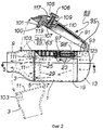
на фиг. 2 показан перспективный вид сбоку варианта реализации с фиг. 1, с ручкой дозирующего инъектора, поднятой из закрепленного положения переноски, и с опущенной вниз, для того чтобы открыть внутреннюю полость устройства, передней частью;
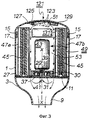
на фиг. 3 - вид сверху в разрезе предпочтительного варианта реализации, выполненный по линии 3-3 на фиг. 2;
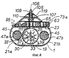
на фиг. 4 - вид спереди в разрезе, выполненный по линии 4-4 на фиг. 3 и показывающий распылительную камеру и крыльчатку при отсутствии соосности между ними;
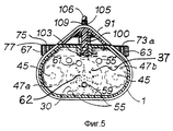
на фиг. 5 показан еще один вид спереди в разрезе, выполненный по линии 5-5 на фиг. 3, проходящий перед задней стенкой переднего мундштука, демонстрирующий предпочтительно расположение отверстий для поступления воздуха;
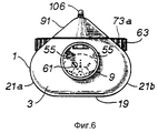
на фиг. 6 - вид с переднего торца варианта реализации, показанного на фиг. 1;
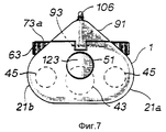
на фиг. 7 - вид с заднего торца варианта реализации, показанного на фиг. 1;
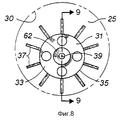
на фиг. 8 показано крупным планом изображение распылительной камеры с крыльчаткой при отсутствии соосности между ними;
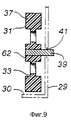
на фиг. 9 - вид сбоку в разрезе крыльчатки, изображенной на фиг. 8;
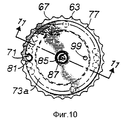
на фиг. 10 - вид сверху кассеты с дозами в сборе, применяемой в варианте реализации, показанной на фиг. 1;
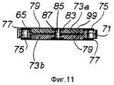
на фиг. 11 - вид сбоку кассеты с дозами в разрезе, выполненном по линии 11-11 на фиг. 10;
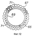
на фиг. 22 - вид сверху кольцевой части кассеты, на которой показаны отверстия для размещения доз лекарственного средства;
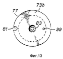
на фиг. 13 - вид сверху одной из крышек, показанных на фиг. 10;
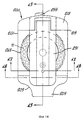
на фиг. 14 - вид сверху второго предпочтительного варианта реализации изобретения;
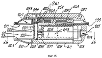
на фиг. 15 показано изображение в разрезе по линии 15-15 на фиг. 14;
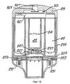
на фиг. 16 - изображение в разрезе по линии 16-16 на фиг. 14;
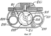
на фиг. 17 - изображение в разрезе по линии 17-17 на фиг. 14;
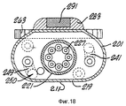
на фиг. 18 - изображение в разрезе по линии 19-18 на фиг. 14;
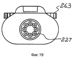
на фиг. 19 - вид с переднего торца варианта реализации, показанного на фиг. 14;
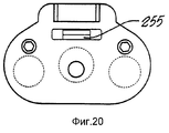
на фиг. 20 - вид с заднего торца варианта реализации, показанного на фиг. 14;
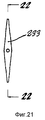
на фиг. 21 показан увеличенный вид спереди крыльчатки варианта реализации с фиг.14;
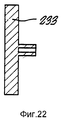
на фиг. 22 - вид в разрезе по линии 22-22 на фиг. 21;
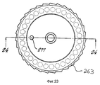
на фиг. 23 - вид сверху кассеты с дозами в сборе, применяемой в варианте реализации, показанной на фиг. 14;
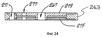
на фиг. 24 - вид в разрезе по линии 24-24 на фиг. 23;
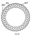
на фиг. 25 - вид сверху кольцевой части кассеты с фиг. 23, на которой показаны отверстия для размещения доз сухого порошка;
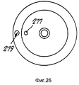
на фиг. 26 - вид сверху кассеты в сборе с фиг. 23, включая верхнюю крышку;
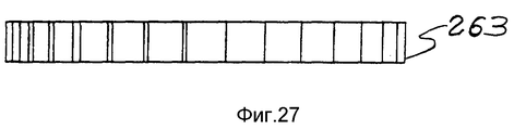
на фиг. 27 - вид сбоку кольцевой части с фиг. 25;
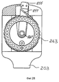
на фиг. 28 показан вид сверху ингалятора с фиг. 14 с откинутым или снятым прижимным рычагом и снятыми крышками кассеты, что сделано только в целях наглядности;
на фиг. 29 - вид сбоку ингалятора с фиг. 14 с изображением движения прижимного рычага;
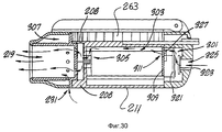
на фиг. 30 - вид сбоку, частично в разрезе, ингалятора с фиг. 14, схематически иллюстрирующий направления прохождения воздуха через него;
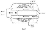
на фиг. 31 - то же, вид сверху;
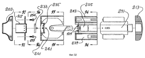
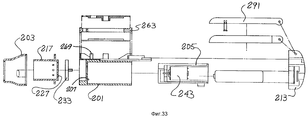
на фиг. 32 - вид сверху с разделением на детали ингалятора с фиг. 14;
на фиг. 33 - то же, вид сбоку, частично в разрезе;
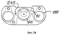
на фиг. 34 - вид с торца шасси двигателя, выполненный по линии 34-34 на фиг. 32;
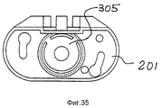
на фиг. 35 - вид с торца кожуха по линии 35-35 на фиг. 32;
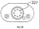
на фиг. 36 - вид с заднего торца переднего цилиндра по линии 36-36 на фиг. 32;
на фиг. 37 показан его вид с переднего торца по линии 37-37 на фиг. 32.In the drawings, the same reference numbers indicate the same elements shown from different positions:
in FIG. 1 is a plan view of a preferred embodiment of the invention;
in FIG. 2 shows a perspective side view of the embodiment of FIG. 1, with the handle of the metering injector raised from the fixed position of the carrying, and lowered down, in order to open the internal cavity of the device, the front part;
in FIG. 3 is a sectional plan view of a preferred embodiment taken along line 3-3 of FIG. 2;
in FIG. 4 is a sectional front view taken along line 4-4 of FIG. 3 and showing the spray chamber and the impeller in the absence of alignment between them;
in FIG. 5 shows yet another cross-sectional front view taken along line 5-5 of FIG. 3 extending in front of the rear wall of the front mouthpiece, preferably showing the location of the air inlet openings;
in FIG. 6 is a front view of the embodiment shown in FIG. 1;
in FIG. 7 is a rear view of the embodiment shown in FIG. 1;
in FIG. 8 is a close-up view of a spray chamber with an impeller in the absence of alignment between them;
in FIG. 9 is a sectional side view of the impeller of FIG. eight;
in FIG. 10 is a plan view of the complete dose cartridge used in the embodiment of FIG. 1;
in FIG. 11 is a side view of a sectional dose cassette taken along line 11-11 of FIG. ten;
in FIG. 22 is a top view of the annular part of the cartridge, which shows the holes for placing doses of the drug;
in FIG. 13 is a plan view of one of the caps shown in FIG. ten;
in FIG. 14 is a plan view of a second preferred embodiment of the invention;
in FIG. 15 is a sectional view taken along line 15-15 of FIG. fourteen;
in FIG. 16 is a sectional view taken along line 16-16 of FIG. fourteen;
in FIG. 17 is a sectional view taken along line 17-17 of FIG. fourteen;
in FIG. 18 is a sectional view taken along line 19-18 of FIG. fourteen;
in FIG. 19 is a front view of the embodiment shown in FIG. fourteen;
in FIG. 20 is a rear view of the embodiment shown in FIG. fourteen;
in FIG. 21 is an enlarged front view of the impeller of the embodiment of FIG. 14;
in FIG. 22 is a sectional view taken along line 22-22 of FIG. 21;
in FIG. 23 is a plan view of the complete dose cartridge used in the embodiment of FIG. fourteen;
in FIG. 24 is a sectional view taken along line 24-24 of FIG. 23;
in FIG. 25 is a plan view of the annular portion of the cartridge of FIG. 23, which shows openings for placing doses of dry powder;
in FIG. 26 is a top view of the cartridge assembly of FIG. 23, including the top cover;
in FIG. 27 is a side view of the annular portion of FIG. 25;
in FIG. 28 is a plan view of the inhaler of FIG. 14 with the clamping lever folded out or removed and the cassette covers removed, which is done for illustrative purposes only;
in FIG. 29 is a side view of the inhaler of FIG. 14 depicting the movement of the pressure lever;
in FIG. 30 is a side view, partially in section, of the inhaler of FIG. 14 schematically illustrating the directions of air passing through it;
in FIG. 31 - same, top view;
in FIG. 32 is a plan view, divided into parts of the inhaler of FIG. fourteen;
in FIG. 33 is the same, side view, partially in section;
in FIG. 34 is an end view of an engine chassis taken along line 34-34 of FIG. 32;
in FIG. 35 is an end view of the casing along line 35-35 of FIG. 32;
in FIG. 36 is a view from the rear end of the front cylinder along line 36-36 of FIG. 32;
in FIG. 37 shows a front view thereof along line 37-37 of FIG. 32.
На фиг. 1-3 показан общий вид первого предпочтительного варианта реализации, в котором полая передняя часть 3 шарнирно закреплена на внутренней поверхности средней части 1 на двух ушках 5. Два штифта 7 закреплены своими концами в средней части 1, чтобы откидывать деталь 3 наружу и вниз относительно средней части 1. Передняя часть 3 включает полый трубчатый мундштук 9, предназначенный для ввода в рот или нос и выполненный на передней конце передней части, в то время как задняя стенка 11 закрывает переднюю часть 3 сзади. Задняя часть 13 крепится к средней части 1 по кромке 15 с помощью зажимной юбки 17 или другого известного приспособления. Средняя часть 7 обычно состоит из плоской донной части 19, двух разнесенных между собой закругленных стенок 21a и 21b и диска 23 с упрощенной поверхностью для удобства захвата пользователем. In FIG. 1-3, a general view of the first preferred embodiment is shown, in which the hollow
Как показано на фиг. 2, 3, 4 и 8, в передней стенке 27 средней части 1 выполнена дисковидная или круглая распылительная камера 25, расположенная поперек направления потока воздуха, показанного стрелками на фиг. 2 и 3 существующего мундштука 9. Камера 25 имеет форму диска, предпочтительно диаметром порядка 13 мм и толщиной 3 мм, при отношении диаметра камеры к толщине (или глубине) камеры предпочтительно приблизительно 4:1. Камера 25 ограничена спереди частью задней изолирующей стенки 11, сзади гладкой стенкой 29 и по периферии круговой стенкой 30. As shown in FIG. 2, 3, 4 and 8, in the
Крыльчатка 31, показанная на фиг. 3, 4, 8 и 9, состоит из тонкой, плоской круглой пластины 33 с периферийной кромкой 35. От периферийной кромки 35 наружу в радиальном направлении отходит множество коротких лопастей 37. Пластина 33 расположена в камере 25 со смещением от центра или эксцентрично. Как показано на фиг. 4 и 5, крыльчатка 31 расположена ниже геометрического центра распылительной камеры 25, будучи смещена в направлении нижней части круговой стенки 30. Передняя поверхность крыльчатки расположена очень близко к задней стенке 11. Крыльчатка 31 установлена на центральном валу 39, который проходит через отверстие 41, выполненное в задней стенке камеры 39, и предназначена для быстрого вращения от привода вокруг постоянной оси Х-Х, показанной на фиг. 3. Вал 39 соединен с высокооборотным электродвигателем 43, питание которого осуществляется от по меньшей мере одной, но предпочтительно от двух батареек 45. Батарейки 45 помещены в отдельно расположенных гнездах 47a и 47b. Распылительную камеру 25 можно открыть для целей очистки и технического обслуживания, повернув переднюю часть 3 относительно штифтов 7, как показано на фиг. 2. The
Камера или воздушный канал 49, показанный на фиг. 3, 5 и 7, пропускает дросселированную струю воздуха через полость средней части 1 в направлении мундштука 9 для вдыхания пользователем. Камера 49 состоит из по меньшей мере одного отверстия 51, выполненного в задней части 13 для поступления наружного воздуха в среднюю часть 1. Во внутренней полости средней части 1 выполнены пропускные каналы 53, сообщающиеся с отверстием 51, которые пропускают струю воздуха, показанную стрелками на фиг. 2 и 3, через среднюю часть 1 в направлении мундштука 9. Каналы выходят в полую переднюю часть 3 через по меньшей мере одно, но предпочтительно множество дросселирующих отверстий 55, выполненных в заданной стенке 11, как показано на фиг. 5. Размеры отверстия 51, каналов 53 и отверстий 55 подобраны таким образом, чтобы создавать значительное сопротивление воздушному потоку, регулировать скорость прохождения этого воздушного потока через среднюю часть 1 и в рот пользователя. Это, очевидно, уменьшает количество движения частиц и соответственно удары о заднюю поверхность горла пользователя. The chamber or
Часть основной струи воздуха отклоняется, как показано стрелками на фиг. 2 и 3, для пропуска через распылительную камеру 25 и выноса лекарственного порошка в основную струю воздуха. Этого достигают с помощью впускного отверстия 59, выполненного в задней замыкающей стенке 11 рядом с центром крыльчатки 31. Выпускное отверстие 61 выполнено в задней замыкающей стенке 11 в верхней части распылительной камеры 25. В то время как электродвигатель 43 вращает крыльчатку 31 с большой скоростью, крыльчатка действует как центробежный воздушный насос, всасывающий воздух через впускное отверстие 59, смешивает в камере 25 воздух с полной дозой лекарственного средства в форме порошка и выбрасывает воздух и лекарственное средство в форме тонкого, обладающего низкой плотностью сухого аэрозоля через выпускное отверстие 62. Этот несущий порошок воздух или аэрозоль объединяется затем с основной дросселирующей струей воздуха в мундштуке 9 для вдыхания пользователем. Размеры отверстий 59 и 61 подобраны таким образом, что аэрозоль выходит из камеры 25 через отверстие 61 с пренебрежимо малой с клинической точки зрения скоростью. Размеры впускного отверстия 59 могут быть установлены, например, равными 2,4 мм в диаметре, а размеры выпускного отверстия 61 могут быть установлены, например, равными 1,6 мм в диаметре. Эта низкая скорость в сочетании с первой дросселирующей воздушной струей позволяет получить тонкую, обладающую низкой плотностью аэрозоль, легко вдыхаемую пользователем без принудительной ингаляции. Поскольку больше не требуется прошивания капсулы или использования вакуума или центробежных сил для извлечения лекарственного средства капсулы, пользователем больше не нужно прилагать усилия для втягивания лекарственного средства в легкие. Part of the main air stream is deflected, as shown by the arrows in FIG. 2 and 3, for passing through the
Крыльчатка 31 вращается электродвигателем 43 с чрезвычайно высокой скоростью, достигаемой 12000-14000 об/мин. Такая высокая скорость ведет к высокой скорости потока и турбулентности порошка в струе воздуха и за счет неравномерности этого потока, связанной с эксцентричностью расположения крыльчатки 31, вызывает столкновения частиц между собой и со стенками камеры 11, 29 и 30, что ведет к их дроблению и разделению на более мелкие, более пригодные для дыхания частиц. Кроме того, это явление ведет к более тесному перемешиванию частиц с воздушным потоком, что ведет к возникновению самоочищающего эффекта на стенках камеры. Из-за эксцентричности расположения крыльчатки 31 в камере 25 высокоскоростная циркуляция воздуха происходит при различном давлении и скорости в различных точках камеры 25. Это явление обеспечивает турбулентное перемешивание частиц и воздуха и уменьшает спекание лекарственного порошка. Как показано на фиг. 5, впускное отверстие 59 может быть расположено в обширной области ниже бобышки крыльчатки 62, но предпочтительно оно располагается непосредственно под бобышкой крыльчатки 62 и над лопастями 37, чтобы обеспечить менее ограниченный выход в камеру 25. Аналогичным образом выпускное отверстие 61 может быть распложено практически в любом месте над бобышкой крыльчатки 62, но предпочтительным является его размещение над лопастями 37 и с одной или с другой стороны осевой линии камеры 25. В случае, если пользователь попытается вдохнуть или втянуть воздух через мундштук 9 с большой интенсивностью, во внутренней полости средней части 1 образуется низкий вакуум, однако этот вакуум должен существовать по всему внутреннему объему средней части 1, так что вакуум или интенсивность, с которой пользователь вдыхает или втягивает воздух через мундштук 5, не должна оказать влияния на центробежное перекачивающее действие эксцентричной крыльчатки 31. The
На фиг. 10-12 показана содержащая много доз лекарственного средства кассета 63, предназначенная для использования в варианте реализации, показанном на фиг. 1. Как показано на фиг. 12, кассета 63 состоит из относительно тонкого кольца 65 из пластмассы или иного легкого материла с гребенчатой наружной кромкой 67 и гладкой внутренней кромкой 69. По кольцу 65 между наружной кромкой 67 и внутренней кромкой 69 размещен ряд отверстий 71, предназначенных для размещения доз лекарственного средства. Обе стороны кольца 65, как показано на фиг. 10 и 11, закрывают две крышки 73a и 73b с тонким наружным фланцем 75 и внешней кромкой 77 и более толстой внутренней частью 79. Во фланце 75 каждой крышки выполнен U-образный вырез 81. Крышки скреплены вместе, как показано на фиг. 11, зажимая кольцо 65 между собой. Внешняя кромка 77 несколько не достигает до гребенчатой наружной кромки 67 кольца, как показано на фиг. 10. U-образные вырезы 81 в крышках 73a и 73 расположены одно над другим, как показано на фиг. 10, так что доза лекарственного средства, расположенная в каждом отверстии, открывается по одной по мере вращения кольца 65 между крышками 73a и 73b. Рядом с центральным отверстием 85 в крышках 73a и 73b выполнено центральное углубление 83. В отверстие вставлена полая заклепка 87 или иное крепежное изделие, скрепляющее крышки 73a и 73b над кольцом 65. In FIG. 10-12 show a
Предусмотрен установочный механизм 89 для установки дозирующей кассеты 63 на среднюю часть 1 и для подачи лекарственного средства в распылительную камеру 25. Установочный механизм 89, как показано на фиг. 1 и 2, состоит из прижимного рычага 91, поворачивающегося на штифте 93, установленном на задней части 13. На верхней поверхности средней части 23 выполнен открытый участок 95 для размещения дозирующей кассеты 63 на центральном штифте 97. Сдвинутый относительно центра штифт 98 входит в небольшое сквозное отверстие 99, выполненное в крышках 73a и 73b, делая их неподвижными. Крепежная стойка 100, включающая подпружиненную шаровую защелку 101, выступает в переднем конце прижимного рычага 91 и приспособлена для ввода в приемное отверстие 103, выполненное с обратной стороны передней части 3. A mounting
Плунжер 105 для загрузки лекарственного средства с T-образным верхним стержнем 106 установлен с возможностью возвратно-поступательных движений в канале 107 прижимного рычага 91 и прижимается пружиной 109 вверх, к упору 110, выполненному в плунжере 105. Желоб для подачи лекарственного средства 111 выполнен в средней части 1 ниже плунжера 105 и простирается вниз к верхней части распылительной камеры 25. Диаметр желоба 111 предпочтительно совпадает с диаметром отверстия 71. The
В процессе использования дозирующую кассету 63 устанавливают на открытом участке 95 на штифты 97 и 98. Прижимной рычаг 91 опускают для удержания кассеты и фиксации мундштука 9 в рабочем закрытом положении. U-образные вырезы 81 и крышках 73a и 73b автоматически совмещают ниже плунжера 105 для загрузки лекарственного средства путем совмещения отверстия 99 и сдвинутого штифта 98. Выпускное отверстие 61 распылительной камеры предпочтительно располагается несколько в стороне от желоба 111, чтобы не допустить помех загрузке лекарственного средства или засорения выпускного отверстия 61 лекарственным средством в процессе загрузки. In use, the dispensing
Подпружиненный шарик 113, показанный на фиг. 1, выполнен в задней части 13 таким образом, чтобы этот шарик прижимался к гребенчатой наружной кромке 67, не допуская нежелательного движения кольца 65 дозирующей кассеты. Затем кольцо 65 поворачивается, чтобы совместить заполненное лекарственным средством отверстие 71 с желобом 111. Преодолевая сопротивление пружины 109, нажимают на загрузочный плунжер 105, выдавливая полную дозу лекарственного порошка непосредственно в распылительную камеру 25. После этого плунжер 105 остается в желобе 111, образуя верхнюю часть круговой стенки 30 распылительной камеры 25. Плунжер 105 можно удерживать в этом положении, преодолевая противодействие пружины, повернув ручку плунжера 106 и зафиксировав ее под лепестками 117, выступающими над полостью 119, выполненной в передней части прижимного рычага 91, как показано на фиг. 1. The spring ball 113 shown in FIG. 1, is made in the
Предлагается предупреждающая выдыхание система 121, не допускающая попадания в устройство выдыхаемого пациентом воздуха, так чтобы содержащаяся в выдохе влага не способствовала слипанию порошка. Предупредительная система 121 состоит из однопутевого клапана 123 или заслонки, шарнирно закрепленной штифтом 125 в отверстии 51 в задней части устройства 13. Пружина 127 соединена с заслонкой, удерживая ее в закрытом положении на отверстии 51 в течение всех манипуляций с устройством, за исключением момента, когда пользователь втягивает воздух через мундштук 9. Когда пользователь вдыхает или втягивает воздух через среднюю часть 1, снижение внутреннего давления в средней части 1 ведет к тому, что атмосферное давление, действующее на заслонку 123, преодолевает противодействие пружины 127 и открывает ее, пропуская воздух во внутреннюю полость средней части 1 и создавая первую струю воздуха, как описано выше. Переключать с нормально разомкнутыми контактами 129 соединен с заслонкой 123 и взаимосвязан с электродвигателем 43 и батарейками 45 через электрическую обойму 131, выполненную в средней части 1, гарантируя, что питание двигателя 43 от батареек 45 не будет иметь места, пока не откроется заслонка 123. Заслонка 123 откроется, когда пользователь втягивает воздух через мундштук 9, чтобы вдохнуть распыленный лекарственный порошок. An
Объем многих лекарственных средств, в соответствии с их дозированием, часто чрезвычайно мал. В течение многих лет существует практика разведения этих объемов инертными материалами-заполнителями в целях увеличения суммарного объема до размеров, удобных в обращении, как в случае с таблетками аспирина и тому подобными. Аналогичным образом и в случае с вдыхаемыми лекарственными порошками существует установившаяся практика добавления к лекарственному средству инертных порошков, чтобы довести их объем до размеров, пригодных для эффективного вдыхания. The volume of many drugs, in accordance with their dosage, is often extremely small. For many years, there has been the practice of diluting these volumes with inert filler materials in order to increase the total volume to sizes that are easy to handle, as is the case with aspirin tablets and the like. Similarly, in the case of inhaled medicinal powders, there is a well-established practice of adding inert powders to the medicinal product in order to bring their volume to sizes suitable for effective inhalation.
Однако при этом, видимо, уделяли мало или совсем не уделяли внимания размерам частиц инертного порошка в связи с проблемой момента движения крупных частиц и нарастания спекшейся массы. В настоящее время обнаружено, что смешивание определенного количества тщательно контролируемых по размерам, более крупных частиц инертного порошка с практически любой дозой тонкоизмельченного активного ингредиента или лекарственного порошка позволит получить полезную смесь размеров частиц, которые будут перемешиваться или подвергаться измельчению и самоочистке в распылительной камере. В этой смеси порошок распадается и измельчается до частиц небольших размеров, которые выносятся из распылительной камеры в первую очередь, в то время как более крупные частицы инертного материала осуществляют очистку внутренних поверхностей распылительной камеры. Более крупные частицы подвергаются далее самоизмельчению и самоочистке для вдыхания пользователем. В связи с низкой скоростью потока воздуха, проходящего через мундштук, что связано с дросселированием в канале 49, очевидно, что любым крупным частицам придается в целом недостаточный момент движения, чтобы происходило соударение с мягкой влажной тканью горла и гортани. В соответствии с этим применение разбавителя в форме частиц нетоксичного вещества, такого как лактоза, причем значительная их часть имеет размеры диаметром 50 мкм и более, позволяет удалять из распылительной камеры лекарственное средство, состоящее из более мелких частиц, несмотря на первоначальную влажность лекарственного средства. However, at the same time, apparently, they paid little or no attention to the particle sizes of the inert powder in connection with the problem of the moment of movement of large particles and the growth of sintered mass. It has now been found that mixing a certain amount of carefully controlled, larger particles of inert powder with virtually any dose of the finely divided active ingredient or drug powder will provide a useful mixture of particle sizes that will be mixed or subjected to grinding and self-cleaning in a spray chamber. In this mixture, the powder disintegrates and is crushed to particles of small sizes, which are primarily removed from the spray chamber, while larger particles of inert material clean the inner surfaces of the spray chamber. Larger particles are further self-grinding and self-cleaning for inhalation by the user. Due to the low flow rate of air passing through the mouthpiece, which is associated with throttling in
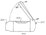
Второй вариант реализации предлагаемого ингалятора 200 показан на фиг. 14 - 37. Как можно видеть на фиг. 14 и 15, ингалятор 200 состоит из средней части или корпуса 201. Передняя часть 203 корпуса 201 сходит на конус, образуя мундштук 209, диаметр которого позволяет пользователю без труда взять его в рот. Корпус 201 имеет плоскую нижнюю поверхность 211. Задняя часть прикреплена к задней стороне корпуса 201. Кассета 263 с лекарственным порошком установлена на оси сверху корпуса 201, причем на кассете 263 лежит прижимной рычаг 291. A second embodiment of the
На фиг. 15 показан передний цилиндр 217 с цилиндрическими стенками 221 и задней пластиной 225, образующими переднюю камеру 219. Фланец 223 выступает в радиальном направлении наружу от цилиндрических стенок 221 непосредственно перед задней пластиной 225. В задней пластине 225 выполнены конические выпускные отверстия 227 со скошенной или заостренной кромкой. Выпускные отверстия 227 предпочтительно располагаются по схеме, показанной на фиг. 37. Радиальные отверстия 229 выполнены в цилиндрических стенках 221 переднего цилиндра 217, соединяя его полость с передней камерой 219 непосредственно перед выпускными отверстиями 227. Предпочтительно, чтобы радиальные отверстия 229 располагались на цилиндрических стенках 221 на одинаковом расстоянии друг от друга. От верхней поверхности корпуса 201 в камеру крыльчатки 235 опущен желоб для порошка 261. Переднее впускное отверстие для воздуха 231 выполнено в наружной стенке передней части 203 и открывается в распределительную камеру 307, образованную между передней частью 203 и передним цилиндром 217. In FIG. 15 shows a
На фиг. 15, 16 и 17 показано шасси 205 электродвигателя, закрепленное в корпусе 201. Шасси двигателя 205 имеет два боковых гнезда 239 для батареек, соединенные с центральным гнездом для двигателя перемычками 245, показанными на фиг. 34. В заднем конце шасси двигателя 205 выполнена разделительная стенка 309 с отверстием для подачи воздуха 311. In FIG. 15, 16 and 17 show the
В переднем конце гнезда 241 для двигателя, как показано на фиг. 16, помещен высокооборотный миниатюрный электродвигатель 243. Вал двигателя 237 выступает из двигателя 243 через отверстие для вала в передней стенке 247 гнезда для двигателя 241 в камеру крыльчатки 235. На валу двигателя 237 установлена крыльчатка 233, вращающаяся в камере крыльчатки 235. Как показано на фиг. 21 и 22, крыльчатка имеет два противоположных крыла в форме призмы, образующих равносторонний параллелограмм. At the front end of the
Камера крыльчатки 235 образована передней стенкой 207 корпуса 201, передней кромкой 208 корпуса вокруг передней стенки 207 и задней пластиной 225 переднего цилиндра, хотя возможны и иные конфигурации. Камера крыльчатки 235, как показано на фиг. 15 и 16, является открытым пространством, в общем, дисковидной формы. Крыльчатка 233 вставлена в камеру крыльчатки 235 с минимальным зазором (предпочтительно около 0,2 - 0,3 мм) как спереди, так и сзади, т.е. между задней пластиной 225 и передней стенкой 207 корпуса, а также в радиальном направлении, при длине и диаметре крыльчатки 233, лишь немногим меньших диаметра кромки 208. Такое относительно плотное размещение крыльчатки в камере обеспечивает должное взаимодействие воздуха и лекарственного порошка в процессе перемешивания. В отличие от первого варианта реализации крыльчатка 233 расположена по центру камеры 235. The
Как показано на фиг. 16 и 32, передняя часть 203 снабжена резьбовыми бобышками 251 по сторонам мундштука 209. Передний цилиндр 217 крепится к передней части 203 болтами 253, пропущенными через отверстия во фланце 223 и ввинченными в бобышки 251. Болты 253 имеют головки с буртиком 254, выступающие в установочные пазы 249 в корпусе 201, как показано на фиг. 18. Переднюю часть 203 и передний цилиндр 217 можно прикрепить к корпусу 201, вставив головки с буртиков 254 в отверстия 250 в пазах 249 и поворачивая переднюю часть 203 под острым углом. Выполнение этих операций в обратной последовательности позволяет снять указанные детали для получения доступа в камеру крыльчатки 235. As shown in FIG. 16 and 32, the
Кассета 263, установленная сверху на корпус 201, состоит из кольца кассеты 164 с пилообразной кромкой 265, как показано на фиг. 25. Отверстия 271, размещенные по длине кольца кассеты 264, заполнены (напр. на фабрике или в аптеке) сухим порошком лекарственного средства. Сверху и снизу на кольце кассеты 264 установлены верхняя крышка 273 и нижняя крышка 275, образуя кассету 263 в сборе и не допуская утечку или загрязнение порошка в отверстиях 271, как показано на фиг. 23, 24 и 26. Заклепка или иное крепежное изделие удерживает верхнюю и нижнюю крышки на кольце кассеты 264. В верхней и нижней крышках 273 и 275 выполнены препятствующие вращению совмещаемые отверстия 227. Отверстие для желоба 279 в верхней крышке 273 и нижней крышке 275 выполнено таким образом, чтобы к отверстиям 271 открывался доступ при их совмещении с желобом 279. The
Как показано на фиг. 14, 15, 28 и 29, кассету устанавливают на корпус 201 с осью 259, выступающей из корпуса вверх в центральное отверстие 267 кассеты 163. Шпенек 269, также выступающий вверх из корпуса 201, проходит через шпеньковые отверстия 277 в верхней крышке 273 и нижней крышке 275, не позволяя крышкам поворачиваться вместе с кольцом кассеты 264. На фиг. 28 показано, как пружина 257 храпового механизма на опоре храпового механизма 255 корпуса 201 упирается в выступы 265 по периметру кольца 264 кассеты, так что кольцо кассеты может вращаться только в одном направлении (т.е. по часовой стрелке, как показано на фиг. 28). As shown in FIG. 14, 15, 28 and 29, the cartridge is mounted on the
Рычажная рама 283 установлена с возможностью вращения на задней части 213 на оси вращения 287. Защелка 293 скрепляет с возможностью освобождения передний конец рычажной рамы 283 с передней частью Прижимной рычаг 291, размещенный в рычажной раме 283, также закреплен на оси вращения 287. Плунжер 289 прикреплен с возможностью вращения штифтом 285 к прижимному рычагу 291. Плунжер 289 совмещен с желобом для порошка 261. The
На фиг. 30 и 31 показано впускное отверстие 325, выполненное в задней части 213. Однопутевой клапан 323 отделяет впускное отверстие 325 от полости 308 задней части 213. Соединительная монтажная плата 321 расположена поперек задней части 213. Задняя полость 301 соединяется со средней полостью 303 отверстием для подачи воздуха 311 в разделительной стенке 309. Две средние полости 303 ведут вперед в корпусе 201 до двух прорезей 305 в передней стенке 207, ведущих к камере крыльчатки 235. Переключатель 329 на однопутевом клапане 323 электрически связан с двигателем 43 и батарейками 45 через монтажную схему 321, чтобы включать двигатель, когда открывается однопутевой клапан. In FIG. 30 and 31, an
В процессе применения кассету 263 устанавливают на ингалятор 200, поворачивая рычажную раму 283 и удерживая прижимной рычаг 291 в верхнем положении, как показано на фиг. 29. Кассету 263 устанавливают на ось 259 со шпеньком 269, проходящим через шпеньковые отверстия 277 в верхней и нижней крышках кассеты 263. Рычажную раму 283 поворачивают назад к корпусу 201, а прижимной рычаг 291 опускают, совместив плунжер 289 с отверстием 271 в кассете 263. После прижатия прижимного рычага 291 плунжер 289 выталкивает лекарственный порошок из отверстия 271 по желобу 261 и в камеру крыльчатки 235. Размеры плунжера 289 точно совпадают с диаметром отверстий 271, чтобы выталкивать из отверстия практически весь порошок. Плунжер 289 проходит также через весь желоб 261, так что вся доза из отверстия полностью проталкивается в камеру крыльчатки и на желобе 261 практически не остается порошка. Объем дозы, как показано на чертежах, очень мал по сравнению с объемом камеры крыльчатки. Теперь ингалятор 200 готов к использованию. In use, the
Мундштук 209 вставляют в рот пациента. Когда пользователь делает осторожный вдох, в передней камере 219 происходит небольшое понижение давления, что наблюдается также в соединенных между собой камере крыльчатки 235, средней полости 303 и задней полости 301. Понижение давления в задней полости 301 вызывает открывание однопутевого клапана 323, в результате чего замыкаются контакты переключателя 329 и включается электродвигатель 243. После включения двигателя и начала вращения крыльчатки 233 в камере крыльчатки 235 (которая заполнена теперь дозой лекарственного порошка) воздух поступает в ингалятор 200 из впускного отверстия 325 через заднюю полость 301, затем через отверстие для подачи воздуха 311 в среднюю полость 303, через каналы 305 и в камеру крыльчатки 235, как показано схематически на фиг. 30 и 31. Струя воздуха не допускает также попадания порошка в двигатель. The
Крыльчатка, вращающаяся со скоростью приблизительно 14000 об/мин, обеспечивает эффективное смешивание порошка с воздухом, протекающим через камеру крыльчатки. Как показано на фиг. 30 и 31, заполненный порошком воздух выходит из камеры крыльчатки 235 через выпускные отверстия 227 и в переднюю камеру 219. Обращенные к камере крыльчатки острые кромки выпускных отверстий 227 по существу не допускают нарастания порошка в отверстиях, предупреждая забивание. Наружный воздух поступает в распределительную камеру 307 через переднее воздушное впускное отверстие 231, размеры которого могут регулироваться с целью усиления или уменьшения воздушного потока для улучшения эффективности переноса. Из распределительной камеры 307 воздух проходит внутрь через радиально расположенные отверстия 229, которые ограничивают расход благодаря своей конструкции. Наружный воздух предназначен для образования в передней камере 219 граничного слоя для смешанного с порошком воздуха. Смешанный с порошком воздух, окруженный граничным слоем наружного воздуха, втягивается из передней камеры 219 в рот, горло и легкие пользователя с целью доставки лекарственного порошка. Граничный слой препятствует накоплению и сбору лекарственного порошка на внутренних стенках мундштука и способствует также, как полагают, предупреждению оседания порошка во рту и горле пользователя. Когда пользователь прекращает ингаляцию, клапан 323 закрывает отверстие, выключает переключатель 329 и останавливает двигатель. Таким образом, ингалятор приводится в действие дыханием. Поскольку клапан 323 открывается даже при небольшом перепаде давления, для включения ингалятора требуется лишь небольшой вдох. An impeller rotating at a speed of approximately 14,000 rpm provides effective mixing of the powder with air flowing through the impeller chamber. As shown in FIG. 30 and 31, the air filled with powder exits the
Ингалятор 200, как и ингалятор, показанный на фиг. 1, образует медленно перемещающийся аэрозоль из тонкоизмельченного порошка, который можно безопасно и легко вдохнуть глубоко в легкие, чтобы максимизировать фактически доставленную дозу и действие лекарственного средства. В отличие от многих ингаляторов, применяющихся до сих пор, настоящий ингалятор не требует слишком сильного или глубокого вдоха для обеспечения доставки лекарственного средства. В соответствии с этим функции легких пользователя совсем не так важны, как в случае прежних решений. Поэтому настоящий ингалятор особенно подходит для лиц с нарушениями работы легких.
Кроме того, выдыхание в ингаляторе 200 предупреждается, поскольку однопутевой клапан 323 закрывается уже при небольшом повышении в задней полости 301. Если пользователь кашляет или дышит в ингалятор 200, часть увлажненного выдыхаемого воздуха пройдет через переднее впускное отверстие 231, но не достигнет в заметной степени камеры крыльчатки, не допуская повторного или избыточного выдыхания в ингалятор. In addition, exhalation in the
Настоящий ингалятор может иметь различные конструкционные особенности, основанные на признании того факта, что различные лекарственные средства в форме порошка имеют различные характеристики. Смеси лекарственных средств в форме порошков имеют варьирующиеся размеры и распределение частиц, плотность, слипаемость (тенденцию частиц лекарственного средства к слипанию друг с другом), адгезивность (тенденцию частиц лекарственного средства к налипанию на поверхность ингалятора). Таким образом, для повышения эффективности доставки можно удачно регулировать параметры расхода в ингаляторе в зависимости от конкретного вводимого лекарственного средства. Такую регулировку можно осуществлять путем регулирования скорости вращения крыльчатки 233 и путем варьирования расхода воздуха в камере крыльчатки. Расход воздуха в камере крыльчатки можно контролировать с помощью отверстия со скользящим диском 327, увеличивающим или уменьшающим размеры отверстия для подачи воздуха 311. С другой стороны, отверстие для подачи воздуха 311 можно пробить или рассверлить до определенных размеров, предназначенных для данного лекарственного средства. Следовательно, ингалятор удачно снабжен цепью установки или регулирования скорости вращения двигателя при размерах отверстия для регулирования расхода воздуха или отверстия для подачи воздуха, соответствующих характеристикам лекарственного средства, которое будет доставлять ингалятор. A true inhaler may have various design features based on the recognition that different drugs in powder form have different characteristics. Mixtures of pharmaceutical preparations in the form of powders have varying particle sizes and distributions, density, cohesion (the tendency of the drug particles to stick together), adhesiveness (the tendency of the drug particles to stick to the surface of the inhaler). Thus, to increase the delivery efficiency, it is possible to successfully control the flow rate in the inhaler, depending on the particular drug being administered. Such adjustment can be done by adjusting the speed of rotation of the
Электрические соединения на этих чертежах не показаны для ясности, поскольку такие соединения уже известны для предшествующих решений. На чертежах показаны предпочтительные размеры деталей ингалятора. The electrical connections in these figures are not shown for clarity, since such connections are already known in the prior art. The drawings show the preferred dimensions of the parts of the inhaler.
Электрические соединения на этих чертежах не показаны для ясности, поскольку такие соединения уже известны для предшествующих решений. На чертежах показаны предпочтительные размеры ингалятора. The electrical connections in these figures are not shown for clarity, since such connections are already known in the prior art. The drawings show preferred inhaler sizes.
В то время как изобретение описано на конкретных примерах реализации, специалисты в данной области могли бы внести различные изменения в описанные варианты без отступления от существа и объема изобретения. Специалистам в данной области также ясно, что различные детали, описанные в связи с одним вариантом реализации, могут быть использованы отдельно или в сочетании с любым вариантом реализации. While the invention has been described with specific implementation examples, those skilled in the art could make various changes to the described embodiments without departing from the spirit and scope of the invention. It will also be apparent to those skilled in the art that the various details described in connection with one embodiment may be used alone or in combination with any embodiment.
Claims (11)
Applications Claiming Priority (4)
| Application Number | Priority Date | Filing Date | Title |
|---|---|---|---|
| US96340992A | 1992-10-19 | 1992-10-19 | |
| US07/963,409 | 1992-10-19 | ||
| US07/963409 | 1992-10-19 | ||
| PCT/US1993/009751 WO1994008552A2 (en) | 1992-10-19 | 1993-10-12 | Dry powder inhaler |
Publications (2)
| Publication Number | Publication Date |
|---|---|
| RU95114532A RU95114532A (en) | 1997-07-27 |
| RU2141849C1 true RU2141849C1 (en) | 1999-11-27 |
Family
ID=25507205
Family Applications (1)
| Application Number | Title | Priority Date | Filing Date |
|---|---|---|---|
| RU95114532A RU2141849C1 (en) | 1992-10-19 | 1993-10-12 | Device for spraying of powder-like medicament |
Country Status (26)
| Country | Link |
|---|---|
| US (1) | US5577497A (en) |
| EP (1) | EP0665759B1 (en) |
| JP (1) | JP2912453B2 (en) |
| KR (1) | KR0177265B1 (en) |
| AT (1) | ATE174804T1 (en) |
| AU (1) | AU679700B2 (en) |
| BG (1) | BG61554B1 (en) |
| BR (1) | BR9307270A (en) |
| CA (1) | CA2147260C (en) |
| CZ (1) | CZ282964B6 (en) |
| DE (1) | DE69322789T2 (en) |
| DK (1) | DK0665759T3 (en) |
| ES (1) | ES2127837T3 (en) |
| FI (1) | FI951838A (en) |
| GR (1) | GR3029732T3 (en) |
| HK (1) | HK1013262A1 (en) |
| HU (1) | HU217917B (en) |
| NO (1) | NO311870B1 (en) |
| NZ (1) | NZ257056A (en) |
| PL (1) | PL172758B1 (en) |
| RO (1) | RO113214B1 (en) |
| RU (1) | RU2141849C1 (en) |
| SK (2) | SK279327B6 (en) |
| TW (1) | TW235245B (en) |
| UA (1) | UA27938C2 (en) |
| WO (1) | WO1994008552A2 (en) |
Cited By (1)
| Publication number | Priority date | Publication date | Assignee | Title |
|---|---|---|---|---|
| WO2011080761A1 (en) | 2009-12-30 | 2011-07-07 | Thirumalai Anadampillai Aparna | An improved dry powder inhaler |
Families Citing this family (213)
| Publication number | Priority date | Publication date | Assignee | Title |
|---|---|---|---|---|
| SK280967B6 (en) * | 1990-03-02 | 2000-10-09 | Glaxo Group Limited | Inhalation device |
| YU48707B (en) * | 1990-03-02 | 1999-07-28 | Glaxo Group Limited | Inhalation device |
| US6055980A (en) * | 1991-05-20 | 2000-05-02 | Dura Pharmaceuticals, Inc. | Dry powder inhaler |
| US5785049A (en) * | 1994-09-21 | 1998-07-28 | Inhale Therapeutic Systems | Method and apparatus for dispersion of dry powder medicaments |
| US6290991B1 (en) | 1994-12-02 | 2001-09-18 | Quandrant Holdings Cambridge Limited | Solid dose delivery vehicle and methods of making same |
| US6586006B2 (en) | 1994-08-04 | 2003-07-01 | Elan Drug Delivery Limited | Solid delivery systems for controlled release of molecules incorporated therein and methods of making same |
| JP3706136B2 (en) * | 1994-09-21 | 2005-10-12 | ネクター セラピューティクス | Apparatus and method for dispersing dry powder drug |
| US5780014A (en) * | 1995-04-14 | 1998-07-14 | Inhale Therapeutic Systems | Method and apparatus for pulmonary administration of dry powder alpha 1-antitrypsin |
| US5645051A (en) * | 1995-04-21 | 1997-07-08 | Dura Pharmaceuticals, Inc. | Unit dose dry powder inhaler |
| US5921237A (en) * | 1995-04-24 | 1999-07-13 | Dura Pharmaceuticals, Inc. | Dry powder inhaler |
| US5622166A (en) * | 1995-04-24 | 1997-04-22 | Dura Pharmaceuticals, Inc. | Dry powder inhaler delivery system |
| US6428771B1 (en) * | 1995-05-15 | 2002-08-06 | Pharmaceutical Discovery Corporation | Method for drug delivery to the pulmonary system |
| US5669973A (en) * | 1995-06-06 | 1997-09-23 | David Sarnoff Research Center, Inc. | Apparatus for electrostatically depositing and retaining materials upon a substrate |
| US5714007A (en) * | 1995-06-06 | 1998-02-03 | David Sarnoff Research Center, Inc. | Apparatus for electrostatically depositing a medicament powder upon predefined regions of a substrate |
| US20040237961A1 (en) * | 1995-06-08 | 2004-12-02 | Snow John Medlin | Inhalation actuated device for use with metered dose inhalers (MDIs) |
| US6672304B1 (en) | 1995-06-08 | 2004-01-06 | Innovative Devices, Llc | Inhalation actuated device for use with metered dose inhalers (MDIs) |
| DE19523516C1 (en) * | 1995-06-30 | 1996-10-31 | Asta Medica Ag | Inhaler for administering medication from blister packs |
| US5642727A (en) * | 1995-07-25 | 1997-07-01 | David Sarnoff Research Center, Inc. | Inhaler apparatus using a tribo-electric charging technique |
| US5875776A (en) * | 1996-04-09 | 1999-03-02 | Vivorx Pharmaceuticals, Inc. | Dry powder inhaler |
| BR9709748A (en) * | 1996-04-29 | 2000-01-11 | Dura Pharma Inc | Dry powder inhalation method |
| US5857456A (en) * | 1996-06-10 | 1999-01-12 | Sarnoff Corporation | Inhaler apparatus with an electronic means for enhanced release of dry powders |
| US5871010A (en) * | 1996-06-10 | 1999-02-16 | Sarnoff Corporation | Inhaler apparatus with modified surfaces for enhanced release of dry powders |
| US5794613A (en) * | 1997-01-09 | 1998-08-18 | Sepracor, Inc. | Multiple-dose dispenser for dry powder inhalers |
| TW469832U (en) | 1997-03-14 | 2001-12-21 | Astra Ab | Inhalation device |
| SE9700937D0 (en) * | 1997-03-14 | 1997-03-14 | Astra Ab | Powder inhales I |
| US6006747A (en) * | 1997-03-20 | 1999-12-28 | Dura Pharmaceuticals, Inc. | Dry powder inhaler |
| US20060165606A1 (en) | 1997-09-29 | 2006-07-27 | Nektar Therapeutics | Pulmonary delivery particles comprising water insoluble or crystalline active agents |
| NZ504021A (en) * | 1997-10-17 | 2003-04-29 | Systemic Pulmonary Delivery Lt | Method and apparatus for delivering aerosolized medication having air discharged through air tube directly into plume of aerosolized medication |
| US6237591B1 (en) | 1998-11-02 | 2001-05-29 | Dura Pharmaceuticals, Inc. | Turbine dry powder inhaler |
| ATE432727T1 (en) | 1997-12-02 | 2009-06-15 | Valois Sas | DRY POWDER INHALER |
| US6116238A (en) * | 1997-12-02 | 2000-09-12 | Dura Pharmaceuticals, Inc. | Dry powder inhaler |
| US6192876B1 (en) | 1997-12-12 | 2001-02-27 | Astra Aktiebolag | Inhalation apparatus and method |
| US6352722B1 (en) | 1997-12-23 | 2002-03-05 | Quadrant Holdings Cambridge Limited | Derivatized carbohydrates, compositions comprised thereof and methods of use thereof |
| US6004268A (en) * | 1998-04-21 | 1999-12-21 | Addington; W. Robert | Aspiration screening process for assessing post surgery patient's risk for pneumonia |
| US6257233B1 (en) | 1998-06-04 | 2001-07-10 | Inhale Therapeutic Systems | Dry powder dispersing apparatus and methods for their use |
| US6149774A (en) | 1998-06-10 | 2000-11-21 | Delsys Pharmaceutical Corporation | AC waveforms biasing for bead manipulating chucks |
| SE512386C2 (en) * | 1998-07-30 | 2000-03-06 | Microdrug Ag | Method and apparatus for classifying electrostatically charged powdery material |
| UA73924C2 (en) | 1998-10-09 | 2005-10-17 | Nektar Therapeutics | Device for delivering active agent formulation to lungs of human patient |
| FR2787031B1 (en) * | 1998-12-11 | 2001-03-30 | Valois Sa | IMPROVED INHALATION DEVICE |
| EP2191718A1 (en) | 1998-12-22 | 2010-06-02 | The University of North Carolina at Chapel Hill | Compounds and uses for the treatment of airway diseases and for the delivery of airway drugs |
| US6923979B2 (en) * | 1999-04-27 | 2005-08-02 | Microdose Technologies, Inc. | Method for depositing particles onto a substrate using an alternating electric field |
| US6444226B1 (en) * | 1999-06-29 | 2002-09-03 | Pharmaceutical Discovery Corporation | Purification and stabilization of peptide and protein pharmaceutical agents |
| US9006175B2 (en) | 1999-06-29 | 2015-04-14 | Mannkind Corporation | Potentiation of glucose elimination |
| US7464706B2 (en) | 1999-07-23 | 2008-12-16 | Mannkind Corporation | Unit dose cartridge and dry powder inhaler |
| US7305986B1 (en) * | 1999-07-23 | 2007-12-11 | Mannkind Corporation | Unit dose capsules for use in a dry powder inhaler |
| US6679256B2 (en) | 1999-12-17 | 2004-01-20 | Nektar Therapeutics | Systems and methods for extracting powders from receptacles |
| US6651655B1 (en) * | 2000-01-18 | 2003-11-25 | Quadrant Technologies Limited | Inhaled vaccines |
| ES2305057T3 (en) | 2000-02-28 | 2008-11-01 | Pharmakodex Limited | DEVICE FOR THE ADMINISTRATION OF ORAL PHARMACES. |
| US20030003057A1 (en) * | 2000-07-07 | 2003-01-02 | Jeffry Weers | Methods for administering leuprolide by inhalation |
| US8404217B2 (en) | 2000-05-10 | 2013-03-26 | Novartis Ag | Formulation for pulmonary administration of antifungal agents, and associated methods of manufacture and use |
| ES2525087T5 (en) | 2000-05-10 | 2018-06-28 | Novartis Ag | Phospholipid-based powders for drug administration |
| US7871598B1 (en) | 2000-05-10 | 2011-01-18 | Novartis Ag | Stable metal ion-lipid powdered pharmaceutical compositions for drug delivery and methods of use |
| US6948494B1 (en) | 2000-05-10 | 2005-09-27 | Innovative Devices, Llc. | Medicament container with same side airflow inlet and outlet and method of use |
| US20060083691A1 (en) * | 2000-05-10 | 2006-04-20 | Wermeling Daniel P | Intranasal opioid compositions, delivery devices and methods of using same |
| US6610271B2 (en) * | 2000-05-10 | 2003-08-26 | University Of Kentucky Research Foundation | System and method for intranasal administration of lorazepam |
| US20040115133A1 (en) * | 2000-05-10 | 2004-06-17 | Wermeling Daniel P. | Intranasal opioid compositions |
| TWI224515B (en) | 2000-06-23 | 2004-12-01 | Norton Healthcare Ltd | Pre-metered dose magazine for breath-actuated dry powder inhaler |
| US7288390B2 (en) | 2000-08-07 | 2007-10-30 | Centocor, Inc. | Anti-dual integrin antibodies, compositions, methods and uses |
| UA81743C2 (en) | 2000-08-07 | 2008-02-11 | Центокор, Инк. | HUMAN MONOCLONAL ANTIBODY WHICH SPECIFICALLY BINDS TUMOR NECROSIS FACTOR ALFA (TNFα), PHARMACEUTICAL MIXTURE CONTAINING THEREOF, AND METHOD FOR TREATING ARTHRITIS |
| US6902734B2 (en) | 2000-08-07 | 2005-06-07 | Centocor, Inc. | Anti-IL-12 antibodies and compositions thereof |
| AU2001283546A1 (en) | 2000-08-14 | 2002-02-25 | Advanced Inhalation Research, Inc. | Inhalation device and method |
| EP1315533A4 (en) * | 2000-08-15 | 2007-06-27 | Univ Kentucky Res Found | Programmable multi-dose intranasal drug delivery device |
| US20040176359A1 (en) * | 2001-02-20 | 2004-09-09 | University Of Kentucky Research Foundation | Intranasal Benzodiazepine compositions |
| US6766799B2 (en) | 2001-04-16 | 2004-07-27 | Advanced Inhalation Research, Inc. | Inhalation device |
| US7025058B2 (en) | 2001-04-26 | 2006-04-11 | New England Pharmaceuticals, Inc. | Metered dose delivery device for liquid and powder agents |
| FI20011317A0 (en) * | 2001-06-20 | 2001-06-20 | Orion Corp | The powder inhaler |
| JP3619176B2 (en) * | 2001-09-14 | 2005-02-09 | オムロンヘルスケア株式会社 | Aerosol particle sorting device and inhaler |
| WO2003024514A1 (en) * | 2001-09-19 | 2003-03-27 | Advent Pharmaceuticals Pty Ltd | An inhaler |
| EP1450885B1 (en) | 2001-09-28 | 2015-04-22 | Kurve Technology, Inc. | Nasal nebulizer |
| WO2004039826A1 (en) | 2001-11-14 | 2004-05-13 | Centocor, Inc. | Anti-il-6 antibodies, compositions, methods and uses |
| SI1458360T1 (en) * | 2001-12-19 | 2011-08-31 | Novartis Ag | Pulmonary delivery of aminoglycosides |
| ATE421249T1 (en) | 2002-02-13 | 2009-02-15 | Immunology Lab Inc | COMPOSITIONS AND METHODS FOR THE TREATMENT OF MICROORGANISM INFECTIONS |
| AU2003220125B2 (en) | 2002-03-20 | 2006-06-15 | Mannkind Corporation | Inhalation apparatus |
| DE60302454T2 (en) * | 2002-04-19 | 2006-08-17 | Yissum Research Development Company Of The Hebrew University Of Jerusalem | BETA AGONISTS COMPOUNDS WITH STICK OXIDE DONATOR GROUPS AND REACTIVE OXYGEN SPECIES CATEGORIES AND THEIR USE IN THE TREATMENT OF AIRWAY FLUCTUATIONS |
| US9339459B2 (en) | 2003-04-24 | 2016-05-17 | Nektar Therapeutics | Particulate materials |
| US8122881B2 (en) * | 2002-05-09 | 2012-02-28 | Kurve Technology, Inc. | Particle dispersion device for nasal delivery |
| US7118010B2 (en) * | 2002-05-10 | 2006-10-10 | Oriel Therapeutics, Inc. | Apparatus, systems and related methods for dispensing and /or evaluating dry powders |
| US6889690B2 (en) | 2002-05-10 | 2005-05-10 | Oriel Therapeutics, Inc. | Dry powder inhalers, related blister devices, and associated methods of dispensing dry powder substances and fabricating blister packages |
| US6985798B2 (en) * | 2002-05-10 | 2006-01-10 | Oriel Therapeutics, Inc. | Dry powder dose filling systems and related methods |
| US7677411B2 (en) | 2002-05-10 | 2010-03-16 | Oriel Therapeutics, Inc. | Apparatus, systems and related methods for processing, dispensing and/or evaluatingl dry powders |
| EP1535349B1 (en) | 2002-06-27 | 2014-06-25 | Oriel Therapeutics, Inc. | Apparatus, systems and related methods for processing, dispensing and/or evaluating non-pharmaceutical dry powders |
| AU2003280130B2 (en) | 2002-06-28 | 2009-06-11 | Centocor, Inc. | Mammalian CH1 deleted mimetibodies, compositions, methods and uses |
| AU2003278565A1 (en) * | 2002-10-25 | 2004-05-13 | Yissum Research Development Company Of The Hebrew University Of Jerusalem | Steroid compounds comprising superoxide dismutase mimic groups and nitric oxide donor groups, and their use in the preparation of medicaments |
| MXPA05006321A (en) * | 2002-12-13 | 2005-08-26 | Otsuka Pharma Co Ltd | Inhalation device for transpulmonary administration. |
| GB0303870D0 (en) * | 2003-02-20 | 2003-03-26 | Norton Healthcare Ltd | Pre-metered dose magazine for breath-actuated dry powder inhaler |
| EP1663235B1 (en) | 2003-08-18 | 2013-07-24 | Parion Sciences, Inc. | Capped pyrazinoylguanidine sodium channel blockers |
| WO2005023334A2 (en) * | 2003-09-05 | 2005-03-17 | Kurve Technology, Inc. | Nasal adapter for the base of the nose |
| US8001963B2 (en) * | 2003-09-05 | 2011-08-23 | Kurve Technology, Inc. | Integrated nebulizer and particle dispersion chamber for nasal delivery of medicament to deep nasal cavity and paranasal sinuses |
| UA89481C2 (en) | 2003-09-30 | 2010-02-10 | Центокор, Инк. | Human epo mimetic hinge core mimetibodies, compositions, methods and uses |
| US20050069591A1 (en) * | 2003-09-30 | 2005-03-31 | Howard Bernstein | Injectable, oral, or topical sustained release pharmaceutical formulations |
| US7338171B2 (en) * | 2003-10-27 | 2008-03-04 | Jen-Chuen Hsieh | Method and apparatus for visual drive control |
| US7377277B2 (en) | 2003-10-27 | 2008-05-27 | Oriel Therapeutics, Inc. | Blister packages with frames and associated methods of fabricating dry powder drug containment systems |
| US7451761B2 (en) | 2003-10-27 | 2008-11-18 | Oriel Therapeutics, Inc. | Dry powder inhalers, related blister package indexing and opening mechanisms, and associated methods of dispensing dry powder substances |
| WO2005040163A1 (en) | 2003-10-28 | 2005-05-06 | Dr. Reddy's Laboratories Ltd | Heterocyclic compounds that block the effects of advanced glycation end products (age) |
| KR100985126B1 (en) * | 2004-01-12 | 2010-10-05 | 맨카인드 코포레이션 | A method of reducing serum proinsulin levels in type 2 diabetics |
| GB0400804D0 (en) | 2004-01-14 | 2004-02-18 | Innoscience Technology Bv | Pharmaceutical compositions |
| US7607435B2 (en) * | 2004-01-21 | 2009-10-27 | Battelle Memorial Institute | Gas or liquid flow sensor |
| US7491194B1 (en) | 2004-02-03 | 2009-02-17 | David Oliwa | Remote control valve for urine collection bag |
| US20080090753A1 (en) | 2004-03-12 | 2008-04-17 | Biodel, Inc. | Rapid Acting Injectable Insulin Compositions |
| SG151315A1 (en) | 2004-03-31 | 2009-04-30 | Centocor Inc | Human glp-1 mimetibodies, compositions, methods and uses |
| CA2574958A1 (en) * | 2004-07-26 | 2006-02-09 | Cotherix, Inc. | Treatment of pulmonary hypertension by inhaled iloprost with a microparticle formulation |
| PL1786784T3 (en) | 2004-08-20 | 2011-04-29 | Mannkind Corp | Catalysis of diketopiperazine synthesis |
| EP2322180B1 (en) | 2004-08-23 | 2015-05-27 | MannKind Corporation | Diketopiperazine salts for drug delivery |
| US7393662B2 (en) | 2004-09-03 | 2008-07-01 | Centocor, Inc. | Human EPO mimetic hinge core mimetibodies, compositions, methods and uses |
| GB0427856D0 (en) | 2004-12-20 | 2005-01-19 | Glaxo Group Ltd | Maniflod for use in medicament dispenser |
| GB0427858D0 (en) | 2004-12-20 | 2005-01-19 | Glaxo Group Ltd | Manifold for use in medicament dispenser |
| ATE392251T1 (en) | 2004-12-23 | 2008-05-15 | Kinematica Ag | DEVICE FOR DISPERSING A SOLID, LIQUID OR GASEOUS SUBSTANCE IN A LIQUID |
| PE20061324A1 (en) | 2005-04-29 | 2007-01-15 | Centocor Inc | ANTI-IL-6 ANTIBODIES, COMPOSITIONS, METHODS AND USES |
| PT1896073E (en) | 2005-06-30 | 2013-05-28 | Janssen Biotech Inc | Anti-il-23 antibodies, compositions, methods and uses |
| RU2390325C2 (en) | 2005-09-14 | 2010-05-27 | Маннкайнд Корпорейшн | Method for preparing drug based on higher affinity of active agents to crystalline microparticle surfaces |
| US20070086952A1 (en) * | 2005-09-29 | 2007-04-19 | Biodel, Inc. | Rapid Acting and Prolonged Acting Inhalable Insulin Preparations |
| US8084420B2 (en) | 2005-09-29 | 2011-12-27 | Biodel Inc. | Rapid acting and long acting insulin combination formulations |
| US7713929B2 (en) | 2006-04-12 | 2010-05-11 | Biodel Inc. | Rapid acting and long acting insulin combination formulations |
| AR058289A1 (en) | 2005-12-12 | 2008-01-30 | Glaxo Group Ltd | COLLECTOR TO BE USED IN MEDICINAL DISPENSER |
| CA2631493A1 (en) * | 2005-12-15 | 2007-06-21 | Acusphere, Inc. | Processes for making particle-based pharmaceutical formulations for pulmonary or nasal administration |
| MX2008008621A (en) | 2005-12-29 | 2008-11-27 | Centocor Inc | Human anti-il-23 antibodies, compositions, methods and uses. |
| RU2403059C2 (en) | 2006-02-22 | 2010-11-10 | Маннкайнд Корпорейшн | Method of improving pharmaceutical properties of particles, containing diketopiperazine and active agent |
| CA2642229C (en) | 2006-02-24 | 2015-05-12 | Rigel Pharmaceuticals, Inc. | Compositions and methods for inhibition of the jak pathway |
| US8037880B2 (en) * | 2006-04-07 | 2011-10-18 | The University Of Western Ontario | Dry powder inhaler |
| DE102006016901A1 (en) * | 2006-04-11 | 2007-10-25 | Boehringer Ingelheim Pharma Gmbh & Co. Kg | Mouthpiece for an inhaler |
| DE102006016904A1 (en) * | 2006-04-11 | 2007-10-25 | Boehringer Ingelheim Pharma Gmbh & Co. Kg | inhaler |
| US7718609B2 (en) | 2006-04-12 | 2010-05-18 | Biodel Inc. | Rapid acting and long acting insulin combination formulations |
| PT2068889T (en) | 2006-08-10 | 2020-01-30 | Roy C Levitt | Localized therapy of lower airways inflammatory disorders with proinflammatory cytokine inhibitors |
| CA2698137A1 (en) | 2006-08-30 | 2008-03-06 | Kurve Technology, Inc. | Aerosol generating and delivery device |
| UY30820A1 (en) | 2006-12-21 | 2008-07-03 | Centocor Inc | USE OF LONG-TERM ACTION GLP-1 RECEPTOR AGONISTS TO IMPROVE INSULIN SENSITIVITY AND LIPID PROFILES |
| US20080275030A1 (en) | 2007-01-19 | 2008-11-06 | Sveinbjorn Gizurarson | Methods and Compositions for the Delivery of a Therapeutic Agent |
| US8496002B2 (en) | 2007-06-12 | 2013-07-30 | Civitas Therapeutics, Inc. | Powder inhaler devices |
| US8785396B2 (en) | 2007-10-24 | 2014-07-22 | Mannkind Corporation | Method and composition for treating migraines |
| MX344703B (en) | 2008-02-26 | 2017-01-03 | Parion Sciences Inc | Poly aromatic sodium channel blockers. |
| US8642831B2 (en) | 2008-02-29 | 2014-02-04 | Ferrosan Medical Devices A/S | Device for promotion of hemostasis and/or wound healing |
| SG192447A1 (en) * | 2008-03-27 | 2013-08-30 | Mannkind Corp | A dry powder inhalation system |
| US8636001B2 (en) | 2008-06-13 | 2014-01-28 | Mannkind Corporation | Dry powder inhaler and system for drug delivery |
| US8485180B2 (en) | 2008-06-13 | 2013-07-16 | Mannkind Corporation | Dry powder drug delivery system |
| DK2609954T3 (en) | 2008-06-20 | 2022-02-14 | Mannkind Corp | Interactive device for real-time imaging of inhalation performance |
| WO2010008523A1 (en) | 2008-07-13 | 2010-01-21 | Map Pharmaceuticals, Inc. | Methods and apparatus for delivering aerosolized medication |
| TWI614024B (en) | 2008-08-11 | 2018-02-11 | 曼凱公司 | Use of ultrarapid acting insulin |
| MX2011001409A (en) | 2008-08-14 | 2011-03-29 | Cephalon Australia Pty Ltd | Anti-il-12/il-23 antibodies. |
| DK2356269T3 (en) | 2008-10-31 | 2016-08-15 | Janssen Biotech Inc | FIBRONECTIN TYPE III DOMAIN-BASED SCAFFOLD COMPOSITIONS, PROCEDURES AND APPLICATIONS |
| US8314106B2 (en) | 2008-12-29 | 2012-11-20 | Mannkind Corporation | Substituted diketopiperazine analogs for use as drug delivery agents |
| CN102356075B (en) | 2009-01-23 | 2015-06-10 | 里格尔药品股份有限公司 | Compositions and methods for inhibition of the jak pathway |
| CA2752211C (en) | 2009-02-12 | 2020-03-24 | Janssen Biotech, Inc. | Fibronectin type iii domain based scaffold compositions, methods and uses |
| MY153716A (en) | 2009-02-23 | 2015-03-13 | Japan Tobacco Inc | Non-heating type tobacco flavor inhaler |
| US9060927B2 (en) | 2009-03-03 | 2015-06-23 | Biodel Inc. | Insulin formulations for rapid uptake |
| EP2405963B1 (en) | 2009-03-11 | 2013-11-06 | MannKind Corporation | Apparatus, system and method for measuring resistance of an inhaler |
| PL2411521T3 (en) | 2009-03-25 | 2015-08-31 | Univ Texas | Compositions for stimulation of mammalian innate immune resistance to pathogens |
| FR2946537B1 (en) * | 2009-06-11 | 2012-08-03 | Valois Sas | INHALATION DEVICE FOR POWDER |
| CN102647979B (en) | 2009-06-12 | 2015-03-04 | 曼金德公司 | Diketopiperazine particles with defined specific surface areas |
| EP2496295A1 (en) | 2009-11-03 | 2012-09-12 | MannKind Corporation | An apparatus and method for simulating inhalation efforts |
| AU2011210352A1 (en) | 2010-01-26 | 2012-08-09 | Radikal Therapeutics Inc. | Compositions and methods for prevention and treatment of pulmonary hypertension |
| EP2533810B1 (en) | 2010-02-10 | 2016-10-12 | ImmunoGen, Inc. | Cd20 antibodies and uses thereof |
| EP4269563A3 (en) | 2010-06-19 | 2024-01-10 | Memorial Sloan-Kettering Cancer Center | Anti-gd2 antibodies |
| EP2582421A1 (en) | 2010-06-21 | 2013-04-24 | MannKind Corporation | Dry powder drug delivery system and methods |
| WO2012135765A2 (en) | 2011-04-01 | 2012-10-04 | Mannkind Corporation | Blister package for pharmaceutical cartridges |
| WO2012174472A1 (en) | 2011-06-17 | 2012-12-20 | Mannkind Corporation | High capacity diketopiperazine microparticles |
| WO2012175735A1 (en) | 2011-06-23 | 2012-12-27 | Vib Vzw | A20 inhibitors for the treatment of respiratory viral infections |
| CA2839709C (en) | 2011-06-27 | 2020-01-14 | Parion Sciences, Inc. | A chemically and metabolically stable dipeptide possessing potent sodium channel blocker activity |
| CN103945859A (en) | 2011-10-24 | 2014-07-23 | 曼金德公司 | Methods and compositions for treating pain |
| EP2822474B1 (en) | 2012-03-06 | 2018-05-02 | Ferrosan Medical Devices A/S | Pressurized container containing haemostatic paste |
| WO2013142038A2 (en) | 2012-03-23 | 2013-09-26 | Oxigene, Inc. | Compositions and methods for inhibition of cathepsins |
| EP2977066A3 (en) | 2012-06-12 | 2016-07-27 | Ferrosan Medical Devices A/S | Dry haemostatic composition |
| US9802012B2 (en) | 2012-07-12 | 2017-10-31 | Mannkind Corporation | Dry powder drug delivery system and methods |
| US10159644B2 (en) | 2012-10-26 | 2018-12-25 | Mannkind Corporation | Inhalable vaccine compositions and methods |
| TW201427681A (en) | 2013-01-07 | 2014-07-16 | Superlab Far East Ltd | A method for treating tumor by using recombinant interferon with changed spatial configuration |
| SG11201507564PA (en) | 2013-03-15 | 2015-10-29 | Mannkind Corp | Microcrystalline diketopiperazine compositions and methods |
| CN105705165B (en) | 2013-03-15 | 2020-04-24 | 纪念斯隆-凯特琳癌症中心 | High affinity anti-GD 2 antibodies |
| EP3010419B1 (en) | 2013-06-21 | 2020-05-20 | Ferrosan Medical Devices A/S | Vacuum expanded dry composition and syringe for retaining same |
| MX2020009878A (en) | 2013-07-18 | 2022-07-27 | Mannkind Corp | Heat-stable dry powder pharmaceutical compositions and methods. |
| EP3030294B1 (en) | 2013-08-05 | 2020-10-07 | MannKind Corporation | Insufflation apparatus |
| AU2014361291B2 (en) | 2013-12-11 | 2017-11-30 | Ferrosan Medical Devices A/S | Dry composition comprising an extrusion enhancer |
| US10307464B2 (en) | 2014-03-28 | 2019-06-04 | Mannkind Corporation | Use of ultrarapid acting insulin |
| WO2016044839A2 (en) | 2014-09-19 | 2016-03-24 | The Board Of Regents Of The University Of Texas System | Compositions and methods for treating viral infections through stimulated innate immunity in combination with antiviral compounds |
| US10561806B2 (en) | 2014-10-02 | 2020-02-18 | Mannkind Corporation | Mouthpiece cover for an inhaler |
| JP6726852B2 (en) | 2014-10-13 | 2020-07-22 | フェッローサン メディカル ディバイス エー/エス | Dry composition for use in hemostasis and wound healing |
| JP6747650B2 (en) | 2014-12-24 | 2020-08-26 | フェロサン メディカル デバイシーズ エイ/エス | Syringe for holding and mixing the first substance and the second substance |
| SG11201707538XA (en) | 2015-03-17 | 2017-10-30 | Memorial Sloan Kettering Cancer Center | Anti-muc16 antibodies and uses thereof |
| JP6747651B2 (en) | 2015-07-03 | 2020-08-26 | フェロサン メディカル デバイシーズ エイ/エス | Syringe for holding vacuum in storage and for mixing two components |
| AU2017296237A1 (en) | 2016-07-15 | 2019-01-03 | Poseida Therapeutics, Inc. | Chimeric antigen receptors (CARS) specific for MUC1 and methods for their use |
| CA3026757A1 (en) | 2016-07-15 | 2018-01-18 | Poseida Therapeutics, Inc. | Chimeric antigen receptors and methods for use |
| BR112019009469A2 (en) | 2016-11-09 | 2019-07-30 | Pulmotect Inc | methods and compositions for adaptive immune modulation |
| WO2018112037A1 (en) | 2016-12-16 | 2018-06-21 | Jia Zhou | Inhibitors of bromodomain-containing protein 4 (brd4) |
| EP3574012A1 (en) | 2017-01-27 | 2019-12-04 | Memorial Sloan Kettering Cancer Center | Bispecific her2 and cd3 binding molecules |
| AU2017396503A1 (en) | 2017-01-30 | 2019-07-11 | Janssen Biotech, Inc. | Anti-TNF antibodies, compositions, and methods for the treatment of active Psoriatic arthritis |
| AU2017398101A1 (en) | 2017-02-07 | 2019-08-01 | Janssen Biotech, Inc. | Anti-TNF antibodies, compositions, and methods for the treatment of active Ankylosing Spondylitis |
| KR20200116917A (en) | 2017-12-20 | 2020-10-13 | 포세이다 테라퓨틱스, 인크. | VCAR composition and method of use |
| KR102019593B1 (en) * | 2018-03-06 | 2019-09-06 | 주식회사 케이티앤지 | Aerosol inhaler |
| KR102016848B1 (en) * | 2018-03-06 | 2019-08-30 | 주식회사 케이티앤지 | Cartridge for use of smoking article and aerosol inhaler thereof |
| KR102019595B1 (en) * | 2018-03-07 | 2019-09-06 | 주식회사 케이티앤지 | Tobacco material inhaler |
| US20210154418A1 (en) * | 2018-05-08 | 2021-05-27 | Societe Industrielle De Sonceboz Sa | Inhaler |
| EP4321182A2 (en) | 2018-05-09 | 2024-02-14 | Ferrosan Medical Devices A/S | Method for preparing a haemostatic composition |
| MA52590A (en) | 2018-05-11 | 2021-03-17 | Janssen Biotech Inc | METHODS OF TREATING DEPRESSION USING IL-23 ANTIBODIES |
| US11389433B2 (en) | 2018-06-18 | 2022-07-19 | Board Of Regents, The University Of Texas System | BRD4 inhibitor treatment of IgE-mediated diseases |
| WO2020092845A1 (en) | 2018-11-01 | 2020-05-07 | Rigel Pharmaceuticals, Inc. | Method and composition embodiments for treating acute myeloid leukemia |
| US11712529B2 (en) | 2018-12-13 | 2023-08-01 | ResMed Pty Ltd | Pneumatic block for respiratory pressure therapy device |
| WO2020148651A1 (en) | 2019-01-15 | 2020-07-23 | Janssen Biotech, Inc. | Anti-tnf antibody compositions and methods for the treatment of juvenile idiopathic arthritis |
| MA54814A (en) | 2019-01-23 | 2021-12-01 | Janssen Biotech Inc | ANTI-TNF ANTIBODY COMPOSITIONS FOR USE IN METHODS OF TREATING PSORIATIC ARTHRITIS |
| MA55282A (en) | 2019-03-14 | 2022-01-19 | Janssen Biotech Inc | MANUFACTURING METHODS FOR THE PRODUCTION OF ANTI-TNF ANTIBODY COMPOSITIONS |
| WO2020183270A1 (en) | 2019-03-14 | 2020-09-17 | Janssen Biotech, Inc. | Methods for producing anti-tnf antibody compositions |
| US20220153829A1 (en) | 2019-03-14 | 2022-05-19 | Janssen Biotech, Inc. | Methods for Producing Anti-TNF Antibody Compositions |
| JP2022534020A (en) | 2019-05-23 | 2022-07-27 | ヤンセン バイオテツク,インコーポレーテツド | Methods of treating inflammatory bowel disease with combination therapy of antibodies against IL-23 and TNF-alpha |
| WO2020243612A1 (en) | 2019-05-29 | 2020-12-03 | Rigel Pharmaceuticals, Inc. | Method of preventing and treating thrombosis |
| WO2020245677A1 (en) | 2019-06-03 | 2020-12-10 | Janssen Biotech, Inc. | Anti-tnf antibodies, compositions, and methods for the treatment of active ankylosing spondylitis |
| WO2020245676A1 (en) | 2019-06-03 | 2020-12-10 | Janssen Biotech, Inc. | Anti-tnf antibody compositions, and methods for the treatment of psoriatic arthritis |
| JP2022543843A (en) | 2019-08-08 | 2022-10-14 | ライジェル ファーマシューティカルズ, インコーポレイテッド | Compounds and methods for treating cytokine release syndrome |
| MX2022001890A (en) | 2019-08-14 | 2022-04-26 | Rigel Pharmaceuticals Inc | Method of blocking or ameliorating cytokine release syndrome. |
| WO2021028752A1 (en) | 2019-08-15 | 2021-02-18 | Janssen Biotech, Inc. | Anti-tfn antibodies for treating type i diabetes |
| CA3174777A1 (en) | 2020-04-14 | 2021-10-21 | Eric M. Ostertag | Compositions and methods for use in the treatment of cancer |
| WO2021214588A1 (en) | 2020-04-21 | 2021-10-28 | Janssen Biotech, Inc. | Anti-tnf alpha agent for treating coronavirus infections |
| WO2021214587A1 (en) | 2020-04-21 | 2021-10-28 | Janssen Biotech, Inc. | Anti-tnf alpha agent for treating viral infections |
| MX2023001366A (en) | 2020-07-31 | 2023-04-26 | Pinetree Therapeutics Inc | Neuropilin and angiotensin converting enzyme 2 fusion peptides for treating viral infections. |
| WO2023279115A1 (en) | 2021-07-02 | 2023-01-05 | Henry Ford Health System | Compositions comprising endosidin 2 for reducing sars-cov-2 infection |
| WO2023281463A1 (en) | 2021-07-09 | 2023-01-12 | Janssen Biotech, Inc. | Manufacturing methods for producing anti-tnf antibody compositions |
| IL309997A (en) | 2021-07-09 | 2024-03-01 | Janssen Biotech Inc | Manufacturing methods for producing anti-tnf antibody compositions |
| TW202346291A (en) | 2022-03-23 | 2023-12-01 | 美商雷傑製藥公司 | Pyrimid-2-yl-pyrazole compounds as irak inhibitors |
Family Cites Families (26)
| Publication number | Priority date | Publication date | Assignee | Title |
|---|---|---|---|---|
| GB1262085A (en) * | 1965-03-19 | 1972-02-02 | Fisons Pharmaceuticals Ltd | Inhalation device |
| GB1142015A (en) * | 1965-09-10 | 1969-02-05 | Unilever Ltd | Preservation of foodstuffs |
| US3669113A (en) * | 1966-03-07 | 1972-06-13 | Fisons Ltd | Inhalation device |
| US3507277A (en) * | 1966-09-17 | 1970-04-21 | Fisons Pharmaceuticals Ltd | Inhalation device |
| GB1182779A (en) * | 1966-09-17 | 1970-03-04 | Fisons Pharmaceuticals Ltd | Inhalation Device |
| GB1268051A (en) * | 1968-06-07 | 1972-03-22 | Fisons Pharmaceuticals Ltd | Inhalation device |
| US3831606A (en) * | 1971-02-19 | 1974-08-27 | Alza Corp | Auto inhaler |
| US3812853A (en) * | 1971-11-17 | 1974-05-28 | P Crain | Apparatus for applying medication or the like to human nasal passages |
| US3971377A (en) * | 1974-06-10 | 1976-07-27 | Alza Corporation | Medicament dispensing process for inhalation therapy |
| US4147166A (en) * | 1977-05-02 | 1979-04-03 | American Cyanamid Company | Oral inhalator powder dispenser |
| ZA811942B (en) * | 1980-03-25 | 1983-02-23 | H Malem | Nebulising apparatus |
| US4307734A (en) * | 1980-06-23 | 1981-12-29 | B & B Inventors & Marketers, Inc. | Snuff dispenser |
| EP0069715B1 (en) * | 1981-07-08 | 1986-11-05 | Aktiebolaget Draco | Powder inhalator |
| US4509515A (en) * | 1982-02-23 | 1985-04-09 | Fisons Plc | Inhalation device |
| US4627432A (en) * | 1982-10-08 | 1986-12-09 | Glaxo Group Limited | Devices for administering medicaments to patients |
| US4534343A (en) * | 1984-01-27 | 1985-08-13 | Trutek Research, Inc. | Metered dose inhaler |
| SE448277B (en) * | 1985-04-12 | 1987-02-09 | Draco Ab | INDICATOR DEVICE WITH A DOSAGE DEVICE FOR MEDICINAL PRODUCTS |
| AT384552B (en) * | 1985-08-01 | 1987-12-10 | Hurka Wilhelm | INHALATION DEVICE FOR DOSING AND DISTRIBUTING SOLID BODIES INTO THE BREATHING AIR |
| US4739754A (en) * | 1986-05-06 | 1988-04-26 | Shaner William T | Suction resistant inhalator |
| CA2058764A1 (en) * | 1989-04-28 | 1990-10-29 | Peter D. Hodson | Dry powder inhalation device |
| US5176132A (en) * | 1989-05-31 | 1993-01-05 | Fisons Plc | Medicament inhalation device and formulation |
| IT1237118B (en) * | 1989-10-27 | 1993-05-18 | Miat Spa | MULTI-DOSE INHALER FOR POWDER DRUGS. |
| US5113855A (en) * | 1990-02-14 | 1992-05-19 | Newhouse Michael T | Powder inhaler |
| GB9021433D0 (en) * | 1990-10-02 | 1990-11-14 | Atomic Energy Authority Uk | Power inhaler |
| US5327883A (en) * | 1991-05-20 | 1994-07-12 | Dura Pharmaceuticals, Inc. | Apparatus for aerosolizing powdered medicine and process and using |
| US5161524A (en) * | 1991-08-02 | 1992-11-10 | Glaxo Inc. | Dosage inhalator with air flow velocity regulating means |
-
1993
- 1993-10-12 CZ CZ95977A patent/CZ282964B6/en not_active IP Right Cessation
- 1993-10-12 CA CA002147260A patent/CA2147260C/en not_active Expired - Fee Related
- 1993-10-12 KR KR1019950701477A patent/KR0177265B1/en not_active IP Right Cessation
- 1993-10-12 DE DE69322789T patent/DE69322789T2/en not_active Expired - Fee Related
- 1993-10-12 SK SK503-95A patent/SK279327B6/en unknown
- 1993-10-12 RO RO95-00764A patent/RO113214B1/en unknown
- 1993-10-12 AT AT93923378T patent/ATE174804T1/en not_active IP Right Cessation
- 1993-10-12 UA UA95048332A patent/UA27938C2/en unknown
- 1993-10-12 AU AU53289/94A patent/AU679700B2/en not_active Ceased
- 1993-10-12 DK DK93923378T patent/DK0665759T3/en active
- 1993-10-12 SK SK516-95A patent/SK51695A3/en unknown
- 1993-10-12 RU RU95114532A patent/RU2141849C1/en active
- 1993-10-12 EP EP93923378A patent/EP0665759B1/en not_active Expired - Lifetime
- 1993-10-12 ES ES93923378T patent/ES2127837T3/en not_active Expired - Lifetime
- 1993-10-12 BR BR9307270A patent/BR9307270A/en not_active IP Right Cessation
- 1993-10-12 HU HU9501102A patent/HU217917B/en not_active IP Right Cessation
- 1993-10-12 JP JP6510219A patent/JP2912453B2/en not_active Expired - Lifetime
- 1993-10-12 NZ NZ257056A patent/NZ257056A/en unknown
- 1993-10-12 PL PL93308367A patent/PL172758B1/en unknown
- 1993-10-12 WO PCT/US1993/009751 patent/WO1994008552A2/en active IP Right Grant
- 1993-10-14 US US08/137,282 patent/US5577497A/en not_active Expired - Fee Related
-
1994
- 1994-01-12 TW TW083100186A patent/TW235245B/zh active
-
1995
- 1995-04-14 BG BG99579A patent/BG61554B1/en unknown
- 1995-04-18 FI FI951838A patent/FI951838A/en unknown
- 1995-04-19 NO NO19951478A patent/NO311870B1/en not_active IP Right Cessation
-
1998
- 1998-12-22 HK HK98114661A patent/HK1013262A1/en not_active IP Right Cessation
-
1999
- 1999-03-19 GR GR990400817T patent/GR3029732T3/en unknown
Non-Patent Citations (1)
| Title |
|---|
| 4. SU 1837897 30.08.89. 5. * |
Cited By (1)
| Publication number | Priority date | Publication date | Assignee | Title |
|---|---|---|---|---|
| WO2011080761A1 (en) | 2009-12-30 | 2011-07-07 | Thirumalai Anadampillai Aparna | An improved dry powder inhaler |
Also Published As
Similar Documents
| Publication | Publication Date | Title |
|---|---|---|
| RU2141849C1 (en) | Device for spraying of powder-like medicament | |
| AU681282B2 (en) | Dry powder inhaler | |
| US6055980A (en) | Dry powder inhaler | |
| US6116237A (en) | Methods of dry powder inhalation | |
| JP3209539B2 (en) | Powder drug delivery equipment | |
| US6948496B2 (en) | Inhalers | |
| US6209538B1 (en) | Dry powder medicament inhalator having an inhalation-activated flow diverting means for triggering delivery of medicament | |
| IL108121A (en) | Dry powder medicine inhaler | |
| MXPA96004768A (en) | Dust inhaler s |