RU2139197C1 - Stamping device - Google Patents
Stamping device Download PDFInfo
- Publication number
- RU2139197C1 RU2139197C1 RU97111040/12A RU97111040A RU2139197C1 RU 2139197 C1 RU2139197 C1 RU 2139197C1 RU 97111040/12 A RU97111040/12 A RU 97111040/12A RU 97111040 A RU97111040 A RU 97111040A RU 2139197 C1 RU2139197 C1 RU 2139197C1
- Authority
- RU
- Russia
- Prior art keywords
- frame
- stamping
- insert
- stamping device
- plastic
- Prior art date
Links
Images

Classifications
-
- B—PERFORMING OPERATIONS; TRANSPORTING
- B41—PRINTING; LINING MACHINES; TYPEWRITERS; STAMPS
- B41K—STAMPS; STAMPING OR NUMBERING APPARATUS OR DEVICES
- B41K1/00—Portable hand-operated devices without means for supporting or locating the articles to be stamped, i.e. hand stamps; Inking devices or other accessories therefor
- B41K1/08—Portable hand-operated devices without means for supporting or locating the articles to be stamped, i.e. hand stamps; Inking devices or other accessories therefor with a flat stamping surface and changeable characters
- B41K1/10—Portable hand-operated devices without means for supporting or locating the articles to be stamped, i.e. hand stamps; Inking devices or other accessories therefor with a flat stamping surface and changeable characters having movable type-carrying bands or chains
-
- B—PERFORMING OPERATIONS; TRANSPORTING
- B41—PRINTING; LINING MACHINES; TYPEWRITERS; STAMPS
- B41K—STAMPS; STAMPING OR NUMBERING APPARATUS OR DEVICES
- B41K1/00—Portable hand-operated devices without means for supporting or locating the articles to be stamped, i.e. hand stamps; Inking devices or other accessories therefor
- B41K1/36—Details
- B41K1/38—Inking devices; Stamping surfaces
- B41K1/40—Inking devices operated by stamping movement
Abstract
Description
Настоящее изобретение относится к штемпельному устройству с нанесением краски в верхнем положении, содержащее выполненную, в частности, из металла крепежную раму для штемпельной вставки, которая направляется боковыми сторонами крепежной рамы и посредством поворотного механизма может перемещаться между положением приема краски в контакте со штемпельной подушкой и положением печати с помощью U-образной, изготовленной, в частности, из металла скобы управления, приводимой в действие вручную, соединенной с штемпельной вставкой с возможностью перемещения относительно крепежной рамы против действия пружины. The present invention relates to a stamping device with application of paint in the upper position, comprising, in particular, made of metal, a fixing frame for the stamping insert, which is guided by the sides of the fixing frame and can be moved between the ink receiving position in contact with the stamp pad and the position printing using a U-shaped, made, in particular, of metal control brackets, manually operated, connected to the stamp insert with possibly Tew movement relative to the mounting frame against the action of the spring.
Штемпельные устройства этого вида (патент WO 87/04980 A1, B 41 K 1/40, 27.08.87) применяют в больших количествах и из-за требования длительного срока службы даже при грубом обращении изготавливали до настоящего времени почти полностью из металлических частей, причем пружина предварительного натяжения элемента управления размещалась в центральном полом цилиндре или т. п., простирающимся между верхней стороной корпуса и металлической скобой, что приводило к тому, что пространство над верхней стороной корпуса не могло быть использовано для других целей, в частности, для того, чтобы нанести оттиск всей печати для простой ориентации пользователя. Изготовление всех деталей из металла связано с повышенными расходами и имеет тот недостаток, что повторное применение деталей отработавшего свой срок службы устройства было весьма ограничено. Stamping devices of this kind (patent WO 87/04980 A1, B 41 K 1/40, 08.27.87) are used in large quantities and, due to the long service life requirements, even with rough handling have been made up to now almost entirely of metal parts, moreover the pre-tension spring of the control was located in the central hollow cylinder or the like, extending between the upper side of the housing and the metal bracket, which led to the fact that the space above the upper side of the housing could not be used for other purposes, Specifically, in order to cause the entire print press for easy user orientation. The manufacture of all metal parts is associated with increased costs and has the disadvantage that the reuse of parts of a device that has worked out its useful life has been very limited.
Изобретение направлено на то, чтобы создать штемпельное устройство указанного вначале типа, которое при сохранении надежной конструкции было бы более удобным в обращении по сравнению с существующими устройствами и предоставляло возможность более дешевого изготовления и повторного применения штемпеля. The invention is aimed at creating a stamping device of the type indicated at the beginning, which, while maintaining a reliable design, would be more convenient to use compared to existing devices and provide the possibility of cheaper manufacture and reuse of the stamp.
Штемпельное устройство согласно изобретению отличается тем, что рама крепления штемпельной вставки установлена, в основном, в параллелепипедный внешний корпус из пластмассы, в боковых частях которого предусмотрены пространства для размещения плеч крепежной рамы и пружин сжатия, соответственно, для плеч управляющей скобы, и что управляющая скоба вставлена во внешнюю рамы из пластмассы, боковые стороны которой входят в пространство размещения пружин сжатия. The stamping device according to the invention is characterized in that the mounting frame of the stamping insert is mounted mainly in a parallelepiped external plastic housing, in the lateral parts of which there are spaces for accommodating the shoulders of the mounting frame and compression springs, respectively, for the shoulders of the control bracket, and that the control bracket inserted into the outer frame of plastic, the sides of which are included in the space for the placement of compression springs.
Согласно предпочтительному варианту выполнения изобретения рама для размещения штемпельной вставки с поворотным механизмом выполнена U-образной с раскрывом вверх, предпочтительно как одно целое, и имеет прижимающую часть рамы, которая охватывает отверстие для прохождения штемпельной вставки. According to a preferred embodiment of the invention, the frame for accommodating the rotary mechanism stamp insert is made U-shaped with an upward opening, preferably integrally, and has a pressing part of the frame that covers the opening for the passage of the stamp insert.
Согласно другому признаку изобретения, поперечные перемычки прижимной части рамы закрыты резиноподобными пластмассовыми планками, имеющими цапфы, которые проходят через отверстия в поперечных перемычках до их нижней части. Таким способом обеспечивается преимущественно надежная против проскальзывания постановка штемпельного устройства и безупречная центровка оттиска. According to another feature of the invention, the transverse jumpers of the presser part of the frame are closed with rubber-like plastic strips having trunnions that extend through the openings in the transverse jumpers to their lower part. In this way, the setting of the stamping device and the impeccable alignment of the print are provided, which is predominantly reliable against slippage.
Боковые стороны внешнего корпуса из пластмассы соединены согласно изобретению с помощью верхнего и нижнего поперечного соединения и имеют карманы для размещения пружин сжатия, а также плеч управляющей скобы. The sides of the outer plastic housing are connected according to the invention by means of an upper and lower transverse connection and have pockets for accommodating compression springs, as well as the shoulders of the control bracket.
Верхнее поперечное соединение образует, предпочтительно, пространство для размещения закрываемого крышкой образца оттиска штемпеля. The upper transverse connection preferably forms a space for accommodating the stamped cover of the seal.
В штемпельном устройстве согласно изобретению управляющая скоба управляющего элемента и их охватывающая U-образная пластмассовая рама соединена с помощью цапфы, которая пружинно фиксируется в возвышающейся над пластмассовой рамой рукоятке. In the stamping device according to the invention, the control bracket of the control element and their surrounding U-shaped plastic frame are connected by means of a trunnion, which is spring-loaded in the handle that rises above the plastic frame.
Изобретение поясняется подробно на примерах выполнения с помощью чертежей, которые показывают:
Фиг. 1 - вид на штемпельное устройство согласно изобретению,
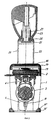
Фиг. 2 - вертикальный разрез собранного штемпельного устройства в плоскости II-II согласно фиг. 1,
Фиг. 3 - вертикальный разрез собранного штемпельного устройства в плоскости III-III согласно фиг. 1.The invention is illustrated in detail with examples using the drawings, which show:
FIG. 1 is a view of a stamping device according to the invention,
FIG. 2 is a vertical section through an assembled stamping device in plane II-II of FIG. 1,
FIG. 3 is a vertical section through an assembled stamping device in plane III-III of FIG. 1.
Показанное на чертежах штемпельное устройство имеет в основном параллелепипедный внешний корпус 1 из пластмассы для размещения штемпельной подушки 2 для штемпельной вставки 3. Предусмотренная в показанном примере штемпельная вставка 3 для печатания даты устанавливается вместе с поворотным механизмом 4 с изогнутым направляющим шлицем 5 в вставляемой во внешний корпус раскрытой вверх U-образной крепежной раме 6 из металла с помощью цапф 4', которые входят в отверстия 6'' металлической рамы. Поперечная ось проходит через образованные в плечах 6' крепежной рамы 6 прямолинейные шлицы 8 и одновременно через направляющие шлицы 5 поворотного механизма 4 штемпельной вставки 3. Поперечная ось 7 вставляется со стороны перед одеванием внешнего корпуса 1 на крепежную раму 6. The stamp device shown in the drawings has a substantially parallelepiped outer case 1 made of plastic for accommodating the
Поперечная часть металлической рамы 6 образует далее прижимную часть 9 рамы, которая соединяет плечи 6' и образует отверстие 10 для прохождения штемпельной вставки 3. Поперечные перемычки 9' прижимной части 9 рамы имеют отверстия 11 для приема цапф 12, которые выступают из пластмассовых планок 13, изготовленных из эластичного, резиноподобного материала, например термопластичного эластомера, которые накладываются на поперечные перемычки 9', и их назначение будет еще подробно описано ниже с помощью фиг. 2. The transverse part of the
Окружающий внутреннюю металлическую раму 6 внешний корпус 1 из пластмассы имеет на своих боковых частях 14 выгнутые наружу карманы 15 с опорами 15' для пружин для размещения пружин сжатия 16. Боковые части 14 соединены друг с другом верхними и нижними поперечными соединениями 17', 17''. Верхнее поперечное соединение 17' боковых частей 14 внешнего корпуса 1 закрывает сверху штемпельную подушку 2 и образует углубленное пространство 18 для размещения (не изображенного) листа с оттиском печати, соответственно, служит поверхностью для оттиска образца печати с возможностью закрывания от повреждения и загрязнения с помощью прозрачной крышки 19. The outer plastic housing 1 surrounding the
Управляющий элемент 20 штемпельного устройства имеет внутреннюю U-образную скобу 21 из металла и охватывающую ее, выполненную из пластмассы внешнюю раму 22, на которой установлена также выполненная из пластмассы рукоятка 23. Плечи 21' управляющей скобы 21 входят в карманы 15 боковых частей 14 корпуса, где они фиксируются концами поперечной оси 7, которые входят в плечи 6', которые в свою очередь при сборке входят в соединенные с карманами 15 приемные шлицы 24 корпуса 1. Плечи 22' внешней рамы 22 также вводятся в карманы 15 корпуса 1. Кроме того, в карманы 15 вставляются извне фиксирующие кнопки 15'' для зацепления в углубления 22'' внешнего корпуса 22. The
Соединение управляющей скобы 21 и пластмассовой рамы 22 происходит с помощью пружинно деформируемой цапфы 25, которая проходит через отверстие 26 в управляющей скобе 21 и входит в приемную втулку 27 головки 23. Управляющая скоба 21 отверстиями 28 в своих плечах заскакивает на выпуклые шишечки 29 штемпельной вставки 3. The
На фиг. 2 и 3 показано штемпельное устройство в положении, в котором происходит забор краски со сменной штемпельной подушки 2. Как особенно отчетливо показано на фиг. 2, рукоятка 23 состоит из двух соединенных друг с другом частей и соединена с помощью цапфы 25 с управляющей скобой 21. Далее на фиг. 2 показано углубление 18 для размещения образца оттиска, а также выполнение пластмассовых планок 13, внутренняя сторона которых выгнута так, что она образует направляющую для штемпельной вставки 3. Проходящие через отверстия 11 цапфы 12, 13 образуют их нижней стороной препятствие для смещения штемпельного устройства, что особенно выгодно для центрирования его при оттиске. In FIG. 2 and 3, the stamping device is shown in the position in which paint is taken from the
Штемпельная вставка показана на фиг. 3 в положении штемпельного устройства, когда управляющая скоба 21 нажата вниз против действия пружин сжатия 16 при повороте штемпельной вставки 3 с помощью направляющего изгиба 5 и оси 7 в положение оттиска. При этом штемпельная вставка 3 проходит через отверстие 10 прижимной части 9 рамы и входит в плотный контакт с подлежащим печати носителем. The stamp insert is shown in FIG. 3 in the position of the stamping device, when the
В устройстве согласно изобретению крепежная рама для штемпельной вставки и управляющая скоба изготовлены, предпочтительно, из металла, например, цинка, а внешний корпус, соответственно, внешняя рама выполнены из пластмассы, однако все устройство может быть выполнено из пластмассы. In the device according to the invention, the mounting frame for the stamping insert and the control bracket are preferably made of metal, for example zinc, and the outer casing, respectively, the outer frame is made of plastic, however, the whole device can be made of plastic.
Claims (6)
Applications Claiming Priority (3)
| Application Number | Priority Date | Filing Date | Title |
|---|---|---|---|
| ATA2229/94 | 1994-12-01 | ||
| AT0222994A AT404695B (en) | 1994-12-01 | 1994-12-01 | STAMP DEVICE |
| PCT/AT1995/000235 WO1996016816A1 (en) | 1994-12-01 | 1995-11-29 | Stamping device |
Publications (2)
| Publication Number | Publication Date |
|---|---|
| RU97111040A RU97111040A (en) | 1999-06-10 |
| RU2139197C1 true RU2139197C1 (en) | 1999-10-10 |
Family
ID=3530432
Family Applications (1)
| Application Number | Title | Priority Date | Filing Date |
|---|---|---|---|
| RU97111040/12A RU2139197C1 (en) | 1994-12-01 | 1995-11-29 | Stamping device |
Country Status (18)
| Country | Link |
|---|---|
| US (1) | US5850787A (en) |
| EP (1) | EP0804344B1 (en) |
| JP (1) | JP3166860B2 (en) |
| CN (1) | CN1080649C (en) |
| AR (1) | AR000221A1 (en) |
| AT (2) | AT404695B (en) |
| AU (1) | AU689668B2 (en) |
| DE (3) | DE59503468D1 (en) |
| DK (1) | DK0804344T3 (en) |
| ES (1) | ES2121431T3 (en) |
| HK (1) | HK1004128A1 (en) |
| HR (1) | HRP950582B1 (en) |
| IL (1) | IL116034A (en) |
| PE (1) | PE14897A1 (en) |
| RU (1) | RU2139197C1 (en) |
| TR (1) | TR199501505A2 (en) |
| WO (1) | WO1996016816A1 (en) |
| ZA (1) | ZA9510059B (en) |
Cited By (1)
| Publication number | Priority date | Publication date | Assignee | Title |
|---|---|---|---|---|
| RU2783571C2 (en) * | 2015-06-10 | 2022-11-14 | Тродат Гмбх | Stamp |
Families Citing this family (28)
| Publication number | Priority date | Publication date | Assignee | Title |
|---|---|---|---|---|
| US6948257B1 (en) * | 1998-02-27 | 2005-09-27 | Barr Jr William A | Marking device with self-hinged contact plate and marking members |
| US7334342B1 (en) | 1998-02-27 | 2008-02-26 | William Ack Barr | Marking device having marking members |
| AT2996U1 (en) * | 1998-10-14 | 1999-08-25 | Colop Stempelerzeugung Skopek | AXLE LOCKING FOR THE TURNING AXLE OF A HAND STAMP AND HAND STAMP |
| AT409742B (en) * | 2001-01-25 | 2002-10-25 | Trodat Gmbh | COLOR PILLOW FOR A SELF-COLORING STAMP |
| JP2002273996A (en) * | 2001-03-21 | 2002-09-25 | Yamahachi Chemical Co Ltd | Liquid permeable stamp with a plurality of stamping faces |
| US20030131818A1 (en) * | 2002-01-16 | 2003-07-17 | Kyle Gregoire | Intake manifold paddle system |
| AT411976B (en) * | 2002-05-27 | 2004-08-26 | Trodat Gmbh | STAMP AND RECEIVING DEVICE FOR A STAMP PILLOW |
| AT414342B (en) * | 2002-05-27 | 2011-09-15 | Trodat Gmbh | STAMP AND RECORDING DEVICE FOR A STAMPING CUSHION |
| US6945172B1 (en) * | 2004-06-10 | 2005-09-20 | Shiny Shih | Housing assembly for a self-inking stamp |
| AT501318B1 (en) * | 2005-01-25 | 2006-11-15 | Colop Stempelerzeugung Skopek | self-inking stamp |
| US8387528B2 (en) * | 2009-01-15 | 2013-03-05 | Crayola Llc | Self-sealing stamping device |
| AT508167B1 (en) | 2009-04-17 | 2011-07-15 | Colop Stempelerzeugung Skopek | Self-inking hand TEMPLE |
| AT508168B1 (en) * | 2009-04-17 | 2011-08-15 | Colop Stempelerzeugung Skopek | Self-inking hand TEMPLE |
| JP5162801B2 (en) * | 2009-06-24 | 2013-03-13 | シヤチハタ株式会社 | Reversing stamp |
| JP5294157B2 (en) * | 2009-06-24 | 2013-09-18 | シヤチハタ株式会社 | Reversing stamp |
| AT511453B1 (en) * | 2011-05-24 | 2012-12-15 | Trodat Gmbh | STAMP AND ASSOCIATED STAMP PILLOW |
| CN102490502B (en) * | 2011-12-08 | 2014-04-16 | 北京科富兴科技有限公司 | Stamp with anti-counterfeiting code and anti-counterfeiting method |
| AT514245A1 (en) | 2013-04-22 | 2014-11-15 | Colop Stempelerzeugung Skopek | Ink pad holder and apparatus and method for producing such |
| JP5984778B2 (en) * | 2013-10-25 | 2016-09-06 | サンビー株式会社 | Stamp stand |
| PL3388246T3 (en) | 2014-01-10 | 2019-11-29 | Trotec Laser Gmbh | Machining system for multiple different workpieces |
| AT517318A1 (en) | 2015-06-10 | 2016-12-15 | Trodat Gmbh | Stamp and impression unit |
| AT517322A1 (en) * | 2015-06-10 | 2016-12-15 | Trodat Gmbh | Stamp and impression unit, in particular as a spare part for a stamp |
| AT517328A1 (en) | 2015-06-10 | 2016-12-15 | Trodat Gmbh | Stamp, a stamp pad and a cap |
| AT517321A1 (en) | 2015-06-10 | 2016-12-15 | Trodat Gmbh | stamp |
| USD823378S1 (en) | 2015-06-10 | 2018-07-17 | Trodat Gmbh | Hand stamp |
| USD803307S1 (en) | 2015-12-10 | 2017-11-21 | Trodat Gmbh | Hand stamp |
| AT518735A1 (en) | 2016-06-09 | 2017-12-15 | Trodat Gmbh | Drive unit, belt unit, bridge, driver and punch for this purpose |
| AT519177B1 (en) | 2016-10-06 | 2019-04-15 | Trotec Laser Gmbh | Method for engraving, marking and / or inscribing a workpiece with |
Family Cites Families (9)
| Publication number | Priority date | Publication date | Assignee | Title |
|---|---|---|---|---|
| US1834629A (en) * | 1930-03-17 | 1931-12-01 | John J Gleason | Self inking stamp holder |
| US2075169A (en) * | 1935-11-29 | 1937-03-30 | Eric F Brown | Apparatus for imprinting tax indicia on items |
| DE1113221B (en) * | 1959-06-23 | 1961-08-31 | Fritz Schoettgen | Self-inking stamp |
| DE1276662B (en) * | 1960-05-04 | 1968-09-05 | Hans Schnaeckel G M B H | Self-inking |
| US3099955A (en) * | 1961-05-16 | 1963-08-06 | Jack W Robbins | Type band setting means in hand stamps |
| DE2020162A1 (en) * | 1970-04-24 | 1971-11-11 | Hans Schnaeckel Gmbh | Self-inking hand stamp |
| US4432281A (en) * | 1982-03-10 | 1984-02-21 | M & R Seal Press Co., Inc. | Self-inking stamping device |
| US4852489A (en) * | 1987-11-18 | 1989-08-01 | M&R Marking Systems, Inc. | Self-inking stamping device |
| AT388332B (en) * | 1988-01-25 | 1989-06-12 | Just Gmbh Walter | SELF-COLORING STAMP WITH ROLL-ON COLORING |
-
1994
- 1994-12-01 AT AT0222994A patent/AT404695B/en not_active IP Right Cessation
-
1995
- 1995-11-16 IL IL11603495A patent/IL116034A/en not_active IP Right Cessation
- 1995-11-27 ZA ZA9510059A patent/ZA9510059B/en unknown
- 1995-11-28 AR AR33441995A patent/AR000221A1/en unknown
- 1995-11-28 TR TR95/01505A patent/TR199501505A2/en unknown
- 1995-11-29 DK DK95938299T patent/DK0804344T3/en active
- 1995-11-29 CN CN95196512A patent/CN1080649C/en not_active Expired - Fee Related
- 1995-11-29 RU RU97111040/12A patent/RU2139197C1/en not_active IP Right Cessation
- 1995-11-29 EP EP95938299A patent/EP0804344B1/en not_active Expired - Lifetime
- 1995-11-29 DE DE59503468T patent/DE59503468D1/en not_active Expired - Lifetime
- 1995-11-29 AU AU39738/95A patent/AU689668B2/en not_active Ceased
- 1995-11-29 AT AT95938299T patent/ATE170464T1/en active
- 1995-11-29 DE DE29521420U patent/DE29521420U1/en not_active Expired - Lifetime
- 1995-11-29 US US08/836,796 patent/US5850787A/en not_active Expired - Lifetime
- 1995-11-29 WO PCT/AT1995/000235 patent/WO1996016816A1/en active IP Right Grant
- 1995-11-29 ES ES95938299T patent/ES2121431T3/en not_active Expired - Lifetime
- 1995-11-29 DE DE29521411U patent/DE29521411U1/en not_active Expired - Lifetime
- 1995-11-29 JP JP51790296A patent/JP3166860B2/en not_active Expired - Fee Related
- 1995-12-01 PE PE1995286275A patent/PE14897A1/en not_active Application Discontinuation
- 1995-12-01 HR HRA2229/94A patent/HRP950582B1/en not_active IP Right Cessation
-
1998
- 1998-04-28 HK HK98103575A patent/HK1004128A1/en not_active IP Right Cessation
Cited By (1)
| Publication number | Priority date | Publication date | Assignee | Title |
|---|---|---|---|---|
| RU2783571C2 (en) * | 2015-06-10 | 2022-11-14 | Тродат Гмбх | Stamp |
Also Published As
| Publication number | Publication date |
|---|---|
| CN1167463A (en) | 1997-12-10 |
| IL116034A0 (en) | 1996-01-31 |
| DE29521411U1 (en) | 1997-03-20 |
| AU3973895A (en) | 1996-06-19 |
| PE14897A1 (en) | 1997-05-19 |
| ATE170464T1 (en) | 1998-09-15 |
| HK1004128A1 (en) | 1998-11-20 |
| EP0804344A1 (en) | 1997-11-05 |
| US5850787A (en) | 1998-12-22 |
| ATA222994A (en) | 1998-06-15 |
| DK0804344T3 (en) | 1999-02-08 |
| AT404695B (en) | 1999-01-25 |
| ES2121431T3 (en) | 1998-11-16 |
| DE59503468D1 (en) | 1998-10-08 |
| ZA9510059B (en) | 1996-06-06 |
| AU689668B2 (en) | 1998-04-02 |
| HRP950582A2 (en) | 1997-06-30 |
| TR199501505A2 (en) | 1996-07-21 |
| IL116034A (en) | 2000-01-31 |
| JP3166860B2 (en) | 2001-05-14 |
| EP0804344B1 (en) | 1998-09-02 |
| WO1996016816A1 (en) | 1996-06-06 |
| JPH10509668A (en) | 1998-09-22 |
| AR000221A1 (en) | 1997-05-28 |
| HRP950582B1 (en) | 1999-12-31 |
| CN1080649C (en) | 2002-03-13 |
| DE29521420U1 (en) | 1997-03-20 |
Similar Documents
| Publication | Publication Date | Title |
|---|---|---|
| RU2139197C1 (en) | Stamping device | |
| RU97111040A (en) | STAMP DEVICE | |
| US4970954A (en) | Self inking hand stamp | |
| US4428116A (en) | Support for releasably retaining a blade cartridge | |
| ES2282243T3 (en) | AUTOMATIC TINTING SEAL. | |
| JP5294157B2 (en) | Reversing stamp | |
| JP2008043783A (en) | Shaving system and method | |
| CA2203217A1 (en) | Eyeglasses frame with spring hinges | |
| US5855170A (en) | Ink-replenishable signet | |
| KR960021549A (en) | Stamp body, stamp unit and punching device | |
| RU2002132560A (en) | SELF-DYING STAMP | |
| RU2469870C2 (en) | Pocket stamp | |
| CN210129096U (en) | Camera automatic focusing machine anchor clamps | |
| JP4316828B2 (en) | Seal case | |
| JPS5832648B2 (en) | Kiroku Penhongtai | |
| JP4248008B2 (en) | stamp | |
| CN214731045U (en) | Storage box | |
| JP2579086Y2 (en) | Seal | |
| KR100191240B1 (en) | Conclusion structure of a wiper blade | |
| JP2823184B2 (en) | Ink ribbon cassette | |
| JP2585632Y2 (en) | Inverted seal | |
| KR870003463Y1 (en) | Ring collar assembling device | |
| JP2599062Y2 (en) | Inverted seal | |
| JP2585631Y2 (en) | Inverted seal | |
| KR960004269Y1 (en) | Buckle |
Legal Events
| Date | Code | Title | Description |
|---|---|---|---|
| PC4A | Invention patent assignment |
Effective date: 20050818 |
|
| MM4A | The patent is invalid due to non-payment of fees |
Effective date: 20141130 |