RU2136358C1 - Method and device for temperature monitoring (modifications) and method for catalytic dehydrogeneration of hydrocarbons - Google Patents
Method and device for temperature monitoring (modifications) and method for catalytic dehydrogeneration of hydrocarbons Download PDFInfo
- Publication number
- RU2136358C1 RU2136358C1 RU96101993A RU96101993A RU2136358C1 RU 2136358 C1 RU2136358 C1 RU 2136358C1 RU 96101993 A RU96101993 A RU 96101993A RU 96101993 A RU96101993 A RU 96101993A RU 2136358 C1 RU2136358 C1 RU 2136358C1
- Authority
- RU
- Russia
- Prior art keywords
- reaction
- partitions
- reagent
- flow
- channels
- Prior art date
Links
Images


Classifications
-
- B—PERFORMING OPERATIONS; TRANSPORTING
- B01—PHYSICAL OR CHEMICAL PROCESSES OR APPARATUS IN GENERAL
- B01J—CHEMICAL OR PHYSICAL PROCESSES, e.g. CATALYSIS OR COLLOID CHEMISTRY; THEIR RELEVANT APPARATUS
- B01J8/00—Chemical or physical processes in general, conducted in the presence of fluids and solid particles; Apparatus for such processes
- B01J8/02—Chemical or physical processes in general, conducted in the presence of fluids and solid particles; Apparatus for such processes with stationary particles, e.g. in fixed beds
-
- F—MECHANICAL ENGINEERING; LIGHTING; HEATING; WEAPONS; BLASTING
- F28—HEAT EXCHANGE IN GENERAL
- F28F—DETAILS OF HEAT-EXCHANGE AND HEAT-TRANSFER APPARATUS, OF GENERAL APPLICATION
- F28F3/00—Plate-like or laminated elements; Assemblies of plate-like or laminated elements
- F28F3/02—Elements or assemblies thereof with means for increasing heat-transfer area, e.g. with fins, with recesses, with corrugations
- F28F3/04—Elements or assemblies thereof with means for increasing heat-transfer area, e.g. with fins, with recesses, with corrugations the means being integral with the element
- F28F3/042—Elements or assemblies thereof with means for increasing heat-transfer area, e.g. with fins, with recesses, with corrugations the means being integral with the element in the form of local deformations of the element
- F28F3/046—Elements or assemblies thereof with means for increasing heat-transfer area, e.g. with fins, with recesses, with corrugations the means being integral with the element in the form of local deformations of the element the deformations being linear, e.g. corrugations
-
- B—PERFORMING OPERATIONS; TRANSPORTING
- B01—PHYSICAL OR CHEMICAL PROCESSES OR APPARATUS IN GENERAL
- B01J—CHEMICAL OR PHYSICAL PROCESSES, e.g. CATALYSIS OR COLLOID CHEMISTRY; THEIR RELEVANT APPARATUS
- B01J19/00—Chemical, physical or physico-chemical processes in general; Their relevant apparatus
- B01J19/24—Stationary reactors without moving elements inside
- B01J19/248—Reactors comprising multiple separated flow channels
- B01J19/249—Plate-type reactors
-
- B—PERFORMING OPERATIONS; TRANSPORTING
- B01—PHYSICAL OR CHEMICAL PROCESSES OR APPARATUS IN GENERAL
- B01J—CHEMICAL OR PHYSICAL PROCESSES, e.g. CATALYSIS OR COLLOID CHEMISTRY; THEIR RELEVANT APPARATUS
- B01J19/00—Chemical, physical or physico-chemical processes in general; Their relevant apparatus
- B01J19/32—Packing elements in the form of grids or built-up elements for forming a unit or module inside the apparatus for mass or heat transfer
-
- B—PERFORMING OPERATIONS; TRANSPORTING
- B01—PHYSICAL OR CHEMICAL PROCESSES OR APPARATUS IN GENERAL
- B01J—CHEMICAL OR PHYSICAL PROCESSES, e.g. CATALYSIS OR COLLOID CHEMISTRY; THEIR RELEVANT APPARATUS
- B01J8/00—Chemical or physical processes in general, conducted in the presence of fluids and solid particles; Apparatus for such processes
- B01J8/02—Chemical or physical processes in general, conducted in the presence of fluids and solid particles; Apparatus for such processes with stationary particles, e.g. in fixed beds
- B01J8/0207—Chemical or physical processes in general, conducted in the presence of fluids and solid particles; Apparatus for such processes with stationary particles, e.g. in fixed beds the fluid flow within the bed being predominantly horizontal
-
- B—PERFORMING OPERATIONS; TRANSPORTING
- B01—PHYSICAL OR CHEMICAL PROCESSES OR APPARATUS IN GENERAL
- B01J—CHEMICAL OR PHYSICAL PROCESSES, e.g. CATALYSIS OR COLLOID CHEMISTRY; THEIR RELEVANT APPARATUS
- B01J8/00—Chemical or physical processes in general, conducted in the presence of fluids and solid particles; Apparatus for such processes
- B01J8/02—Chemical or physical processes in general, conducted in the presence of fluids and solid particles; Apparatus for such processes with stationary particles, e.g. in fixed beds
- B01J8/0285—Heating or cooling the reactor
-
- B—PERFORMING OPERATIONS; TRANSPORTING
- B01—PHYSICAL OR CHEMICAL PROCESSES OR APPARATUS IN GENERAL
- B01J—CHEMICAL OR PHYSICAL PROCESSES, e.g. CATALYSIS OR COLLOID CHEMISTRY; THEIR RELEVANT APPARATUS
- B01J8/00—Chemical or physical processes in general, conducted in the presence of fluids and solid particles; Apparatus for such processes
- B01J8/02—Chemical or physical processes in general, conducted in the presence of fluids and solid particles; Apparatus for such processes with stationary particles, e.g. in fixed beds
- B01J8/04—Chemical or physical processes in general, conducted in the presence of fluids and solid particles; Apparatus for such processes with stationary particles, e.g. in fixed beds the fluid passing successively through two or more beds
- B01J8/0403—Chemical or physical processes in general, conducted in the presence of fluids and solid particles; Apparatus for such processes with stationary particles, e.g. in fixed beds the fluid passing successively through two or more beds the fluid flow within the beds being predominantly horizontal
-
- B—PERFORMING OPERATIONS; TRANSPORTING
- B01—PHYSICAL OR CHEMICAL PROCESSES OR APPARATUS IN GENERAL
- B01J—CHEMICAL OR PHYSICAL PROCESSES, e.g. CATALYSIS OR COLLOID CHEMISTRY; THEIR RELEVANT APPARATUS
- B01J8/00—Chemical or physical processes in general, conducted in the presence of fluids and solid particles; Apparatus for such processes
- B01J8/08—Chemical or physical processes in general, conducted in the presence of fluids and solid particles; Apparatus for such processes with moving particles
- B01J8/087—Heating or cooling the reactor
-
- B—PERFORMING OPERATIONS; TRANSPORTING
- B01—PHYSICAL OR CHEMICAL PROCESSES OR APPARATUS IN GENERAL
- B01J—CHEMICAL OR PHYSICAL PROCESSES, e.g. CATALYSIS OR COLLOID CHEMISTRY; THEIR RELEVANT APPARATUS
- B01J8/00—Chemical or physical processes in general, conducted in the presence of fluids and solid particles; Apparatus for such processes
- B01J8/08—Chemical or physical processes in general, conducted in the presence of fluids and solid particles; Apparatus for such processes with moving particles
- B01J8/12—Chemical or physical processes in general, conducted in the presence of fluids and solid particles; Apparatus for such processes with moving particles moved by gravity in a downward flow
- B01J8/125—Chemical or physical processes in general, conducted in the presence of fluids and solid particles; Apparatus for such processes with moving particles moved by gravity in a downward flow with multiple sections one above the other separated by distribution aids, e.g. reaction and regeneration sections
-
- F—MECHANICAL ENGINEERING; LIGHTING; HEATING; WEAPONS; BLASTING
- F28—HEAT EXCHANGE IN GENERAL
- F28D—HEAT-EXCHANGE APPARATUS, NOT PROVIDED FOR IN ANOTHER SUBCLASS, IN WHICH THE HEAT-EXCHANGE MEDIA DO NOT COME INTO DIRECT CONTACT
- F28D9/00—Heat-exchange apparatus having stationary plate-like or laminated conduit assemblies for both heat-exchange media, the media being in contact with different sides of a conduit wall
- F28D9/0006—Heat-exchange apparatus having stationary plate-like or laminated conduit assemblies for both heat-exchange media, the media being in contact with different sides of a conduit wall the plate-like or laminated conduits being enclosed within a pressure vessel
-
- F—MECHANICAL ENGINEERING; LIGHTING; HEATING; WEAPONS; BLASTING
- F28—HEAT EXCHANGE IN GENERAL
- F28F—DETAILS OF HEAT-EXCHANGE AND HEAT-TRANSFER APPARATUS, OF GENERAL APPLICATION
- F28F13/00—Arrangements for modifying heat-transfer, e.g. increasing, decreasing
- F28F13/14—Arrangements for modifying heat-transfer, e.g. increasing, decreasing by endowing the walls of conduits with zones of different degrees of conduction of heat
-
- F—MECHANICAL ENGINEERING; LIGHTING; HEATING; WEAPONS; BLASTING
- F28—HEAT EXCHANGE IN GENERAL
- F28F—DETAILS OF HEAT-EXCHANGE AND HEAT-TRANSFER APPARATUS, OF GENERAL APPLICATION
- F28F3/00—Plate-like or laminated elements; Assemblies of plate-like or laminated elements
- F28F3/02—Elements or assemblies thereof with means for increasing heat-transfer area, e.g. with fins, with recesses, with corrugations
- F28F3/025—Elements or assemblies thereof with means for increasing heat-transfer area, e.g. with fins, with recesses, with corrugations the means being corrugated, plate-like elements
-
- B—PERFORMING OPERATIONS; TRANSPORTING
- B01—PHYSICAL OR CHEMICAL PROCESSES OR APPARATUS IN GENERAL
- B01J—CHEMICAL OR PHYSICAL PROCESSES, e.g. CATALYSIS OR COLLOID CHEMISTRY; THEIR RELEVANT APPARATUS
- B01J2208/00—Processes carried out in the presence of solid particles; Reactors therefor
- B01J2208/00008—Controlling the process
- B01J2208/00017—Controlling the temperature
- B01J2208/00106—Controlling the temperature by indirect heat exchange
- B01J2208/00115—Controlling the temperature by indirect heat exchange with heat exchange elements inside the bed of solid particles
- B01J2208/0015—Plates; Cylinders
-
- B—PERFORMING OPERATIONS; TRANSPORTING
- B01—PHYSICAL OR CHEMICAL PROCESSES OR APPARATUS IN GENERAL
- B01J—CHEMICAL OR PHYSICAL PROCESSES, e.g. CATALYSIS OR COLLOID CHEMISTRY; THEIR RELEVANT APPARATUS
- B01J2208/00—Processes carried out in the presence of solid particles; Reactors therefor
- B01J2208/02—Processes carried out in the presence of solid particles; Reactors therefor with stationary particles
- B01J2208/021—Processes carried out in the presence of solid particles; Reactors therefor with stationary particles comprising a plurality of beds with flow of reactants in parallel
- B01J2208/022—Plate-type reactors filled with granular catalyst
-
- B—PERFORMING OPERATIONS; TRANSPORTING
- B01—PHYSICAL OR CHEMICAL PROCESSES OR APPARATUS IN GENERAL
- B01J—CHEMICAL OR PHYSICAL PROCESSES, e.g. CATALYSIS OR COLLOID CHEMISTRY; THEIR RELEVANT APPARATUS
- B01J2219/00—Chemical, physical or physico-chemical processes in general; Their relevant apparatus
- B01J2219/24—Stationary reactors without moving elements inside
- B01J2219/2401—Reactors comprising multiple separate flow channels
- B01J2219/245—Plate-type reactors
- B01J2219/2451—Geometry of the reactor
- B01J2219/2453—Plates arranged in parallel
-
- B—PERFORMING OPERATIONS; TRANSPORTING
- B01—PHYSICAL OR CHEMICAL PROCESSES OR APPARATUS IN GENERAL
- B01J—CHEMICAL OR PHYSICAL PROCESSES, e.g. CATALYSIS OR COLLOID CHEMISTRY; THEIR RELEVANT APPARATUS
- B01J2219/00—Chemical, physical or physico-chemical processes in general; Their relevant apparatus
- B01J2219/24—Stationary reactors without moving elements inside
- B01J2219/2401—Reactors comprising multiple separate flow channels
- B01J2219/245—Plate-type reactors
- B01J2219/2451—Geometry of the reactor
- B01J2219/2456—Geometry of the plates
- B01J2219/2459—Corrugated plates
-
- B—PERFORMING OPERATIONS; TRANSPORTING
- B01—PHYSICAL OR CHEMICAL PROCESSES OR APPARATUS IN GENERAL
- B01J—CHEMICAL OR PHYSICAL PROCESSES, e.g. CATALYSIS OR COLLOID CHEMISTRY; THEIR RELEVANT APPARATUS
- B01J2219/00—Chemical, physical or physico-chemical processes in general; Their relevant apparatus
- B01J2219/24—Stationary reactors without moving elements inside
- B01J2219/2401—Reactors comprising multiple separate flow channels
- B01J2219/245—Plate-type reactors
- B01J2219/2461—Heat exchange aspects
- B01J2219/2462—Heat exchange aspects the reactants being in indirect heat exchange with a non reacting heat exchange medium
- B01J2219/2464—Independent temperature control in various sections of the reactor
-
- B—PERFORMING OPERATIONS; TRANSPORTING
- B01—PHYSICAL OR CHEMICAL PROCESSES OR APPARATUS IN GENERAL
- B01J—CHEMICAL OR PHYSICAL PROCESSES, e.g. CATALYSIS OR COLLOID CHEMISTRY; THEIR RELEVANT APPARATUS
- B01J2219/00—Chemical, physical or physico-chemical processes in general; Their relevant apparatus
- B01J2219/24—Stationary reactors without moving elements inside
- B01J2219/2401—Reactors comprising multiple separate flow channels
- B01J2219/245—Plate-type reactors
- B01J2219/2469—Feeding means
- B01J2219/247—Feeding means for the reactants
-
- B—PERFORMING OPERATIONS; TRANSPORTING
- B01—PHYSICAL OR CHEMICAL PROCESSES OR APPARATUS IN GENERAL
- B01J—CHEMICAL OR PHYSICAL PROCESSES, e.g. CATALYSIS OR COLLOID CHEMISTRY; THEIR RELEVANT APPARATUS
- B01J2219/00—Chemical, physical or physico-chemical processes in general; Their relevant apparatus
- B01J2219/24—Stationary reactors without moving elements inside
- B01J2219/2401—Reactors comprising multiple separate flow channels
- B01J2219/245—Plate-type reactors
- B01J2219/2469—Feeding means
- B01J2219/2471—Feeding means for the catalyst
-
- B—PERFORMING OPERATIONS; TRANSPORTING
- B01—PHYSICAL OR CHEMICAL PROCESSES OR APPARATUS IN GENERAL
- B01J—CHEMICAL OR PHYSICAL PROCESSES, e.g. CATALYSIS OR COLLOID CHEMISTRY; THEIR RELEVANT APPARATUS
- B01J2219/00—Chemical, physical or physico-chemical processes in general; Their relevant apparatus
- B01J2219/24—Stationary reactors without moving elements inside
- B01J2219/2401—Reactors comprising multiple separate flow channels
- B01J2219/245—Plate-type reactors
- B01J2219/2474—Mixing means, e.g. fins or baffles attached to the plates
-
- B—PERFORMING OPERATIONS; TRANSPORTING
- B01—PHYSICAL OR CHEMICAL PROCESSES OR APPARATUS IN GENERAL
- B01J—CHEMICAL OR PHYSICAL PROCESSES, e.g. CATALYSIS OR COLLOID CHEMISTRY; THEIR RELEVANT APPARATUS
- B01J2219/00—Chemical, physical or physico-chemical processes in general; Their relevant apparatus
- B01J2219/24—Stationary reactors without moving elements inside
- B01J2219/2401—Reactors comprising multiple separate flow channels
- B01J2219/245—Plate-type reactors
- B01J2219/2476—Construction materials
- B01J2219/2477—Construction materials of the catalysts
- B01J2219/2481—Catalysts in granular from between plates
-
- B—PERFORMING OPERATIONS; TRANSPORTING
- B01—PHYSICAL OR CHEMICAL PROCESSES OR APPARATUS IN GENERAL
- B01J—CHEMICAL OR PHYSICAL PROCESSES, e.g. CATALYSIS OR COLLOID CHEMISTRY; THEIR RELEVANT APPARATUS
- B01J2219/00—Chemical, physical or physico-chemical processes in general; Their relevant apparatus
- B01J2219/24—Stationary reactors without moving elements inside
- B01J2219/2401—Reactors comprising multiple separate flow channels
- B01J2219/245—Plate-type reactors
- B01J2219/2491—Other constructional details
- B01J2219/2498—Additional structures inserted in the channels, e.g. plates, catalyst holding meshes
-
- B—PERFORMING OPERATIONS; TRANSPORTING
- B01—PHYSICAL OR CHEMICAL PROCESSES OR APPARATUS IN GENERAL
- B01J—CHEMICAL OR PHYSICAL PROCESSES, e.g. CATALYSIS OR COLLOID CHEMISTRY; THEIR RELEVANT APPARATUS
- B01J2219/00—Chemical, physical or physico-chemical processes in general; Their relevant apparatus
- B01J2219/32—Details relating to packing elements in the form of grids or built-up elements for forming a unit of module inside the apparatus for mass or heat transfer
- B01J2219/322—Basic shape of the elements
- B01J2219/32203—Sheets
- B01J2219/3221—Corrugated sheets
-
- B—PERFORMING OPERATIONS; TRANSPORTING
- B01—PHYSICAL OR CHEMICAL PROCESSES OR APPARATUS IN GENERAL
- B01J—CHEMICAL OR PHYSICAL PROCESSES, e.g. CATALYSIS OR COLLOID CHEMISTRY; THEIR RELEVANT APPARATUS
- B01J2219/00—Chemical, physical or physico-chemical processes in general; Their relevant apparatus
- B01J2219/32—Details relating to packing elements in the form of grids or built-up elements for forming a unit of module inside the apparatus for mass or heat transfer
- B01J2219/322—Basic shape of the elements
- B01J2219/32203—Sheets
- B01J2219/32224—Sheets characterised by the orientation of the sheet
- B01J2219/32227—Vertical orientation
-
- B—PERFORMING OPERATIONS; TRANSPORTING
- B01—PHYSICAL OR CHEMICAL PROCESSES OR APPARATUS IN GENERAL
- B01J—CHEMICAL OR PHYSICAL PROCESSES, e.g. CATALYSIS OR COLLOID CHEMISTRY; THEIR RELEVANT APPARATUS
- B01J2219/00—Chemical, physical or physico-chemical processes in general; Their relevant apparatus
- B01J2219/32—Details relating to packing elements in the form of grids or built-up elements for forming a unit of module inside the apparatus for mass or heat transfer
- B01J2219/324—Composition or microstructure of the elements
- B01J2219/32466—Composition or microstructure of the elements comprising catalytically active material
- B01J2219/32475—Composition or microstructure of the elements comprising catalytically active material involving heat exchange
-
- B—PERFORMING OPERATIONS; TRANSPORTING
- B01—PHYSICAL OR CHEMICAL PROCESSES OR APPARATUS IN GENERAL
- B01J—CHEMICAL OR PHYSICAL PROCESSES, e.g. CATALYSIS OR COLLOID CHEMISTRY; THEIR RELEVANT APPARATUS
- B01J2219/00—Chemical, physical or physico-chemical processes in general; Their relevant apparatus
- B01J2219/32—Details relating to packing elements in the form of grids or built-up elements for forming a unit of module inside the apparatus for mass or heat transfer
- B01J2219/326—Mathematical modelling
-
- F—MECHANICAL ENGINEERING; LIGHTING; HEATING; WEAPONS; BLASTING
- F28—HEAT EXCHANGE IN GENERAL
- F28F—DETAILS OF HEAT-EXCHANGE AND HEAT-TRANSFER APPARATUS, OF GENERAL APPLICATION
- F28F2215/00—Fins
- F28F2215/04—Assemblies of fins having different features, e.g. with different fin densities
-
- Y—GENERAL TAGGING OF NEW TECHNOLOGICAL DEVELOPMENTS; GENERAL TAGGING OF CROSS-SECTIONAL TECHNOLOGIES SPANNING OVER SEVERAL SECTIONS OF THE IPC; TECHNICAL SUBJECTS COVERED BY FORMER USPC CROSS-REFERENCE ART COLLECTIONS [XRACs] AND DIGESTS
- Y02—TECHNOLOGIES OR APPLICATIONS FOR MITIGATION OR ADAPTATION AGAINST CLIMATE CHANGE
- Y02P—CLIMATE CHANGE MITIGATION TECHNOLOGIES IN THE PRODUCTION OR PROCESSING OF GOODS
- Y02P20/00—Technologies relating to chemical industry
- Y02P20/50—Improvements relating to the production of bulk chemicals
- Y02P20/582—Recycling of unreacted starting or intermediate materials
Abstract
Description
Изобретение относится к химическим реакторам для превращения реакционной жидкости при теплообмене через стенку с теплоносителем. The invention relates to chemical reactors for converting a reaction liquid during heat transfer through a wall with a coolant.
Во многих отраслях промышленности, например в нефтехимической и в химической промышленности, в технологиях используют реакторы, в которых проводят химические реакции с одной или более реакционными жидкостями в условиях заданных температуры и давления. В большинстве этих реакций генерируется или поглощается тепло в различной степени и, следовательно, они являются экзотермическими или эндометрическими реакциями. Нагрев или охлаждение, связанные с экзотермическими или эндотермическими реакциями, могут оказывать положительное или отрицательное воздействие на операцию в зоне реакции. Отрицательные воздействия могут включать, между прочим: низкий выход продукта, дезактивацию катализаторов, образование нежелательных побочных продуктов и, в крайних случаях, повреждение реакционного сосуда и связанных с ним трубопроводов. Более типично, нежелательные воздействия, связанные с изменениями температуры, будут снижать селективность или вход продуктов в зоне реакции. In many industries, for example, in the petrochemical and chemical industries, reactors are used in technologies in which chemical reactions are carried out with one or more reaction liquids under conditions of a given temperature and pressure. In most of these reactions, heat is generated or absorbed to varying degrees and, therefore, they are exothermic or endometric reactions. Heating or cooling associated with exothermic or endothermic reactions can have a positive or negative effect on the operation in the reaction zone. Negative effects may include, but are not limited to: low product yield, catalyst deactivation, formation of unwanted by-products, and, in extreme cases, damage to the reaction vessel and its associated piping. More typically, undesired effects associated with temperature changes will reduce the selectivity or entry of products in the reaction zone.
Одно решение контроля изменения температур, связанного с тепловыми эффектами различных реакций, заключается в работе в нескольких адиабатических реакционных зонах с промежуточным нагревом или охлаждением между различными зонами реакции. На каждой адиабатической стадии реакции все тепло, высвобождающееся или поглощенное во время реакции, переходит непосредственно в реакционную жидкость и реакторные свойства. Количество выделяющегося тепла и допустимое отклонение изменения температуры определяют общее количество адиабатических зон реакции, требующееся для таких установок. Каждая зона или адиабатическая стадия реакции вносят значительный вклад в общую стоимость такого процесса из-за дорогостоящего оборудования дополнительных трубопроводов и нагревателей или холодильников для промежуточных стадий переноса тепла к реагенту, который проходит через реакционные зоны. Следовательно, число адиабатических стадий ограничено и такие системы в лучшем случае предлагают постепенное приближение к изотермическим или другим контролируемым температурным условиям. Кроме того, разделение реакционной зоны на батарею реакторов особенно неудобно для реакционных установок с непрерывным подводом и выводом катализатора из реакционной зоны. One solution to controlling temperature changes associated with the thermal effects of various reactions is to operate in several adiabatic reaction zones with intermediate heating or cooling between different reaction zones. At each adiabatic stage of the reaction, all the heat released or absorbed during the reaction passes directly into the reaction liquid and reactor properties. The amount of heat generated and the tolerance for temperature changes determine the total number of adiabatic reaction zones required for such plants. Each zone or adiabatic stage of the reaction makes a significant contribution to the total cost of such a process due to the expensive equipment of additional pipelines and heaters or refrigerators for intermediate stages of heat transfer to the reagent that passes through the reaction zones. Consequently, the number of adiabatic stages is limited and such systems at best offer a gradual approximation to isothermal or other controlled temperature conditions. In addition, the separation of the reaction zone into a reactor battery is especially inconvenient for reaction plants with continuous supply and removal of catalyst from the reaction zone.
Другие решения проблемы контроля температуры под влиянием различных тепловых эффектов реакции используют прямой обогрев или охлаждение или нагрев или охлаждение через стенку внутри реакционной зоны. Прямой нагрев или охлаждение использует компенсирующую реакцию, имеющую непосредственно другую потребность в тепле, которая происходит одновременно с основной реакцией. Компенсирующая реакция возмещает выделение тепла или поглощение тепла в основной реакции. Одной из простейших форм такой установки является эндотермический процесс, который использует окисление водорода для нагрева реагентов в эндотермической реакции. Other solutions to the problem of temperature control under the influence of various thermal effects of the reaction use direct heating or cooling or heating or cooling through the wall inside the reaction zone. Direct heating or cooling uses a compensating reaction that has a directly different heat demand, which occurs simultaneously with the main reaction. The compensating reaction compensates for heat or heat absorption in the main reaction. One of the simplest forms of such a setup is an endothermic process that uses hydrogen oxidation to heat the reactants in an endothermic reaction.
Другое решение заключается в нагреве реагентов и/или катализаторов через стенку внутри реакционной зоны с нагревающей или охлаждающей средой. Наиболее хорошо известными каталитическими реакторами этого типа являются трубчатые установки со станционарным или движущимся слоем катализатора. Геометрия трубчатых реакторов вызывает проблему компактного расположения, что требует больших реакторов или ограниченной производительности. Another solution is to heat the reactants and / or catalysts through a wall inside the reaction zone with a heating or cooling medium. The most well-known catalytic reactors of this type are tubular installations with a stationary or moving catalyst bed. The geometry of tubular reactors causes a compact arrangement, which requires large reactors or limited capacity.
Теплообмен через стенку также осуществляют при использовании тонких перегородок для определения каналов, которые попеременно удерживают катализатор и реагент между теплоносителем для нагрева или охлаждения реагентов и катализатора через стенку. Перегородки для теплообмена в этих реакторах с теплообменом через стенку могут быть плоскими или изогнутыми и могут иметь такие вариации поверхности, как волнистость, для повышения теплопереноса между теплоносителями и реагентами и катализаторами. Хотя тонкие перегородки для переноса тепла до некоторой степени могут компенсировать изменения температуры, вызванные тепловым эффектом реакции, установки с теплообменом через стенку не могут обеспечить полный температурный контроль, который будет полезен для многих процессов за счет поддержания желаемого температурного профиля в реакционной зоне. Heat transfer through the wall is also carried out using thin partitions to determine the channels that alternately hold the catalyst and the reagent between the coolant to heat or cool the reagents and the catalyst through the wall. The heat exchange baffles in these wall-mounted heat exchangers may be flat or curved and may have surface variations such as waviness to enhance heat transfer between heat transfer agents and reagents and catalysts. Although thin baffles for heat transfer to some extent can compensate for temperature changes caused by the thermal effect of the reaction, units with heat exchange through the wall cannot provide full temperature control, which will be useful for many processes by maintaining the desired temperature profile in the reaction zone.
Многие процессы превращения углеводородов целесообразно осуществлять при поддержании температурного профиля, который отличается от создаваемого тепловым эффектом реакции. Для многих реакций наиболее благоприятный температурный профиль будет получен при практически изотермических условиях. В некоторых случаях температурный профиль, прямо противоположный изменениям температуры, связанным с тепловым эффектом реакции, будет обеспечивать наиболее благоприятные условия. Примером такой ситуации является реакция дегидрирования, в которой селективность и конверсия эндотермического процесса улучшаются при наличии поднимающегося температурного профиля или обратном температурном градиенте по ходу реакционной зоны. It is advisable to carry out many hydrocarbon conversion processes while maintaining a temperature profile that differs from the reaction created by the thermal effect. For many reactions, the most favorable temperature profile will be obtained under practically isothermal conditions. In some cases, the temperature profile directly opposite to the temperature changes associated with the thermal effect of the reaction will provide the most favorable conditions. An example of such a situation is a dehydrogenation reaction in which the selectivity and conversion of the endothermic process are improved when there is a rising temperature profile or an inverse temperature gradient along the reaction zone.
Обратный температурный градиент для целей настоящего описания означает состояние, при котором изменение температуры по ходу реакционной зоны противоположно тому, которое развивается за счет выделения тепла реакции. В эндотермической реакции обратный температурный градиент будет означать, что средняя температура реагентов в направлении к выходу из реакционной зоны имеет более высокие значения, чем средняя температура реагентов на входе в реакционную зону. Наоборот, обратный температурный градиент в экзотермической реакции означает состояние, когда реагенты на входе в реактор имеют более высокую среднюю температуру, чем реагенты на выходе из реакционной зоны. The inverse temperature gradient for the purposes of the present description means a state in which a change in temperature along the reaction zone is opposite to that which develops due to the release of heat of reaction. In an endothermic reaction, the inverse temperature gradient will mean that the average temperature of the reactants towards the exit from the reaction zone is higher than the average temperature of the reactants at the entrance to the reaction zone. Conversely, the inverse temperature gradient in an exothermic reaction means a state where the reactants at the inlet of the reactor have a higher average temperature than the reactants at the outlet of the reaction zone.
Известны способ и устройство для контроля температуры, содержащее реакционный сосуд, проточные каналы, перегородки и волнистости с изменяющимися по длине глубиной или наклоном, являющиеся ближайшими аналогами предлагаемым (WO 92/08941 A, 29.05.92). A known method and device for temperature control, containing a reaction vessel, flow channels, partitions and undulations with varying depth or slope, which are the closest analogues to the proposed (WO 92/08941 A, 05/29/92).
Известен способ каталитического дегидрирования углеводородов (US 4411869 A, 25.10.83), включающий использование контактирования сырья, состоящего из парафинов с катализатором дегидрирования в условиях дегидрирования. Данный способ является наиболее близким к заявленному способу дегидрирования. A known method for the catalytic dehydrogenation of hydrocarbons (US 4411869 A, 10.25.83), comprising the use of contacting a feed consisting of paraffins with a dehydrogenation catalyst under dehydrogenation conditions. This method is the closest to the claimed method of dehydrogenation.
Задачей изобретения является разработка реактора, который обеспечивает лучший температурный контроль реагентов при теплообмене через стенку для нагрева или охлаждения реакционного потока с помощью теплоносителя внутри реакционной зоны. The objective of the invention is to develop a reactor that provides better temperature control of the reagents during heat transfer through the wall to heat or cool the reaction stream using a coolant inside the reaction zone.
Другой задачей изобретения является разработка способа и устройства, использующих теплообмен через стенку реакционного потока и потока теплоносителя, для контроля температурного профиля по ходу реакционной зоны. Another objective of the invention is to develop a method and device using heat transfer through the wall of the reaction stream and the coolant stream to control the temperature profile along the reaction zone.
Еще одной задачей изобретения является разработка способа, в котором используют теплообмен через стенку с теплоносителем, для поддержания практически изотермических условий или обратного температурного градиента по ходу реактора. Another objective of the invention is to develop a method in which heat transfer through a wall with a coolant is used to maintain practically isothermal conditions or an inverse temperature gradient along the reactor.
Еще одной задачей изобретения является разработка реакционной установки и способа, которые облегчат непрерывный перенос катализатора через реакционную зону, в которой поток реагентов контактирует с теплоносителем через стенку. Another objective of the invention is to develop a reaction unit and method that facilitate the continuous transfer of the catalyst through the reaction zone, in which the flow of reagents is in contact with the coolant through the wall.
Изобретение относится к химическому реактору и способу с использованием химического реактора, в котором применяют установку теплообменных перегородок, внутри реактора, которые будут поддерживать температуру внутри реактора в желаемом интервале во время реакции. В способе и реакционной установке изобретения варьируют два параметра монтажа перегородок. Перегородки, используемые в реакторном устройстве, будут иметь волнистости, созданные по длине перегородки для улучшения теплопереноса через перегородки. Одним из параметров перегородок, выполненных согласно изобретению, является относительная геометрия волнистостей в различных участках перегородок. Другим параметром, контролируемым в соответствии с изобретением, является изменение количества каналов, также выраженное как расстояние между теплообменными перегородками по длине теплообменной зоны в реакторе. При изменении одного или обоих параметров заявители обнаружили, что в реакционной зоне могут быть получены различные температурные профили, включая, по существу, изотермический, или же обратные температурные градиенты. The invention relates to a chemical reactor and a method using a chemical reactor, which uses the installation of heat exchange baffles, inside the reactor, which will maintain the temperature inside the reactor in the desired range during the reaction. In the method and reaction unit of the invention, two installation parameters of the partitions vary. The partitions used in the reactor device will have undulations created along the length of the partition to improve heat transfer through the partitions. One of the parameters of the partitions made according to the invention is the relative geometry of the undulations in different parts of the partitions. Another parameter controlled in accordance with the invention is the change in the number of channels, also expressed as the distance between the heat exchange baffles along the length of the heat exchange zone in the reactor. When changing one or both of the parameters, the applicants found that various temperature profiles can be obtained in the reaction zone, including essentially isothermal or inverse temperature gradients.
Изобретение обеспечит желаемый контроль температур по ходу реакционной зоны. Предпочтительно с помощью изобретения можно поддерживать желаемые температуры на входе и выходе внутри интервала 10oF (5,56oC), а более предпочтительно внутри интервала 5oF (2,78oC), желаемой разности температур. Когда желательны изометрические условия, температуры на входе и выходе равны так, что одно требование практически изометрических условий, описанное в изобретении, заключается в том, что средние температуры на входе и выходе различаются не более чем на 10oF (5,56oC), а предпочтительно не более чем на 5oF (2,78oC).The invention will provide the desired temperature control along the reaction zone. Preferably, with the invention, it is possible to maintain the desired inlet and outlet temperatures within the range of 10 ° F (5.56 ° C), and more preferably within the range of 5 ° F (2.78 ° C), of the desired temperature difference. When isometric conditions are desired, the inlet and outlet temperatures are equal so that one requirement of the practically isometric conditions described in the invention is that the average inlet and outlet temperatures differ by no more than 10 o F (5.56 o C) and preferably not more than 5 ° F. (2.78 ° C.).
Способ и каталитическая реакторная установка, которые используют изобретение, могут применять одну или множество реакционных зон внутри реакционного сосуда. Преимущество изобретения заключается в том, что в реакционном сосуде можно обеспечить желаемый температурный градиент без промежуточного отвода или рециклизации реагентов или теплоносителя между входом и выходом из реактора. Множество реакционных зон внутри реакционного сосуда может быть использовано путем создания вариаций по глубине и углу наклона волнистостей теплообменных перегородок или изменением количества теплообменных перегородок, которые определяют пути потоков изобретения. The method and catalytic reactor installation, which use the invention, can use one or many reaction zones inside the reaction vessel. An advantage of the invention is that the desired temperature gradient can be achieved in the reaction vessel without intermediate removal or recycling of the reactants or coolant between the inlet and outlet of the reactor. A plurality of reaction zones within the reaction vessel can be used by creating variations in the depth and angle of inclination of the undulations of the heat exchange baffles or by changing the number of heat exchange baffles that determine the flow paths of the invention.
Следовательно, в варианте устройства изобретение относится к реактору для контроля температурных профилей в реакционной зоне. Реактор имеет множество пространственно разделенных перегородок, каждая перегородка имеет протяженную длину и определяет границу проточного канала для теплоносителя с одной стороны перегородки и границу реакционного проточного канала с противоположной стороны перегородки. Каждая перегородка определяется волнистостями, имеющими первую глубину и первый угол наклона в первой части перегородки, и определяется вторыми волнистостями во второй части перегородки. Первая часть перегородки отделена от второй части по длине перегородки. Вторые волнистости имеют вторую глубину и второй угол наклона, причем по крайней мере одна из вторых глубин и углов наклона отличается от первой глубины и угла наклона. Устройство включает средства для прохождения реакционной жидкости по первому пути потока через множество реакционных проточных каналов, определенных перегородками. Устройство также включает средства для контактирования реакционной жидкости с катализатором. Изобретение также включает средства для пропускания теплоносителя через множество реакционных проточных каналов, определенных перегородками по второму пути потока. Therefore, in an embodiment of the device, the invention relates to a reactor for controlling temperature profiles in a reaction zone. The reactor has many spatially separated partitions, each partition has an extended length and determines the boundary of the flow channel for the coolant on one side of the partition and the boundary of the reaction flow channel on the opposite side of the partition. Each partition is defined by undulations having a first depth and a first inclination angle in the first part of the partition, and is determined by second undulations in the second part of the partition. The first part of the partition is separated from the second part along the length of the partition. The second undulations have a second depth and a second angle of inclination, with at least one of the second depths and angles of inclination different from the first depth and angle of inclination. The device includes means for passing the reaction liquid along the first flow path through a plurality of reaction flow channels defined by partitions. The device also includes means for contacting the reaction liquid with the catalyst. The invention also includes means for passing the coolant through a plurality of reaction flow channels defined by partitions along a second flow path.
Основным параметром контроля изобретения, который обеспечивает работу каждой индивидуальной реакционной зоны в или вблизи желаемого температурного профиля, является изменение угла наклона волнистостей. Повышение теплопереноса, обеспечиваемое волнистостями на тонких перегородках, возрастает, когда волнистости отказываются поперек потока теплоносителя. Например, в случае эндотермической реакции установка волнистостей более параллельно по отношению к теплоносителю на входе в реакционную зону и более поперек в направлении к выходу из реакционной зоны будет обеспечивать меньший теплоперенос от теплоносителя со стороны входа, чем со стороны выхода из реакционной зоны. Таким образом, увеличение переноса тепла волнистостями в направлении к выходу из реакционной зоны компенсирует потерю температуры теплоносителя при его прохождении через реакционную зону. Угол наклона волнистостей также может быть изменен для компенсации любого повышения требований к теплу, необходимого на стадии реакции внутри реакционной зоны. Таким образом, изменение наклона волнистостей позволяет поддерживать желаемый температурный профиль за один проход теплоносителя, несмотря на любые потери температуры теплоносителя при его проходе через реакционную зону, в большинстве сложных установок можно также менять коэффициент теплопереноса по длине реакционной зоны при изменении глубины волнистостей. Однако самым простым и первостепенным средством температурного контроля внутри реакционной зоны является изменение угла наклона волнистостей от более параллельного до более поперечного по отношению к потоку теплоносителя. The main control parameter of the invention, which ensures the operation of each individual reaction zone in or near the desired temperature profile, is the change in the slope of the undulations. The increase in heat transfer provided by undulations on thin partitions increases when the undulations refuse across the heat carrier flow. For example, in the case of an endothermic reaction, the installation of undulations more parallel to the coolant at the entrance to the reaction zone and more transversely towards the exit from the reaction zone will provide less heat transfer from the coolant from the input side than from the exit side of the reaction zone. Thus, an increase in heat transfer by undulations towards the exit from the reaction zone compensates for the loss of temperature of the heat carrier as it passes through the reaction zone. The angle of inclination of the undulations can also be changed to compensate for any increase in heat requirements required in the reaction stage within the reaction zone. Thus, changing the slope of the undulations allows you to maintain the desired temperature profile in one pass of the coolant, despite any loss of temperature of the coolant when it passes through the reaction zone, in most complex plants, you can also change the heat transfer coefficient along the length of the reaction zone with a change in the depth of the undulations. However, the simplest and most important means of temperature control inside the reaction zone is to change the angle of inclination of the undulations from more parallel to more transverse with respect to the flow of coolant.
Изменения температуры теплоносителя, кроме того, могут быть компенсированы изменением количества проточных каналов в различных секциях реакции единой реакционной установки с теплообменными перегородками. Для заданного поперечного сечения площади потока увеличение количества проточных каналов уменьшает расстояние или промежуток между перегородками, увеличивают количество перегородок и повышает перенос тепла. При увеличении количества проточных каналов площадь поверхности теплообменной перегородки возрастает по отношению к другим секциям реакции, обеспечивая более полное приближение к максимальной температуре теплоносителя. Применение изменения количества проточных каналов к эндотермической реакции обеспечит проход теплоносителя в реактор и в первую реакционную секцию, имеющую перегородки, определяющие первое количество проточных каналов. Для целей настоящего описания реакционная секция означает компоновку перегородок, определяющую фиксированное количество промежутков между перегородками. Теплоноситель затем вытекает из первой секции реакции в коллектор повторного распределения, а затем во вторую реакционную секцию, имеющую большое количество перегородок, что определяет большее количество проточных каналов для теплоносителя и для реагентов. При такой компоновке сочетание изменений угла наклона в волнистостях каждой реакционной секции будет поддерживать желаемый температурный профиль внутри каждой реакционной секции, а увеличение количества перегородок или проточных каналов будет поддерживать общие средние температуры от одной реакционной секции к другой внутри единой системы реакционных секций. Оба этих воздействия обеспечат температурные условия способа, которые удобно контролировать. Changes in the temperature of the coolant, in addition, can be compensated by a change in the number of flow channels in various sections of the reaction of a single reaction unit with heat exchange partitions. For a given cross section of the flow area, increasing the number of flow channels reduces the distance or gap between the partitions, increases the number of partitions, and increases heat transfer. With an increase in the number of flow channels, the surface area of the heat exchange partition increases in relation to other sections of the reaction, providing a more complete approximation to the maximum temperature of the coolant. The application of the change in the number of flow channels to the endothermic reaction will allow the coolant to pass into the reactor and into the first reaction section having partitions defining the first number of flow channels. For the purposes of the present description, the reaction section means the arrangement of the partitions, which defines a fixed number of gaps between the partitions. The coolant then flows from the first reaction section to the re-distribution manifold, and then to the second reaction section having a large number of partitions, which determines a larger number of flow channels for the coolant and for the reagents. With this arrangement, a combination of changes in the tilt angle in the undulations of each reaction section will maintain the desired temperature profile within each reaction section, and an increase in the number of partitions or flow channels will maintain overall average temperatures from one reaction section to another within a single system of reaction sections. Both of these effects will provide temperature conditions that are convenient to control.
Следовательно, в варианте способа, настоящее изобретение относится к способу контроля температуры потока реагентов в химической реакции при теплообмене через стенку с теплоносителем через множество перегородок. В способе теплоноситель проходит от входа в зону теплообмена до выхода из зоны теплообмена через первую группу удлиненных каналов, образованных первой стороной перегородок. В способе также поток реагентов проходит от входа в реакционную зону до выхода из нее через вторую группу каналов, образованных второй стороной перегородок. Поток реагентов может контактировать с катализатором во второй группе каналов. В способе происходит теплообмен между теплоносителем и потоком реагентов при контактировании, по крайней мере, реагента или теплоносителя с волнистостями, образованными перегородками и имеющими наклон, угол наклона или глубину волнистости вблизи ввода реагентов или ввода теплоносителя, которые отличаются от наклона, угла наклона или глубины волнистости вблизи вывода теплоносителя или вывода реагентов. Therefore, in a variant of the method, the present invention relates to a method for controlling the temperature of the flow of reagents in a chemical reaction during heat transfer through a wall with a coolant through many partitions. In the method, the coolant passes from the entrance to the heat exchange zone to exit the heat exchange zone through the first group of elongated channels formed by the first side of the partitions. In the method, the flow of reagents also passes from the entrance to the reaction zone to exit from it through the second group of channels formed by the second side of the partitions. The reagent stream may contact the catalyst in the second group of channels. In the method, heat exchange occurs between the coolant and the flow of reagents when at least the reactant or coolant comes in contact with undulations formed by partitions and having a slope, tilt angle or depth of waviness in the vicinity of the reagent inlet or coolant inlet that differ from tilt, tilt angle or depth of waviness near coolant outlet or reagent outlet.
Способ может быть полезным для большого разнообразия каталитических реакций. Наиболее благоприятно настоящее изобретение применимо к процессу каталитической конверсии, имеющему большие теплоты реакции. Типичными реакциями этого типа являются реакциями конверсии (превращения) углеводородов, которые включают ароматизацию углеводородов, реформинг углеводородов, дегидрирование углеводородов и алкилирование углеводородов. Характерные процессы конверсии углеводородов, к которым применимо настоящее изобретение, включают каталитическое дегидрирование парафинов, реформинг нафты, ароматизацию легких углеводородов и алкилирование ароматических углеводородов. The method may be useful for a wide variety of catalytic reactions. Most favorably, the present invention is applicable to a catalytic conversion process having high reaction heats. Typical reactions of this type are hydrocarbon conversion (conversion) reactions, which include aromatization of hydrocarbons, reforming of hydrocarbons, dehydrogenation of hydrocarbons and alkylation of hydrocarbons. Representative hydrocarbon conversion processes to which the present invention is applicable include catalytic dehydrogenation of paraffins, naphtha reforming, aromatization of light hydrocarbons, and alkylation of aromatic hydrocarbons.
В реакционных зонах способа изобретения можно осуществлять контакт реагентов теплоносителя через стенку в любом относительном направлении. Так, проточные каналы и вход и выходы из реакционных зон могут быть сконструированы для параллельных противоточных и поперечных потоков реагентов и теплоносителя. В предпочтительном варианте компоновки при практическом осуществлении изобретения реагенты будут проходить в поперечном направлении к потоку теплоносителя. Поперечный поток реагентов обычно предпочтителен для сведения к минимуму потери давления, связанной с прохождением реагентов через реактор. По этой причине компоновка с поперечным направлением потоков может быть использована для обеспечения самого короткого пути для реагентов при прохождении через реакционную зону. In the reaction zones of the method of the invention, it is possible to contact the coolant reagents through the wall in any relative direction. So, the flow channels and the inlet and outlet of the reaction zones can be designed for parallel countercurrent and transverse flows of reagents and coolant. In a preferred embodiment, in the practice of the invention, the reactants will pass in the transverse direction to the coolant flow. A cross-flow of reactants is generally preferred to minimize pressure loss associated with the passage of the reactants through the reactor. For this reason, a cross-flow arrangement can be used to provide the shortest path for reagents when passing through the reaction zone.
Более короткий путь потока, особенно в случае потока реагентов, контактирующих с гетерогенным катализатором, уменьшает общее падение давления реагентов при их прохождении через реактор. Более низкое падение давления может иметь двукратное преимущество при переработке многих реакционных потоков. Повышенное сопротивление потока, т.е. падение давления, может увеличить суммарное рабочее давление процесса. Во многих случаях выход продукта или селективность улучшаются при более низком рабочем давлении, так что сведение к минимуму потери давления будет обеспечивать более высокий выход целевых продуктов. Кроме того, более высокие потери давления повышают суммарное обслуживание и стоимость проведения процесса. A shorter flow path, especially in the case of a flow of reactants in contact with a heterogeneous catalyst, reduces the overall pressure drop of the reactants as they pass through the reactor. A lower pressure drop can have a twofold advantage in the processing of many reaction streams. Increased flow resistance, i.e. pressure drop, can increase the total working pressure of the process. In many cases, product yield or selectivity is improved at a lower working pressure, so that minimizing pressure loss will provide a higher yield of the desired products. In addition, higher pressure losses increase the total maintenance and cost of the process.
Для практического осуществления изобретения также нет необходимости, чтобы каждый канал для реагента чередовался с каналом для теплоносителя. Возможные конфигурации реакционной секции могут помещать два или более канала для теплоносителя между каждым каналом для реагентов, чтобы снизить потерю давления со стороны теплоносителя. При использовании для этой цели перегородка, разделяющая соседние каналы для теплоносителя, может иметь отверстия. For the practical implementation of the invention, there is also no need for each channel for the reagent to alternate with the channel for the coolant. Possible configurations of the reaction section may place two or more coolant channels between each reagent channel to reduce pressure loss on the coolant side. When used for this purpose, the partition dividing adjacent channels for the coolant may have openings.
Дополнительные варианты компоновки и особенности изобретения будут описаны в последующем детальном описании изобретения. Additional layout options and features of the invention will be described in the following detailed description of the invention.
На фиг. 1 схематически представлена каталитическая реакционная секция настоящего изобретения, показывающая предпочтительное направление циркуляции жидкостей и катализатора. In FIG. 1 is a schematic representation of the catalytic reaction section of the present invention, showing the preferred direction of circulation of the liquids and the catalyst.
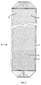
На фиг. 2 схематически представлен вид спереди перегородки, которая образует часть каналов в каталитической реакционной секции настоящего изобретения. In FIG. 2 is a schematic front view of a septum that forms part of the channels in the catalytic reaction section of the present invention.
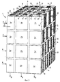
На фиг. 3 схематически представлено трехмерное изображение с расчленением элементов каталитического реактора, собранного в соответствии с настоящим изобретением. In FIG. 3 schematically shows a three-dimensional image with a dismemberment of elements of a catalytic reactor assembled in accordance with the present invention.
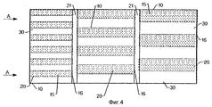
На фиг. 4 представлено поперечное сечение по 4 - 4 фиг. 3. In FIG. 4 is a cross-sectional view along 4-4 of FIG. 3.
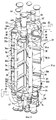
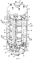
На фиг. 5 схематически представлен общий вид каталитического реактора настоящего изобретения с компоновкой реакторных труб в форме звезды. In FIG. 5 is a schematic perspective view of the catalytic reactor of the present invention with a star-shaped reactor tube arrangement.
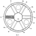
На фиг. 6 представлено поперечное сечение компоновки реактора, представленного на фиг. 5. In FIG. 6 is a cross-sectional view of the reactor arrangement of FIG. 5.
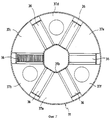
На фиг. 7 представлено поперечное сечение альтернативной внутренней компоновки реактора на фиг. 5. In FIG. 7 is a cross-sectional view of an alternative internal arrangement of the reactor of FIG. 5.
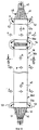
На фиг. 8 схематически представлено продольное сечение типичной каталитической реакционной трубы, образующей компоновку в виде звезды на фиг. 5. In FIG. 8 is a schematic longitudinal sectional view of a typical catalytic reaction tube forming a star arrangement in FIG. 5.
На фиг. 9 представлено поперечное сечение по длине 6 - 6 фиг. 8. In FIG. 9 shows a cross section along the length 6-6 of FIG. eight.
На фиг. 10 схематически представлен перспективный вид каталитического реактора настоящего изобретения с компоновкой реакционных труб многоугольной формы. In FIG. 10 is a schematic perspective view of the catalytic reactor of the present invention with a polygonal-shaped reaction tube arrangement.
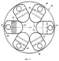
На фиг. 11 представлено поперечное сечение по линии 11 - 11 фиг. 10. In FIG. 11 is a cross-sectional view taken along line 11-11 of FIG. ten.
На фиг. 12 представлено поперечное сечение по линии 12 - 12 фиг. 10. In FIG. 12 is a cross-sectional view taken along line 12-12 of FIG. ten.
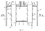
На фиг. 13 представлен схематически частичный продольный разрез альтернативной компоновки реакционных труб согласно изобретению. In FIG. 13 is a schematic partial longitudinal sectional view of an alternative arrangement of reaction tubes according to the invention.
На фиг. 14 представлено сечение по линии 14 - 14 фиг. 13. In FIG. 14 is a sectional view taken along line 14-14 of FIG. 13.
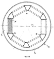
На фиг. 15 представлено поперечное сечение другой многоугольной компоновки реактора согласно изобретению. In FIG. 15 is a cross-sectional view of another polygonal arrangement of a reactor according to the invention.
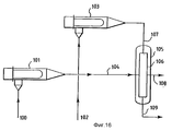
На фиг. 16 представлена диаграмма потоков способа дегидрирования согласно изобретению. In FIG. 16 is a flow chart of a dehydrogenation process according to the invention.
В соответствии с его конструкцией реактор согласно изобретению обладает тем достоинством, что в нем могут поддерживаться простыми средствами желаемые температурные профили, включая изотермический или условия обратного градиента температур, во время прохождения реагентов через реактор с помощью теплоносителя. In accordance with its construction, the reactor according to the invention has the advantage that it can be maintained by simple means the desired temperature profiles, including isothermal or reverse temperature gradient conditions, during the passage of the reactants through the reactor using a coolant.
В способе и реакторном устройстве могут быть использованы гомогенные или гетерогенные катализаторы. Гомогенные катализаторы обычно представляют собой жидкие катализаторы, которые протекают по реакционным каналам вместе с реагентами и отделяются для извлечения и рециклизации вне реакционной зоны. Конструкция реактора обеспечивает особые преимущества для гетерогенных катализаторов, которые обычно удерживаются внутри реакционных каналов волнистыми перегородками и проницаемыми участками, которые удерживают катализатор, но позволяют потоку реагентов пройти через них. В большинстве случаев гетерогенный катализатор представляет собой материал в виде частиц, удерживаемых между перегородками, и реактор может быть сконструирован таким образом, чтобы обеспечить непрерывную подачу и отвод частиц материала, когда реактор находится в работе. Homogeneous or heterogeneous catalysts may be used in the method and reactor device. Homogeneous catalysts are usually liquid catalysts that flow through the reaction channels together with the reagents and are separated for extraction and recycling outside the reaction zone. The design of the reactor provides particular advantages for heterogeneous catalysts, which are usually held inside the reaction channels by wavy partitions and permeable sections that hold the catalyst but allow the flow of reagents to pass through them. In most cases, a heterogeneous catalyst is a material in the form of particles held between partitions, and the reactor can be designed to provide a continuous supply and removal of particles of material when the reactor is in operation.
Тип и детали конструкции реактора, рассматриваемые в практике изобретения, будут лучше поняты со ссылкой на чертежи. The type and design details of the reactor considered in the practice of the invention will be better understood with reference to the drawings.
На фиг. 1 схематически представлено сечение каталитического реактора, сконструированного для проведения каталитической реакции с жидким реагентом при использовании теплообмена через стенку с теплоносителем для поддержания благоприятных температур реакции при прохождении жидкого реагента через реакционную секцию. Для этой цели секция каталитической реакции представляет собой звезду из параллельных перегородок 10 типа представленных на фиг. 2. Каждая перегородка 10 имеет центральную часть 12, которая образует наклонные волнистости 13. Предпочтительно каждая перегородка 10 также содержит однородные кромки 11, которые облегчает объединение множества перегородок в каналы. Снова ссылаясь на фиг. 1, каждая перегородка 10 накладывается на соседние перегородки 10 с образованием двух систем циркуляции, первой - cистемы A - для прохождения реакционной жидкости и второй - системы B - для прохождения вспомогательной жидкости. Вместе фиг. 1 и 2 определяют особые системы циркуляции A и B, в которых реакционная жидкость и жидкий теплоноситель соответственно протекают в поперечных направлениях, т.е. перпендикулярно и через чередующиеся каналы, образованные между соседними перегородками 10. In FIG. 1 is a schematic cross-sectional view of a catalytic reactor designed to carry out a catalytic reaction with a liquid reagent using heat transfer through a wall with a coolant to maintain favorable reaction temperatures when the liquid reagent passes through the reaction section. For this purpose, the catalytic reaction section is a star of
Подходящие перегородки для изобретения будут представлять собой любые перегородки, обеспечивающие высокую скорость теплопереноса и которые легко складываются в стабильный волнистый рисунок. Перегородки могут быть сформированы кривой или другой конфигурации, но плоские перегородки обычно являются предпочтительными для целей упаковки. Тонкие перегородки являются предпочтительными и обычно имеют толщину 1 - 2 мм. Перегородки обычно выполнены из железных или нежелезных сплавов, таких как нержавеющая сталь. Suitable partitions for the invention will be any partitions providing a high heat transfer rate and which easily fold into a stable wavy pattern. Partitions may be formed by a curve or other configuration, but flat partitions are usually preferred for packaging purposes. Thin partitions are preferred and usually have a thickness of 1 to 2 mm. Partitions are usually made of iron or non-ferrous alloys such as stainless steel.
Ссылаясь снова на фиг. 2, вариация волнистой компоновки является предпочтительным способом контроля температурного профиля. Компоновка перегородок на фиг. 2 представляет собой типичный рисунок волнистости для экзотермического и эндотермического процесса. Для поддержания практически изотермического или возрастающего температурного профиля в такой предпочтительной компоновке теплоноситель течет вниз через волнистости с одной стороны перегородки, а поток реагента течет горизонтально поперек с противоположной стороны перегородки. На верхнем впускном конце угол наклона волнистостей является маленьким, т.е. основное направление волнистостей приближается к параллельной ориентации с потоком жидкого теплоносителя. На нижнем конце перегородки, где выходит жидкий теплоноситель, угол наклона волнистостей является широким для увеличения относительного теплопереноса, т. е. основное направление волнистостей приближается к перпендикулярному или поперечному по отношению к потоку теплоносителя. Углы наклона волнистости могут быть в интервале от больше 0o до менее 90o. Обычно угол наклона волнистости от входного до выпускного сечения перегородки будет находиться в интервале от примерно 10 до 80o, а более типично в интервале от примерно 15 до 60o. В предпочтительном варианте компоновки перегородки будут иметь угол менее 30o у впускного конца перегородки и угол более 35o у выпускного конца перегородки. Переменная волнистость может быть сформирована в непрерывной секции перегородки или секция перегородок типа, показанного на фиг. 2, может быть изготовлена из нескольких перегородок, имеющих волнистости с различными углами наклона.Referring again to FIG. 2, variation of the wavy arrangement is the preferred method for controlling the temperature profile. The arrangement of the partitions in FIG. 2 is a typical waviness pattern for an exothermic and endothermic process. To maintain a substantially isothermal or increasing temperature profile in such a preferred arrangement, the coolant flows downward through the undulations on one side of the partition, and the reagent flow flows horizontally across from the opposite side of the partition. At the upper inlet end, the slope of the undulations is small, i.e. the main direction of the undulations approaches a parallel orientation with the flow of liquid coolant. At the lower end of the partition where the liquid coolant exits, the angle of inclination of the undulations is wide to increase the relative heat transfer, i.e., the main direction of undulations approaches the perpendicular or transverse with respect to the flow of coolant. The slope angles of the undulation can be in the range from greater than 0 ° to less than 90 ° . Typically, the slope angle of the undulation from the inlet to the outlet section of the partition will be in the range of from about 10 to 80 ° , and more typically in the range of from about 15 to 60 ° . In a preferred embodiment, the arrangement of the partition will have an angle of less than 30 o at the inlet end of the partition and an angle of more than 35 o at the outlet end of the partition. Variable undulations may be formed in a continuous partition section or a partition section of the type shown in FIG. 2 can be made of several partitions having undulations with different angles of inclination.
Волнистые перегородки могут быть разделены промежутками или расположены против соседних перегородок с образованием чередующихся каналов для потоков. Узкие промежутки между перегородками являются предпочтительными для получения максимальной поверхности теплопереноса. Предпочтительно волнистый рисунок должен быть повернут в обратном направлении между соседними перегородками в секции реактора. Таким образом, обычный рисунок в елочку на лицевых поверхностях противоположных волнистых перегородок будет простираться в противоположных направлениях и противоположные поверхности перегородок могут быть приведены в контакт друг с другом с образованием каналов для потоков и обеспечением структурной опоры для секций перегородок. Wavy partitions can be separated by gaps or located against adjacent partitions with the formation of alternating channels for flows. Narrow gaps between the partitions are preferred to obtain a maximum heat transfer surface. Preferably, the wavy pattern should be rotated in the opposite direction between adjacent baffles in the reactor section. Thus, the usual herringbone pattern on the front surfaces of opposing wavy partitions will extend in opposite directions and the opposite surfaces of the partitions can be brought into contact with each other to form flow channels and provide structural support for the partition sections.
Предпочтительно система A, в которой циркулирует поток жидких реагентов, содержит гетерогенный катализатор в форме частиц. Частицы катализатора обычно представляют собой гранулы маленького размера. Частицы могут иметь любую форму, но обычно они являются маленькими сферами или цилиндрами. Preferably, system A, in which a stream of liquid reactants circulates, contains a heterogeneous particulate catalyst. The catalyst particles are typically small granules. Particles can be of any shape, but they are usually small spheres or cylinders.
Кроме того, с целью загрузки и выгрузки катализатора, каталитический реактор может содержать средства для продвижения катализатора по каналам для реагентов. На фиг. 1 показаны такие средства 31, представленные схематически, для распределения катализатора в каналах A, а в его нижней части, средства 32, представленные схематически, для сбора катализатора во время операций перемещения. In addition, for the purpose of loading and unloading the catalyst, the catalytic reactor may contain means for advancing the catalyst through the channels for the reactants. In FIG. 1 shows such means 31, shown schematically, for distributing the catalyst in channels A, and in its lower part, means 32, shown schematically, for collecting the catalyst during moving operations.
На фиг. 3 и 4 очень схематично представлена компоновка реактора изобретения, показывающая обобщенную компоновку перегородок, объединенных в чередующиеся каналы (для упрощения чертежа волнистости не показаны). Для этой цели, как показано на фиг. 3, прикреплены подходящим способом, таким как сварка, распорки 14 вдоль боков перегородок 10 для формирования каналов 20, которые открыты с противоположных вертикальных боков реакторной установки для потока жидкого реагента, как показано стрелкой A (система A), и каналов 30, которые открыты в верхней и нижней частях реакторной установки для потока жидкого теплоносителя, как показано стрелками B (система B). In FIG. 3 and 4, the reactor arrangement of the invention is shown very schematically, showing a generalized layout of the partitions combined into alternating channels (not shown to simplify the drawing). For this purpose, as shown in FIG. 3 are attached by a suitable method, such as welding, to the
При протекании через частицы, находящиеся в каналах 20 системы A, жидкий реагент вступает в каталитическую реакцию, сопровождающуюся высвобождением или поглощением тепла. Функция теплоносителя, циркулирующего в системе B, заключается в переносе тепла, которое должно быть подведено к или удалено от жидкого реагента, чтобы поддержать благоприятные реакционные условия. When flowing through particles located in the
Такие условия снова могут включать изотермические условия во время циркуляции вышеупомянутого жидкого реагента в каталитическом реакторе или обратный температурный градиент. Жидкий теплоноситель является или газом или жидкостью в зависимости от конкретных рабочих условий каждого процесса. Характерное отношение теплопереноса для теплообменной перегородки установлено фундаментальным уравнением, выражающим перенос тепла между двумя жидкостями. Это отношение является следующим:
P=h•S•LMTD,
где P является количеством обменного тепла;
h является локальным или общим коэффициентом переноса тепла;
S является площадью теплообмена между жидкостями;
LMTD логарифмической средней разницей температур.Such conditions may again include isothermal conditions during the circulation of the aforementioned liquid reagent in the catalytic reactor or an inverse temperature gradient. The heat transfer fluid is either gas or liquid, depending on the specific operating conditions of each process. The characteristic heat transfer ratio for the heat exchange partition is established by the fundamental equation expressing heat transfer between two fluids. This relationship is as follows:
P = h • S • LMTD,
where P is the amount of heat exchanged;
h is a local or general heat transfer coefficient;
S is the heat transfer area between liquids;
LMTD logarithmic average temperature difference.
Логарифмическую среднюю разницу температур легко определить по желаемой разнице температур в любой точке вдоль перегородки. The logarithmic average temperature difference is easily determined by the desired temperature difference at any point along the partition.
Для серии волнистых перегородок, определяющих чередующиеся каналы для частиц катализатора и жидкого теплоносителя, локальный или общий коэффициент переноса тепла может быть рассчитан при использовании следующего уравнения:
h=f(a, e, dp),
где a является углом наклона волнистостей;
e является расстоянием между двумя перегородками 10;
dp является эквивалентным диаметром частиц катализатора.For a series of wavy baffles defining alternating channels for catalyst particles and a heat transfer fluid, the local or total heat transfer coefficient can be calculated using the following equation:
h = f (a, e, dp),
where a is the slope of the undulations;
e is the distance between the two
dp is the equivalent particle diameter of the catalyst.
Соответствующие величины h могут быть установлены путем моделирования или компьютерной обработки с использованием известных корреляций для установления коэффициентов переноса тепла на волнистых поверхностях и, когда имеются, через слой частиц. Корреляции для локализованного переноса тепла через слой частиц могут быть найдены в Lera, Ind. Eng. Chem., 42, 2498 (1950). Корреляции для переноса тепла вдоль волнистостей представлены в AIChE Symposium Series N 29 Heat Transfer Atlanta (1993). Corresponding values of h can be established by simulation or computer processing using known correlations to establish heat transfer coefficients on wavy surfaces and, when available, through a layer of particles. Correlations for localized heat transfer through a layer of particles can be found in Lera, Ind. Eng. Chem., 42, 2498 (1950). Correlations for heat transfer along undulations are presented in AIChE Symposium Series N 29 Heat Transfer Atlanta (1993).
Площадь обмена между жидким реагентом и вспомогательной жидкостью может быть рассчитана при использовании уравнения:
S = ε•n•l•L,
где ε является фактором корреляции для удлинения перегородок, возникшим в результате волнистостей; n равно количеству перегородок в контакте как с нагревающей, так и с реагирующей жидкостями;
l является шириной перегородки;
L является длиной перегородки.The exchange area between the liquid reagent and auxiliary liquid can be calculated using the equation:
S = ε • n • l • L,
where ε is the correlation factor for lengthening of the partitions resulting from undulations; n is equal to the number of partitions in contact with both the heating and the reacting liquids;
l is the width of the partition;
L is the length of the septum.
С помощью числа перегородок и характеристик волнистости, особенно угла наклона волнистости, изобретение обеспечивает средства для поддержания желаемых температурных условий в направлении потока жидкого реагента. By using the number of partitions and undulation characteristics, especially the undulation angle, the invention provides means for maintaining the desired temperature conditions in the direction of flow of the liquid reagent.
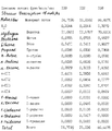
Как показано в варианте фиг. 3, средства контроля и поддержания температурных условий заключается в наличии отдельных секций 1a, 1b, 1c, 2a...4b, 4c теплообмена между жидким реагентом, циркулирующим в системе A, и теплоносителем, циркулирующим в системе B. На фиг. 3 отдельные секции теплообмена 1a, 1b, 1c, 2a...4b, 4c распределены в направлении потока жидкого реагента и в направлении потока жидкого теплоносителя таким образом, чтобы образовались ряды 1, 3, 3 и 4 и колонки a, b и c. При других компоновках настоящего изобретения эти отдельные секции теплообмена могут быть распределены только в направлении потока жидкого реагента или только в направлении потока жидкого теплоносителя. Суммарное количество отдельных реакционных секций, определенное для всего каталитического реактора фиг. 3, получают путем умножения количества рядов 1, 2, 3 и 4 на количество колонок a, b и c. Все секции теплообмена конкретного ряда имеют одинаковую вертикальную высоту и все секции теплообмена конкретной колонки имеют одинаковую горизонтальную ширину. As shown in the embodiment of FIG. 3, the means of monitoring and maintaining the temperature conditions is the presence of separate
Варьируя количество перегородок 10, как представлено на фиг. 3 и 4, возрастает теплообмен при большем количестве рядов или при меньшем количестве обозначенных буквами колонок за счет добавления площадей теплообмена между потоком реагента и потоком теплоносителя в каждой из вышеупомянутых секций. Для получения изменения теплообмена внутри секции 1a, 1b, 1c, 2a, 2b...4b, 4c, настоящее изобретение модифицирует каждую из этих секций предпочтительно за счет изменения угла наклона волнистостей. Как представлено на фиг. 2, угол наклона волнистостей 13 может быть более параллельным по отношению к направлению потока реагента, когда требуется высокий коэффициент переноса, и более поперечным к направлению потока жидкости в поверхностях теплообмена, когда требуется низкий коэффициент переноса. Varying the number of
Количество перегородок 10 может быть увеличено или уменьшено от входа к выходу жидкого реагента. На фиг. 4 показано, например, изменение секций теплообмена от большого количества к малому количеству перегородок вдоль 10 пути потока жидкого реагента. The number of
При использовании в изобретении гетерогенного катализатора каталитический реактор содержит средства для подачи катализатора 15 в каналы 20 системы A циркуляции жидкого реагента. Как показано на фиг. 3 и 4, средства, содержащие катализатор, могут состоять из решеток 16, помещенных на той или другой стороне каналов 20 в каждой поверхности теплообмена 1a, 1b, 1c, 2a... 4b, 4c. Эти решетки 16 закрывают всю ширину каналов 20, а размер ячеек каждой решетки меньше размера гранулы катализатора 15. When a heterogeneous catalyst is used in the invention, the catalytic reactor comprises means for supplying
Кроме того, когда в каталитическом реакторе настоящего изобретения используют множество отдельных секций теплообмена (1a, 1b, 1c, 2a...4b, 4c), предусматривают средства для смешивания и распределения жидкого реагента и-или теплоносителя. Как показано на фиг. 4, эти средства состоят из соединяющих распределительных промежутков 21, расположенных между вышеупомянутыми площадями теплообмена. In addition, when a plurality of individual heat transfer sections are used in the catalytic reactor of the present invention (1a, 1b, 1c, 2a ... 4b, 4c), means are provided for mixing and distributing the liquid reactant and / or heat transfer medium. As shown in FIG. 4, these means consist of connecting
На фиг. 5 и 6 схематически показан более характерный вариант полного реактора, смонтированного в соответствии с настоящим изобретением, реактор содержит множество реакционных труб, в каждой трубе имеется множество реакционных секций. В реакторе проводят каталитическую реакцию горизонтально текущего жидкого реагента в контролируемых температурных условиях при контакте через стенку с вертикальным потоком жидкого теплоносителя, обеспечивая при этом движение катализатора через реакционные трубы. In FIG. 5 and 6 schematically show a more typical embodiment of a complete reactor mounted in accordance with the present invention, the reactor contains a plurality of reaction tubes, each tube has a plurality of reaction sections. In the reactor, a catalytic reaction of horizontally flowing liquid reagent is carried out under controlled temperature conditions upon contact through the wall with a vertical flow of liquid coolant, while ensuring the movement of the catalyst through the reaction tubes.
Реактор состоит из сосуда кругового поперечного сечения, обозначенного в целом ссылкой 31 и показанного штрих-пунктирными линиями на фиг. 5. Сосуд 31 включает верхнее днище 32, например, полусферической формы, на котором установлено сопло 33 для подачи теплоносителя, и нижнее днище 34, например, полусферической формы, на котором установлено сопло 35 для отвода теплоносителя. The reactor consists of a vessel of circular cross section, indicated generally by
Как показано на фиг. 6, каталитическая установка включает две концентрические стенки 31a и 31b, которые установлены внутри сосуда 31 и между которыми установлены реакционные трубы 36. Реакционные трубы 36 являются вертикальными и распределены по конфигурации звезды между стенками 31a и 31b сосуда 31. На фиг. 7 показана вариация фиг. 6, в которой сосуд 31 состоит из наружной стенки 31a. Количество реакционных труб 36 предпочтительно является четным числом и на фиг. 5 - 7 равно шести. As shown in FIG. 6, the catalytic installation includes two
Боковые стенки реакционных труб 36 определяют часть зон питания 37a, 37c и 37e, установленных альтернативно между трубами 36 для распределения жидкого реагента и часть зон извлечения 37b, 37d и 37f, установленных альтернативно между трубами для отвода жидкого реагента. Верхние участки зон 37a, 37b. . . 37f скреплены горизонтальными перегородками 38, каждая установлена между реакционными трубами 36, а нижние участки зон 37a, 37b...37f закреплены горизонтальными перегородками 39, каждая установлена между реакционными трубами 36. Монтаж в виде звезды придает каждой зоне 37a, 37b...37f форму треугольной призмы с одной из вершин, ориентированной внутрь сосуда 31. В других вариантах, не показанных, каждая зона 37a...37f может быть разделена вертикальной стенкой на две полузоны с подразделенными частями зон, обеспечивающими одну зону подачи и одну зону извлечения. The side walls of the
Зоны питания 37a, 37c и 37e соединены средствами подачи жидкого реагента, которые в одной форме состоят из труб 42, в зоны извлечения 37b, 37d и 37f соединены средствами для выгрузки этого жидкого реагента, которые в одной форме представляют собой трубы 41. The
Как показано на фиг. 8 и 9, каждая реакционная труба 36 содержит множество параллельных перегородок 40. Перегородки 40 установлены перпендикулярно радиусу сосуда 31 и проходят в нижней части каждой из реакционных труб 36. Каждая перегородка 40 образует вместе с соседними перегородками 40 описанные ранее контуры циркуляции A и B. Каналы 43 содержат горизонтальный поток через контур A для прохода жидкого реагента, а каналы 44 содержат вертикальный поток через контур B для прохода жидкого теплоносителя. Контур A для циркуляции жидкого реагента также содержит частицы катализатора 45. Реактор содержит средства для прохода катализатора в контур A каждой реакционной трубы 36 и средства для отвода катализатора из контура A каждой реакционной трубы 36. Как показано в характерной компоновке на фиг. 5, трубы для подачи катализатора 46, число которых равно половине количества реакционных труб 36, снабжаются частицами свежего катализатора. Каждая труба 46 разделена на две подтрубы 46a и 46b, которые подают частицы катализатора в верхнюю часть реакционной трубы 20. As shown in FIG. 8 and 9, each
Множество труб 47 для выгрузки катализатора соединены каждая с нижней частью каждой реакционной трубы 36. Трубы 47 выходят непосредственно из сосуда 31 для улучшения удаления катализатора. Частицы катализатора могут быть удалены из реактора или периодически или непрерывно и возвращены в реактор после регенерации. A plurality of
На фиг. 5 и 8 показан диффузор 48 в верхней части каждой реакционной трубы для распределения катализатора в контуре A и коллектор 50 в нижней части труб 36 для отвода катализатора. Диффузоры 48 могут быть снабжены внутренними перегородками или волнистостями 13 для распределения катализатора. Каждый коллектор 50 включает внутренние перегородки или волнистости 51 для регулирования потока указанного катализатора в трубе 47. In FIG. 5 and 8, a
Каждая реакционная труба 36 включает в своей верхней части по крайней мере одно входное отверстие для ввода жидкого теплоносителя в контур B. Входное отверстие может быть просто отверстием. На рис. 5 и 8 показана реакционная труба 36, имеющая входное отверстие в форме двух боковых входных отверстий в форме чаши 52, каждое устроено с противоположных сторон соответствующей реакционной трубы 36. Входное отверстие 52 открыто внутрь сосуда 31, который содержит жидкий теплоноситель из сопла 33. Жидкий теплоноситель вводят в контур B через входное отверстие 52 через зону распределения 52a. Each
Каждая реакционная труба 36 обычно имеет в ее нижней части, по крайней мере, один коллектор для сбора жидкого теплоносителя из выпускного отверстия контура B. На фиг. 5 и 8 показана каждая реакционная труба 36, имеющая два боковых коллектора 53, каждый установлен с одной стороны реакционной трубы 36 для сбора жидкого теплоносителя из зоны извлечения 53a, которая соединена с каналами 44. Коллекторы соединены через открытый участок сосуда 31 ниже перегородки 39 выпускным соплом 35 для выгрузки жидкого теплоносителя. Each
Вариант, приведенный на фиг. 5 - 9, показывает каждую реакционную трубу 36, разделенную на множество реакционных секций 36a, 36b, 36c и 36d, которые соединены вместе с помощью промежуточных соединительных зон 54. Соединительные зоны 30 служат как коллекторы для повторного распределения для обеспечения раздельного прохода жидкого теплоносителя и катализатора между различными реакционными секциями 36a, 36b 36c и 36d. The embodiment of FIG. 5 to 9, shows each
В типичном варианте работы пропускают жидкий реагент, жидкий теплоноситель и возможно катализатор через реактор 31. Жидкий реагент подают в реактор 31 по трубам 42, пропускают в зоны питания 37а, 37c и 37e, затем пропускают горизонтально через две соединение реакционные трубы 36 по контуру A и направляют в зоны извлечения 37b, 37d и 37f. Жидкий реагент последовательно выводят по трубам 41. Жидкий теплоноситель вводят в верхнюю часть сосуда 31 через сопло 33, пропускают в реакционные трубы 36 через зоны впуска 52 и зоны распределения 52а. Жидкий теплоноситель проходит вертикально через реакционные трубы 36 по контуру B и выходит из реакционной трубы 36 через зоны извлечения 53a и коллекторы 53. Жидкий теплоноситель проходит в нижнюю часть сосуда 31 и выходит через сопло 35. Катализатор 45 подают в контур A каждой реакционной трубы 36 по трубам 46, по трубам 46a и 46b и через диффузор 48, где жидкий реагент контактирует с катализатором в контуре A. Через коллекторы 50 и трубы 47 периодически или непрерывно выводят катализатор из нижней части реакционной трубы 36. In a typical embodiment, a liquid reagent, a liquid coolant, and possibly a catalyst, are passed through a
Для поддержания желаемого температурного профиля при прохождении жидкого реагента через каждую реакционную секцию 36a, 36b, 36c и 36d в каждой секции варьируют угол наклона волнистости, определенный перегородками 40. Количество перегородок в каждой последовательно опускающейся вниз реакционной секции 36(a-d) увеличивается для постепенного добавления площади поверхности теплообмена между жидким реагентом и жидким теплоносителем вниз по длине каждой реакционной трубы 36. To maintain the desired temperature profile as the liquid reagent passes through each
Предпочтительно реакционные трубы 36 выдерживают под давлением внутри сосуда 31 за счет жидкого теплоносителя, рабочее давление жидкого теплоносителя обычно регулируют до величины, несколько большей, чем давление жидкого реагента. Для этой цели жидкий теплоноситель обычно подают в сосуд 31 и окружают им реакционные трубы 36. Preferably, the
В реакционном сосуде 31 реакционные трубы 36 могут быть установлены различным образом. Согласно другому типу компоновки, как показано на фиг. 10, реакционные трубы размещают таким образом, что перегородки 40 практически параллельны радиусу сосуда 55. Компоновка перегородок 40 параллельно радиусу сосуда 55 обеспечивает обычно многоугольную конфигурацию реакционных труб. Реакционные трубы образуют практически окружность внутри реакционного сосуда 55. In the
На фиг. 10 - 12 система трубопроводов и расположение каналов для подвода и извлечения жидких реагентов, жидких теплоносителей и катализаторов по существу подобным тем, что описаны для компоновки реактора на фиг. 5 - 9, и все детали реакционных труб также по существу подобным тем, что описаны. Частицы катализатора вводят в реактор 10 через сопло 56. Диффузоры 48' в верхней части реакционных труб 36' переносят катализатор в реакционные трубы через верхнюю головку 58. Сопла 57 выводят катализатор из реакционных труб 36' через коллектор описанного ранее типа и через нижнюю головку 59. Жидкий теплоноситель вводят в реактор 55 через сопло и заполняют им внутреннюю часть сосуда 55. Жидкий теплоноситель входит в реакционные трубы 36' через входное отверстие 52 и проходит через соседние реакционные секции с помощью соединительных зон 54'. Коллекторы на дне реакционных труб выгружают жидкий теплоноситель в сборный коллектор 61. Из коллектора 61 жидкий теплоноситель выгружают по трубам 62. Трубопроводы 63 собирают жидкий теплоноситель из труб 62 для вывода жидкого теплоносителя из сосуда 55. Дополнительные детали коллектора 61 и трубопровода 62 и 63 приведены на фиг. 12. Жидкий реагент протекает через сосуд 55 от впускного сопла 64 до выпускного сопла 65. Сопло 64 распределяет жидкий реагент и множество распределительных патрубков 66. Каждый распределительный патрубок 66 подводит жидкий реагент в распределительную камеру 67. Каждая распределительная камера 67 охватывает боковую часть каждой реакционной трубы 36' так, что ее лицевая поверхность обращена внутрь сосуда 55. Распределительные камеры 67 имеют закрытое дно, что усиливает поток жидкого реагента через каждую реакционную трубу 36' и в коллектор 68, который закрывает противоположную переднюю сторону каждой реакционной трубы 36'. Верхняя часть каждого коллектора 68 закрыта, чтобы направить выходящий поток жидкого реагента в трубопроводы 69 для сбора и выгрузки через сопло 65. In FIG. 10 to 12, the piping system and the arrangement of channels for supplying and removing liquid reagents, liquid coolants and catalysts substantially similar to those described for the arrangement of the reactor in FIG. 5 to 9, and all details of the reaction tubes are also substantially similar to those described. The catalyst particles are introduced into the
В другом варианте, показанном на фиг. 13 и 14, реакционные трубы 36' соединены в практически многоугольную форму и помещены в реакционный сосуд 55. Перегородки 70, показанные на фиг. 14, определяют внутреннее расстояние распределения 71 жидкого реагента. Как показано на фиг. 13, верхняя перегородка 72 и нижняя перегородка 73 образуют верхнюю и нижнюю границы пространства для распределения 71. Жидкий реагент вводят в пространство для распределения через верхнюю перегородку 72 с помощью сопла 64 и он перетекает из внутреннего пространства для распределения 71 в наружное пространство сбора 74. Наружное пространство для сбора 74 устраняет потребность в коллекторном трубопроводе и жидкий реагент выходит из сосуда непосредственно через открытое сопло 65 (не показано). В отличие от ранее приведенных конфигураций реактора вариант на фиг. 13 и 14 показывает жидкий реагент, окружающий реакционные трубы 36'. Перегородка 35 вместе с перегородкой 33 изолируют верхнюю часть сосуда 55 с образованием распределенной камеры для подачи жидкого теплоносителя во входные отверстия 52' ранее описанным образом. Жидкий теплоноситель снова выходит из реакционных труб 36' через коллектор и систему трубопроводов практически так же, как показано на фиг. 10 - 12. Любой поток катализатора в варианте фиг. 13 и 14 практически проходит так же, как описано ранее. In another embodiment shown in FIG. 13 and 14, the reaction tubes 36 'are connected in a substantially polygonal shape and placed in the
На фиг. 15 показана компоновка реакционных труб 35', которая объединяет впускное распределительное пространство фиг. 13 и 14 с коллекторами перегородками, показанными на фиг. 10 - 12. В компоновке, показанной на фиг. 15, любой поток катализатора снова проходит так же, как описано ранее. Что касается жидкого реагента, он протекает в центральную камеру 71, как показано на фиг. 13 и 14, и собирается и выводится из реакционных труб 36', как показано на фиг. 10 - 12. При компоновке реакционных труб, как показано на фиг. 15, поток жидкого теплоносителя через реактор можно контролировать с помощью двух различных компоновок трубопроводов и перегородок. Входящий жидкий теплоноситель может окружать реакционные трубы 36' и заполнять внутренность сосуда 55, в то время как коллекторная система, подобная представленной на фиг. 10 - 12, выводит поток жидкого теплоносителя. При другой компоновке перегородки, такие как представлены на фиг. 13 и 14, перекрывают верхний объем сосуда 55 для распределения входящего жидкого теплоносителя во входные отверстия 52', тогда как жидкий теплоноситель окружает реакционные трубы 36' и выводится из открытого нижнего объема без использования какого-либо коллектора или системы трубопроводов. In FIG. 15 shows an arrangement of reaction tubes 35 ′ that integrates the inlet distribution space of FIG. 13 and 14 with the manifold partitions shown in FIG. 10 to 12. In the arrangement shown in FIG. 15, any catalyst stream again flows as previously described. As for the liquid reagent, it flows into the
Каталитический риформинг является хорошо изученным процессом превращения углеводородов, применяемых в нефтеочистительной промышленности для улучшения октанового качества углеводородного сырья, основным продуктом риформинга является автомобильный бензин. Технология каталитического риформинга хорошо известна и не требует здесь подробного описания. Кратко, при каталитическом риформинге сырье смешивают с рециклизуемым потоком, содержащим водород, и контактируют с катализатором в реакционной зоне. Обычным сырьем для каталитического риформинга является нефтяная фракция, известная как нафталигроин и имеющая начальную точку кипения около 180oF (80oC) и конечную точку кипения около 400oF (205oC). Процесс каталитического риформинга особенно применим к обработке бензина прямой гонки, содержащего относительно большие количества нафтеновых и парафиновых углеводородов с практически прямой цепью, которые подвергают ароматизации через реакции дегидрирования и/или циклизации. Риформинг может быть определен как суммарный эффект, полученный при дегидрировании циклогексанов и дегидроизомеризации алкилциклопентанов с получением ароматики, дегидрировании парафинов с получением олефинов, дегидроциклизации парафинов и олефинов с получением ароматики, изомеризации н-парафинов, изомеризации алкилциклопарафинов с получением циклогексанов, изомеризации замещенной ароматики и гидрокрекинга парафинов. Дополнительная информация о процессах риформинга может быть найдена, например, в патентах США 4 119 526 /Peters et. al./, 4 409 095 /Peters/b 4 440 626 /Winter et. al/, содержание которых приводится здесь в качестве уровня техники.Catalytic reforming is a well-studied process of conversion of hydrocarbons used in the oil refining industry to improve the octane quality of hydrocarbons, the main product of reforming is gasoline. Catalytic reforming technology is well known and does not require a detailed description here. Briefly, in catalytic reforming, the feed is mixed with a recycled stream containing hydrogen and contacted with a catalyst in the reaction zone. A common feedstock for catalytic reforming is the petroleum fraction known as naphthaleigroin and having an initial boiling point of about 180 ° F (80 ° C) and an final boiling point of about 400 ° F (205 ° C). The catalytic reforming process is particularly applicable to the processing of straight race gasoline containing relatively large amounts of substantially straight chain naphthenic and paraffinic hydrocarbons that undergo aromatization through dehydrogenation and / or cyclization reactions. Reforming can be defined as the total effect obtained by dehydrogenation of cyclohexanes and dehydroisomerization of alkylcyclopentanes to obtain aromatics, dehydrogenation of paraffins to obtain olefins, dehydrocyclization of paraffins and olefins to obtain aromatics, isomerization of n-paraffins, isomerization of alkylcycloparaffins, and aromatic cycloferification . Further information on reforming processes can be found, for example, in US Pat. Nos. 4,119,526 / Peters et. al./, 4 409 095 / Peters /
Реакцию каталитического риформинга обычно проводят в присутствии частиц катализатора, состоящего из одного или нескольких благоприятных металлов VIII Группы (например, платины, иридия, родия, палладия), и галоида, объединенных на пористом носителе, таком как огнеупорный неорганический оксид. Галоидом обычно является хлор. В качестве носителя обычно используют оксид алюминия. Предпочтительными материалами из оксида алюминия являются гамма, эта и тета-оксиды алюминия, гамма- и эта-оксиды алюминия дают лучшие результаты. Важным свойством, относящимся к эксплуатационным характеристикам катализатора, является площадь поверхности носителя. Предпочтительно носитель должен иметь площадь поверхности от 100 до примерно 500 м2/г. Частицы обычно являются сферическими и имеют диаметр от примерно 1/16 до примерно 1/8 дюйма (1,5 - 3,1 мм), хотя они могут быть такими большими, как 1/4 дюйма (6,35 мм). Предпочтительно диаметр частиц катализатора составляет 1/6 дюйма (3,1 мм). Во время проведения реакции риформинга частицы катализатора дезактивируются в результате таких механизмов, как отложение кокса на частицах, т. е. после определенного периода времени использования способность частиц катализатора промотировать реакции риформинга снижается до уровня, при котором катализатор больше не является полезным. Катализатор должен быть снова кондиционирован или регенерирован перед его повторным использованием в процессе риформинга.The catalytic reforming reaction is usually carried out in the presence of catalyst particles consisting of one or more favorable Group VIII metals (e.g., platinum, iridium, rhodium, palladium) and a halogen combined on a porous support such as a refractory inorganic oxide. Halogen is usually chlorine. Alumina is usually used as a carrier. Preferred alumina materials are gamma, eta and theta alumina, gamma and eta alumina give better results. An important property related to the performance of the catalyst is the surface area of the carrier. Preferably, the carrier should have a surface area of from 100 to about 500 m 2 / g. Particles are typically spherical and have a diameter of from about 1/16 to about 1/8 inch (1.5 to 3.1 mm), although they can be as large as 1/4 inch (6.35 mm). Preferably, the particle diameter of the catalyst is 1/6 inch (3.1 mm). During the reforming reaction, the catalyst particles are deactivated as a result of mechanisms such as coke deposition on the particles, i.e., after a certain period of use, the ability of the catalyst particles to promote the reforming reactions decreases to a level at which the catalyst is no longer useful. The catalyst must be conditioned or regenerated again before being reused in the reforming process.
В предпочтительной форме в операции риформинга применяют зону реакции с движущимся слоем и зону регенерации. Настоящее изобретение применимо к зонам с движущимся слоем и со стационарным слоем. В операции с движущимся слоем частицы свежего катализатора подают в зону реакции под действием силы тяжести. Катализатор выводят из нижней части реакционной зоны и транспортируют в зону регенерации, где используют многостадийный процесс регенерации для повторного кондиционирования катализатора, чтобы восстановить его способность и промотировать реакцию. Катализатор проходит под действием силы тяжести через различные стадии регенерации и затем выводиться из зоны регенерации и подается в зону реакции. Движение катализатора через зоны часто упоминается как непрерывное, хотя на практике оно является полунепрерывным. Под полунепрерывным движением понимают повторный перенос относительно малых количеств катализатора в близко расположенные точки во времени. Система движущегося слоя имеет преимущество сохранения производительности при удалении или перемешивании катализатора. In a preferred form, a moving bed reaction zone and a regeneration zone are used in the reforming operation. The present invention is applicable to areas with a moving layer and with a stationary layer. In a moving bed operation, fresh catalyst particles are fed into the reaction zone by gravity. The catalyst is removed from the lower part of the reaction zone and transported to the regeneration zone, where a multi-stage regeneration process is used to re-condition the catalyst in order to restore its ability and promote the reaction. The catalyst passes under the influence of gravity through various stages of regeneration and then is removed from the regeneration zone and fed into the reaction zone. The movement of the catalyst through the zones is often referred to as continuous, although in practice it is semi-continuous. Semi-continuous motion is understood to mean the re-transfer of relatively small amounts of catalyst to closely spaced points in time. A moving bed system has the advantage of maintaining performance when removing or mixing the catalyst.
Другим предпочтительным процессом превращения углеводородов является алкилирование ароматических углеводородов. При алкилировании ароматики подходящим ароматическим углеводородным сырьем для настоящего изобретения являются различные ароматические субстраты. Такими субстратами могут быть бензол или алкилированные ароматические углеводороды, такие как толуол. Ациклическое углеводородное сырье или алкилирующий агент, которые могут быть использованы в зоне реакции алкилирования, также охватывают широкий круг углеводородов. Подходящие алкилирующие агенты включают моноолефины, диолефины, полиолефины, ацетиленовые углеводороды и другие замещенные углеводороды, но предпочтительно они являются C2-C4 - моноолефинами.Another preferred hydrocarbon conversion process is the alkylation of aromatic hydrocarbons. In aromatic alkylation, various aromatic substrates are suitable aromatic hydrocarbon feedstocks for the present invention. Such substrates may be benzene or alkyl aromatic hydrocarbons such as toluene. Acyclic hydrocarbon feedstocks or an alkylating agent that can be used in the alkylation reaction zone also cover a wide range of hydrocarbons. Suitable alkylating agents include monoolefins, diolefins, polyolefins, acetylene hydrocarbons and other substituted hydrocarbons, but preferably they are C 2 -C 4 monoolefins.
В зоне реакции алкилирования может быть использован широкий круг катализаторов. Предпочтительным катализатором для использования в настоящем изобретении является цеолитный катализатор. Катализатор настоящего изобретения обычно используют в сочетании со связующим из огнеупорного неорганического оксида. Предпочтительными связующими являются оксиды алюминия и оксид кремния. Предпочтительными катализаторами алкилирования являются цеолит типа Y, имеющий связующее из оксида алюминия или оксида кремния, или бетацеолит, имеющий связующее из оксида алюминия или оксида кремния. Цеолит будет присутствовать в количестве по крайней мере 50 мас.% катализатора, а более предпочтительно в количестве по крайней мере 70 мас.% катализатора. A wide range of catalysts can be used in the alkylation reaction zone. A preferred catalyst for use in the present invention is a zeolite catalyst. The catalyst of the present invention is usually used in combination with a refractory inorganic oxide binder. Preferred binders are alumina and silica. Preferred alkylation catalysts are type Y zeolite having an alumina or silica binder, or betaceolite having an alumina or silica binder. Zeolite will be present in an amount of at least 50 wt.% Of the catalyst, and more preferably in an amount of at least 70 wt.% Of the catalyst.
Зона реакции алкилирования может работать в широком интервале рабочих условий. Температуры обычно находятся в интервале от 100 до 325oC, предпочтительным является интервал от 150 до 275oC. Давления также могут варьировать в широком интервале от примерно 1 до 130 атм. Поскольку в реакционной зоне обычно предпочтительными являются условия жидкой фазы, давление должно быть достаточным для поддержания реагентов в такой фазе и обычно оно находится в интервале от 10 до 50 атм. Реагенты обычно проходят через зону алкилирования с массовой скоростью, достаточной для получения часовой объемной скорости жидкости от 0,5 до 50 час-1 и особенно 1 - 10 час-1.The alkylation reaction zone can operate in a wide range of operating conditions. Temperatures are usually in the range of from 100 to 325 ° C., a range of from 150 to 275 ° C. is preferred. The pressures can also vary in a wide range from about 1 to 130 atm. Since the conditions of the liquid phase are usually preferred in the reaction zone, the pressure should be sufficient to maintain the reactants in this phase, and usually it is in the range from 10 to 50 atm. Reagents usually pass through the alkylation zone with a mass velocity sufficient to obtain a fluid hourly space velocity of from 0.5 to 50 h -1 and especially 1 to 10 h -1 .
Зона алкилирования обычно работает таким образом, чтобы получить по существу, полное превращение алкилирующего агента в моноалкилат и полиалкилат. Для достижения такого эффекта в зону реакции обычно загружают дополнительный ароматический субстрат. Так, сырьевую смесь вводят в зону реакции с постоянной скоростью и при молярном отношении от примерно 1:1 до 20:1 ароматического субстрата к алкилирующему агенту, предпочтительным является отношение от примерно 2:1 до 10:1. В результате помимо продукта обычно будет иметься значительное количество непрореагировавшего ароматического субстрата, который удаляют из потока продукта из зоны реакции алкилирования. Дополнительные детали процесса алкилирования ароматики могут быть найдены в патенте США 5 177 285, содержание которого здесь приведено в качестве уровня техники. The alkylation zone usually works in such a way as to obtain essentially complete conversion of the alkylating agent to monoalkylate and polyalkylate. To achieve this effect, an additional aromatic substrate is usually loaded into the reaction zone. Thus, the feed mixture is introduced into the reaction zone at a constant rate and with a molar ratio of from about 1: 1 to 20: 1 of the aromatic substrate to the alkylating agent, a ratio of from about 2: 1 to 10: 1 is preferred. As a result, in addition to the product, there will usually be a significant amount of unreacted aromatic substrate that is removed from the product stream from the alkylation reaction zone. Additional details of the aromatic alkylation process can be found in US Pat. No. 5,177,285, the contents of which are incorporated herein by reference.
Каталитическое дегидрирование является другим примером эндотермического процесса, в котором целесообразно использовать способ и устройство настоящего изобретения. Кратко, при каталитическом дегидрировании сырье смешивают с рециклизованным потоком, содержащим водород, и конденсируют с катализатором в зоне реакции. Сырьем для каталитического дегидрирования обычно являются нефтяные фракции, содержащие парафины, имеющие 3 - 18 атомов углерода. Конкретное сырье обычно будет содержать легкие или тяжелые парафины. Например, обычное сырье для получения тяжелых продуктов дегидрирования будет содержать парафины, имеющие 10 или более атомов углерода. Процесс каталитического дегидрирования особенно применим к обработке углеводородного сырья, содержащего по существу парафиновые углеводороды, которые подвергают реакции дегидрирования, получая в результате олефиновые углеводородные соединения. Catalytic dehydrogenation is another example of an endothermic process in which it is advisable to use the method and apparatus of the present invention. Briefly, in catalytic dehydrogenation, the feed is mixed with a recycled stream containing hydrogen and condensed with a catalyst in the reaction zone. Catalytic dehydrogenation feedstocks are typically petroleum fractions containing paraffins having 3 to 18 carbon atoms. Specific feedstocks will typically contain light or heavy paraffins. For example, conventional feedstocks for heavy dehydrogenation products will contain paraffins having 10 or more carbon atoms. The catalytic dehydrogenation process is particularly applicable to the processing of hydrocarbon feedstocks containing substantially paraffinic hydrocarbons that undergo a dehydrogenation reaction to produce olefinic hydrocarbon compounds.
Реакцию каталитического дегидрирования обычно проводят в присутствии частиц катализатора, содержащих благородные металлы VIII Группы (например, платину, иридий, родий, палладий), объединенные с пористым носителем, таким как огнеупорный неорганический оксид. Обычно в качестве носителя используют оксид алюминия. Предпочтительные материалы из оксида алюминия известны как гамма, эта и тета-оксиды-алюминия, гамма и эта-оксиды алюминия дают лучшие результаты. Предпочтительно носитель будет иметь площадь поверхности от 100 примерно 500 м2/г. Частицы обычно являются сферическими и имеют диаметр от примерно 1/16 до примерно 1/8 дюйма (1,5 - 3,1 мм), хотя они могут быть такими большими, как 1/4 дюйма (6,35 мм). Обычно частицы катализатора имеют концентрацию хлорида между 0,5 и 3 мас.%. Во время проведения реакции дегидрирования частицы катализатора дезактивируются в результате отложения кокса и требуют регенерации подобно той, что описана для процесса реформинга: следовательно, в предпочтительной форме процесс дегидрирования снова будет применять зону реакции с движущимся слоем и зону регенерации.The catalytic dehydrogenation reaction is usually carried out in the presence of catalyst particles containing Group VIII noble metals (e.g., platinum, iridium, rhodium, palladium) combined with a porous carrier such as a refractory inorganic oxide. Typically, alumina is used as a carrier. Preferred alumina materials are known as gamma, eta and theta aluminas, gamma and eta aluminas give better results. Preferably, the carrier will have a surface area of from about 100 to about 500 m 2 / g. Particles are typically spherical and have a diameter of from about 1/16 to about 1/8 inch (1.5 to 3.1 mm), although they can be as large as 1/4 inch (6.35 mm). Typically, the catalyst particles have a chloride concentration between 0.5 and 3 wt.%. During the dehydrogenation reaction, the catalyst particles are deactivated as a result of coke deposition and require regeneration similar to that described for the reforming process: therefore, in a preferred form, the dehydrogenation process will again use the moving bed reaction zone and the regeneration zone.
Условия дегидрирования включают температуру от примерно 400oC до примерно 900oC, давление от примерно 0,01 до 10 атм и часовую объемную скорость жидкости (LHSV) от примерно 0,1 до 100 час-1. Обычно для нормальных парафинов для сравнимых конверсий требуются более высокие температуры для более низких молекулярных масс. Давление в зоне дегидрирования поддерживают по возможности низким, соответствующим ограничениям оборудования, чтобы максимально повысить преимущества химического равновесия. Предпочтительные условия дегидрирования в способе настоящего изобретения включают температуру от примерно 400 - 700oC, давление от примерно 0,1 до 5 атм и часовую объемную скорость жидкости от примерно 0,1 до 100 час-1.Dehydrogenation conditions include a temperature of from about 400 ° C. to about 900 ° C., a pressure of from about 0.01 to 10 atmospheres, and a liquid hourly space velocity (LHSV) of from about 0.1 to 100 h −1 . Generally, normal paraffins for comparable conversions require higher temperatures for lower molecular weights. The pressure in the dehydrogenation zone is kept as low as possible, consistent with equipment limitations, to maximize the benefits of chemical equilibrium. Preferred dehydrogenation conditions in the method of the present invention include a temperature of from about 400 to 700 ° C., a pressure of from about 0.1 to 5 atmospheres, and a fluid hourly space velocity of from about 0.1 to 100 h −1 .
Поток, выходящий из зоны дегидрирования, обычно будет содержать непревращенные дегидрируемые углеводороды, водород и продукты реакции дегидрирования. Этот выходящий поток обычно охлаждают и направляют в зону отделения водорода, чтобы отделить обогащенную водородом паровую фазу от обогащенной углеводородами жидкой фазы. Обычно обогащенную углеводородами жидкую фазу далее разделяют с помощью или подходящего селективного адсорбента, селективного растворителя, селективной реакции или реакций, или с помощью подходящей схемы фракционирования, непревращенные дегидрируемые углеводороды извлекают и они могут быть рециклизованы в зону дегидрирования. Продукты реакций дегидрирования извлекают и в виде готовых продуктов или в качестве промежуточных продуктов для получения других соединений. The stream leaving the dehydrogenation zone will usually contain unconverted dehydrogenated hydrocarbons, hydrogen, and dehydrogenation reaction products. This effluent is usually cooled and directed to a hydrogen separation zone to separate the hydrogen-rich vapor phase from the hydrocarbon-rich liquid phase. Typically, the hydrocarbon-rich liquid phase is further separated by either an appropriate selective adsorbent, a selective solvent, a selective reaction or reactions, or by using a suitable fractionation scheme, unconverted dehydrogenated hydrocarbons are recovered and they can be recycled to the dehydrogenation zone. The products of dehydrogenation reactions are recovered either as finished products or as intermediates for the preparation of other compounds.
Дегидрируемые углеводороды могут быть смешаны с газообразным разбавителем до, во время или после прохождения зоны дегидрирования. Материалом разбавителя может быть водород, пар, метан, диоксид углерода азот, аргон и т. п. и их смеси. Предпочтительно разбавителем является водород. Обычно при использовании в качестве разбавителя газообразного разбавителя он может быть использован в количестве, достаточном для обеспечения молярного отношения газообразного разбавителя к углеводороду от примерно 0,1 до примерно 20, лучшие результаты получены, когда молярное отношение находится в интервале от примерно 0,5 до 10. Разбавляющий поток водорода, прошедший зону дегидрирования, обычно рециклизуют, водород отделяют от потока, выходящего из зоны дегидрирования в зоне отделения водорода. Dehydrogenated hydrocarbons may be mixed with a gaseous diluent before, during, or after passing through the dehydrogenation zone. The diluent material may be hydrogen, steam, methane, carbon dioxide, nitrogen, argon, etc., and mixtures thereof. Preferably, the diluent is hydrogen. Typically, when a gaseous diluent is used as a diluent, it can be used in an amount sufficient to provide a molar ratio of the gaseous diluent to hydrocarbon of from about 0.1 to about 20, better results are obtained when the molar ratio is in the range of from about 0.5 to 10 The diluting hydrogen stream passing through the dehydrogenation zone is usually recycled, hydrogen is separated from the stream leaving the dehydrogenation zone in the hydrogen separation zone.
Вода или материал, который разлагается в условиях дегидрирования с образованием воды, такой как спирт, альдегид, простой эфир или кетон, например, могут быть добавлены в зону дегидрирования или непрерывно или периодически в таком количестве, чтобы обеспечить, считая на основу эквивалентной воды, примерно от 1 до 20000 млн-1 потока углеводородного сырья. Добавление примерно 1 - 10000 млн-1 воды дает лучшие результаты при дегидрировании парафинов, имеющих от 6 до 30 и более атомов углерода. Дополнительную информацию, относящуюся к операции дегидрирования, катализаторам, рабочим условиям и оборудованию способа можно найти в патентах США 4 677 327, 4 880 764 и 5 087792, содержание которых приведено здесь в качестве уровня техники.Water or a material that decomposes under dehydrogenation conditions to form water, such as alcohol, aldehyde, ether or ketone, for example, can be added to the dehydrogenation zone either continuously or intermittently in such an amount as to provide, based on equivalent water, approximately from 1 million to 20000 -1 hydrocarbon feed stream. Adding about 1 - 10000 million -1 water gives best results when dehydrogenating paraffins having from 6 to 30 or more carbon atoms. Additional information related to the dehydrogenation operation, catalysts, process conditions, and process equipment can be found in US Pat. Nos. 4,677,327, 4,880,764 and 5,087,792, the contents of which are incorporated herein by reference.
Пример. Изучали эффект использования способа и реакционной установки настоящего изобретения для поддержания изотермических условий в процессе превращения углеводородов для дегидрирования парафинов. Моделирование, основанное на способности настоящего изобретения поддерживать изотермические условия, было проведено с исходным сырьем, имеющим состав, приведенный в таблице. Изотермические условия, которые явились результатом настоящего изобретения, были смоделированы в процессе дегидрирования, как представлено на фиг. 16. Example. We studied the effect of using the method and reaction unit of the present invention to maintain isothermal conditions in the process of conversion of hydrocarbons for the dehydrogenation of paraffins. Modeling based on the ability of the present invention to maintain isothermal conditions was carried out with a feedstock having the composition shown in the table. The isothermal conditions resulting from the present invention were modeled during the dehydrogenation process as shown in FIG. 16.
В этом моделирующем процессе сырье, подаваемое по линии 100 и имеющее состав, приведенный в таблице, пропускают в нагреватель 101, в котором температуру сырья повышают от примерно 600oF (316oC) до 850oF (454oC). В то же время теплоноситель, имеющий тот же относительный состав, что и сырье 100 подают по линии 102 в нагреватель 103. Нагреватель 103 повышает температуру теплоносителя примерно до 890oF (477oC).In this modeling process, the feed supplied through
По линии 104 подают нагретое сырье в реактор 105, который направляет сырье в трубчатый теплообменник 106, сконструированный в соответствии с настоящим изобретением. Реактор 105 имеет конструкцию, чтобы пропустить сырье через контур A, содержащий типичный катализатор дегидрирования, состоящий из пластины на носителе из оксида алюминия. По линии 107 подают теплоноситель из нагревателя 103 в реактор 105, в котором проходит теплоноситель вниз через трубчатый теплообменник 106, как описано ранее в отношении контура B. Процесс моделирования трубчатого реактора 106 основан на использовании трубчатого теплообменника 106, имеющего три слоя катализатора, вертикальную высоту примерно 1,5 м и ширину около 100 мм. Перегородки, определяющие каналы, которые чередуются между катализатором и сырьем и жидким теплоносителем, имеют толщину около 1,2 мм волнистости с глубиной около 10 мм и ширину около 270 мм. Перегородки размещены вблизи друг к другу при чередующемся рисунке волнистостей, так, что пики волнистостей находятся в контакте. Реактор работает при среднем давлении около 20 фунт/дюйм2/ 1,406 кг/см2 в обоих контурах A и B. Суммарное падение давления в системе для жидкого реагента составляет примерно 2 фунт/дюйм2 /0,141 кг/см2. Теплообмен через стенку жидкого реагента с теплоносителем обеспечивает среднюю температуру на выходе около 850oF (454oC).
Процесс превращенного реагента и поток теплоносителя выводят из процесса. Поток продукта 108, имеющий состав, приведенный в таблице, выводят из реактора при температуре около 850oF (454oC). По линии 109 подают теплоноситель из реактора с температурой около 870oF (466oC). Сравнение потоков 100 и 108 показывает конверсию C10-C14 - парафинов в соответствующие олефины.The process of the converted reagent and the coolant stream are removed from the process. The
Claims (34)
05.07.93 по пп.1, 10, 13, 20, 30;
13.08.93 по всем зависимым пунктам.Priority on points:
07/05/93 according to claims 1, 10, 13, 20, 30;
08/13/93 for all dependent items.
Applications Claiming Priority (7)
| Application Number | Priority Date | Filing Date | Title |
|---|---|---|---|
| FR9308210 | 1993-07-05 | ||
| FR9308210A FR2707186B1 (en) | 1993-07-05 | 1993-07-05 | Isothermal catalytic reactor. |
| FR9309967 | 1993-08-13 | ||
| FR9309966 | 1993-08-13 | ||
| FR9309967A FR2708872B1 (en) | 1993-08-13 | 1993-08-13 | Isothermal catalytic unit intended to produce a catalytic reaction. |
| FR9309966A FR2708871B1 (en) | 1993-08-13 | 1993-08-13 | Isothermal catalytic unit. |
| PCT/EP1994/002177 WO1995001834A1 (en) | 1993-07-05 | 1994-07-02 | Process and apparatus for controlling reaction temperatures |
Publications (2)
| Publication Number | Publication Date |
|---|---|
| RU96101993A RU96101993A (en) | 1998-05-10 |
| RU2136358C1 true RU2136358C1 (en) | 1999-09-10 |
Family
ID=27252770
Family Applications (1)
| Application Number | Title | Priority Date | Filing Date |
|---|---|---|---|
| RU96101993A RU2136358C1 (en) | 1993-07-05 | 1994-07-02 | Method and device for temperature monitoring (modifications) and method for catalytic dehydrogeneration of hydrocarbons |
Country Status (11)
| Country | Link |
|---|---|
| EP (3) | EP0766999B1 (en) |
| JP (1) | JPH09508565A (en) |
| KR (1) | KR960703665A (en) |
| CN (2) | CN1051249C (en) |
| AT (3) | ATE206069T1 (en) |
| CA (1) | CA2166564A1 (en) |
| DE (3) | DE69413691T2 (en) |
| ES (1) | ES2123150T3 (en) |
| RU (1) | RU2136358C1 (en) |
| TW (1) | TW330989B (en) |
| WO (1) | WO1995001834A1 (en) |
Cited By (3)
| Publication number | Priority date | Publication date | Assignee | Title |
|---|---|---|---|---|
| WO2011078743A2 (en) * | 2009-12-22 | 2011-06-30 | Pizhonkov Alexey Germanovich | Plant for processing hydrocarbon-containing liquid media and method for operating same |
| RU2466786C2 (en) * | 2011-01-28 | 2012-11-20 | Андрей Юрьевич Беляев | Converter and element of converter heat pipe |
| RU2643366C1 (en) * | 2017-08-30 | 2018-02-01 | Акционерное общество "Специальное конструкторско-технологическое бюро "Катализатор" | Technological scheme of dehydration device of paraffin hydrocarbons c3-c5 (versions) |
Families Citing this family (38)
| Publication number | Priority date | Publication date | Assignee | Title |
|---|---|---|---|---|
| US5540899A (en) * | 1994-12-22 | 1996-07-30 | Uop | BI-directional control of temperatures in reactant channels |
| US5853674A (en) * | 1996-01-11 | 1998-12-29 | International Fuel Cells, Llc | Compact selective oxidizer assemblage for fuel cell power plant |
| DE19754185C1 (en) * | 1997-12-06 | 1999-02-04 | Deg Engineering Gmbh | Chemical catalytic reactor assembly has cushion-like internal heat exchangers |
| DE19848208A1 (en) * | 1998-10-20 | 2000-04-27 | Deg Engineering Gmbh | Reactor for the catalytic conversion of reaction media, especially gaseous reaction media |
| US6380324B1 (en) | 1999-01-26 | 2002-04-30 | Rohm And Haas Company | Reduction of polymer fouling on reactor surface in a continuous process for preparing polymers |
| FR2790680B1 (en) * | 1999-03-09 | 2001-06-08 | Packinox Sa | CATALYTIC REACTOR WITH PLATE BEAM |
| US7033553B2 (en) | 2000-01-25 | 2006-04-25 | Meggitt (Uk) Limited | Chemical reactor |
| US6921518B2 (en) | 2000-01-25 | 2005-07-26 | Meggitt (Uk) Limited | Chemical reactor |
| US7022294B2 (en) | 2000-01-25 | 2006-04-04 | Meggitt (Uk) Limited | Compact reactor |
| JP4069570B2 (en) * | 2000-03-16 | 2008-04-02 | 株式会社デンソー | Exhaust heat exchanger |
| US7316804B2 (en) | 2001-08-02 | 2008-01-08 | Ineos Usa Llc | Flow reactors for chemical conversions with heterogeneous catalysts |
| DE10159816A1 (en) * | 2001-12-06 | 2003-06-18 | Basf Ag | Device and method for carrying out heterogeneously catalyzed reactions |
| DE10159821A1 (en) | 2001-12-06 | 2003-06-18 | Basf Ag | Device and method for carrying out heterogeneously catalyzed reactive distillation, in particular for producing pseudo ions |
| EP1350560A1 (en) * | 2002-04-05 | 2003-10-08 | Methanol Casale S.A. | Plate-type heat exchange unit for catalytic bed reactors |
| EP1393798B1 (en) * | 2002-08-27 | 2010-06-02 | Methanol Casale S.A. | Method for carrying out chemical reactions in pseudo-isothermal conditions |
| JP4212888B2 (en) | 2002-12-26 | 2009-01-21 | 三菱化学エンジニアリング株式会社 | Plate type catalytic reactor |
| US7618598B2 (en) * | 2004-11-29 | 2009-11-17 | Modine Manufacturing Company | Catalytic reactor/heat exchanger |
| ITMI20060493A1 (en) | 2005-03-17 | 2006-09-18 | Sasol Tech Pty Ltd | PROCEDURE FOR THE FUNCTIONING OF A FLUID BED REACTOR AND A FLUID BED REACTOR |
| KR100637497B1 (en) * | 2005-04-12 | 2006-10-20 | 삼성에스디아이 주식회사 | Reformer for fuel cell system |
| US20060225347A1 (en) * | 2005-04-12 | 2006-10-12 | Dong-Uk Lee | Reformer for fuel cell system |
| DE102005029321A1 (en) * | 2005-06-24 | 2006-12-28 | Behr Gmbh & Co. Kg | Heat exchanger for exhaust gas cooling has structural elements arranged so that duct has internal variable heat transfer increasing in direction of flow |
| FR2887618B1 (en) | 2005-06-27 | 2007-09-14 | Framatome Anp Sas | HEAT EXCHANGE ASSEMBLY, IN PARTICULAR FOR A NUCLEAR REACTOR |
| WO2009106231A1 (en) | 2008-02-25 | 2009-09-03 | Haldor Topsoe A/S | Reactor for the preparation of methanol |
| US8258194B2 (en) * | 2008-02-25 | 2012-09-04 | Haldor Topsoe A/S | Method and reactor for performing fischer-tropsch synthesis |
| US9557119B2 (en) * | 2009-05-08 | 2017-01-31 | Arvos Inc. | Heat transfer sheet for rotary regenerative heat exchanger |
| CA2791488C (en) * | 2010-03-08 | 2017-05-23 | Arvind Accel Limited | Three zone plastic heat exchange element |
| CN101818075B (en) * | 2010-04-29 | 2013-06-12 | 华南理工大学 | Method for reducing re-contact process energy consumption of catalytic reforming device |
| RU2456069C1 (en) * | 2010-12-13 | 2012-07-20 | Андрей Юрьевич Беляев | Reactor for gas-phase catalytic reactions (versions) |
| CN103376805B (en) * | 2012-04-17 | 2015-07-29 | 深圳迈瑞生物医疗电子股份有限公司 | For temperature-controlled process and the reaction cup cleaning method of in-vitro diagnosis equipment |
| IL220629A0 (en) * | 2012-06-25 | 2017-01-31 | Yeda Res & Dev | Device and apparatus for carrying out chemical dissociation reactions at elevated temperatures |
| JP6200211B2 (en) * | 2013-06-03 | 2017-09-20 | 大和ハウス工業株式会社 | Outside air introduction air conditioning system |
| CN103446956A (en) * | 2013-09-11 | 2013-12-18 | 中石化上海工程有限公司 | Plate type catalytic reactor |
| JP5684439B1 (en) * | 2013-11-14 | 2015-03-11 | 住友精密工業株式会社 | Aircraft heat exchanger |
| JP6459027B2 (en) * | 2014-07-15 | 2019-01-30 | 国立大学法人 東京大学 | Heat exchanger |
| EP3150952A1 (en) | 2015-10-02 | 2017-04-05 | Alfa Laval Corporate AB | Heat transfer plate and plate heat exchanger |
| CN107255425B (en) * | 2017-06-27 | 2020-05-05 | 中国船舶重工集团公司第七一九研究所 | Heat exchange plate, machining method and heat exchanger |
| DE102018007737A1 (en) | 2018-10-01 | 2020-04-02 | Hitachi Zosen Inova Etogas Gmbh | Fixed bed arrangement |
| EP4022241A1 (en) * | 2019-08-31 | 2022-07-06 | Corning Incorporated | Improved heat exchange flow reactor |
Family Cites Families (18)
| Publication number | Priority date | Publication date | Assignee | Title |
|---|---|---|---|---|
| FR1523999A (en) * | 1966-05-25 | 1968-05-03 | Lonza Ag | Improvements made to reactors for catalytic reactions between gases |
| GB1253984A (en) * | 1968-09-05 | 1971-11-17 | Battelle Development Corp | Reaction apparatus |
| DE2016614A1 (en) * | 1970-04-08 | 1971-10-21 | Badische Anilin & Soda Fabrik AG, 6700 Ludwigshafen | Exothermic oxidation in catalytic reactor |
| US4119526A (en) | 1977-05-09 | 1978-10-10 | Uop Inc. | Multiple-stage hydrocarbon conversion with gravity-flowing catalyst particles |
| ZA782775B (en) * | 1977-06-27 | 1979-05-30 | Minnesota Mining & Mfg | Catalytic reactor for isothermal reactions |
| DE2948123A1 (en) * | 1979-11-29 | 1981-06-04 | Linde Ag, 6200 Wiesbaden | Plate stack heat exchanger with jacket - has intermediate spaces between plates filled with pressurisable packing material |
| US4409095A (en) | 1981-01-05 | 1983-10-11 | Uop Inc. | Catalytic reforming process |
| US4411869A (en) * | 1981-12-28 | 1983-10-25 | Uop Inc. | Multiple stage reactor system |
| US4440626A (en) | 1981-12-31 | 1984-04-03 | Exxon Research And Engineering Co. | Catalytic reforming process |
| US4677237A (en) | 1984-11-29 | 1987-06-30 | Uop Inc. | Dehydrogenation catalyst compositions |
| US4880764A (en) | 1986-06-06 | 1989-11-14 | Uop | Dehydrogenation catalyst and process |
| FR2634396B1 (en) * | 1988-07-22 | 1990-09-14 | Inst Francais Du Petrole | METHOD AND APPARATUS FOR LOW-PRESSURE REFORMING OF FUEL GASES WITH FUME GAS HEATING |
| FR2647198B1 (en) * | 1989-05-22 | 1991-07-19 | Packinox Sa | PLATE CONDUIT HEAT EXCHANGER |
| JPH04141227A (en) * | 1990-10-03 | 1992-05-14 | Nagaoka Kinmo Kk | Method and apparatus for holding catalyst in radial flow type catalyst packed tower |
| US5087792A (en) | 1991-01-09 | 1992-02-11 | Uop | Process for the dehydrogenation of hydrocarbons |
| US5270127A (en) * | 1991-08-09 | 1993-12-14 | Ishikawajima-Harima Heavy Industries Co., Ltd. | Plate shift converter |
| FR2681535B1 (en) * | 1991-09-25 | 1994-03-25 | Institut Francais Petrole | REACTOR FOR REALIZING A SUCCESSION OF HETEROGENEOUS CATALYSIS AND THERMAL REACTIONS. |
| US5177285A (en) | 1991-12-23 | 1993-01-05 | Uop | Process for wet aromatic alkylation and dry aromatic transalkylation |
-
1994
- 1994-07-02 DE DE69413691T patent/DE69413691T2/en not_active Expired - Fee Related
- 1994-07-02 CA CA002166564A patent/CA2166564A1/en not_active Abandoned
- 1994-07-02 KR KR1019960700120A patent/KR960703665A/en active IP Right Grant
- 1994-07-02 AT AT96118898T patent/ATE206069T1/en not_active IP Right Cessation
- 1994-07-02 DE DE69428608T patent/DE69428608D1/en not_active Expired - Lifetime
- 1994-07-02 JP JP7503817A patent/JPH09508565A/en active Pending
- 1994-07-02 RU RU96101993A patent/RU2136358C1/en active
- 1994-07-02 ES ES94924227T patent/ES2123150T3/en not_active Expired - Lifetime
- 1994-07-02 EP EP96118898A patent/EP0766999B1/en not_active Expired - Lifetime
- 1994-07-02 WO PCT/EP1994/002177 patent/WO1995001834A1/en active IP Right Grant
- 1994-07-02 AT AT96118901T patent/ATE206635T1/en not_active IP Right Cessation
- 1994-07-02 EP EP94924227A patent/EP0707517B1/en not_active Expired - Lifetime
- 1994-07-02 EP EP96118901A patent/EP0767000B1/en not_active Expired - Lifetime
- 1994-07-02 DE DE69428459T patent/DE69428459D1/en not_active Expired - Lifetime
- 1994-07-02 CN CN94193003A patent/CN1051249C/en not_active Expired - Fee Related
- 1994-07-02 AT AT94924227T patent/ATE171649T1/en not_active IP Right Cessation
- 1994-07-05 TW TW083106130A patent/TW330989B/en active
-
1999
- 1999-08-09 CN CN99117708A patent/CN1275432A/en active Pending
Cited By (4)
| Publication number | Priority date | Publication date | Assignee | Title |
|---|---|---|---|---|
| WO2011078743A2 (en) * | 2009-12-22 | 2011-06-30 | Pizhonkov Alexey Germanovich | Plant for processing hydrocarbon-containing liquid media and method for operating same |
| WO2011078743A3 (en) * | 2009-12-22 | 2011-11-03 | Pizhonkov Alexey Germanovich | Plant for processing hydrocarbon-containing liquid media and method for operating same |
| RU2466786C2 (en) * | 2011-01-28 | 2012-11-20 | Андрей Юрьевич Беляев | Converter and element of converter heat pipe |
| RU2643366C1 (en) * | 2017-08-30 | 2018-02-01 | Акционерное общество "Специальное конструкторско-технологическое бюро "Катализатор" | Technological scheme of dehydration device of paraffin hydrocarbons c3-c5 (versions) |
Also Published As
| Publication number | Publication date |
|---|---|
| EP0707517B1 (en) | 1998-09-30 |
| ATE206069T1 (en) | 2001-10-15 |
| DE69413691T2 (en) | 1999-04-08 |
| ES2123150T3 (en) | 1999-01-01 |
| TW330989B (en) | 1998-05-01 |
| WO1995001834A1 (en) | 1995-01-19 |
| EP0707517A1 (en) | 1996-04-24 |
| CN1275432A (en) | 2000-12-06 |
| KR960703665A (en) | 1996-08-31 |
| EP0766999B1 (en) | 2001-09-26 |
| EP0767000B1 (en) | 2001-10-10 |
| ATE171649T1 (en) | 1998-10-15 |
| DE69428608D1 (en) | 2001-11-15 |
| DE69413691D1 (en) | 1998-11-05 |
| DE69428459D1 (en) | 2001-10-31 |
| EP0767000A1 (en) | 1997-04-09 |
| CN1051249C (en) | 2000-04-12 |
| ATE206635T1 (en) | 2001-10-15 |
| CN1128506A (en) | 1996-08-07 |
| CA2166564A1 (en) | 1995-01-19 |
| EP0766999A1 (en) | 1997-04-09 |
| JPH09508565A (en) | 1997-09-02 |
Similar Documents
| Publication | Publication Date | Title |
|---|---|---|
| RU2136358C1 (en) | Method and device for temperature monitoring (modifications) and method for catalytic dehydrogeneration of hydrocarbons | |
| US5600053A (en) | Process and apparatus for controlling reaction temperatures | |
| US5762887A (en) | Apparatus for controlling reaction temperatures | |
| US5538700A (en) | Process and apparatus for controlling temperatures in reactant channels | |
| US5540899A (en) | BI-directional control of temperatures in reactant channels | |
| US6274101B1 (en) | Apparatus for in-situ reaction heating | |
| RU96101993A (en) | METHOD AND DEVICE FOR TEMPERATURE CONTROL | |
| RU2208623C2 (en) | Hydrocarbon conversion process | |
| US6190624B1 (en) | Simplified plate channel reactor arrangement | |
| US9023285B2 (en) | Counter-current fluidized bed reactor for the dehydrogenation of olefins | |
| US3927987A (en) | Dehydrogenation reactor | |
| US6764660B1 (en) | Process and apparatus for controlling reaction temperatures with heating arrangement in series flow | |
| US20140142362A1 (en) | Counter-Current Fluidized Bed Reactor for the Dehydrogenation of Olefins | |
| US4478793A (en) | Radial flow reactor with operating temperature profile | |
| US6143943A (en) | Process using plate exchanger with high thermal density heat transfer fluid and simultaneous reaction | |
| JP2002126498A (en) | Reactor for ignition variable catalytic reaction | |
| US5948240A (en) | Process for controlling reaction temperatures | |
| US6432369B1 (en) | Apparatus for controlling reaction temperatures | |
| US5186909A (en) | Reaction chamber comprising a calender reactor and means for bedding the flow of a heat-carrying fluid | |
| SU1099834A3 (en) | Apparatus for acid and catalytical alkylation | |
| US4411870A (en) | Reactor system | |
| US6280609B1 (en) | Process and apparatus for controlling reaction temperatures | |
| US5087784A (en) | Aromatic alkylation process and apparatus | |
| US3907665A (en) | Dehydrogenation process | |
| US4411869A (en) | Multiple stage reactor system |